1
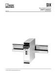
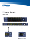
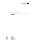
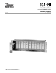
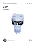
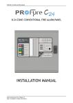
Isolated & Non-Isolated
PC-Programmable Temperature Transmitters
TRY& TRX
Isolated (TRY) & Non-Isolated (TRX)
PC-Programmable Temperature Transmitters
June 2014
235-701-00F
TRY& TRX
All product names are registered trademarks of their respective companies.
Quick-Start
Most users familiar with a PC and Windows will not have a need for the information in this
manual. Moore Industries suggests that if you do need to refer to the information here,
rely heavily on the Table of Contents that follow this Quick-Start Guide.
The majority of configuration work with these transmitters can be carried out from the
Main Configuration Screen of the PC Configuration Program (see Figure 3, page 8). The
menus and screen prompts are in “plain english”, and the help system should guide most
users through most of the configuration procedures without any problems.
In general, the use of the TRY or TRX transmitter follows this path:
1.
Installing the Configuration Software (page 10)
2.
Connecting the TRY/TRX to the PC (page 10)
3.
Input Connection Hookups (page 11)
4.
Scale the Input (page 15)
5.
Scale the Output (page 16)
6.
Trim the Input (page 17)
7.
Trim the Output (page 17)
8.
Download the Configuration File (press PROG button)
9.
Save the Configuration File to disk for future reference or
use with another unit (page 22)
10. Install the unit (page 23)
Table of Contents
Introduction.............................................................................................................................................. 5
The TRY & TRX........................................................................................................................................ 5
Specifications......................................................................................................................................... 6
Input Type & Accuracy....................................................................................................... 7
Ordering Information......................................................................................................... 8
Everything You Need is Included....................................................................................... 8
Configuring a TRY & TRX................................................................................................................ 9
What is First...................................................................................................................... 9
What is Next...................................................................................................................... 9
Installing the Software..................................................................................................... 10
Gathering the Equipment Needed.................................................................................. 10
PC Configuration Software Summary............................................................................. 12
Keeping What You’ve Got Safe—Using the “Get Setup” Function................................... 13
Selecting Input Type, Wiring, etc..................................................................................... 14
Scaling the Input (also: Setting Reverse Output)........................................................... 15
Setting the Reverse Output............................................................................................. 15
Scaling the Output........................................................................................................... 16
Applying Configuration Settings to Your Transmitter........................................................ 16
Trimming the Input.......................................................................................................... 17
Trimming the Output........................................................................................................ 17
Setting Miscellaneous Functions--Engineering Unit Readout, Input Filtering,
Upscale or Downscale Drive, and Broken Wire Detection.............................................. 18
Setting Output Damping.................................................................................................. 19
Using the Loop Test......................................................................................................... 19
Creating a Custom Linearization Table........................................................................... 20
Managing Configuration Files............................................................................................22
Saving the Configuration Files to Disk............................................................................ 22
Retrieving a Configuration File from Disk........................................................................ 22
Retrieving a Configuration File from a Connected TRY or TRX...................................... 22
Installing and Connecting the TRY or TRX.......................................................................23
Physical Dimensions....................................................................................................... 24
Connecting the TRY or TRX in an Application................................................................ 25
Operating the TRY or TRX.............................................................................................................25
Maintaining the TRY or TRX........................................................................................................25
Troubleshooting the TRY or TRX.............................................................................................26
Configuration Software Error Messages......................................................................... 26
Contacting Customer Support......................................................................................... 26
Appendix A--Intrinsically Safe Diagrams..........................................................................27
TRY & TRX
Introduction
The TRY & TRX
The TRY and TRX are 2-wire (loop-powered)
temperature transmitters. They are configured using
a personal computer (PC) and the software program
provided by Moore Industries.
Both the TRY and the TRX transmit input from a
thermocouple, or an RTD, a direct resistance or
millivolt source, or a potentiometer as a linearized,
scaled and offset 4-20 milliamps (mA). Their output
signal is proportional (or, by user designation inversely
proportional) to the input. Refer to Figure 1.
About this Manual
Wherever you see a “Note”, “Caution”, or “WARNING
” pay particular attention.
• A “Note” provides information to help you avoid minor inconveniences during calibration, installation,
or operation of the TRY and TRX.
The TRY provides 1500Vrms isolation between
input and output (500Vrms isolation for the DIN-style
version). The TRX is a non-isolating transmitter.
• A “Caution” provides information on steps to take
in avoiding procedures and practices that could risk
damage to the TRY and TRX or other equipment.
• A “WARNING ” provides information on steps to
take in avoiding procedures and practices that
could pose safety risks to personnel.
Figure 1. Use the PC-Programmable TRY or TRX as an interface between temperature sensors and control systems such as a DCS, PLC or
PC-based control system.
Isolated,
Scaleable
4-20mA
2-Wire
(Loop-Powered)
RTD
Thermocouple
Millivolts
Resistance
Potentiometer
Complete,
Ready-to-Install
Temperature
Assemblies
Available
Demand MOORE Reliability 5
TRY & TRX
Specifications
Performance
Input Accuracy:
Refer to Table 1
Output Accuracy:
4.8µA (±0.03% of 4-20mA
span)
Overall Accuracy: The
overall accuracy of the
unit is the combined input
and output accuracy. It
includes the combined
effects of linearity,
hysteresis, repeatability
and adjustment resolution.
It does not include ambient
temperature effect. For
T/C input only, add the
Reference Junction
Compensation error
Reference Junction
Compensation Accuracy:
±0.45°C
Stability: Error is in
Maximum Conformance
Range
Performance
(Continued)
Stability Input to Output
1yr 3yrs 5yrs
T/C, mV 0.11 0.18 0.24
RTD
Ohm
Pot.
0.13 0.22 0.28
Isolation: For TRY in HPP
housing, 1500Vrms input
to output; For TRY in DIN
housing, 500Vrms input to
output to case
Measurement Cycle:
Output updates 8 times per
second
Response Time: 256msec
typical for the output to
change from 10% to 90%
for an input step change of
0% to 100%
Specifications and Information subject to change without notice
6
Demand MOORE Reliability
Step Response Time:
500msec typical from the
time an input is applied
until the output reaches
90% of its final value.
Ripple: 10mV
peak-to-peak, max.
Power Supply and Load
Effect: Negligible within
power and load limits
Over-Voltage Protection:
4V, max, on input;
48V, max, on output;
48V reverse polarity
Load Capability:
500 ohms @ 24V, typical;
(Supply Voltage – 10V) /
0.024A for TRY;
(Supply Voltage – 8V) /
0.024A for TRX;
Burnout Protection:
Total Sensor Diagnostics
user-selected via Windows
configuration software;
Upscale to 24mA or
downscale to 3.3mA
Output Current Limiting:
21.4mA for input overrange;
23.6mA for sensor failure
or broken wire
T/C Input Impedance:
40M ohms, nominal
RTD Excitation:
250µA, ±10%
RTD Lead Wire
Resistance Maximum:
RTD resistance + 2 times
the lead wire resistance
must be less than 4000
ohms; Recommend <35
ohms per wire for 3-wire
RTD inputs; <5 ohms per
wire for 10 ohms Cu inputs
Ambient Operating & Storage
Conditions Range: –40°C to +85°C
(–40°F to +185°F)
Relative Humidity:
0-95%, non-condensing
Effect of Ambient
Temperature on Accuracy:
±0.015% of span/°C
change, max. (+0.001%
of ohms reading for RTD
inputs)
Effect of Ambient
Temperature on Reference
Junction Compensation:
±0.015°C/°C change
RFI/EMI Immunity:
20V/m @ 20-1000MHz,
when tested according to
SAMA standard 33.1.
(10V/m @ 80-1000MHz, 1K
AM, when tested according
to IEC 1000-4-3-1995)
Common Mode Rejection:
100dB, min., @ 50/60Hz
Normal Mode Rejection:
100dB, typical, @ 1V peakto-peak, 50/60Hz
Adjusments All settings made
using Windows-based
configuration program,
then stored in non-volatile
memory
Weight HPP-style housing:
65g (2.3 oz)
DIN-style housing:
184g (6.5 oz)
LH housing styles: 549 g
(19.4 oz)
TRY & TRX
Table 1.
Input Types, Ranges, Minimum Span and Maximum Range Specifications, and Accuracy of the TRY and TRX
Input
Type
RTD
Platinum
Nickel
Copper
Ohms
T/C
Millivolts
Direct resistance
α ∗
Ohms
Conformance
Range
Minimum
Span
Input Accuracy
Maximum
Range
0.003750
1000
-50 to 500°C
-58 to 932°F
±0.11°C±0.2°F
-100 to 560°C
-148 to 1040°F
0.003850
100, 200, 300,
400, 500, 1000
-200 to 850°C
-328 to 1562°F
±0.21°C±0.38°F
-240 to 960°C
-400 to 1760°F
0.003902
100, 200, 400
500, 1000
-100 to 650°C
-148 to 1202°F
±0.15°C±0.27°F
-150 to 720°C
-238 to 1328°F
0.003911
100, 500
-200 to 630°C
-328 to 1166°F
15°C (27°F) for
100 ohm inputs
±0.17°C±0.31°F
-235 to 710°C
-391 to 1310°F
0.003916
100
-200 to 510°C
-328 to 950°F
10°C (18°F) for
200 ohm inputs
±0.14°C±0.25°F
-240 to 580°C
-400 to 1076°F
0.003923
98.129
-200 to 600°C
-328 to 1112°F
±0.16°C±0.29°F
-235 to 680°C
-391 to 1256°F
0.003926
100, 470,
500
-200 to 630°C
-328 to 1166°F
±0.17°C±0.31°F
-235 to 710°C
-391 to 1310°F
0.003928
100
-200 to 850°C
-328 to 1562°F
±0.21°C±0.38°F
-260 to 962°C
-436 to 1763.6°F
0.000672
120
-80 to 320°C
-112 to 608°F
±0.16°C±0.29°F
10°C (18°F)
-100 to 360°C
-148 to 680°F
-50 to 250°C
-58 to 482°F
±1.2°C±2.16°F
100°C (180°F)
-65 to 280°C
-85 to 536°F
0.000427
9.035
7.5°C (13.5°F)
for 500 and
1000 ohm inputs
−
n/a
or Potentiometer
n/a
n/a
0-4000 ohms
30 ohms
±0.4 ohms
J
n/a
n/a
-180 to 770°C
-292 to 1418°F
35°C
63°F
±0.28°C±0.5°F
-210 to 770°C
-346 to 1418°F
K
n/a
n/a
-150 to 1372°C
-238 to 2501.6°F
40°C
72°F
±0.3°C±0.54°F
-270 to 1390°C
-454 to 2534°F
E
n/a
n/a
-170 to 1000°C
-274 to 1832°F
35°C
63°F
±0.26°C±0.47°F
-270 to 1013°C
-454 to 1855.4°F
T
n/a
n/a
-200 to 400°C
-328 to 752°F
20°C
36°F
±0.24°C±0.43°F
-270 to 407°C
-454 to 764.6°F
R
n/a
n/a
0 to 1768°C
32 to 3214.4°F
50°C
90°F
±0.71°C±1.28°F
-50 to 1786°C
-58 to 3246.8°F
S
n/a
n/a
0 to 1768°C
32 to 3214.4°F
50°C
90°F
±0.71°C±1.28°F
-50 to 1786°C
-58 to 3246.8°F
B
n/a
n/a
400 to 1820°C
752 to 3308°F
75°C
135°F
±0.43°C±0.77°F
200 to 1836°C
392 to 3336.8°F
N
n/a
n/a
-130 to 1300°C
-202 to 2372°F
45°C
81°F
±1.33°C±2.39°F
-270 to 1316°C
-454 to 2400.8°F
C
n/a
n/a
0 to 2315°C
32 to 4199°F
100°C
180°F
±1.16°C±2.09°F
0 to 2338°C
32 to 4240.4°F
DC
n/a
n/a
-50 to 1000mV
4mV
±0.04mV
-50 to 1000mV
* α values with both 32 and 128-point linearization curves are available. (lower resolution values provided for compatibility with older units.)
Demand MOORE Reliability 7
TRY & TRX
Ordering Information
Unit
Input
Output
TRY
Isolated,
PC-
Programmable
Temperature
Transmitter
PRG
Programmable with
supplied
Configuration Software
(see Table
1 for descriptions
of available
input types;
Factory Configuration
available)
4-20MA
User
scaleable
with
supplied
software
TRX
Non-
Isolated,
PC-
Programmable
Temperature
Transmitter
Power
TRY
10-42DC
10-30DC
Required
for -ISA,
-ISC,
-ISE and
-ISF options
TRX
8-42DC
8-30DC
Required
for -ISA,
-ISC,
-ISE,
and -ISF
options
Options
-ISA TestSafe
approved IS
(ANZEx)
-ISC CSA
approved IS
and NI (HPP)
-ISE ATEX
approved IS
(HPP)
-ISF FM
approved IS
and NI (HPP)
-FMEDA Unit
comes with
Failure Modes,
Effects and
Diagnostic
Analysis
(FMEDA) data
for evaluating
the instrument
for suitability
of use in a
safety-related
application
Housing
DIN DIN-style aluminum housing mounts on 32mm
G-type (EN50035) and 35mm Top Hat (EN50022) rails
HPP Hockey-puck housing for mounting in standard connection heads
LH1NS‡ Connection head with two entry ports: ½-inch NPT cable
and process–black PBT polyester cover
LH1MS‡ Connection head with two entry ports: M20 cable and
½-inch NPT process–black PBT polyester cover
LH1CS‡ Connection head with two entry ports: M20 cable and G½
(BSP) process–black PBT polyester cover
LH1NX Connection head with ½-inch NPT entry and mounting plate
for customer’s air duct opening–black PBT polyester cover
LH2NS(*) or (‡) Explosion-proof connection head with two entry
ports: ½-inch NPT cable and process–black metal cover
LH2MS(*) or (‡) Explosion-proof connection head with two entry
ports: M20 cable and ½-inch NPT process–black metal cover
*
‡
Either A or E suffix
A suffix indicates ANZEx/TestSafe (Ex d) Flame-Proof approvals (i.e. LH2NSA)
E suffix indicates ATEX (Ex d and tD) Flame-Proof approvals (i.e. LH2NSE)
P suffix indicates enclosure comes equipped with base plate and U-bolts for mounting on a 2-inch pipe (i.e. LH1NSP)
When Ordering, specify: Unit/Input/Output/Power/Option(s) [Housing]
Model number example: TRY/PRG/4-20MA/10-30DC/-ISF [LH2MSP]
Model and Serial Numbers Moore Industries uses a
system of model and serial numbers to keep track of
all of the information on every unit it sells and services.
If a problem occurs with a TRY or TRX, check for a tag
affixed to the unit listing these numbers. Supply the
Customer Support representative with this information
when calling.
If additional units are needed, use the information
printed in bold text in the table above to “build” a
model number for the type of transmitter required.
8
Demand MOORE Reliability
Each TRY or TRX order comes with one copy of our
Configuration Software (Windows 2000, XP, Vista, and
7 compatible).
To order additional or replacement cables, specify
Moore Industries’ part number 803-040-26, or
803-039-26 for the special cable equipped with its
own, self-powered input-to-output isolation circuit for
operation in areas of high ground potentials.
TRY & TRX
Configuring a TRY/TRX
One of the benefits of the TRY and TRX transmitters is
their easy-to-use PC Configuration Program; there are
no internal or external controls to adjust or jumpers
to change. All operating parameters are set using
the PC program included with each shipment. These
settings are downloaded in the form of a Configuration
File into nonvolatile unit memory (EEPROM) over a
connection between the PC’s serial (COM) port and a
COM port on the transmitter.
This section of the manual contains instructions for
configuring the TRY or TRX:
• Installing the Software (page 6)
• Saving the Default Configuration (page 9)
(Keeping What You’ve Got Safe)
• Selecting Input Type, Wiring Configuration,
etc. (page 10)
• Scaling the Input/Setting Reverse Output
(page 11)
• Scaling the Output (page 12)
• Trimming the Input (page 13)
• Trimming the Output (page 13)
• Setting Miscellaneous Parameters,
including Readout Engineering Units in °F
or °C, Input Filtering, Upscale or Downscale
Drive on Sensor Failure, and Broken Input
Wire Detection (page 14)
• Setting Output Damping, Using the Loop Test
(page 15)
What is First
First, it is necessary to install the Configuration
Program on a PC. Once the program is loaded and
running, nearly all of the operating parameters for the
connected transmitter are shown on a single screen
(see Figure 3). This makes it easy to determine which
aspects of transmitter operation need to be changed
to suit the application requirements.
What is Next
Once the Configuration Program is installed on the
PC, the TRY or TRX can be connected to equipment
to simulate input and monitor output, and with the PC
program, the user can view and/or change its
operating parameters.
No Transmitter Needed
It is not necessary to connect the TRY or TRX to a PC
to create configuration files. The Configuration
Program can be run without connecting a transmitter,
and most operating parameters can be set without
benefit of input from a sensor or from a transmitter.
This makes it easy to create a set of operating
parameters, save them to disk, and download them to
one or more transmitters at a later time.
Note, however, that not all parameters can be set
without a transmitter. In some cases, a source of input
is also required.
The transmitter must be connected to the PC in
order to:
• Trim Input
• Creating Custom Linearization Tables
(page 16)
• Trim Output
• Assign a Tag
• Managing Configuration Files (page 18)
• Perform a Loop Test
• Receive (via download) a Configuration File
And, perhaps most importantly...
• SAVE THE CONFIGURATION FILE ALREADY IN
THE TRANSMITTER’S MEMORY (refer to
“Keeping What You’ve Got Safe—Using ‘Get
Setup’”, on page 9)
Demand MOORE Reliability 9
TRY & TRX
Installing the Configuration
Software
Refer to Table below for the equipment needed.
1.
Insert the Moore Industries Interface Solution PC Configuration Software CD into
the CD drive of the PC. Access the CD and
open the “SDY SIY TDY TRX TRY PC Configuration Software” folder.
2. Double-click the installation program located in the folder. Follow the prompts to correctly install the program.
Once the Configuration Program is installed on the
PC, the SIY can be connected to equipment to
simulate input and monitor output. This makes it easy
to create a set of operating parameters, save them to
disk, and download them to one or more instruments
at a later time.
Gathering the Equipment Needed
It is possible to create a Configuration File for a
transmitter without ever connecting the transmitter to
a PC. Most TRY or TRX operating parameters can
be set up, saved in a Configuration File, and stored
on disk entirely within the Configuration Program—
without ever communicating with a transmitter.
It is not possible to trim the transmitter input or
output without a transmitter, a source of input,
and a meter (for output trimming). Likewise, it is
not possible to use the Loop Test function of the
transmitter unless everything is setup as shown in
Figure 2, and it is not possible to store a tag name in
the memory of a transmitter without connecting that
transmitter to the Configuration Program.
Table 2 lists the things needed to setup the TRY or
TRX as shown in Figure 2.
Note:
Be sure to use calibrated test equipment when
performing any trimming operations on the TRY or
TRX. Moore Industries uses equipment rated 5:1
over the rated accuracy of the unit under test.
We recommend the use of equipment
rated at least 3:1.
Connecting the TRY or TRX to the
PC
Connect the RS-232 end of the cable to the
PC’s COM port.
See Table below for information on the
necessary equipment.
Table 1. Assembling the equipment needed to configure the SIY
Device Current or Voltage Source
Power Supply
Multimeter (optional)
Precision Load Resistor (optional)
Personal Computer
Moore Industries PC
Configuration Software
Communication Cable
10
Demand MOORE Reliability
Specifications
Accurate to 0.05% of span for the intended application
10-42Vdc, ±10%
Accurate to ±0.025%; e.g., Fluke Model 87
Accurate to ±0.025%; e.g., HP Model 3478A
Microsoft Windows based PC;
16Mb free RAM; 20MB free disk space on hard drive
Microsoft Windows XP, Vista or 7 and 1 (one) serial port
or one available USB port
Version 1.0 or greater, successfully installed to the hard drive
Non-Isolating 803-040-26, Isolating 803-039-26, USB Cable (PN 208-236-00), or
Fuse Protected USB Cable (PN 804-030-26)
TRY & TRX
Figure 2. Use the PC Configuration Software to program the TRY or TRX.
POWER
SOURCE
10-42Vdc
+
CURRENT
METER
0-50mA
–
–
+
TRY/TRX COMMUNICATION CABLE
803-040-26 FOR NON-ISOLATED
803-039-26 FOR ISOLATED
208-236-00 USB Cable
804-030-26 Fuse Protected USB Cable
COM
+PS
–PS
or
1
TO SERIAL
(COM) PORT
OF PC
2
TX/RX
FUSE
4
3
COMM
+
TO
COM PORT
OF PC
–
CALIBRATED
INPUT
SIMULATOR
2-WIRE RTD, TC, OHM
or
MILLIVOLTS
Input Connection Hookups
1
1
1
2
2
4
3
2
4
3-WIRE RTD
OR
RESISTANCE INPUT
2-WIRE RTD
OR
RESISTANCE INPUT
2
4
2
4
3
3
POTENTIOMETER
INPUT
4-WIRE RTD
OR
RESISTANCE INPUT
1
1
1
2
4
3
3
+
4
3
–
THERMOCOUPLE
INPUT
+
–
MILLIVOLT
INPUT
Demand MOORE Reliability 11
TRY & TRX
PC Configuration Software Summary
Figure 3. Main Configuration Screen Summary
7
6
1
8
2
5
3
4
1. TRY/TRX Status The left column of the screen
displays the input, output, and settings of the TRY or
TRX. This column will change to reflect the values on
the rest of the screen when you program the TRY or
TRX with its new values.
2. Calibration Use these radio buttons to change
from “Measurement Mode”, the mode that you will
be working in from your PC, and “Calibration Mode”,
the mode that you will select when using a handheld
calibrator to simulate input to the unit.
3. “Help” Buttons The “Help” and “About” buttons
both provide information on the TRY or TRX
Configuration Software. The “CustTable” button allows
you to set up a custom linearization table for your unit.
4. File Management Buttons This set of nine buttons
are essential to all the functions of the Configuration
Software, and will be used often.
The names and functions of the individual command
buttons may change when you press a button.
12
Demand MOORE Reliability
5. Output These scroll bars control the scaling and
damping values of the TRY or TRX. When certain
options are selected, these scroll bars are renamed to
adjust the reverse output and the loop test.
6. Input Range and Setup Options Use this section
to configure the transmitter’s range of input and
parameters of its display options.
7. Input Type The top pull-down menu of this
section selects the type of input that the TRY or TRX
will accept: Millivolt, Ohms, RTD, Thermocouple, or
Potentiometer. The pull-down menus below it change
to provide only the options for the input type you have
selected.
8. Communication The communication menu
displays the status of the TRY or TRX: if it is
connected, and to which COM port it’s connected to.
The yellow light in the upper right corner of this section
will flash if the transmitter is connected.
TRY & TRX
Keeping What You’ve Got Safe—
Using “Get Setup”
Every TRY or TRX is shipped from the factory with a
Configuration File already installed in its memory. This
file is comprised of either the factory default set of operating parameters, or of the set of parameters specified by the customer at the time of order.
CAUTION:
Any time a connected TRY or TRX is “programmed”
by downloading a Configuration File into memory,
ALL of the configuration parameters
resident in the transmitter memory
at the time of the download are OVERWRITTEN
with whatever parameters are showing
on the Configuration Program Screen. All previous
parameters are then unrecoverable.
Click on the “Get Setup” button at the bottomcenter of the Configuration Program Main
Screen (see Figure 3).
The screen will flicker once, and the settings
shown on the left area of the screen will match
those showing on the right.
3.
Click on the “File” button. This brings up an
Explorer-like set of windows on the left area of
the screen.
4.
Enter a name for the current Configuration File
(the one already in the transmitter’s memory),
and click on the “Save” button.
Note:
File names must follow the DOS convention; Eightcharacter maximum and no suffix.
The Configuration Program adds
a suffix to the file name automatically.
This includes things like, input type, tag name,
calibration date, input and/or output trim values, etc.
IMPORTANT:
To safeguard against the accidental loss of a
Configuration File, always use the “Get Setup” button
and the File Management facilities under the “File”
button, located at the bottom-center of the
Main Configuration Screen.
To save the Configuration File already resident in the
transmitter’s memory:
1.
2.
5.
Answer “Yes” to save the named file to disk.
The left side of the screen will now show the
name of the file entered in Step 4. The
“starting point” of the TRY or TRX Configuration Process is now saved on the PC disk. If
you decide to edit the configuration, this file can
always be downloaded back to the transmitter.
6.
Click on “QuitFile” to return to the Main
Configuration Screen.
Start the PC Configuration Program, making
sure that the transmitter is connected as shown
in Figure 2.
Demand MOORE Reliability 13
TRY & TRX
Selecting Input Type, Wiring, etc.
Use the selection tools in the Input Type box to choose
the sensor type that the TRY or TRX will be reading.
Moore Industries suggests saving the initial settings
resident in the transmitter before making any changes
(refer to “Keeping What You’ve Got Safe”, page 9).
After saving, select the appropriate Input Type values as shown in Figure 4. Continue to change the remaining areas in Input Type (such as ohms, linearization, custom table, or # wires,
depending on your sensor type).
Figure 4. Choosing the Input Type for the TRY or TR
Note:
The Custom Input Linearization Table facility is available only with the “Millivolts” input selection.
RTD input selections distinguished by the “E” suffixed
alpha value selections use 128-bit linearization curves.
RTD selections without the “E” suffix use standard, 32bit curves. For RTD and TC applications all curves are
stored in the installation directory as files.
IMPORTANT:
Settings on the Main Configuration Screen
do not take effect in the unit until the Configuration
File is downloaded.
Note:
Once you have completed all parameters you wish
to configure, please refer to “’Applying Configuration
Settings to your Transmitter” (page 12).
.
14
Demand MOORE Reliability
TRY & TRX
Scaling the Input
IMPORTANT:
Settings on the Main Configuration Screen
do not take effect in the unit until the Configuration
File is downloaded.
This parameter allows the user to set the TRY or TRX
to scale its output in response to a portion of the total
range of the selected input type. In a reverse output
application, the TRY or TRX output drops in proportion
to a rise on the input, and rises in proportion to a drop
on the input.
Note:
Once you have completed all parameters you wish
to configure, please refer to “’Applying Configuration
Settings to your Transmitter” (page 12).
The instructions assume that the Configuration
Program has been loaded successfully (page 6).
To set the scaling for the Input to the TRY or TRX:
1.
Start the PC Configuration program and connect a transmitter. Press the “Get Setup” button
to display the transmitter’s current configuration.
Setting Reverse Output
Note:
It is not necessary to connect a unit to the PC in
order to scale the input.
2.
With the Configuration Program Main Screen
showing (Figure 3, page 8), select the “Input Zero” box in the upper right corner of the
screen.
Figure 5. The Input Zero/Full menu
3.
Enter the desired 0% input value into the “Input
Zero” value box.
4.
Repeat the above step to set the desired 100%
input value in the “Input Full” box.
Any value which falls within the range of the
selected measurement type may be used for
“Input Zero” and “Input Full” percentages
a.
Select the “Input Zero” box (Figure 5).
b.
Enter a value GREATER THAN THE
INTENDED FULL SCALE INPUT.
c.
Select the “Input Full” box.
d.
Enter a value LESS THAN THE ZERO SCALE
INPUT entered in Step b.
The Configuration Program will display a message in the output section of the screen to
indicate that a Reverse Output situation exists
(see Figure 6).
Demand MOORE Reliability 15
TRY & TRX
Note:
The minimum difference between
0% output and 100% output is 4.000mA.
Figure 6. Scale the output or set the Reversed Output using the
bars in the bottom right of the Main Configuration Screen.
IMPORTANT:
Settings on the Configuration Program Screen do
not take effect in the unit until the Configuration File
is downloaded.
Applying Configuration Settings to
Your Transmitter
1.
Scaling the Output
a. Create a Configuration File by setting
different parameters.
The TRY or TRX can be configured to scale its
4-20mA output to offset the performance or calibration
of other instruments in the process loop.
The instructions assume that the Configuration
Program has been loaded successfully (page 6).
Moore Industries also suggests saving the initial
settings resident in the transmitter before making any
changes (refer to “Keeping What You’ve Got Safe”,
page 9).
b. Save the current settings into a file on
disk as a back-up or to down load later.
Refer to “Keeping What You’ve Got Safe”,
starting with Step 3 on page 9.
c. Download the current settings into
memory
2.
To enable the Download Process, click on
the “Stop” button at the bottom-center of
the screen, then on the “Prog” button. This
transfers the settings from the screen to the
memory of the connected transmitter.
The Status Bar in the upper-left corner of the
Configuration Program screen will display the
progress of the download of the Configuration
File to the connected transmitter.
When the download is complete, the
Configuration Program will emit a faint, yet
distinctly audible “beep” to indicate that the
download was successful and will show the
configuration setting resident in memory
towards the left side of the screen.
3.
Click on the “Start” button to re-enable the
Configuration Program’s monitoring of the
connected transmitter.
The status area of the Configuration Program
screen will display the “Measurement ON”
message.
To set the output of the TRY or TRX:
1.
Start the PC Configuration program and
connect a TRY or TRX as shown in Figure
2. Press the “Get Setup” button to display the
transmitter’s current configuration.
Note:
It is not necessary to connect a unit to the PC in
order to scale the output.
2.
3.
16
Enter the desired 0% output value (between
3.800mA and 17.400mA) in the “Output Zero”
box at the lower right corner of the screen
(see Figure 6), or click and drag the slide bar,
adjacent to the box, to adjust the value for 0%
as desired.
Enter the desired 100% output value (between
7.800mA and 21.400mA) in the “Output Full”
box, or click and drag the slide bar to adjust the
value.
Demand MOORE Reliability
Select one of these options:
TRY & TRX
CAUTION:
Any time a connected TRY or TRX is “programmed”
by downloading a Configuration File into memory,
ALL of the configuration parameters resident in the
transmitter memory at the time of the download are
OVERWRITTEN.
This includes things like, tag name, calibration date,
trim values, etc.
7.
Attach the sensor that you wish to trim to the
transmitter and place the sensor in a calibration
bath. Adjust the bath until its temperature
settles. Click “Trim Upper” and wait for it to
capture the value (about 10 seconds).
Caution:
If planning on beginning a new task, ensure that you
have saved your lower trim value of your Input Trim
before proceeding to Steps 8 and 9.
Trimming the Input
Use this feature to enhance the accuracy of the transmitter by precisely matching its actual reading of the
input to its scaling of the either one or two input points.
Trim the input by following the directions below:
8.
Click on the button labeled “QuitTrim”, then the
“Stop” button, and finally the “Prog” button to
send the trim values to the transmitter.
9.
Click on the “Start” button to re-enable the
Configuration Program’s monitoring of the
connected transmitter.
Note:
Figure 9. Trim Capture Box
The “Input Trim” procedure may require several
hours for completion. Please determine whether
or not your process requires this function before
proceeding.
1.
Connect the transmitter to your PC using the
setup shown in Figure 2. Press the “Get Setup”
button to display the transmitter’s current
configuration.
2.
Click “Start”, then “InpTrim”.
3.
Click the radio button labeled “Input Trim On”.
4.
Select whether you will trim two points (upper
and lower) or just one point by clicking on the
appropriate radio button in the “Trim Pnts”
section.
5.
In the “Trim Lower” and “Trim Upper” boxes,
type in the sensor’s value that you are trimming.
6.
Attach the sensor that you wish to trim to the
transmitter and place the sensor in a calibration
bath. Adjust the bath until its temperature
settles. Click “Trim Lower” and wait for it to
capture the value (about 10 seconds).
Trimming the Output
Trimming is the function that allows precise control
over the transmitter’s output. Note that to activate this
function, a unit must be connected as shown in Figure
2.
To trim TRY or TRX output:
1. Set all unit parameters on the TRY or TRX Configuration Screen as required for your intended
application.
When the Configuration File shown on the screen
has been modified for your application, click “Stop”
to stop measurement.
2. Click “OutTrim”. Monitor the output with a calibrated current meter or with a voltmeter measuring
the drop across a precision 250 Ohm resistor (see
Figure 2).
Demand MOORE Reliability 17
TRY & TRX
3. While monitoring your meter, select and move the
“Zero Scale Output” or the “Full Scale Output” slide
bar to adjust the TRY or TRX output .
4. When both zero and full scale have been adjusted
to satisfaction, press “QuitTrim”, then “Prog” to
program the transmitter with the new trim values.
The “TRY or TRX Status” area of the Configuration
Screen will reflect the new output settings.
Setting Miscellaneous Functions—
Engineering Unit Readout, Input
Filtering, Upscale or Downscale
Drive, and Broken Wire Detection
There are several “radio buttons” on the PC
Configuration Program Main Screen that control
ancillary transmitter functions. It is not necessary to
have a transmitter hooked up to the PC in order to set
these parameters and save them in a
Configuration File.
Setting Engineering Unit Readout
When a temperature sensor is designated as the input
to the transmitter, the radio buttons for “Degree” are
enabled.
Use this setting to have the Configuration Program
display the Centigrade or Fahrenheit temperature for
readout in the “Status” area of the screen whenever
the PC is being used to monitor the input from the
connected sensor.
Setting Input Filtering
Use this radio button setting to filter out noise on the
power to the transmitter.
Choosing Between
Upscale and Downscale Drive
The TRY and TRX transmitters can be configured to
provide a special warning, using its output, of a breakdown in its connected sensor or sensor wiring. Use
this radio button setting to configure the
transmitter to drive its output either up to 24mA or
down to 3.3mA when a sensor or sensor wiring
failure is detected.
18
Demand MOORE Reliability
Note:
There is a difference between the available
Full Scale output setting and the Upscale Drive,
and between the available zero scale output setting
and the Downscale Drive:
The TRY or TRX will only output 24mA or 3.3mA
(as configured) in the event of a sensor or sensor
wiring failure (upscale/downscale drive).If sensor
input drops below the rated range, output drops to a
minimum of 3.8mA. If sensor input rises above the
rated range, output rises to 21.4mA.
This allows the user to distinguish between an input
failure and an input over or under-range condition.
Disabling Broken Wire Detection
One of the premier features of many of Moore
Industries’ temperature transmitters is our Total
Sensor Diagnostics® system. During operation, the
TRY or TRX sends random micro-amp pulses through
input wiring to check for broken wiring or a burned out
sensor.
Working with a Millivolt Input
When the transmitter is connected to a PC, the
“TRY/TRX Status” section of the Main Configuration
screen displays the message “Broken Wire” whenever
problems are detected on the input, and the transmitter itself drives its output upscale or downscale.
This can cause problems for some types of millivolt input sources. To temporarily disable this feature when
the TRY or TRX is working in a millivolt input configuration, select the “Broken Wire Off” radio
button.
Working with a Thermocouple or RTD Input
Total Sensor Diagnostics can also cause problems
with some types of temperature calibrators.
When working with thermocouple or RTD
inputs, set the “Calibration” radio button in the lowerleft area of the Configuration Screen to “Calibration
Mode”. This temporarily disables Total Sensor
Diagnostics.
TRY & TRX
Setting Output Damping
Using the Loop Test
The Output Damping function allows the user to
introduce a delay into the response of the transmitter
in order to minimize the effect of step output changes.
The higher the damping value (set in seconds), the
longer the TRY or TRX will take to respond to trends
on the input.
The Loop Test feature allows the user to employ the
transmitter’s output to “trim” other instruments in the
loop.
To use the Loop Test feature, the connected TRY or
TRX must stop measuring input.
Note:
It is not necessary to connect an input device to the
PC in order to select and configure the Damping
Value.
1.
Click on the “Stop” button.
2.
Click on the “Loop Test” button.
This enables a slide bar in the lower-right area
of the Configuration Screen.
To set the damping value, either adjust the position of
the slider bar in the lower-right area of the
Configuration Program Main Screen, or enter a value
directly into the space provided.
3.
Use the slide bar to adjust the output of the
connected TRY or TRX to a percentage of the
configured scale. Monitor the effect of this on
other instruments in the loop, and adjust accordingly.
4.
Click on “Quit Loop” to stop using the Loop Test
feature.
The default damping value is 0 seconds in which
damping is off. The maximum allowable damping value
is 5.056 seconds.
Figure 10. The Output Loop Test scroll ba
s.
Demand MOORE Reliability 19
TRY & TRX
Creating a Custom
Linearization Table
Figure 12. Creating a Custom Linearization Table.
The TRY or TRX support user-defined linearization
of mV inputs. Up to 85 input/output points can be
defined, and the user can also specify the format and
engineering units of the output (viewable with the Configuration Program). A Custom Linearization Curve is
used for mV inputs only.
This section explains how to create a Custom Linearization Table for downloading into TRY or TRX
memory.
The instructions assume that the Configuration Program has been loaded successfully. Moore Industries
also suggests saving the initial settings resident in the
transmitter before making any changes.
To create a Custom Linearization Table:
1.
Attach the equipment listed in Table 1 as shown
in Figure 2 and start the PC Configuration Program.
Note:
Connect the unit to a PC in order to create a Custom
Linearization Table. You may work On or Off-Line.
2.
4.
Use the pull-down menu to set “Linearization ON”. Then click the “CustTabl” button in
the lower-left area of the Main Configuration
Screen.
Figure 11. Linearization Must be set to ON to Create a Custom
Table.
Use the table fields to set values for input and
output from the transmitter’s intended application.
Use the Up, Down, Left, and Right arrow keys
on the PC keyboard to move the cursor among
the cells in the table.
5.
Use the “Restore” button to reset the table to
the table stored in the TRY OR TRX’s memory.
CAUTION:
Restoring the configuration file erases any values in
the table, overwriting them with whatever is stored in
the most recent file.
3.
20
Click on the “CustTabl” (Customize
Linearization Table) button. This causes the
Configuration Program to change its upper-right
corner area to accommodate the table.
Demand MOORE Reliability
6.
Use the “EGU” field to set the Engineering units
of the readout from the transmitter when connected to the Configuration Program.
7.
Set the “Output Format” field to the desired
resolution using the pull-down menu.
8.
Enter the number of points to use to constitute
the Linearization Table in the “Points” field.
TRY & TRX
The Rules for Custom Linearization:
•
9.
The difference between any consecutive
values in the table (in either column) must be
less than 50% of the entire configured range.
10. Click on the “Prog” (Program) button to download the output trim settings into the transmitter
memory.
Note:
Values in the “Inp mV” column must be in ascending
order and must fall within a range of -50 to 1000 mV.
•
CAUTION:
Any time a connected TRY or TRX is “programmed”
by downloading a Configuration File into memory,
ALL of the configuration parameters resident in the
transmitter memory at the time of the download are
OVERWRITTEN.
One “Output EGU” value per “Input mV” value
only.
Note:
Values in the “Out EGU” column must fall within a
range of ±999999. The output must be scaled to
your “Output EGU” Table range.
•
It is not necessary to use all 85 available
points, but the first and last points in the curve
always default to the 0% and 100% input scale
(input range).
•
If you decide not to use all 85 points, you must
change the number of points in the “Points”
field to the number you wish to use.
When the table is complete, click on the “QuitTabl” button and answer “Yes” on the pop-up
dialog box. You may save the configuration to a
file whether you are On or Off-Line.
This includes things like: tag name, calibration date,
trim values, etc.
Once a transmitter’s memory is “erased”
in this fashion, the old operating parameters
are unrecoverable, and will have to be
regenerated from scratch if needed again.
Note:
Moore Industries suggests filling in the EGU
(Engineering Units), then the number of points, and
finally the values in the table.
Demand MOORE Reliability 21
TRY & TRX
Managing Configuration
Files
Note:
File names must follow the DOS convention.
Eight-character maximum and no suffix.
Once all the parameters for a transmitter are set, they
can be saved to disk on the PC using the “File” menus
and fields.
Figure 13. The File Menu.
The Configuration Program adds
a suffix to the file name automatically.
3.
Use the Explorer-like interface to designate the
location on the PC drive (or floppy) for the file to
be saved.
4.
Click on “Save”
5.
Click “Yes” to save the named file to disk.
The left side of the screen will now show the
name of the file entered in Step 2 resident on
disk.
Retrieving a Configuration
File from Disk
u.
Saving a Configuration File to Disk
1.
2.
22
Click on the “File” button. This brings up an
Explorer-like window on the left area of the
screen.
Enter the file name that you wish to save in the
“Selected File Name” box.
Demand MOORE Reliability
1.
From the Main Configuration Screen, click on
the “File” button to bring up the File Management portion of the program.
2.
Use the Explorer-like file display (see Figure
13) to locate the file to be retrieved, and click
on the file to highlight it. Once you’ve clicked
on the file it is read and the screen is updated.
3.
Click on the “Quit File” button.
You may also edit the screen configuration
and save it to another file. However, once you
click the “Quit File” button you will be asked
whether you want to keep the current file
configuration or restore the previous version
before saving.
The Configuration Screen will change to show
the parameters entered into the retrieved file.
The parameters can now be edited and/or
downloaded into the memory of a connected
TRY or TRX.
Retrieving a Configuration File
from the Connected TRY or TRX
Make sure a transmitter is connected and communicating properly with the Configuration Program, then
simply click on the “GetSetup” button.
TRY & TRX
Installing and Connecting the
TRY or TRX
The Main Configuration Screen changes to show the
parameters resident in the memory of the connected
transmitter. The parameters can now be edited, saved
to disk, and/or edited and re-downloaded into memory.
Now that the TRY or TRX has been programmed to
your satisfaction, it is ready for installation.
Note:
The TRY and TRX are available in both DIN and HPP
housing styles, and are available with a number of enclosure options. Consult your local Moore Industries’
Interface Solutions Expert for information on the type
of enclosure that best suits your application.
Connection to another device will not change the
Configuration Screen. This is beneficial when
you must configure several devices with the same
configuration. In this case you would simply
configure the unit and click the “Stop” button and
then the “Prog” button. If no sensor is connected
during configuration download, click the “Stop BW”
button and then the “Prog” button.
Figure 14. Connecting the TRX or TRY to the loop.
DC
POWER
CURRENTDRIVEN
INSTRUMENT
+
–
+
–
DC Power
8-30Vdc FOR TRX w/ INTRINSIC SAFETY OPTIONS
8-42Vdc FOR STANDARD TRX
10-30Vdc FOR TRY w/ INTRINSIC SAFETY OPTIONS
10-42Vdc FOR STANDARD TRY
TRX OR TRY
(HPP
SHOWN)
+
–
COM
+PS
–PS
1
2
4
3
Input Connection Hookups
1
1
1
2
2
4
3
2
4
3-WIRE RTD
OR
RESISTANCE INPUT
2-WIRE RTD
OR
RESISTANCE INPUT
2
4
2
4
3
3
POTENTIOMETER
INPUT
4-WIRE RTD
OR
RESISTANCE INPUT
1
1
1
2
4
3
3
+
4
3
–
THERMOCOUPLE
INPUT
+
–
MILLIVOLT
INPUT
Demand MOORE Reliability 23
TRY & TRX
Figure 15. The Dimensions of the DIN housing for the TRY or TRX unit.
138mm
(5.43 in)
WHEN INSTALLED
133mm
(5.24 in)
WHEN INSTALLED
1
2
3
43mm
(1.69 in)
4
TRY
COM
C
L
80mm
(3.15 in)
+PS –PS
110mm
(4.33 in)
25mm
(1.0 in)
113mm
(4.45 in)
Figure 16. The Dimensions of the TRY or TRX HPP housing.
TOP
SIDE
BOTTOM
52mm
(2.04 in)
25mm
(1.0 in)
+PS
30mm
(1.56 in)
–PS
CL
49mm
(1.92 in)
1
CL
2
4
3
27mm
(1.05 in)
CL
CL
4 X 40
0.125 in depth
2 PLACES
33mm
(1.3 in)
24
Demand MOORE Reliability
CL
33mm
(1.3 in)
TRY & TRX
Connecting the TRY or TRX in an
Application
• For the best shielding, the shield should be run all the
way from the signal source to the receiving device.
(see Note below)
Moore Industries suggests installing the TRY or TRX
by first mounting the unit in its intended application,
then making the electrical connections to input, output,
and power. Before any installation, make sure that
the unit has been bench checked to ensure that it is
configured and calibrated properly for its intended application.
• The maximum length of unshielded input and output
signal wiring should be 2 inches.
Note:
Some of Moore Industries’ instruments can be
classified as receivers (IPT 2, IPX 2, etc.) and some
can be classified as transmitters (TRX, TRY, etc.)
while some are both a receiver and a transmitter
(SPA 2, HIM, etc). Hence, your shield ground
connections should be appropriate for the type
of signal line being shielded. The shield should
be grounded at the receiver and not at the signal
source.
Recommended Ground Wiring
Practices
Moore Industries recommends the following
ground wiring practices:
• Any Moore Industries product in a metal case or
housing should be grounded.
CE Conformity
Installation of any Moore Industries’ products that
carry the CE marking must adhere to the guidelines
in the Recommended Ground Wiring Practices
section in order to meet the EN 61326 requirements
set forth in the applicable EMC directive.
• The protective earth conductor must be connected
to a system safety earth ground before making other
connections.
• All input signals to, and output signals from, Moore
Industries’ products should be wired using a shielded,
twisted pair wiring technique. Shields should be
connected to an earth or safety ground.
Figure 17. The Dimensions of the explosion-proof housing for the TRY or TRX unit.
Safety Lock
(LH2 only)
87mm
(3.43 in)
51mm
(2.01 in)
BOTTOM
SIDE
Metal Tag
Conduit
Entry Port
92mm
(3.62 in)
30mm
(1.18 in)
9mm
(0.35 in)
M4.0 x 0.7
(4 places)
Process Connection
1/2-in NPT (N and M models) or
G½ (BSP) (C models)
2-INCH PIPE MOUNTING HARDWARE
INSIDE Instrument
Mounting Holes
40mm (1.56 in)
Instrument
Mounting
Holes
33mm
(1.30 in)
10-32
Mounting
Holes (2)
DIA. 72mm
(DIA. 2.83 in)
FRONT
61mm
(2.40 in)
84mm
(3.31 in)
89mm
(3.5 in)
2-in Pipe Bracket
Mounting Holes (4)
61mm
(2.40 in)
CL
Ground
I.D. 62mm x 19mm Deep
(2.44 in x 0.75 in Deep)
61mm
(2.40 in)
Demand MOORE Reliability 25
TRY & TRX
Operating the TRY/TRX
Once configured, installed, and supplied with the
correct power, the TRY or TRX transmitter begins to
operate immediately. Depending upon environmental
conditions, it can be expected to continue to operate
unattended indefinitely.
Maintaining the TRY/TRX
Moore Industries suggests a quick check for terminal
tightness and general unit condition every 6-8 months,
depending upon the severity of conditions. Things
such as ambient vibration, corrosive atmospheres, extreme heat or cold, etc., can play a role in shortening
the service life of any piece of electronic equipment.
IMPORTANT:
Always adhere to any site requirements for
programmed maintenance.
Troubleshooting the TRY/
TRX
If a transmitter’s performance begins to deteriorate
and a physical check of the installation uncovers no
adverse conditions or damage, remove the offending
unit from service and reperform the Configuration
Procedures from earlier in this manual.
Configuration Software
Error Messages
Data fields on the Configuration Main Screen can
change color or appearance in some way to indicate
that an attempt is being made to create a nonstandard
or ill-advised condition in the Configuration File.
“Zero or Full Scale Outside
Conformance Range”
Setting thermocouple input parameters to zero or full
scale values that fall outside the published ISA
thermocouple tables will cause this error message to
appear on screen.
This condition is “downloadable” to a TRY or TRX. It is
intended to provide the user with the ability to monitor
general trends on the input, functioning within the rated accuracy whenever input is within the conformance
range, but inherently less accurate outside the range.
26
Demand MOORE Reliability
“Reverse Output”
Setting the parameter for “Input Zero” numerically
above the parameter for “Input Full Scale” causes this
message in the “Output” section of the Configuration
Screen. This condition is downloadable to the unit,
and causes transmitter output to rise proportionally in
response to a drop on the input, and to fall proportionally as the input rises.
“Table Data Invalid”
If there is a broken or loose communication wire, ambient electronic noise, or a problem with the memory
chip inside the transmitter, this message may appear.
To fix the condition, make sure that the desired operating parameters are displayed on the Configuration
Screen, and click on the “Prog” (Program) button. This
should override the corrupt configuration
information in unit memory and reset the parameters
correctly.
Contacting Customer Support
Moore Industries is recognized as the industry leader
in delivering top quality to its customers in products
and services. We perform a battery of stringent quality assurance checks on every unit we ship. If any
Moore Industries product fails to perform up to rated
specifications, call us for help. Our highly skilled staff
of trained technicians and engineers pride themselves
on their ability to provide timely, accurate, and practical answers to your process
instrumentation questions.
Factory phone numbers are listed on the back cover of
this manual.
If problems involve a particular TRY or TRX, there are
several pieces of information that can be gathered
from the installation before the factory is called
that will help our staff get the necessary answers in
the shortest time possible. For the fastest service,
gather:
• The complete model number(s) of the problem
unit(s)
• The complete serial number(s) of the problem
unit(s)
DRAWN
1
COM
RTD & T/C:
1
Po = 0.825 W
[T2X: RTD only]
T. Code: T6 @ 60˚C Maximum Operating Ambient.
Temperature Range: -40˚C £ T amb. £ +60˚C
US NEC 505 (T2X & TRX-R only): Class I, Zone 0, AEx ia IIC
Intrinsically Safe: Class I,II,III; Div. 1; Groups A-G.
Non-Incendive: Class I, Div. 2, Groups A-D.
Class II, Div. 2, Groups F & G and Class III, Div. 2.
1
4 Ca or Co = 2.96 µF 4
La or Lo = 2.9 mH
3 Voc or V t = 6.51 VDC 3
Isc or It = 110 mA
2
2
Hazardous (Classified) Locations - FM (US NEC 500):
+PS
-PS
-PS
+PS
C
CB
APPROVAL
-PS
COM
Input device must be 'Agency'
approved per application area
(CSA, EECS, FM, ISSeP,
LCIE, SIRA, SAA, TUV, etc...).
Entity Parameters
(Power/Loop, +PS & -PS):
Vmax or Ui = 30 VDC
Imax or Ii = 110 mA
Pmax or Pi = 0.825 W
Ci = 317 nF
Li = 0 µH
Ca or Co ³ Ci + Ccable
La or Lo ³ Li + Lcable
V max or Ui ³ V oc or V t
Imax or Ii ³ Isc or It
KEMA/CENELEC I.S. (TRX only): EEx ia IIC T4/T5
LCIE/ATEX I.S. (T2X/TRX-R):
II 2G EEx ib IIB T6
Hazardous (Classified) Locations/Areas:
CSA International
Intrinsically Safe: Class I, Div. 1, Groups A-D.
Suitable for use in: Class I, Div. 2, Groups A-D.
+PS
T2X & TRX-R [HPP]
Non-Isolated PC-Programmable
Temperature Transmitter
(Caution: The 'COM' Port Must Not Be Used In Hazardous 'Classified' Locations.)
TRX [HPP]
Non-Isolated PC-Programmable
Temperature Transmitter
(3)
G.E. 02/01
BY
(1) Apparatus which is unspecified except that it must not be supplied from, or contain under normal or abnormal conditions a source of potential with respect to earth in excess of 250 VRMS or 250 VDC
which is considered to be the Safe Area's maximum voltage.
(2) The Barrier or other Associated Apparatus must be approved by the "specific" (CSA/EECS/FM/LCIE/SAA/SIRA/TUV, etc..) certifying agency for I.S. connections in: "Class I-III, Division 1, Groups
A-G" locations. The output voltage (Voc, Vt or Vo) must not exceed 30 VDC & the output current (Isc, It or Io) must not exceed 110 mA . Also, it must be installed per the manufacturer's guidelines.
A Shunt Zener Barrier is NOT required for Non-Incendive (or Class I, Division 2 or Type N) installations.
(3) The combined Capacitance and Inductance of the inter-connecting cables and the PC Prog. Transmitters must not exceed the values indicated on the Associated Apparatus.
4- For FM applications, installation must be in accordance to 'ANSI-P12.6' (Installation of I.S. Systems for Hazardous 'Classified' Locations) and the National Electric Code 'ANSI/NFPA 70' . Also, a
dust-tight conduit seal must be used when installed in Class II and Class III environments. For CSA applications, adhere to the 'Canadian Electric Code C22.1' most current publication on I.S. installation
guidelines. For CENELEC/ATEX applications, adhere to 'EN 60079-14:1997' or any equivalent, most current and pertaining publication on I.S. installation guidelines.
5- Warning: Substitution of components may impair the Intrinsic Safety of the unit. DO NOT open the unit when either energized or if an explosive gas/dust atmoshpere is present. Disconnect power
before servicing. Also read, understand and adhere to the manufacturer's installation and operating procedures.
6- The maximum power parameters of the COM port (to be used only in safe/non-hazardous areas) are: V max = 3.0 VDC, I max = 300 µA, Pmax = 240 µW.
Ground/Earth Path
Resistance Must Not
Exceed 1
-PS
+PS
ECO 13262
DATE
REVISION
NOTICE RE PROPRIETARY INFORMATION: This drawing and the information contained herein are the proprietary property of Moore IndustriesInternational, Inc. (MII) and should not be reproduced or disclosed to any
third party without the written consent of an authorized officer of MII.
REVISED BY
100-100-38
This page contains the installation diagram for the
TRY or TRX carrying the intrinsically safe option. It
also includes guidelines for setting up zener barriers
necessary in these types of applications.
Notes:
Field Installation Diagram:
TRX, TRX-R & T2X [HPP]
DRAWING NUMBER
Appendix A: Intrinsic
Safety
(1)
TITLE
CONTROL DRAWING
CATEGORY
W. Ho
02/01
Gus H. Elias 09/00 Non-Isolated PC Prog. Temp. Xmitters.
Intrinsically Safe System
NONE
For Hazardous 'Classified' Locations.
Barrier or other
Associated
Apparatus
(2)
Non-Hazardous Safe Area
CERTIFIED PRODUCT
This is a controlled 'Related' or 'Schedule'
drawing. No modifications are permitted
without the notification and final approval of
the Q.A. Certification Engineer (related dwgs.)
or the Certifying Agency (schedule dwgs.).
Unspecified
Apparatus
Gus H. Elias 09/00
CHECKED
DECIMALS = ±inch /mm
= ±.1 /2.54
.X
= ±.03 /0.76 ENGINEER
.XX
= ±.010/0.25
.XXX
HOLES: =+.003-.002/+.08-.05 SCALE
ANGLES: = ± 30'
(UNLESS NOTED)
TOLERANCES
DO NOT SCALE DRAWING
TRY & TRX
These diagrams must be used to augment the
installation instructions earlier in this manual for units
that are to operate in areas requiring intrinsically safe
instrumentation.
Demand MOORE Reliability 27
TRY & TRX
28
Demand MOORE Reliability
EC Declaration of Conformity
Moore Industries-International, Inc.
16650 Schoenborn Street
North Hills, CA 91343-6196 U.S.A.
Date Issued: 21 Oct. 2013
No. 100-100-243 Rev. A
Page 1 of 2
Equipment Description:
Isolated PC Programmable Temperature Transmitter
Model TRY / * / * / * / * / *
* Indicates any input, output, power, options and housing as stated in the product data sheet.
Directive:
2004/108/EC (EMC: Electromagnetic Compatibility)
Specifications Conformed To:
EN 61326-1:2006 Electrical equipment for measurement, control and laboratory use - EMC requirements
Equipment Description:
Isolated PC Programmable Temperature Transmitter
Model TRY / * / 4-20mA / 10-30DC / -ISE * / HPP
* Indicates any input and options as stated in the product data sheet.
Directive:
94/9/EC (ATEX: Equipment and protective systems for potentially explosive atmospheres)
Provisions of the Directive Fulfilled by the Equipment:
Group II Category 2G EEx ib IIC T6
Notified Body for EC-Type Examination:
LCIE [Notified Body Number 0081]
33, av du Général Leclerc
92260 Fontenay-aux-Roses - France
EC-Type Examination Certificate:
LCIE 01 ATEX 6017 X
Technical Standards Referenced:
EN 50014:1997 + Amds 1 & 2 Electrical apparatus for potentially explosive atmospheres. General requirements.
EN 50020:1994 Electrical apparatus for potentially explosive atmospheres. Intrinsic safety ”i”
Equipment Description:
Isolated PC Programmable Temperature Transmitter
Model TRY / * / 4-20mA / 10-42DC / * / HPP
* Indicates any input and option as stated in the product data sheet.
Directive:
94/9/EC (ATEX: Equipment and protective systems for potentially explosive atmospheres)
Provisions of the Directive Fulfilled by the Equipment:
Group II Category 3G Ex nA IIC T6
Technical File No.: TRY-TF001
Conformity Assessment Procedure:
Internal Control of Production - Annex VIII (Module A)
EC Declaration of Conformity
Moore Industries-International, Inc.
16650 Schoenborn Street
North Hills, CA 91343-6196 U.S.A.
Date Issued: 21 Oct. 2013
No. 100-100-243 Rev. A
Page 2 of 2
Technical Standards Referenced:
EN 60079-0:2006 Explosive atmospheres Part 0: Equipment - General requirements
EN 60079-15:2005 Explosive atmospheres Part 15: Equipment protection by type of protection "n"
Equipment Description:
Isolated PC Programmable Temperature Transmitter in the LH2 Enclosure
Model TRY / * / * / * / * / LH2**E
* Indicates any input, output, power and options as stated in the product data sheet.
**Indicates any LH2 Enclosure with the ‘E’ suffix.
Directive:
94/9/EC (ATEX: Equipment and protective systems for potentially explosive atmosphere)
Provisions of the Directive Fulfilled by the Equipment:
Group II Category 2G Ex d IIC T6; Group II Category 2D Ex tD A21 IP66 T85˚C
Notified Body for EC-Type Examination:
ISSeP [Notified Body Number 0492]
Zoning A. Schweitzer 7340
Colfontaine, Belguim
EC-Type Examination Certificate:
ISSeP 08 ATEX 033 X
Technical Standards Referenced:
EN 60079-0:2006 Explosive atmospheres Part 0: Equipment - General requirements
EN 60079-1:2007 Explosive atmospheres Part 1: Equipment protection by flameproof enclosures "d"
EN 61241-0:2006 Electrical apparatus for use in the presence of combustible dust - Part 0: General requirements
EN 61241-1:2004 Electrical apparatus for use in the presence of combustible dust - Part 1: Protection by enclosures "tD"
Notified Body for Quality Assurance:
SIRA [Notified Body Number 0518]
Rake Lane, Eccleston,
Chester, Cheshire,
CH4 9JN, England
On Behalf of Moore Industries-International, Inc., I declare that, on the date the equipment accompanied by this
declaration is placed on the market, the equipment conforms with all technical and regulatory requirements of
the above listed directives.
Signature:
Deanna Esterwold, Quality Manager
EC Declaration of Conformity
Moore Industries-International, Inc.
16650 Schoenborn Street
North Hills, CA 91343-6196 U.S.A.
Date Issued: 21 Oct. 2013
No. 100-100-244 Rev. A
Page 1 of 2
Equipment Description:
PC Programmable Temperature Transmitter
Model TRX / * / * / * / * / *
* Indicates any input, output, power, options and housing as stated in the product data sheet.
Directive:
2004/108/EC (EMC: Electromagnetic Compatibility)
Specifications Conformed To:
EN 61326-1:2006 Electrical equipment for measurement, control and laboratory use - EMC requirements
Equipment Description:
PC Programmable Temperature Transmitter
Model TRX / * / 4-20mA / 8-30DC / -ISE * / HPP
* Indicates any input and options as stated in the product data sheet.
Directive:
94/9/EC (ATEX: Equipment and protective systems for potentially explosive atmospheres)
Provisions of the Directive Fulfilled by the Equipment:
Group II Category 2 G EEx ib IIB T6
Notified Body for EC-Type Examination:
LCIE [Notified Body Number 0081]
33, av du Général Leclerc
92260 Fontenay-aux-Roses - France
EC-Type Examination Certificate:
LCIE 01 ATEX 6017 X
Technical Standards Referenced:
EN 50014:1997 + Amds 1 & 2 Electrical apparatus for potentially explosive atmospheres. General requirements.
EN 50020:1994 Electrical apparatus for potentially explosive atmospheres. Intrinsic safety ”i”
Equipment Description:
PC Programmable Temperature Transmitter
Model TRX / * / 4-20mA / 8-42DC / * / HPP
* Indicates any input and option as stated in the product data sheet.
Directive:
94/9/EC (ATEX: Equipment and protective systems for potentially explosive atmospheres)
Provisions of the Directive Fulfilled by the Equipment:
Group II Category 3 G Ex nA IIB T6
Technical File No.: TRX-TF001
Conformity Assessment Procedure:
Internal Control of Production - Annex VIII (Module A)
EC Declaration of Conformity
Moore Industries-International, Inc.
16650 Schoenborn Street
North Hills, CA 91343-6196 U.S.A.
Date Issued: 21 Oct. 2013
No. 100-100-244 Rev. A
Page 2 of 2
Technical Standards Referenced:
EN 60079-0:2006 Explosive atmospheres Part 0: Equipment - General requirements
EN 60079-15:2005 Explosive atmospheres Part 15: Equipment protection by type of protection "n"
Equipment Description:
PC Programmable Temperature Transmitter in the LH2 Enclosure
Model TRX / * / * / * / * / LH2**E
* Indicates any input, output, power and options as stated in the product data sheet.
**Indicates any LH2 Enclosure with the ‘E’ suffix.
Directive:
94/9/EC (ATEX: Equipment and protective systems for potentially explosive atmosphere)
Provisions of the Directive Fulfilled by the Equipment:
Group II Category 2G Ex d IIC T6; Group II Category 2D Ex tD A21 IP66 T85˚C
Notified Body for EC-Type Examination:
ISSeP [Notified Body Number 0492]
Zoning A. Schweitzer 7340
Colfontaine, Belguim
EC-Type Examination Certificate:
ISSeP 08 ATEX 033 X
Technical Standards Referenced:
EN 60079-0:2006 Explosive atmospheres Part 0: Equipment - General requirements
EN 60079-1:2007 Explosive atmospheres Part 1: Equipment protection by flameproof enclosures "d"
EN 61241-0:2006 Electrical apparatus for use in the presence of combustible dust - Part 0: General requirements
EN 61241-1:2004 Electrical apparatus for use in the presence of combustible dust - Part 1: Protection by enclosures "tD"
Notified Body for Quality Assurance:
SIRA [Notified Body Number 0518]
Rake Lane, Eccleston,
Chester, Cheshire,
CH4 9JN, England
On Behalf of Moore Industries-International, Inc., I declare that, on the date the equipment accompanied by this
declaration is placed on the market, the equipment conforms with all technical and regulatory requirements of
the above listed directives.
Signature:
Deanna Esterwold, Quality Manager
RETURN PROCEDURES
To return equipment to Moore Industries for repair, follow these four steps:
1. Call Moore Industries and request a Returned Material Authorization (RMA) number.
Warranty Repair –
If you are unsure if your unit is still under warranty, we can use the unit’s serial number to verify the warranty status for you over the phone. Be sure to include the RMA number on all documentation.
Non-Warranty Repair –
If your unit is out of warranty, be prepared to give us a Purchase Order number when you call. In most cases, we will be able to quote you the repair costs at that time.
The repair price you are quoted will be a “Not To Exceed” price, which means that the actual repair costs may be less than the quote. Be sure to include the RMA number on all documentation.
2. Provide us with the following documentation:
a) A note listing the symptoms that indicate the unit needs repair
b) Complete shipping information for return of the equipment after repair
c) The name and phone number of the person to contact if questions arise at the factory
3. Use sufficient packing material and carefully pack the equipment in a sturdy shipping container.
4. Ship the equipment to the Moore Industries location nearest you.
The returned equipment will be inspected and tested at the factory. A Moore Industries
representative will contact the person designated on your documentation if more information
is needed. The repaired equipment, or its replacement, will be returned to you in accordance
with the shipping instructions furnished in your documentation.
WARRANTY DISCLAIMER
THE COMPANY MAKES NO EXPRESS, IMPLIED OR STATUTORY WARRANTIES (INCLUDING ANY WARRANTY OF MERCHANTABILITY OR
OF FITNESS FOR A PARTICULAR PURPOSE) WITH RESPECT TO ANY
GOODS OR SERVICES SOLD BY THE COMPANY. THE COMPANY DISCLAIMS ALL WARRANTIES ARISING FROM ANY COURSE OF DEALING
OR TRADE USAGE, AND ANY BUYER OF GOODS OR SERVICES FROM
THE COMPANY ACKNOWLEDGES THAT THERE ARE NO WARRANTIES
IMPLIED BY CUSTOM OR USAGE IN THE TRADE OF THE BUYER AND
OF THE COMPANY, AND THAT ANY PRIOR DEALINGS OF THE BUYER
WITH THE COMPANY DO NOT IMPLY THAT THE COMPANY WARRANTS
THE GOODS OR SERVICES IN ANY WAY.
ANY BUYER OF GOODS OR SERVICES FROM THE COMPANY
AGREES WITH THE COMPANY THAT THE SOLE AND EXCLUSIVE REMEDIES FOR BREACH OF ANY WARRANTY CONCERNING THE GOODS OR
SERVICES SHALL BE FOR THE COMPANY, AT ITS OPTION, TO REPAIR
OR REPLACE THE GOODS OR SERVICES OR REFUND THE PURCHASE
PRICE. THE COMPANY SHALL IN NO EVENT BE LIABLE FOR ANY CONSEQUENTIAL OR INCIDENTAL DAMAGES EVEN IF THE COMPANY FAILS
IN ANY ATTEMPT TO REMEDY DEFECTS IN THE GOODS OR SERVICES
, BUT IN SUCH CASE THE BUYER SHALL BE ENTITLED TO NO MORE
THAN A REFUND OF ALL MONIES PAID TO THE COMPANY BY THE BUYER
FOR PURCHASE OF THE GOODS OR SERVICES.
United States • [email protected]
Tel: (818) 894-7111 • FAX: (818) 891-2816
Australia • [email protected]
Tel: (02) 8536-7200 • FAX: (02) 9525-7296
© 2014 Moore Industries International, Inc.
ANY CAUSE OF ACTION FOR BREACH OF ANY WARRANTY BY
THE COMPANY SHALL BE BARRED UNLESS THE COMPANY RECEIVES FROM THE BUYER A WRITTEN NOTICE OF THE ALLEGED
DEFECT OR BREACH WITHIN TEN DAYS FROM THE EARLIEST DATE
ON WHICH THE BUYER COULD REASONABLY HAVE DISCOVERED
THE ALLEGED DEFECT OR BREACH, AND NO ACTION FOR THE
BREACH OF ANY WARRANTY SHALL BE COMMENCED BY THE
BUYER ANY LATER THAN TWELVE MONTHS FROM THE EARLIEST
DATE ON WHICH THE BUYER COULD REASONABLY HAVE DISCOVERED THE ALLEGED DEFECT OR BREACH.
RETURN POLICY
For a period of thirty-six (36) months from the date of shipment, and under
normal conditions of use and service, Moore Industries (“The Company”)
will at its option replace, repair or refund the purchase price for any of its
manufactured products found, upon return to the Company (transportation
charges prepaid and otherwise in accordance with the return procedures
established by The Company), to be defective in material or workmanship.
This policy extends to the original Buyer only and not to Buyer’s customers
or the users of Buyer’s products, unless Buyer is an engineering contractor
in which case the policy shall extend to Buyer’s immediate customer only.
This policy shall not apply if the product has been subject to alteration,
misuse, accident, neglect or improper application, installation, or operation.
THE COMPANY SHALL IN NO EVENT BE LIABLE FOR ANY INCIDENTAL
OR CONSEQUENTIAL DAMAGES.
Belgium • [email protected]
Tel: 03/448.10.18 • FAX: 03/440.17.97
The Netherlands • [email protected]
Tel: (0)344-617971 • FAX: (0)344-615920
China • [email protected]
Tel: 86-21-62491499 • FAX: 86-21-62490635
United Kingdom • [email protected]
Tel: 01293 514488 • FAX: 01293 536852
Specifications and Information subject to change without notice.
User’s Manual Supplement
Physical Instructions for Installing an
Encapsulated Hockey-Puck (HPP) Instrument
and LH2 Field-Mount Enclosure Apparatus
January 2001
The Physical Instructions Supplement provides
references and additional information for safely installing
and commissioning a Moore Industries’ Hockey-Puck
instrument and LH2 Field-Mount Enclosure Apparatus.
Instrument Labeling and Identification—The fully
assembled apparatus consists of a Moore Industries’
Hockey-Puck unit securely mounted in an LH2
enclosure. Such an apparatus is intended for use in
both indoor and outdoor Hazardous (Classified)
Locations where a degree of protection from windblown
dust and rain, splashing and hose-directed water, and
protection from the formation of ice on the enclosure is
required. A series of selected Moore Industries’ 2-Wire
hockey-puck style units mounted in the LH2 enclosure
(consult factory for a list of the certified instruments) are
certified as an Explosion-Proof and Dust Ignition-Proof
appartus in accordance with Factory Mutual Research
‘3600’ standard (NEC-based) and as Flame-Proof in
accordance with the CENELEC/ATEX Directive 94/9/EC
(IEC-based). For applications intended in North America
and other related areas, the approval classifications are
stated on the externally mounted metal ID Tag to be FM
approved as Explosion-Proof for Class I, Division 1,
Groups A, B, C and D; Dust Ignition-Proof for Class II/III,
Division 1, Groups E, F and G; T6 @ 60°C Maximum
Operating Ambient Temperature. In regards to
protection from Environmental hazards/effects, the
apparatus carries a NEMA Type 4X rating with an
Ingress Protection Code of IP66 as per IEC-529. For
applications intended in Europe and other related areas,
the ID Tag clearly states that the apparatus is certified by
ISSeP to be Flame-Proof and marked as such:
II 2GD EEx d IIC; T6 @ Tamb. (-20°C ≤Tamb.
≤+60°C). The temperature marking for dust atmospheres is up to + 80°C. The maximum power parameters are: Vmax = 42 VDC, Imax = 110 mA and
Pmax = 2W. Also, the tag clearly shows the CE marking
denoting full compliance with the relevant European
Community directives applicable to the Process
Instrumentation Industry. For 2-wire transmitters certified
and intended to be operated as either Intrinsically Safe,
Non-Incendive (Class I, Div. 2) or Type N; the power
parameters are clearly stated on both the Instrument ID
Label and the Apparatus ID Tag. Also, the power
parameters and cabling requirements are stated in the
‘Intrinsically Safe Barrier and Field Installation Diagram’
that is included in the relevant User’s Manuals. This
apparatus is designed in such a way that it: a) does not
give rise to physical injury or other harm due to contact,
b) does not produce excessive surface temperature,
infra-red, electromagnetic, ionizing radiation and, c)
have no non-electrical dangers.
CAUTION
Read, understand and adhere to the manufacturer’s
installation and operating procedures. Substitution of
components may impair the instrument’s Intrinsic Safety
and/or Non-Incendivity. Keep cover tightly closed. Do not
open unit when energized. Do not open unit when either
an explosive gas or dust atmosphere is present. Cable
entry temperature may exceed 70°C. Cabling to be
suitable. Do not allow layers of dust to accumulate on
the surfaces of the equipment. Disconnect power before
servicing.
Contact Information—If you have installation, maintenance, periodic service, warranty questions or emergency repair requirements, please contact the nearest
Moore Industries sales and service office. Contact
information can be found on the back of this Supplement,
in the User’s Manual for the instrument, or at Moore
Industries’ web site: www.miinet.com
User’s Manual—Complete information for an individual
instrument model can be found in the Moore Industries
User’s Manual for that instrument. The manual provides
information for putting the instrument safely into service.
This, where applicable, includes instructions, drawings
and diagrams. The Manual also includes appropriate
Warnings, Cautionary Statements, and Notes.
User’s Manual components, where applicable, include:
Introduction—Brief description of the instrument and its
general application and use.
Specifications—Provides electrical and environmental
conditions under which the instrument is designed to
safely perform.
Ordering Information—Provides a description of the
product model number to assist in verifying that the
instrument received matches the instrument ordered for
the installation.
Calibration and Configuration—Describes how to
accomplish instrument settings and adjustment required
to set up the unit
Installation and Connection—Describes how to install
the instrument and make electrical connections
(including terminal designations). See the back of this
Supplement for additional information on how to install
the hockey-puck instrument into the LH2 enclosure.
Maintenance—Describes recommended maintenance (if
any required) for the instrument. The user should consult
their own maintenance procedures for any site-specific
maintenance procedures (such as scheduled recalibrations) or other maintenance schedules that may
apply to instruments such as those supplied by Moore
Industries.
Troubleshooting—Describes, where applicable,
procedures for correcting any operational difficulties that
may be encountered as a result of improper configuration/calibration or installation of the instrument.
Customer Support—Describes the procedure and
information required to efficiently receive answers to
questions regarding instrument installation, set up, or
operation.
The Interface Solution Experts • www.miinet.com
700-764-00A
User’s Manual Supplement
Physical Instructions for Installing an
Encapsulated Hockey-Puck (HPP) Instrument
and LH2 Field-Mount Enclosure Apparatus
Suitability for the Installation—To determine if a unit’s
area classification approvals are appropriate for a
particular installation, first inspect the classification
labeling on the instrument and/or instrument enclosure
and the “Control Drawing for Installation” found in the
User’s Manual (where applicable). Second, consult the
installation criteria for the approval or electrical standard
agencies governing your location to determine if the
unit’s approvals are suitable for the installation. If the
instrument’s labeling matches the agency criteria and/or
electrical codes for the area, the unit is suitable for the
installation. To determine if the unit’s electrical and
environmental specifications are appropriate for the
installation, consult the “Specifications” table in the
User’s Manual for that instrument. If the instrument’s
electrical and environmental characteristics are within
the expected ambient operating conditions for the
installation, the instrument is suitable for the installation.
CAUTION
If for any reason you are uncertain as to whether the
instrument’s specifications or area classifications meet
the operational or safety requirements for the installation,
consult Moore Industries prior to installation.
Installation of LH Enclosure Apparatus
1. Install the LH2 enclosure onto a surface, temperature
thermowell, or onto a standard 2-inch pipe using the
mounting hardware. Remove the cap from the LH2 by
rotating the cap counter clockwise after unlocking by
rotating the locking screw clockwise.
2. Connect input and output wiring in accordance with the
connection information found in the User’s Manual for
that instrument.
3. Replace the cap to the LH2 by rotating the cap
clockwise. Secure (lock) the cap by rotating the
locking screw counterclockwise.
4. Connect a ground wire between the ground screw on
the LH2 enclosure to an appropriate earth ground.
Ground Wire Recommendations
The following ground wiring practices must be followed
to ensure proper performance of the Moore Industries
instrument in any application.
• The maximum allowable length of any unshielded
portion of the input and/or output connections is 2
inches (50.8mm).
See the User’s Manual for the instrument for additional
installation information.
Figure 1. Installation dimensions for LH2 enclosure.
87mm
(3.44 in)
Safety Lock
(LH2 only)
SIDE
Conduit
Entry Port
92mm
(3.61 in)
30mm
(1.2 in)
9mm
(0.35 in)
DIA. 72mm
(DIA. 2.85 in)
FRONT
51mm
(2.0 in)
BOTTOM
M4.0 x 0.7 INSIDE Instrument
Mounting Holes
(4 places)
40mm (1.56 in)
Metal Tag
Instrument
Mounting
Holes
33mm
(3.07 in)
61mm
(2.4 in)
10-32
Mounting
Holes (2)
Ground
Process Connection
1/2-in NPT (N and M models) or
G½ (BSP) (C models)
I.D. 62mm x 19mm Deep
(2.43 in x 0.76 in Deep)
2-INCH PIPE MOUNTING HARDWARE
84mm
(3.30 in)
• Any Moore Industries product in a metal case or
housing must be grounded.
• All input signals to, and output signals from, Moore
Industries’ products should be connected using a
shielded, twisted pair technique. Shields should be
connected to an earth or safety ground at the unit itself.
89mm
(3.5 in)
2-in Pipe Bracket
Mounting Holes (4)
61mm
(2.4 in)
CL
61mm
(2.4 in)
United States • [email protected]
Tel: (818) 894-7111 • FAX: (818) 891-2816
Australia • [email protected]
Tel: (02) 8536-7200 • FAX: (02) 9525-7296
© 2006 Moore Industries-International, Inc.
Belgium • [email protected]
Tel: 03/448.10.18 • FAX: 03/440.17.97
The Netherlands • [email protected]
Tel: (0)344-617971 • FAX: (0)344-615920
China • [email protected]
Tel: 86-21-62491499 • FAX: 86-21-62490635
United Kingdom • [email protected]
Tel: 01293 514488 • FAX: 01293 536852
Specifications and information subject to change without notice.