1
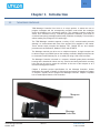
Tough Smart Marquee Message Controller
User Manual
(Manual Part Number MAN-TSM-MSGCT-OO1)
Page | ii
WARNING!!
Programmable control devices such as the Uticor‘s Marquee Message Controller are not fail-safe devices and
as such must not be used for stand-alone protection in any application. Unless proper safeguards are used,
unwanted start-ups could result in equipment damage or personal injury. The operator must be made aware of
this hazard and appropriate precautions must be taken.
In addition, consideration must be given to the use of an emergency stop function that is independent of the
Programmable Controller.
The diagrams and examples in this user manual are included for illustrative purposes only. The manufacturer
cannot assume responsibility or liability for actual use based on the diagrams and examples.
Trademarks
This publication may contain references to products produced and/or offered by other companies. The product
and company names may be trademarked and are the sole property of their respective owners. Uticor
Technology L.P. disclaims any proprietary interest in the marks and names of others.
Manual part number MAN-TSM-MSGCT-OO1
© Copyright 2010, EZAutomation
All Rights Reserved
No part of this document shall be copied, reproduced, or transmitted in any way without the prior written
consent of Uticor Technology L.P.
Uticor Technology L.P. retains the exclusive rights to all information included in this document.
Designed, Built and Marketed
by
Uticor Technology L.P.
4140 Utica Ridge Rd. · Bettendorf, IA 52722-1327
Phone: 1-877-774-EASY · Fax: 1-877-775-EASY · www.uticor.net
Uticor Message Controller
October 2010
Rev 1.0
www.uticor.net
1-877-774-3279
Page | iii
Table of Contents
CHAPTER 1.
1.1
1.2
1.3
INTRODUCTION ................................................................................................................................1-1
THE MESSAGE CONTROLLER ....................................................................................................................................... 1-1
OVERVIEW............................................................................................................................................................... 1-2
QUICK START YOUR UTICOR MARQUEE ........................................................................................................................ 1-3
CHAPTER 2.
MESSAGE CONTROLLER SPECIFICATIONS ...........................................................................................2-1
CHAPTER 3.
MOUNTING AND DIMENSIONS ..........................................................................................................3-1
CHAPTER 4.
WIRING AND CONNECTIONS .............................................................................................................4-1
4.1
COMMUNICATION PORTS AND WIRING ........................................................................................................................ 4-1
4.1.1 Wiring the Power Terminal .............................................................................................................................. 4-1
4.1.2 Wiring the Message Controller to the Programming Computer ...................................................................... 4-1
4.1.3 Wiring the Message Controller to the Marquee .............................................................................................. 4-3
4.1.4 Wiring the Message Controller to the PLC ....................................................................................................... 4-4
4.2
PLC SERIAL INTERFACE CABLES ................................................................................................................................... 4-6
4.3
REPLACEMENT AND OPTIONAL ACCESSORIES ................................................................................................................. 4-6
4.4
THE MESSAGE CONTROLLER INTERFACE ........................................................................................................................ 4-7
CHAPTER 5.
5.1
5.2
5.3
5.4
PROGRAMMING THE MESSAGE CONTROLLER ....................................................................................5-1
ENTER PROJECT INFORMATION ................................................................................................................................... 5-1
ADDING PLC MESSAGES TO THE MARQUEE .................................................................................................................. 5-2
SETTING UP IP ADDRESS AND CREATING A MARQUEE DATABASE ...................................................................................... 5-2
TRANSFERRING PROJECT TO THE MARQUEE MESSAGE CONTROLLER ................................................................................. 5-4
CHAPTER 6.
OPTION BOARDS ...............................................................................................................................6-1
6.1
OPTIONS BOARDS ..................................................................................................................................................... 6-1
6.1.1 Generic DeviceNet I/O ...................................................................................................................................... 6-2
6.1.2 Generic Profibus-DP ......................................................................................................................................... 6-3
6.1.3 Allen-Bradley Data Highway Plus ..................................................................................................................... 6-4
Uticor Message Controller
October 2010
Rev 1.0
www.uticor.net
1-877-774-3279
Page | iv
EU Information
The Uticor Marquee Message Controller is manufactured in compliance with European Union (EU) Directives and carries
the CE mark. They been tested under CE Test Standard #EN55011, and is submitted for UL Certification.
Please Note: Products with CE marks perform their required functions safely and
adhere to relevant standards as specified by EU directives provided they are
used according to their intended purpose and that the instructions in this manual
are adhered to. The protection provided by the equipment may be impaired if this
equipment is not used in accordance with this manual. Only replacement parts
supplied by AVG Automation or its agents should be used.
Programming Software
Onscreen Help
If you are using Uticor Marquee Programming Software, context sensitive
onscreen help is available. To access the Help windows, simply press the F1
function key while on the topic where you need help. For example, if you need
help while working with screens, press the F1 function key while in that
area and a popup window will be displayed. You may also click on the Help
button located in most of the dialog boxes to go to the related help topic.
Technical Support
Although most questions can be answered with this manual, the ToughSmart
Marquee Getting Started Guide or the Uticor Marquee Programming Software
HELP topics, you may additionally find answers to your questions on our web
site @ www.uticor.net. If you still need assistance, please call our technical
support at 1-877-774-EASY or FAX us at 1-877-775-EASY.
SELV Circuits
All electrical circuits connected to the communications port receptacle are rated
as Safety Extra Low Voltage (SELV).
Environmental Specifications
Preventative and
Maintenance Cleaning
Uticor Message Controller
October 2010
Operating temperature: 0 to +60 °C
Storage temperature:
-40 to +60 °C
Operating Humidity:
10-95% R.H., non condensing
Air composition:
No corrosive gases permitted
No special preventative measurement is required
Rev 1.0
www.uticor.net
1-877-774-3279
1-1
Chapter 1. Introduction
1.1
THE MESSAGE CONTROLLER
TSM Message Controller from Uticor is a unique product. It allows the user to
program messages and the corresponding condition under which the messages
should be displayed on a connected marquee. The message controller reads the
values from connected PLC(s), evaluates programmed conditions, and sends to
connected marquee(s) messages which satisfy conditions for display. This is all done
without making any changes to PLC ladder logic.
The TSM Message controller supports a variety of PLC communication protocols
allowing it to communicate with most of the popular PLCs available in the market.
These include serial protocols like Modbus, DF1, DH485 EZ etc, and network
protocols such as Ethernet/IP, Modbus TCP/IP and GE SRTP.
The Message controller can drive one or multiple marquees. A single marquee can
be driven using a 9-pin RS232 port on the message controller. Multiple marquees can
be connected on the Ethernet port, or on serial port using a 232 to 422 converter.
The Message Controller is housed in a compact, industrial grade plastic ventilated
housing and is intended for indoor use only. It has a steel back plate with 4 mounting
holes that can be used to mount the controller on the rear of the marquee or at a
remote mounting panel location.
Chapter 2 provides product specifications for the Message Controller. Outline
dimensions are located in Chapter 3. Wiring and connections are detailed in Chapter
4. Chapter 5 explains how to program the Message Controller. Chapter 6 explains
how to install Option Boards on the Controller.
Marquee
Message
Controller
Uticor Message Controller
October 2010
Rev 1.0
www.uticor.net
1-877-774-3279
1-2
1.2
OVERVIEW
TSM Message Controller has following features:
User programmable Message controller is used with Uticor Slave marquees
The user programs the messages and the corresponding conditions under which messages should be
displayed on connected slave marquees
Messages can be sent to a single marquee, a group of marquees or broadcast
Power up messages (only displayed once) and event triggered messages
Connectivity to most of the popular PLC brands, using serial or Ethernet protocols
TSM Message Controller
FUSE:
LED Indicators:
0.5A, Slow Blow
OFF: No power to unit
GREEN and Red Solid: Unit
working properly
Both RED Solid: Problem
with unit
SETUP Button:
SETUP MODE: Press Once to change
COM1 (9 pin) port to setup mode
confirmed by two beeps. Use TSM
Editor software to talk to message
controller. Press once again to exit
setup mode on COM1 confirmed by a
long single beep.
RESET IP: Press and hold button until
you hear 3 beeps. Wait for few
seconds till you hear 3 beeps again. IP
Address is reset to 192.168.0.1
POWER Input
100-240VAC
50-60 Hz
PLC port :
RS232/422/485 Port, used for
connecting PLCs with Serial
Protocol, such as Modbus RTU,
DF1, DH485, AVG/Uticor PLC
Uticor Message Controller
October 2010
COM1 port:
RS232 Port, used for
Programming Message Controller
Serially (see Setup button),
OR
to connect a slave marquee serially
Rev 1.0
Ethernet:
Can be used for (simultaneously)
Programming Message controller
Connecting Slave Marquee(s)
Connecting PLC(s)
www.uticor.net
1-877-774-3279
1-3
1.3
QUICK START YOUR UTICOR MARQUEE
In this section, we present the steps needed to setup the Message Controller and the Marquee and get
started. This is not intended to explain specific details needed to start-up your system. Rather, it provides a
quick guide to give a broad picture of what is needed to power-up your Uticor Marquee system.
Step 1: Check all System Components
It is always recommended to ensure that you have all the right parts to build your system. This is what you
will need to get started:
Uticor Message Controller
At least one Uticor Slave Marquee ( which supports PMD mode)*
2.5mm blade Screwdriver for wiring
110-250 VAC input Power cord with stripped wires on one end
Programming cable: RS-232C cable P/N: UT-CPG1*, or Ethernet Cable (customer
supplied)
Cable to Connect Slave Marquee to Message controller:
o RS-232C cable with standard 9-pin connector on one (Message Controller) end and
the other end un-terminated (3 stripped wires to connect to the Slave Marquee
terminal strip). P/N: UT-CBL2 OR
o Ethernet cable if slave marquee is equipped with an Ethernet port
PLC Communication cable (See Section 4.2), as required *
Programming Software: Uticor ToughSmartMarquee 1.0 (or higher)*
* These items have to be purchased separately
Step 2: Connect the Message Controller to the PC
The Message Controller can be connected to the Programming Computer serially (using a Programming
Cable: UT-CPG1) or via Ethernet. Refer to Section 4.1.2.
Step 2: Connect the Message Controller to the Slave Marquee
If the PC is not connected to it, the 9-pin COM1 port on the Message controller may be used to connect
serially to a Slave Marquee via RS-232 cable (P/N: UT-CBL2)
You may use an RS-232 to RS 485 Converter to connect multiple slave Marquees serially.
The slave Marquees can also communicate to the Message controller over Ethernet.
Refer to Section 4.1.3 for more details.
Remember: Only one device i.e. the PC or the Marquee may be connected to the 9-pin COM1 port at a
time.
Step 3: Connect the Message Controller to the PLC
You may serially connect the PLC Port on the Message Controller to the PLC‘s COM Port using their
appropriate cables. Refer to Section 4.2 for PLC Serial Interface Cable part numbers and Section 4.1.4 for
wiring info.
The Message Controller may also be connected to the PLC via Ethernet, as long as the PLC supports
Ethernet drivers.
Uticor Message Controller
October 2010
Rev 1.0
www.uticor.net
1-877-774-3279
1-4
Step 4: Apply Power
Connect the power input wires into the Message Controller‘s power terminals. Supply 100-250 VAC Power
to the system, and ensure that the LED indicator at the back turns green. If not, remove power from the
system and check all wiring. Refer to Section 4.1.1 for more information.
Step 5:
Create and Transfer Program to the Controller
Install the Uticor Message Controller Programming Software (P/N: UT-SMPS) on your PC and create a
Marquee Program. Use programming software Help for information on programming. See Chapter 5 for
details.
Transfer Project to the Message Controller via Ethernet. You may also transfer project serially by switching
the Marquee Controller to Setup Mode , if required.
Uticor Message Controller
October 2010
Rev 1.0
www.uticor.net
1-877-774-3279
2-1
Chapter 2. Message Controller Specifications
SERVICE POWER:
100 - 240VAC, 50-60 Hz
ENCLOSURE:
Ventilated enclosure (for indoor use only)
OPERATING TEMPERATURE
0 to +50°C (32 to 122 °F)
STORAGE TEMPERATURE
-40 to +60 °C (13 to +140 °F)
VIBRATION RESISTANCE
5 to 55 Hz, 2g for 2 Hours in X, Y, and Z Axes
SHOCK RESISTANCE
10g for under 12 ms in X, Y, and Z Axes
HUMIDITY
10-95% Non-Condensing
EXTERNAL DIMENSIONS
10.500” (W) x 5.971” (H) x 2.652” (D)
(266.700mm x 151.663mm x 67.361mm)
ELECTRICAL NOISE
NEMA ICS 2-230 Showering Arc, ANSI C37.90a SWC, Level
C Chattering Test
WEIGHT
2.5 lb (1.0 kg)
MOUNTING
Back panel mount using screws
REAL-TIME CLOCK
Not available (Use External PLC clock, if accessible)
COMMUNICATION PORTS
& CONNECTORS
COM1 Port (9-pin D-Sub Female):
Used to program the message controller or to drive
a slave marquee
PLC Port (15-pin D-Sub Female):
- Serial Communication to the PLC
RJ-45 Ethernet connector:
- Ethernet communication to the PLC and the
slave Marquees
- Connect via Ethernet to the Programming PC
Uticor Message Controller
October 2010
Rev 1.0
www.uticor.net
1-877-774-3279
3-1
Chapter 3. Mounting and Dimensions
Outline Dimensions
Units: inches [mm]
Side View
Back View
Uticor Message Controller
October 2010
Rev 1.0
www.uticor.net
1-877-774-3279
3-2
Mounting Dimensions
Notes:
Mount the Message Controller horizontally, and allow at
least 2 inches space all around for proper ventilation.
Use #6 screws for mounting the unit.
Units: inches [mm]
Uticor Message Controller
October 2010
Rev 1.0
www.uticor.net
1-877-774-3279
4-1
Chapter 4. Wiring and Connections
4.1
COMMUNICATION PORTS AND WIRING
4.1.1
WIRING THE POWER TERMINAL
The Message Controller requires a 100250VAC power source. Connect Line1 (HOT)
to L1 on unit. Connect Line 2 (Neutral) to L2 on
unit. GND (on the unit) is connected to the
chassis ground of the cabinet. It is
recommended that you use a power source
that is isolated from relays, valves, etc.
Controller Power Terminal
1
L1
2
L2
3
4.1.2
Pin Function
Pin #
100-250 VAC
Chassis Ground
WIRING THE MESSAGE CONTROLLER TO THE PROGRAMMING COMPUTER
The Message Controller can be connected to the Programming Computer serially
(using a Programming Cable: UT-CPG1) or via Ethernet (Cat5 cable).
Ethernet HUB
Marquee Message
Controller
COM 1
Ethernet
CAT 5 cable
OR
Serial Programming Cable:
UT-CPG1
Programming Computer
running Marquee Software
Uticor Message Controller
October 2010
Rev 1.0
www.uticor.net
1-877-774-3279
4-2
For Serial Communication
The COM1 Port on the Message Controller is used to connect a programming
computer or a slave Marquee to the Message controller via RS-232 protocol only.
The Controller only needs to be connected to a PC when you are programming the
unit. You will use the Uticor Tough Smart Marquee Programming Software (P/N: UTSMPS) to create a message program for the Marquee Controller. You can then
transfer the program to the controller by entering the Setup Mode. A wiring diagram
for the Message Controller Programming Cable (P/N: UT-CPG1) is shown below.
RS-232 Programming Cable (P/N: UT-CPG1)
PC COM Port
CAUTION! Keep the
signal reference GND
wire well protected
from external noise by
using a shielded cable.
RS-232
Controller COM Port
TXD (3)
(3) RXD
RXD (2)
(2) TXD
GND (5)
(5)
DTR (4)
Shell
DSR (6)
CTS (8)
D-Sub 9 pin Male
D-Sub 9 pin Female
For Ethernet Communication
The Message Controller has an RJ-45 port for Ethernet communication. You may
connect this port to the Programming computer using a commercially available Cat5
cable. Then you may proceed to communicate to the Controller (from the PC) by
entering its IP address.
Uticor Message Controller
October 2010
Rev 1.0
www.uticor.net
1-877-774-3279
4-3
4.1.3
WIRING THE MESSAGE CONTROLLER TO THE MARQUEE
The Message Controller can be connected to a single Slave Marquee serially (using
a Marquee Communication Cable: UT-CBL2) or multiple Marquees (using a RS-232
to 485 converter). You can also communicate via Ethernet (Cat5 cable).
Marquee Message
Controller
Ethernet HUB
COM 1
The 9-pin COM1 port only supports RS-232 communication
to one Marquee at a time. Use Comm cable (P/N: UT-CBL2)
Multiple slave Marquees can be connected to the controller
serially by using a RS232 to RS485 converter as shown here
.
Serial RS-232 connection
Ethernet
Cat5 cable
Each slave Marquee on the
Network would have a unique IP
address to be able to
communicate with the Message
Controller
RS 232 to 485
converter
For Serial Communication
The COM1 Port on the Message controller is
also used to connect to the serial port of any
Uticor Slave Marquee that supports PMD mode.
Use an RS-232 cable with standard 9-pin
connector on one (Message Controller) end and
the other end un-terminated (3 stripped wires
(P/N: UT-CBL2) to connect the Marquee Port to
the Communication Screw Terminals on the
Slave Marquee. Since this port does not
support RS-485 connection, you may connect
the Message controller to multiple Slave
Marquees using a RS232 to RS485 Converter.
COM1 Port connector
Pin #
Pin Function
2
(TXD) RS-232C
3
(RXD) RS-232C
5
Logic Ground
For Ethernet Communication
The Message Controller has an RJ-45 port for Ethernet communication. You may
connect this port to the RJ-45 port on the Slave Marquee using a commercially
available Cat5 cable.
Each slave Marquee on the Network should have a unique IP address to be able to
communicate with the Message Controller.
Uticor Message Controller
October 2010
Rev 1.0
www.uticor.net
1-877-774-3279
4-4
4.1.4
WIRING THE MESSAGE CONTROLLER TO THE PLC
You can serially connect the PLC Port on the Message Controller to the PLC‘s COM
Port using appropriate communication cables. Refer to Section 4.2 for PLC Serial
Interface Cable part numbers.
The Message Controller may also be connected to the PLC via Ethernet, as long as
the PLC supports Ethernet drivers.
Marquee Message
Controller
PLC port
PLC 1
RS- 422/ 485
Ethernet
Cat5 cable
Serial connection
(UT-Cx x x)
The 15-pin COM2 port supports RS-232 and
RS 422/485 communication to the PLCs that
support Serial protocols.
Ethernet HUB
Important Note: The Message
controller supports only one
PLC protocol at a time. Hence,
it would only communicate
either Serially or via Ethernet
to the PLC(s).
PLC 3
Each PLC on the Network
would have a unique IP
address to be able to
communicate with the
Message Controller
PLC 4
PLC 2
For Serial Communication
Important Note: The Message controller supports only one PLC protocol at a time.
Hence, it would only communicate either serially OR via Ethernet to the PLC(s) at
any given time.
The Uticor Message Controller has a built-in PLC Com Port. A special Option Board
may be installed for certain PLC protocols. These option boards include: AllenBradley Data Highway Plus, Generic DeviceNet IO and Generic Profibus-DP. All the
boards are installed at the factory. For information on these boards, see Chapter 6.
The Serial PLC COM Port is a 15-Pin Female D-Sub Connector. This port supports
RS-232, RS-422/485 communication.
The table on the following page shows the pinout for the connector.
Uticor Message Controller
October 2010
Rev 1.0
www.uticor.net
1-877-774-3279
4-5
PLC Port Connector
Pin
1
2
3
4
5
6
7
8
9
10
11
12
13
Signal
Chassis GND
TXD
RXD
+5V
Signal GND
LE
CTS
RTS
RXD+
RXDSD+
SDTERM
14
15
N.C.
N.C.
Description
Chassis Ground
RS-232 Serial Data Output
RS-232 Serial Data Input
+5V Through 120 Ohm Resistor
Signal Ground
RS-232 Clear To Send
RS-232 Request To Send
RS-422/485 Serial Data Input +
RS-422/485 Serial Data Input RS-422/485 Serial Data Output +
RS-422/485 Serial Data Output RS-422/485 120 Ohm Termination
Resistor Connect to Pin 9
For Ethernet Communication
The RJ-45 port on the Message Controller can be used for Ethernet communication
to the PLCs that support Ethernet drivers. You may connect this port to the RJ-45
port on the PLC using a commercially available Cat5 cable.
Each PLC on the Network would have a unique IP address to be able to
communicate with the Message Controller
Uticor Message Controller
October 2010
Rev 1.0
www.uticor.net
1-877-774-3279
4-6
4.2
PLC SERIAL INTERFACE CABLES
The Table below provides the Communication Cable part number that is specific to
each PLC.
Cable Description
Cable Part Number
Uticor PLC (via RS-232)
UT-CBL
ADC Direct Logic 15 pin D-shell male to RJ12
UT-CRS2
ADC Direct Logic 15pin D-Shell male to 15pin
D-Shell male
UT-CRS1
GE 90/30 and 90/70 (SNPX protocol )
UT-CGE
AB SLC 5/03/04/05 DF1 port (RS-232C)
UT-CAS1
AB PLC5 DF1 port (RS-232C)
UT-CAP5
AB SLC DH485 port (RS-485A)
UT-CAS4
AB MicroLogix 1000, 1200 & 1500 (RS-232C)
UT-CAM1
Mitsubishi FX Series 15 pin to 25-pin Male port
(RS-422A)
UT-CM1
Mitsubishi FX Series 8-pin MINI-DIN (RS422A)
UT-CM2
Omron C200, C500 (RS-232C)
UT-CO1
Modicon ModBus with RJ45
UT-CM2
Modicon ModBus RTU
UT-CM1
Siemens S7 200 PLC
UT-CS2
Table 4.2 PLC Communication Cables
4.3
REPLACEMENT AND OPTIONAL ACCESSORIES
Uticor Message Controller
October 2010
Accessory
Part Number
Tough Smart Marquee Programming Software
UT-SMPS
RS-232C Programming Cable
UT-CPG1
Replacement ½ AA, 3.6 V Lithium Battery
UT-B
RS-232 Marquee Communication Cable
UT-CBL2
Rev 1.0
www.uticor.net
1-877-774-3279
4-7
4.4
THE MESSAGE CONTROLLER INTERFACE
The Message Controller Interface and its various components are described in this
section:
Status
LED
Fuse
Setup Button
Fuse
This unit uses a 0.5 AMP Slow Blow at 250 VAC, size 2 AG.
Fuse Cap, unscrew to access fuse
for replacement
Side view of unit showing Fuse
Cap location is shown below.
Uticor Message Controller
October 2010
Rev 1.0
www.uticor.net
1-877-774-3279
4-8
Setup Button
Located on the rear of the Marquee Message Controller is the Setup pushbutton.
The Message controller is usually programmed via Ethernet. But, if for some reason
you are unable to do so, then you may press the Setup button when connected to a
programming computer to enter Setup Mode and use the Uticor Marquee
Programming Software to configure Marquee messages serially. This button allows
you to change IP address, download a new user program, or upgrade Marquee
application (firmware) over the serial port.
SETUP MODE
To communicate serially with the Message Controller using the Programming
software running on a PC, follow these steps:
1. Press the Setup Button located on the Marquee Controller Board to enter
―Setup Mode‖. The Message Controller would beep twice to acknowledge
that it‘s in the Setup Mode.
If a Marquee is connected serially to the Message Controller and/or a Group
of Marquees are specified using the Programming software (Setup>Project
Attributes> Status Messages), then those Marquees would display the
following message:
IN SETUP MODE
2. Once in this Mode, you should be able to communicate to the Marquee from
the PC through the programming software. You can check /modify IP
parameters, download a new user program, or upgrade the Marquee
firmware serially.
3. Push Setup Button again to exit the Setup Mode. The Controller would now
send a single long beep to acknowledge that it is exiting the Setup mode.
(Please DO NOT turn off the power for at least 2 minutes to allow the
marquee to save any changes made to its nonvolatile memory). The
Marquee should then start its normal operation and get into run mode.
Disconnect the PC to Message Controller serial connection.
Note: If there are no messages stored in the Message Controller, then the
Marquees would continue to show the “In Setup Mode” message even after
exiting the Setup Mode.
RESET THE IP ADDRESS
If for some reason, you want to reset the IP address of the Message Controller to its
default settings, press and hold the Setup Button (located on the Marquee Controller
Board), for 5 seconds till you hear 3 quick beeps…There is an approx. 5 second
pause, after which you should hear 3 beeps again. This would imply that the marquee
has been set to its default IP address (192.168.0.1)
To assign new Ethernet parameters, enter Setup Mode again and assign the new IP
address serially. You would be prompted to exit the Mode once the parameters have
been set.
Uticor Message Controller
October 2010
Rev 1.0
www.uticor.net
1-877-774-3279
4-9
The Status LEDs
The Status LEDs provides an indication of unit status. They will illuminate as RED or
GREEN.
If the LEDs do not light up, this indicates that there is NO POWER to unit or the
power supply failed. Check the power source and the fuse. If ok, send unit back to
factory for repair.
If the LEDs turn RED and stay RED, it indicates a unit failure. If this happens, return
the panel to the factory for service.
If one LED turns RED and the other turns GREEN, it indicates normal operation.
Lithium Battery
How to Replace the Battery:
BEFORE REMOVING BATTERY, back up the user program and
save it using the Uticor Marquee software.
Typical battery life is 5 years.
a. Connect Message Controller to a computer and save the user program to
disk.
b. Disconnect the power source.
c.
Open back cover (shown open in figure below) to access the battery.
d. The battery is located in the upper-left hand corner as shown in the figure
below. Remove old battery and replace with a new 1/2 AA, 3.6 V Lithium
Battery (Part Number: UT-B).
e. Close rear cover and ensure that the door latches.
f.
Reconnect power source, connect to PC, run Marquee Programming
Software, and follow instructions in Ch.5 to transfer the user program that
was previously saved to disk.
Battery
Uticor Message Controller
October 2010
Rev 1.0
www.uticor.net
1-877-774-3279
5-1
Chapter 5. Programming the Message Controller
The following example demonstrates how to create a project a Message Controller communicating to an AB PLC via
Ethernet IP protocol.
5.1
ENTER PROJECT INFORMATION
Open the Uticor ToughSmartMarquee programming software. The following dialog box appears:
1. Click
to create
a new
Project
3. Select
your
Marquee
type
2. Enter
Project
name
5. Click to
Set PLC
Attributes
4. Select PLC Type and
protocol
Entering Project information:
1. On the Project Information screen, click on the Edit Program OFF-LINE (Write to Marquee Later) button.
2. Under Project Name, enter the name of the project. The file has a ―.tsm‖ suffix.
3. Select your Marquee Type- Power Marquee or Tough Smart Marquee
4. Click on the DOWN arrow to the right of PLC Type and Protocol to view the list. In this example, select
EZ PLC (Ethernet TCP/IP) – Connecting to an EZ PLC via Ethernet TCP/IP protocol.
5. Click on the View/Edit PLC Com Setup to edit the PLC attributes. The PLC Attributes dialog box
applicable to the type of PLC selected in Step 4 above, will appear. Here you can make changes to the
PLC communication setup.
Uticor Message Controller
October 2010
Rev 1.0
www.uticor.net
1-877-774-3279
5-2
6. If communicating over Ethernet, ―Add PLC Details‖ along with its Ethernet IP, gateway, Subnet masks etc.
Click on OK to save the changes or ‗Help‘ to view the help topics available for that particular PLC.
7. Now that you have entered the project information, click OK to save the project. You may click on
Clear to clear the Project details and start over. Exit can be used to quit without saving the Project.
5.2
ADDING PLC MESSAGES TO THE MARQUEE
The Uticor Marquee software allows you to program different Marquee Messages, based on the tag values
in the PLC. You can program Active or Inactive Messages based on whether the PLC tag condition is
fulfilled on not. Refer to the ―Add Messages‖ index in the Marquee software Help section for a detailed
explanation on setting up Marquee Messages. Power Up Messages can only be sent to a particular
Marquee if it is grouped and assigned in the Marquee Database.
5.3
SETTING UP IP ADDRESS AND CREATING A MARQUEE DATABASE
1. CONFIGURE ETHERNET PARAMETERS:
The Message Controller‘s Ethernet parameters can generally be programmed through the PC using the
Controller‘s Ethernet port. But, under certain cases, serial port COM1 may also be used to configure the
same:
a. Via Ethernet connection between the Message Controller and the PC
In the Marquee software‘s Main programming window, Click on menu Marquee >Ethernet Setup
Read the current Ethernet settings from the Message Controller.
You can also configure the following Ethernet Parameters: IP Address, Subnet Mask, and Gateway
Address and write them to the Controller.
Uticor Message Controller
October 2010
Rev 1.0
www.uticor.net
1-877-774-3279
5-3
b. Via Serial connection between the Message Controller and the PC:
If, for some reason, you are unable to communicate over Ethernet, you can try communicating to the
Message Controller over the Serial port (COM1) instead and then change the Ethernet IP parameters
using the Programming Software.
To do so, connect serially to the Message Controller and enter the SETUP Mode. Using the Marquee
software, change the PC to Marquee connection to ―Serial‖.
Next, bring up the Ethernet Setup Dialog box and assign new IP settings to the Message Controller.
Once that occurs, you would be prompted to exit the Setup Mode.
Resetting the IP address to its default value.
If for some reason, you want to reset the IP address of the Message Controller to its default settings,
press and hold the Setup Button (located on the Marquee Controller Board), for 5 seconds till you hear
3 quick beeps…There is an approx. 5 second pause, after which you should hear 3 beeps again. This
would imply that the marquee has been set to its default IP address (192.168.0.1)
You may then proceed to assign new IP parameters either via Ethernet or by entering SETUP Mode
again and assigning the new IP address serially. You would be prompted to exit the Mode once the
parameters have been set.
2. CREATING A MARQUEE DATABASE
Each Slave Marquee is assigned a unit address using the Dip switches located at the back of the marquee
unit. A unit address is programmed into each message to specify which unit or units should display that
message. The IP address for the slave Marquees is initially assigned using separate Slave Marquee
Programming software.
Each unit address consists of two identifiers—a Group and a Unit Number. A group may contain up to
4095 slave units, connected serially or via Ethernet to the Message Controller. The unit addresses allow
the ToughSmart Master Marquee or Message controller to select and send messages to select slave
Marquee units.
The slave Marquees with certain
group and unit numbers can be
grouped together using the Uticor
TSM Marquee software.
Click on menu Setup ->Marquee
database. A dialog box pops up.
Enter the IP addresses/unit
numbers for the slave marquees
and create Marquee Groups that
would contain multiple slave
units.
Please Note: In the Add Marquee
dialog box, Communication mode
implies the connection between
the Message controller and the
slave Marquee.
Uticor Message Controller
October 2010
Rev 1.0
www.uticor.net
1-877-774-3279
5-4
5.4
TRANSFERRING PROJECT TO THE MARQUEE MESSAGE CONTROLLER
Green, when
Marquee is
connected to the
PLC, else Red
Message Controller
or ToughSmart
Marquee’s Ethernet
IP address
1. In the Main programming window, Click on menu File ->Transfer to Marquee to send the
Messages to the Marquee Message Controller.
2. A dialog box appears as shown above
3. Enter the Marquee Message Controller‘s IP address and press ‗Start‘.
Uticor Message Controller
October 2010
Rev 1.0
www.uticor.net
1-877-774-3279
6-1
Chapter 6. Option Boards
6.1
OPTIONS BOARDS
Option Card Installation Instructions
The option cards available for the Message Controller are Allen-Bradley Data
Highway Plus, Generic DeviceNet I/O and Profibus-DP. If specified when placing an
order, your Marquee Message Controller would be shipped with the appropriate
option card pre-installed. A connector, unique to each card, is attached to these
option boards and is accessible from the bottom of the Marquee Message Controller.
The option card is installed into the backplane connector (shown below) of the
Marquee Message Controller unit. (The connector on the bottom right side of the card
installs into the backplane connector.) The card is secured with two screws.
Option Card is installed into the
Backplane connector as shown here
62-PIN SOCKET MOUNT
BEHIND THE OPTION CARD
Uticor Message Controller
October 2010
Rev 1.0
www.uticor.net
1-877-774-3279
6-2
6.1.1
GENERIC DEVICENET I/O
The DeviceNet I/O Option Card has a special connector that is accessible from the
bottom of the unit.
The DeviceNet connector extends over the edge of the board. Next to the connector
are DIP Switches and then four LEDs that illuminate to indicate status. The Watchdog
LED is only visible when you open the access door.
Devicenet Connector
Watchdog LED
Dip Switches
Status LEDs
Connector Pin
Signal
Description
1
V-
Negative supply voltage
2
CAN_L
CAN_L bus line
3
SHIELD
Cable shield
4
CAN_H
CAN_H bus line
5
V+
Uticor Message Controller
October 2010
Positive supply voltage
Rev 1.0
www.uticor.net
1-877-774-3279
6-3
6.1.2
GENERIC PROFIBUS-DP
The Profibus-DP Option Card has a special connector that is accessible from the
bottom of the unit.
The Profibus-DP connector extends over the edge of the board. Next to the
connector are a Termination Switch, Rotary Address Switches, and four LEDs that
illuminate to indicate status.
Profibus-DP Interface
Termination
Switch
Address
Switches
FieldBus Connector (9-pin Female D-Sub)
D-SUB
Screw Terminal
Name
Housing
Shield
1
Not connected
-
2
Not connected
-
3
B-Line
4
RTS
5
GND BUS
Isolated GND from RS-485 side*
6
+5 V BUS
Isolated +5 V from RS-485 side
7
Not connected
8
A-Line
9
Not connected
Indicator Lights
Connected to PE
Positive RxD/TxD according to RS-485
specification
Request to Send*
Negative RxD/TxD according to RS485 specification
-
* +5V BUS and GND BUS are used for bus termination. Some devices,
like optical transceivers (RS-485 to fiber optics) might require external
power supply from these points. RTS is used in some equipment to
determine the direction of transmission. In normal applications only ALine, B-Line, and Shield are used.
Uticor Message Controller
October 2010
Rev 1.0
www.uticor.net
1-877-774-3279
6-4
6.1.3
ALLEN-BRADLEY DATA HIGHWAY PLUS
The Allen-Bradley Data Highway Plus Option Card has a special connector attached
that is accessible from the bottom of the unit.
The option card has been connected to the backplane connector on the message
controller unit. (The connector on the bottom right side of the card installs into the
backplane connector.) The card is secured with two screws.
The Allen-Bradley Data Highway Plus PLC connector extends over the edge of the
board. Next to the connector are two LEDs that illuminate to indicate status.
AB DH+
Connector
Configuration
“Error” LED
Transmit
Enable LED
AB DH+ Option Card Outline
62-PIN SOCKET MOUNT BEHIND
THE OPTION CARD
DH+ Connector on the
Marquee Controller‘s
Option Board
1 Blue
DH+ Connector on
the Allen Bradley
PLC
1
Shield
Shield
2 Clear
2
Uticor Message Controller
October 2010
Rev 1.0
www.uticor.net
1-877-774-3279
[a]
Uticor Message Controller
October 2010
Rev 1.0
www.uticor.net
1-877-774-3279