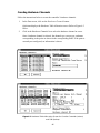
1
Network Service Tool IV User's Manual Introduction ............................................................... 1 Installation and Start-up ........................................... 5 Utilities ...................................................................... 21 Carrier Controls ...................................................... 31 On-line ...................................................................... 55 Quickstart ................................................................. 61 BEST ++ ................................................................... 73 BEST ........................................................................ 75 Report Configuration .............................................. 77 Address Search ........................................................ 81 Diagnostic Trace ...................................................... 83 Network Diagnostics ................................................ 91 Comfort System Software ....................................... 97 CCN Database Utilities ........................................... 99 DOS Prompt ........................................................... 111 Exit .......................................................................... 113 Appendixes ............................................................. 115 This document is the property of Carrier Corporation and is delivered on the express condition that it is not to be disclosed, reproduced in whole or in part, or used for manufacture by anyone other than Carrier Corporation without its written consent, and that no right is granted to disclose or so use any information contained in said document. Carrier reserves the right to change or modify the information or product described without prior notice and without incurring any liability. © 2002, Carrier Corporation Printed in U.S.A. 808-562 Rev. 02/99 Hayes is a registered trademark of Hayes Microcomputer Products, Inc. Windows is a registered trademark of Microsoft Corporation. DataVue is a registered trademark of DataVue Computer Systems. Opto 22 is a registered trademark of Opto 22. B&B is a registered trademark of B&B Electronics. ii Manual Revisions The Network Service Tool IV User’s Manual is catalog number 808562, Rev. 2/99. It replaces the Network Service Tool IV User’s Manual, Rev. 3/98. The following describes the revision made to this manual. Section/Chapter Changes Appendix A Revised model number and supplier information under RS-485 Interfaces. iii iv Introduction Introduction About this Manual Purpose The Network Service Tool IV User’s Manual is intended to be used as a guide to the various Service Tool functions by individuals who have completed CCN training and are CCN certified. It provides you with information necessary to understand and use the various Service Tool functions. Its Structure and Contents To help you locate the information you need, the structure of this manual follows the Service Tool’s menu structure. The menu items from the Service Tool’s Main Menu comprise most of the manual’s chapter titles. These Main Menu items include Utilities, Carrier Controls, On-Line, Quickstart (Comfort Controller), BEST++ Programmer's Environment, BEST Programmer's Environment, Report Configuration, Address Search, Diagnostic Trace, Network Diagnostics, Comfort System Software, CCN Database Utilities, DOS Prompt, and Exit. Note: If you have installed Carrier's Comfort System software on your Network Service Tool computer, you will have the capability of launching it from the Main Menu. Because this item is not part of the Network Service Tool software, however, its operation is not included in this manual. For information on Comfort System, refer to the 33CS Carrier Comfort System Operating Instructions Catalog No. S33-30S (Form 33CS-2SO). Conventions Used in this Manual The Network Service Tool IV User’s Manual is designed to help you to find information quickly and easily. The combination of text and illustrations in the manual is intended to give you accurate information in an understandable format. Paragraphs that document a menu item in the Service Tool generally consist of an overview of the menu item followed by procedural information. Overview paragraphs are introduced by the heading About (Menu Item Name). In documenting the menu item Points, for example, the overview information is introduced with the phrase About Points. The procedural paragraphs are introduced with the phrase Once you’ve picked (Menu Item Name). For example, the procedural information for the item Points is introduced with the phrase Once you’ve picked Points. 1 Functions and Features The Network Service Tool is a Carrier Corporation product designed to provide you with an interface to the Carrier Comfort Network (CCN) and CCN equipped HVAC equipment, either locally or through a telephone line. The Service Tool software is designed to be installed on a portable PC with a hard drive. The various Service Tool functions are presented using a branching menu structure with short, descriptive menu items displayed on the screen. A brief description of each Service Tool function is included here. Using Utilities, you can: • • • • • import and export databases. change the Service Tool’s comm port, modem settings, address, and communication baud rate. select Building databases. connect to remote buildings via a modem. test the dial out capability of connected Autodial Gateways. Using Carrier Controls, you can: • • • • • • • monitor, configure, and make changes to controllers, systems, groups, and software options. add new controllers, systems, and groups to the active database. send time, date, holiday, and daylight savings information to controllers. perform a cold call to obtain a building directory from an NDS module and broadcast an Update-Poll command. adjust the point display update rate. view a device’s Alarm History file. view alarms received from the network. Using the On-line function, you can: • directly access Comfort Controller memory, thus eliminating a lengthy Carrier Controls upload or download and expediting the Comfort Controller configuration process. Using the Quickstart function, you can: • directly access Comfort Controller memory, expediting the Comfort Controller database creation process. 2 Using the BEST++ function, you can write custom control programs for applications in which the required control sequence does not match any resident algorithm. BEST++ is a user-friendly, English-based programming language. Programs are created with a Service Tool, then compiled and downloaded to a Comfort Controller. Although BEST++ is a user-friendly language, only people who have received proper training should attempt to write BEST++ programs. Some features of BEST++ are as follows: • • • menu-driven programming environment. full screen text editor. automatic syntax checking. In the CCN, a BEST++ program is downloaded to a Comfort Controller and is commanded to run there. Although resident in a Comfort Controller, the program can access system variables from any BEST-compatible system element as long as the element is on the same bus. Using the BEST function, you can write custom control programs for applications in which the required control sequence does not match any resident algorithm. BEST is a user-friendly, English-based programming language. Programs are created with a Service Tool, then compiled and downloaded to a FID. Although BEST is a user-friendly language, only people who have received proper training should attempt to write BEST programs. Some features of BEST are as follows: • • • menu-driven programming environment. full screen text editor. automatic syntax checking. In the CCN, a BEST program is downloaded to a FID and is commanded to run there. Although resident in a FID, the program can access system variables from any BESTcompatible system element as long as the element is on the same bus. Using the Report Configuration function, you can: • • • • add a new or modify an existing consumable, runtime, or history report table. add a new or modify an existing Data Collection or Tenant Billing Option or NDS Module. delete an existing report table, Tenant Billing or Data Collection Option, or NDS Module. add or remove a Data Collection Option. 3 Using Address Search, you can: • • • • • • • check communications with a specified element. search a network for active elements. determine the address, model, and software version number of an element. enter a name, description, location, serial number, and reference number into an element’s ID table. change an element’s address. set primary and secondary communication baud rates. make a device a broadcast acknowledger, bridge, or non-bridge. Using Diagnostic Trace, you can: • • • • collect data from CCN system elements. generate a printout of the data. save trace data for future use. start or stop the trace based on the status of a discrete point, value of an analog point, or time of day. Using the Network Diagnostics function, you can: • • • • • monitor all CCN Communication Bus activity. monitor activity to and from a selected system element. display and print previously saved monitor data. identify the network’s broadcast and alarm acknowledgers, and time broadcaster(s). identify duplicate addresses. Using the Comfort System Software function, you can launch into this option. Comfort System Software is not a part of the Network Service Tool software, and its operation is not included in this manual. Using the CCN Database Utilities function, you can: • • • convert individual or directories of controller database files between Service Tool and ComfortWORKS file format. export and transfer ComfortWORKS files to and from diskette. initialize the Comfort Controller. Using the DOS Prompt function, you can launch any DOS-based programs that may be installed on your Network Service Tool computer. For example, TCU factory test software. Using Exit, you can go to the Windows® Program Manager if used in Windows 3.1 or Windows 95. 4 Installation and Start-up Installation and Start-up Service Tool Hardware When you order the Service Tool, you receive a kit, as described in Appendix A. In addition to the hardware provided in the kit, you must provide a PC, an RS-232/RS-485 interface and, in some cases, cable adapters. To connect to remote buildings using telephone lines, a Hayes®-compatible modem is required. A list of all approved hardware is also included in Appendix A. RS-485 Interfaces An RS-485 interface is required in order to communicate with CCN products. If your PC has an expansion slot, the interface can be installed internally. The Opto 22™ AC24AT adapter card has been tested and approved for use in this application. See Appendix B for information on strapping and installation of the Opto 22 card. Caution: Note: When the Opto 22 card is used, it is assigned COM2. If you have any other device (such as an internal modem) assigned to COM2, it must be removed. Opto 22 cards should only be used on desktop PCs. If you are planning to run the Service Tool from a machine that does not have an expansion card slot, the RS-232 serial port must be converted to RS-485 by an external device. We recommend B&B™ Model 485COR or, as an alternative, B&B™ Model 485LPCOR, which is described on Page 6. The B&B converters require an adapter to mate to the CCN interface cable and, if your PC has a 9-pin serial port, another adapter to mate to your PC. These adapters are also available from B&B. See the section in this manual on interface cables for more information on these adapters and Appendix A for information on ordering the B&B converters and adapters. An alternative to the B&B converter is the CCN Repeater module (HK50AA014). Refer to the CCN Contractor’s Manual (808-710) for instructions on using the Repeater as an RS-232/RS-485 converter. The Service Tool also has the ability to connect to CCN networks via a phone line if the remote network is equipped with an Autodial Gateway. To accomplish this, use a 100% Hayes-compatible modem. A list of Hayes compatible modems that are approved for use with the Service Tool is given in Appendix A. If a modem is not listed in Appendix A, use the Utilities function to modify your modem’s configuration strings to allow your modem to communicate with the Network Service Tool. 5 Alternate RS-485 Converters B&B Electronics offers several RS-485 converters. These converters are powered from the RS-232 port on the computer. Because these converters are powered from the RS-232 port, you can run your Service Tool completely stand alone without any AC power if your portable computer is battery powered. You will not require a power supply (B&B™ Model 485PS) for this converter. If your portable PC has a 9-pin serial port, however, you will require a 9-to-25-pin DShell converter (B&B™ Model 232CAMS). Model 485COR, Model 485LPCOR: To use these converters with the Service Tool interface cables, you must order the special 25-to-9-pin converter (B&B™ Model CARJB) or make your own 25-pin D-Shell connector to connect it directly from the B&B converter to the CCN Communication Bus. Follow the wiring instructions below from the RS-485 side of the converter: CCN Data Positive (Red) = Pins 14, 16, and 17 jumpered together CCN Signal Ground (White) = Pin 7 CCN Data Negative (Black) = Pins 2, 3, and 5 jumpered together Model 485CARLP, Model 485CARLP9: To use these converters with the Service Tool, there is no need to use the Service Tool cable set. Using a standard RJ-11 phone cord, you can connect directly to a Comfort Controller's phone jack connector. To connect to CCN controllers that do not have an RJ11 connector, you can make a custom cable also using a 4-pin standard RJ-11 phone cord and the following instructions: Hold the phone cable with both RJ-11 connectors in your hand such that the RJ-11 connectors extend upward and the locking tabs that hold the connectors in place are facing away from you. Identify the RJ-11 connector that has the following colored RJ-11 colored wires from left to right: Black, Red, Green, Yellow. Cut off this RJ-11 connector, strip, and terminate the RJ-11 colored wires to the apppropriate CCN wires according to the chart below: RJ-11 Pin # 1 2 3 4 RJ-11 Color Black Red Green Yellow CCN Color Red (Data +) White (Signal Ground) Not Used Black (Data -) 6 CCN Interface Cables The following cables are available for use with the Service Tool. These cables can be ordered as separate parts from Carrier. Main Cable This is the ten-foot main interface cable needed to connect the Service Tool to the various CCN devices. It has a 9-pin male D-shell connector on one end and two 4-position connectors (plug and header) on the other. Element Adapter Cables Three adapter cables are also available to allow quick and easy connection to the various CCN elements. They attach to the end of the Main Cable. The FID Adapter is used to connect the Service Tool to FIDs. It has a 4-pin connector on one end and two 7-position connectors (plug and header) on the other. A LID3 (HH51BX001) is a space temperature sensor with an override button and communication port. The LID3 Adapter is used to connect the Service Tool to the comm port on the LID3. It has a 4-pin connector on one end and a modular telephone RJ-type connector on the other. The Universal Adapter is equipped with alligator clips for use with system elements in which the communication port (labeled COMM PORT) connector is not easily accessible. Adapters for the B&B Converter If you elect to use the B&B RS-232 to RS-485 converter some adapters are required. These adapters are used to connect the B&B converter to the PC and the Main Cable. Depending on the PC you have chosen, one or both of these adapters will be necessary. See Appendix A for ordering information. RS-232 Adapter (B&B RS232CAMS) This is a 9-pin female to 25-pin male RS-232 adapter that mates the B&B converter to PCs that have 9 pin RS-232 ports. This adapter is required by all approved PCs. RS-485 Adapter (B&B CARJB) This is a 9-pin female to 25-pin female RS-485 adapter that mates the B&B converter to the Main Cable and is required any time the B&B converter is used. For reference see Carrier drawing CEDP 121365-01. 7 Software Installation Before You Begin Network Service Tool IV will run under DOS (3.3 or greater), Windows 3.x, or Windows 95. You must have at least 5 Mb available on the target drive for the install to succeed. The Service Tool program comes on two 3.5" diskettes, labelled A and B. The Service Tool is best installed on a substituted drive of its own, which you can create with the SUBST command in DOS. To create a substituted drive, follow these steps: 1. If you are using Windows 3.x or 95, open a DOS window. If you are installing on a DOS system, skip to step 2. 2. At the command prompt, select the actual drive on which Service Tool will be installed by typing x: where x stands for the letter of the selected drive. 3. If necessary, type cd \ to move to the root directory of the drive. 4. Type md \service to create a subdirectory for the Service Tool. 5. To create the substitute drive, type subst s: x:\service where s stands for the letter you’ve chosen for the substitute drive and x is the drive where you just created the service subdirectory. 6. Edit the AUTOEXEC.BAT file to include the line subst s: x:\service so that whenever you start your computer, the substitute drive will be created (again, replace s and x with the values you’ve chosen for your system). Continue with the steps in the next section. Installation Process After completing the preparatory steps in the previous section, follow these steps to install the Service Tool: 1. If you are using Windows 3.x or 95, open a DOS window. 2. Place the first installation diskette in drive A: and type a:\sinstall s: where s is the letter of the substituted drive you created in the previous section. 3. Follow the on-screen instructions and place the second installation diskette in drive A: when prompted to do so. The installation program will transfer a number of files and ask you to set some system parameters, including some that change the appearance of the screen. In most cases, the default settings will be correct. If some information cannot be read clearly, try to adjust the screen intensity and/or contrast settings on the PC itself before making any modifications to the foreground or background settings. Note: You can return to these decisions in the future by exiting from the Service Tool to DOS (Function C) and typing SSETUP. 8 4. Once the system parameters have been established, you will be prompted to set the PC communication port configuration. You will be asked two questions. Select comm port [1-4] for local CCN: Select comm port [1-4] for modem connection to CCN: Enter the proper values, or press the Escape key to accept the defaults. 5. If you are installing the Service Tool on a DOS system, skip to step 7. If you are installing on a Windows 3.x or Windows 95 system, type exit to return to the Windows desktop. 6. Run the program S:\HVAC\SETUP.EXE. In Windows 3.x, use the File|Run command in the Program Manager. In Windows 95, run this program from the Start menu. The Setup program will create a program group and install an icon from which the Service Tool can be launched. It will also update the SYSTEM.INI file so that the CCN communications driver will be correctly launched. If you are using Windows 3.x, the proper icon may not be automatically associated with the Service Tool. To enable the supplied icon, click once on the Service Tool program item, then press Alt+Enter key combination to bring up the properties dialog. Click on the Change Icon button, select OK, and select OK again. The Service Tool icon should now be present. 7. Reboot the computer before using the Service Tool. Special Considerations for Windows Users Do not place the Service Tool icon in your Startup folder. When starting Windows or when your system is booting up, make sure that Windows completely finishes its start-up procedures before trying to run the Service Tool. Under some circumstances, you might see the error messages Out of environment space or Bad command or file name when starting up the Service Tool. This is most likely due to not having sufficient environment space allotted during system boot. The following line should be included in the CONFIG.SYS file if such a problem occurs: shell=c:\command.com c:\ /p /e:2048 The value 2048 may need to be increased depending on what other programs are installed on a given computer. Also, on Windows 95 systems, the following change to the SYSTEM.INI file will be made for modem support. The line device=*vcd will be changed to: device=ccnvcd.vxd ;device=*vcd 9 Using the Service Tool To use the Service Tool most effectively, you should understand how it is structured. The information you need for proper understanding of the Service Tool is contained in the following paragraphs. The Access Key A valid access key is required for the Service Tool and is provided in the Service Tool kit. This key looks like an RS-232 adapter but contains a special code that the Service Tool software will look for. If this key is not properly installed, the Service Tool Main Menu will appear but most functions will not operate. Plug the access key into the parallel (printer) port of the PC before accessing any of the Service Tool functions. Printing is not affected by the access key. Starting the Service Tool To start the Service Tool from DOS, type SERVICE at the C> prompt, or from Windows double click on the Service Tool icon. Selecting the Communication Mode The Service Tool can be configured to connect directly to a network or to communicate with a remote network via a modem. Selection of the communication mode is done during start-up. As the Service Tool is being loaded, you are asked: Do you want to use the modem port for the Service Tool? Answer this question, Yes, to tell the Service Tool that this session is going to connect to the network via a modem. All communications are then directed to the port configured for modem communications. If this question is answered, No, communication is directed to the port configured for direct communication. Note: This question does not appear if both direct and remote communications were assigned to the same communication port during installation. To check your port configuration go to the DOS prompt (Function C from the Main Menu) and type SET. Errors in comm port assignment can be corrected by selecting Utilities from the Main Menu and then Driver. Once the communication port question is answered, the computer will enter an initialization process. When the Service Tool Main Menu appears (Figure 2-1), the Service Tool is ready for use. 10 ============================================================. .Service Tool Menu — Service Tool Version 2.10 . . . . . . . . . . . . . . [1]Utilities [2]Carrier Controls [3]On-Line [4]Quickstart [5]BEST++ [6]BEST [7]Report Configuration [8]Address Search [9]Diagnostic Trace [0]Network Diagnostics [A]Comfort System Software [B]CCN Database Utilities [C]DOS Prompt [D]Exit . Select item by number or letter:___ ============================================================= Figure 2-1 Service Tool Main Menu Communicating Directly to a Network (Local Connect) During start-up, answering the modem port question, No, tells the Service Tool that it will be connected directly to a CCN network or device. This can be done using the Opto 22 adapter card, the B&B converter, or a Repeater Module. • Using the Opto 22 Adapter Card The Opto 22 RS-485 adapter card can be permanently installed in the expansion slot of your PC. See Appendix B for instructions on installation. The CCN interface cable is then plugged into the 9-pin connector on the card. • Using the B&B Converter If an expansion slot is not available, the RS-232 to RS-485 conversion can be done external to the PC using the B&B 485COR. Plug the B&B converter into the serial port of your PC. Note: If your PC has a 9-pin serial port connector, an adapter (B&B RS232CAMS) is required. Attach this adapter to the converter before plugging it into the PC. 11 Attach the 25-to-9 pin RS-485 adapter (B&B CARJB) to the other side of the converter and connect the interface cable to it. Plug the converter’s power pack into an appropriate source and you are ready to connect to the CCN network or element. • Using the Repeater Module An alternative to the B&B converter is the CCN Repeater (HK50AA014). Refer to the CCN Contractor’s Manual (808-710) for instructions on using the Repeater as an RS-232/RS-485 converter. Setting the Communication Speed 1. Select the Utilities function from the Main Menu. 2. Select Driver from the Utilities menu. 3. The current baud rate is displayed on the screen. 4. If necessary, modify the baud rate entry to match the network or device (typically 9600). 5. Press F2 to set the baud rate. The Service Tool will set itself to this baud rate automatically each time it is booted up. Interface Cables The Service Tool’s main interface cable is designed for use with PIC and CIO Modules and terminates with 4-position connectors. If you are not connecting to a PIC or CIO, choose the appropriate adapter from the kit and attach it to the end of the main interface cable. You are now ready to connect to the CCN network or element. • Connecting to the Network at a System Element The easiest place to connect to a CCN network is at a system element. Remove the bus connector from the element’s COM1 port and plug the Service Tool cable’s male connector into the bus connector. Connect the cable’s female connector to the system element’s COM1 port. • Connecting to the Network at a Local Interface Device (LID) Built into the LID3 Space Temp Sensor is an RJ-type (modular telephone) connector. This can be used to connect the Service Tool to the network using the LID3 adapter. Attach the LID3 adapter to the end of the Main Cable. Plug this into the mating connector on the LID3 Space Temp Sensor. 12 Communicating with a Remote Network (Modem Connect) To connect to remote installations via telephone lines, a Hayes-compatible modem is required at the local end and an Autodial Gateway must be present at the remote location. The communication speed must be set to match the modem, not the network port, in this situation. Setting Communication Speed and Dial Type for a Modem Connect 1. Select Utilities from the Main Menu. 2. Select Driver from the Utilities menu. 3. The remote communication port, remote baud rate, Service Tool address and dial type is displayed on the screen. 4. If necessary, modify the current settings. Check your modem manual for the correct baud rate. Check your phone system for the correct dial type. 5. Press F2 to save the settings. The Service Tool will set itself to these settings automatically whenever remote operation is requested. Establishing the Telephone Link 1. Select Utilities from the Service Tool Main Menu. 2. Select Building from the Utilities menu. 3. Select Connect. 4. Type the number of the desired building and press Enter. For information on adding buildings to the building list, refer to the Utilities chapter of this manual. 5. Press the F2 key to initiate the phone call. 6. When the link is successfully established, a Connection Established message will appear. 7. Select Quit to return to the Service Tool Main Menu. Importing a Building Database In order for you to access a CCN system element, the element in question must be present in a building database, otherwise known as the Carrier Controls List (CC List). The CC List can be created on the spot or imported from a disk. The Service Tool can support up to 100 separate Building databases each identified by a Building Number and a Building Name. 13 Selecting A Building Before creating a new database first select a new building. To select a building: 1. From the Service Tool Main Menu select Utilities. 2. Select Building. 3. From the list of buildings (00-09) identify an unused building number. 4. If 00-09 are all used, select Browse to continue through the range 10-99. 5. For a local CCN, select Database then enter the building number. Note: For a new local CCN, first select Modify, enter the site information, and press F2. Then select Database. The name of the current database will be listed at the bottom of the screen. 6. For a remote CCN, select Connect then enter the building number, phone number and password and press F2 to connect. Databases that have been previously saved using the Utilities function's Export menu item can be recovered using the Import operation. Databases associated with building names can be selected. Caution: Unless the current database is saved using Export, it will be lost when another database is Imported. When importing a database, select a new building number. To import a database: 1. Select Utilities from the Service Tool Main Menu. 2. Select Import. 3. Follow the prompts on the screen to complete the import procedure. Once the import is complete, select Quit to return to the Main Menu. Select the Carrier Controls function to display the new database. Creating a Building Database in the Field If you are not importing a database, certain information must be determined before a database can be created. This information includes the address (bus and element number) of each element. An element’s address can be determined a number of ways including reading it off the element itself. Unfortunately, many times this is not practical, especially if you are connecting over a phone line. In these situations, element addresses can be determined by using either the Cold Call operation in Carrier Controls or the Service Tool Address Searcher. 14 Cold-Call If the network contains a Network Directory Services (NDS) Module, it can be interrogated to provide the CC List for the site. Caution: Be sure to switch to a new building before performing Cold-Call. To initiate a Cold-Call: 1. From the Service Tool Main Menu, select Carrier Controls. 2. Select Directory. 3. Select Cold-Call. 4. Type Y for yes and press Enter to initiate a Cold-Call. The Cold-Call function will request the Carrier Controls List from the NDS Module. When the Cold-Call is complete, the Carrier Controls List is re-displayed with the names and addresses of all controllers known to the NDS Module. For more information on the Cold-Call function, refer to the Carrier Controls chapter of this manual. Address Search If the element is not part of a network or an NDS Option is not available, element addresses can be determined using the Address Search function. 1. From the Main Menu select Address Search. 2. If you have any hint as to bus or element number, use Find to enter a starting address. Otherwise, select Up. The Address Search will poll the network, address by address, starting at the entered address. When a valid response is seen, the search stops and information about the responding element is presented on the screen. Part of this information is the bus and element number. Invoking the Up function will continue the search at the next higher address. Using the Address Search function, you can compile a list of elements residing on the network. For more information on Address Search, refer to the Address Search chapter of this manual. A Special Case Address 0, 0 Newer CCN system elements have an added feature that makes address determination easier. These modules will answer a poll to Bus 0, Element 0. For you to use this feature, the element in question must be disconnected from the network. 15 Caution: Do not attempt to use this feature without detaching the element in question from the network. 1. From the Main Menu select Address Search. 2. Select Find. 3. Enter 0 for bus and element number. 4. Press the F2 key. The Address Search will poll for Device 0, 0. If a valid response is seen, information about the element (including its address) is presented on the screen. If the element is of older design or inoperative, the message No device found will appear. Adding Elements to a Building Database Once an element’s address is known, it can be added to the CC List, uploaded, and viewed. Note: Cold-Call will automatically add all known system elements to the CC List. If Cold-Call was used to create the CC List, select the desired element and proceed to Step 5. 1. Select Carrier Controls from the Main Menu. 2. Select Add. 3. Select Controller. 4. Enter a name, description, and location for the element as well as its address. 5. The element now appears highlighted in the Carrier Controls List. 6. Select Upload to add the element’s configuration tables to the database. The Service Tool will prompt you for confirmation before starting the upload process. Type Y and press Enter to begin uploading. Type N to abort the process. Once the upload is complete, the controller is in your database. See the Carrier Controls chapter for further instructions on the various Service Tool functions now available. 16 Before You Start Using the Service Tool Interpreting the Display Screens Most Service Tool screens are displayed in the format shown. CONTROLLER/SYSTEM/GROUP ============================================================= Points Modify Remove Diagnostic Controller-Time Quit Makes changes to configuration. the controller, system or group ============================================================= Name —————— AH317 Description ——————————— FEEDS 3RD FLR WEST Location ———————— WEST ROOF Address ——————— 0 4 AH217 FEEDS 2nd FLR WEST MER258 0 7 DC/DT DATA COLL,DATA XFER MER258 0 100 O DATACOL DATA COLLECTION MER258 0 100 O DXFER DATA TRANSFER MER258 0 100 G EXHAUST EXHAUST FANS BLDG 1 SHOP S AH101 WEST SHOP MER136 S WEST_EXH WEST SHOP EXHAUSTERS MER136 FID100 WEST SHOP MER136 0 10 BLDG21 GATEWAY FOR BLDG 21 MER136 0 50 ------------------------------------------------------------CARRIER CONTROLS 11:30:00 30 Feb-90 Figure 2-2 Sample Display Screen The topmost line of data on the screen is called the current data line and contains data specific to the Main Menu item you have selected. Below the current data line of a Service Tool display are two lines of data contained in what is called the command window. The menu items that you select and the prompts to which you respond are contained in the command window. It also includes a one-line description for each menu item that you highlight in the command window. In this manual, items appearing in bold type indicate the selected or activated command; for example Modify in Figure 2-2. The middle of the display shows the requested data in a list format. Along the bottom of a Service Tool display is a line of data called the status line, which contains the name of the currently selected item along with time and date. 17 Selecting from Menus Service Tool operations are accessed using menus. These menus can be thought of as a tree with many branches. To complete a task, you may need to access a number of menus in a sequence determined by the function’s structure. In some cases you may also be prompted for responses to questions displayed on the screen. These prompts generally require a yes or no response, which you can signify by typing the letter Y for yes, or the letter N for no followed by the Enter key. The items on the Service Tool Main Menu are selected by number or letter. Simply type the number or the letter of the desired function and press the Enter key. Items in menus other than the Main Menu can be selected two ways. The first method is to highlight the desired menu item using the direction keys and then press the Enter key. Alternately, typing the first letter of the menu item selects the item. Selecting from Lists You can search through a list to select the item you want by pressing the up or down direction keys. This highlights an item. Move the highlight to the desired item and press the Enter key to complete your selection. The Home, End, Page Up, and Page Down keys can also be used to scan through a list rapidly. Speed Searching Speed Searching provides a means of searching for an item in a list. The approach is particularly useful with long lists, when using the up or down direction keys to search through a long list would be time-consuming. Note that not all lists offer speed searching. To know whether the speed search can be used with a list, look for a small box above the list’s column headers in the upper left portion of your screen. The Carrier Controls List is one in which you will see the Speed Search Box. To use the Speed Search, type the name of the item in the Speed Search Box. With each letter you type, the Service Tool will automatically locate and highlight the first item in the list that begins with the letter(s). You can switch to using the direction keys at any time. When the item you want is highlighted, press the Enter key to complete the selection. 18 Keys that Perform Special Functions This section describes the Service Tool's special function keys. The Esc [Escape] Key To retrace the steps you have taken or the menus you have chosen in reverse order, you can use the Escape key. Press the key once for each reverse step or menu. The F1 [Help] Key When installed on a hard drive, the Service Tool has two levels of user help: one-line and full-page. • A one-line description of a highlighted menu item is displayed in the command window beneath the menu item. • A full-page help message can be displayed for any highlighted menu item (other than items on the Main Menu) by pressing the F1 key while the item is highlighted. The F3 Key When in the Carrier Controls function, the F3 key allows access to the description and location fields of the display. To change a description or location, highlight the item to be modified and press the F3 key. Enter the new description or press Enter to skip to location without altering the existing description. Pressing Enter again completes the process. The F4 Key When in the Carrier Controls function the F4 key allows you to change controller and select point names. Highlight the name to be modified and press the F4 key. Type the new controller or point name and press Enter. Warning: If a point has been entered in any network options (such as Data Transfer), the point name must be changed in the option as well or the function will no longer operate correctly. The F5 Key Any time a list or a configuration, maintenance, or service configuration screen is being displayed in Carrier Controls, pressing the F5 key will send the entire list to the printer port. This also applies to the On-line Configuration function. The F6 Key The F6 key can be used to upload a controller’s “description” and “location” from the controller’s memory to the Service Tool’s CC list. To do this, highlight the controller while the CC list is being displayed and press the F6 key. The information will be read from the controller’s memory and added to the CC list. 19 The F7 Key The F7 key can be used to quickly input data into certain configuration tables. The availability of speedy data entry is indicated on color monitors by the presence of green shading on a decision. For black and white monitors, the presence of speedy data entry is indicated by a darker grey shading. Position the cursor on the highlighted decision and press F7. From the list displayed, select the controller table, point, sensor group, algorithm, or schedule name you wish to insert into the configuration decision. Then, press Enter. 20 Utilities Utilities UTILITIES | +————+————-+——————+—————+—————+—————+———-—+ | Export | Import | Driver | Modem | | | Building Hangup Gateway | +———-+————-+———-——+———-—+ | | | | | Browse Modify Connect Database Quit | Quit Figure 3-1 Utilities Function Map General Information The Utilities function allows you to: • • • • • • • • export or save a building’s database. import a previously exported database. erase the building database currently in use. change the Service Tool’s address, comm ports, and communication speeds (baud rate). establish communication to a remote site using a modem. terminate modem communication with a remote site. test the dial out capability of your Autodial Gateway. configure modem strings. After you have selected Utilities, the following menu is displayed: SERVICE TOOL UTILITIES ================================================================ Export Import Driver Modem Building Hangup Gateway Quit Export configuration to disk/directory ================================================================ Figure 3-2 Utilities Menu This chapter covers each of the Utilities menu items, including an overview and the important procedural information about each. 21 Export allows you to save the active database onto a floppy disk or into a backup directory of a hard drive. This allows you to save a database for each location or customer to be imported in the future. Import replaces the active database with one that was previously exported. Driver allows you to change the Service Tool’s address and communication speed (baud rate) and to specify the type of phone line (tone/pulse). Modem allows you to configure setup strings for modem control and test the modem response to these strings. Building allows you to create and access a list of buildings and building databases. Connecting to a remote building requires a name, phone number, and password. Phone number and password must match the information entered in the Autodial Gateway of the remote site. Hangup tells the modem to hangup, breaking the connection to a remote site. Gateway gives you the ability to test the dialout operation of local Autodial Gateways. Quit returns you to the Main Menu. Export About Export: Export allows you to save the Service Tool’s active database onto a floppy disk or into a backup directory of the hard drive. This allows you to create a separate database for each location or customer. You can also use this menu item to copy a Service Tool database to a Carrier Building Supervisor. Once you’ve picked Export: You are prompted for a drive to which the current database will be copied. Users have the option of exporting to a floppy (A drive) or the hard drive. Once a drive has been entered, you are prompted for a building name. If you will be importing this database to a Building Supervisor, press Enter (Do not enter a name). Otherwise, type a building name. You are then asked to verify the drive and building name. Typing Y and pressing Enter will begin the export procedure. Caution: All existing files for the specified building name will be deleted. If you are exporting to a floppy disk, write the building name on the disk label once the export is complete. Follow these instructions if you are planning on importing the database to a Building Supervisor. After the export is complete, enter DOS and create a subdirectory called REPORTS in the root directory (at the A> Type MD REPORTS) on the database backup disk. This gives the database disk the proper subdirectories needed to perform an import to a Building Supervisor. 22 Import About Import: Import allows you to erase the current database or replace it with one that was previously exported to a floppy disk or a backup directory on the hard drive. Once you’ve picked Import: You will be prompted for a drive and building name of the database you wish to import. Users have the option of importing from a floppy (A drive) or the hard drive. If you are unsure of the building name, typing DIR *. from the DOS root directory will display a list of all directories. Exported databases will appear as subdirectories in the root directory. The directory name is the building name given to it during the export. Warning: Note: Unless it has been previously exported, the current database will be lost. If you wish to save the current database for future use, use Export before importing or switch to a new building. A database that was exported from a Building Supervisor can be imported to a Service Tool with a hard drive. When you import a database exported from a Building Supervisor, do not type the building name when prompted to do so. Instead, press the Enter key. Once you enter the drive and building name you are asked to verify them. Typing Y and pressing Enter will begin the import procedure. To Erase the Current Database It is possible to erase the database in a particular building. This is done by importing a “blank” database. This database is supplied with the Service Tool under the building name BLANK. When prompted for a drive type C. When prompted for a building name, type BLANK. Driver About Driver: Driver is used to set the address and baud rates of the PC. The Network Service Tool supports different ports and baud rates for local (direct) and remote network (modem) connection. Once you’ve picked Driver: The menu in Figure 3-3 is presented. Use the Enter key to move between fields. Type the desired settings in the appropriate fields. Press F2 to save, or press Esc to escape without altering the original settings. 23 SERVICE TOOL UTILITIES ============================================================= Modify data; Press F2 to save and setup driver. ============================================================= Service Tool Driver Setup Bus Number: Element Number: Local Port: Local Baud Rate: Remote Port: Remote Baud Rate: Dial:(Pulse = 0, Tone = 1) 0 231 1 9600 2 9600 0 Figure 3-3 Driver Menu Bus Number For most situations, the bus number can be left at 0 except if you are attempting to communicate from a secondary bus to an element on another bus. For proper communication in this situation the bus number of the Service Tool must be set to the bus to which it is physically connected. Allowable entries are 0-240. Element Number Allowable entries for an element number are 1-240. Element number 231 is reserved for use by the Service Tool. Local Port If you are directly connecting to a CCN network, use this field to enter the number of the PC communications port through which you are communicating. Local Baud If you are directly connecting to a CCN network, use this field to enter the network speed (typically 9600). Baud rates above 9600 are not currently supported and are for future use. Remote Port If you are remotely connecting to a CCN through a modem, use this field to specify the PC communications port to which the modem is connected. 24 Remote Baud If you are remotely connecting to a CCN through a modem, use this field to specify the modem baud rate. This baud rate will become the default baud rate for all modems. It can, however, be overridden on a building by building basis using the Utilities function's Building, Modify commands. Dial The value entered indicates the dialing method performed by the modem making the call. Pulse dialing is the method performed by rotary dial telephones. Tone dialing is the method performed by most keypad-equipped telephones. The allowable entries are 0 (Pulse) and 1 (Tone). Modem About Modem: Modem gives you the capability to modify the displayed default modem configuration strings which allow the Network Service Tool to communicate with your local modem. The default strings are for a 100% Hayes Smartmodem-compatible modem. If you are not using this type of modem, you must modify these default strings. Once you've picked Modem: The Service Tool Modem Setup screen is presented. Type the desired settings in the appropriate fields. Press F2 to send the new settings to the modem. Setup String 1 to 4 Use these four strings to modify the configuration of your local modem. The command entered in this decision must be part of the Hayes AT command set. For a list of these commands, refer to your modem user's guide. Call From # The string of characters that you enter here will be included in the connection message that is displayed. This will assist remote building personnel in identifying the remote caller at the remote Autodial Gateway modem. Dial Prefix Enter any strings that you would like to be automatically dialed before each remote modem phone number that you specify using the Utilities function's Building command. For example, certain telephone systems may require you to dial 9 or 8 before an outside telephone number. 25 Dial Suffix Enter any strings that you would like to be automatically dialed after each remote modem phone number that you specify using the Utilities function's Building command. For example, calling card number. Diagnostic Test Entering a 1 in this field will cause the Network Service Tool to perform a modem test. The message Testing Modem and the specific modem command strings will be displayed as shown. Note that the display of 0 following each command string indicates a successful test of each string. String 4 must return 0 in order for dialing to proceed. Anything other than 0 indicates an error with the string. --> Modem String 1 <-- 0 --> Modem String 2 <-- 0 --> Modem String 3 <-- 0 --> Modem String 4 <-- 0 The message Testing Complete displays on completion. Building About Building: Building displays a list of up to 100 buildings (CCNs) that you can access using the Service Tool and a modem, if necessary. Each building has a name, location, phone number, and password associated with it. Once you’ve picked Building: The Building list is displayed with a new command menu. BUILDING =============================================================== Browse Modify Connect Database Quit Connect to a remote building via modem =============================================================== 1 2 3 BldgName -------WestBldg TR4lab Location -------------30 Carrier Way 10 Research Dr Password -------Black2 Green2 Figure 3-4 Building List Screen 26 Dial String -----------3325 3322 Browse About Browse: Browse allows you to cycle through the list of all buildings in the Network Service Tool's database. Once you've picked Browse: The building name, location, password and phone number is displayed for the next ten buildings in the Network Service Tool's building list. Press Enter to view each consecutive set of buildings. Modify About Modify: Modify allows you to change the information shown for a building. Once you’ve picked Modify: You are prompted for a Building number (00-99) and then given access to a building’s name, location, phone number, password, and baud rate. Building name can be up to 8 characters (letters and numerals only) long. After you modify a name and press F2, the message New building name detected. Create a new building? will be displayed. Answer Y if you are adding a new building to the database. Answer N if you are modifying an existing building's name. Remote location can be up to 24 characters long. Any ASCII character (letters, numerals, and punctuation) can be entered. Phone number can be up to 60 characters. Hyphens (-) may be included in the number, but are not necessary. Typing a comma between numbers will cause a pause to occur during dialing. This may be necessary in some PBX networks where a pause is required to get an outside line. Password can be up to 8 characters (letters and numbers only) and must match a standard password of the Autodial Gateway at the remote building. If a remote baud rate is set in the Remote Baud field, it overrides the remote baud rate that is specified using the Utilities function's Driver menu item. If Remote Baud is left at the default setting (0), the remote baud rate specified in the Service Tool Driver Setup configuration will be used. Connect About Connect: Connect allows you to pick a remote building (CCN) from the list and establish a communication link to an Autodial Gateway via modem. Once you’ve picked Connect: You are asked to enter a building number (00-99). Type the number of the desired building and press Enter. The current network name, location, phone number, password, and baud rate for the site is displayed and can be modified if necessary at this time. Press F2 to attempt to establish the remote link. Once the link is established, the message Modem Connect will appear in the lower left corner of the screen. 27 If the message modem not responding appears, check the Service Tool’s Remote Baud rate (under Driver). The baud rate must be acceptable to the modem. This message can also be caused by incorrect port assignments. Check the port assignment (under Drives). The current port assignments are displayed. The message remote modem not responding indicates either a wrong phone number, the line is busy, or a faulty modem at the remote site. If the password entered is wrong, the message incorrect password will be displayed. Caution: If the telephone connection is broken, the modem connect indication that appears in the lower left corner of the screen will change to modem disconnect. Depending on the function currently active, you may also see the message Comm Failure- Periodic retries in progress. In either case you must return to the Utilities function and reconnect to reestablish the telephone link. Database About Database: Database gives you the ability to load a different building's (CCN's) database. Each building's database is stored in a separate subdirectory on the Network Service Tool's hard drive. You can load a database without connecting to a remote building or without performing an import/export. Once you've picked Database: You are prompted for a building number (00-99). The Network Service Tool will save any currently active database and load the selected buildings database from the Network Service Tool's hard drive. The name of the currently active database will be displayed in the bottom line of the screen. Quit Quit returns you to the Utilities menu. Hangup About Hangup: Hangup breaks the telephone connection to the remote building. Warning: If the connection is broken for any reason the Service Tool will not reconnect automatically. Gateway About Gateway: You can use this menu item to check the operation of a locally connected Autodial Gateway. 28 Once you've picked Gateway: You are prompted to enter the system element number of the locally connected Autodial Gateway. Be sure that the Autodial Gateway's OCCPHNE and UNOCPHNE Tables have been properly configured with the correct phone numbers and passwords. You are now prompted for an offset number (0-15). Enter the number of the Autodial Gateway OCC_PHNE or UNOCPHNE Table that contains the Autodial Gateway phone number and password that you wish to call. Enter the number of the table that is currently in effect (occupied or unoccupied). This number is displayed in the top line of the configuration table screen in the format PHONE NUM #-X, where X represents the offset number. The message, Waiting for completion from Autodial Gateway, is displayed during the test. Successful test completion is indicated by the message, Network Connection Established. Quit Quit returns you to the Service Tool Main Menu. 29 30 Carrier Controls Carrier Controls General Information The Carrier Controls function enables you to perform the following tasks to manage a network’s controllers, systems, groups, and software options: • • • • • • • • Monitor, configure, and make changes to controllers, systems, groups, and software options Add new controllers, systems, and groups to the active database Send time, date, holiday and daylight savings information to controllers Perform a cold-call to obtain a building directory from an NDS module Adjust the screen update rate of point displays Display a list of network alarms View a device’s Alarm History file View alarms received from the Network Controllers are the CCN elements with addresses and configuration tables. Controllers perform the actual HVAC monitoring and control operations. The Carrier Comfort Network can contain several types of controllers. These include PICs, FIDs, and Comfort Controllers. A system is usually a subset of the points in a controller. Defined by the operator, a system typically forms a single unit of control. For example, a FID that contains more than one air handler can be divided into several systems, each a separate air handler. A display group usually contains similar points from many controllers. A group can provide such information as space temperatures or fan statuses. Options are special purpose software programs that do not provide direct control. Options include such things as Data Transfer, Data Collection, Loadshed, and the CHILLERVISOR System Manager (CSM). Carrier Controls Menu Structure Selecting Carrier Controls from the Service Tool Main Menu produces the following screen. On this screen is a list of all controllers, systems, and options listed in the database for this building. This list is known as the Carrier Controls List. A new menu is also produced. A brief description of each function of the new menu is given on the following page. 31 GLOBAL FUNCTIONS ============================================================== Select Add Building-Time Directory Update-Rate Net-Alarm Exit Allows you to select a controller, system, group, or option ------------------------------------------------------------- O O G S S Name ———— AH317 AH217 DC/DT DATACOL DXFER EXHAUST AH101 WEST_EXH FID100 BLDG21 Description ————————————————— FEEDS 3RD FLR WEST FEEDS 2nd FLR WEST DATA COLL,DATA XFER DATA COLLECTION DATA TRANSFER EXHAUST FANS WEST SHOP WEST SHOPEXHAUSTERS WEST SHOP GATEWAY FOR BLDG 21 Location ———————— WEST ROOF MER258 MER258 MER258 MER258 BLDG 1 SHOP MER136 MER136 MER136 MER136 Address ——————— 0 4 0 7 0 8 0 8 0 8 0 10 0 12 Figure 4-1 Carrier Controls List Select allows you to choose one of the controllers, systems, groups, or software options from the entire CC List. Use Add to include a controller, system or group into the Carrier Controls List. You can add options once the controller containing the options is added to the data base. Building-Time allows you to send the time of day, date, day of week, and holiday status to all controllers. When Building-Time is selected, the Service Tool clock is displayed. Press F2 to transmit this data to the network. If the displayed time is incorrect, refer to the manual supplied with your PC to set the correct time. Directory allows you to get a list of all known devices in the network. Update-Rate allows you to change the speed at which the Service Tool display is updated. Net-Alarms allows you to display the last 50 alarms that were received when Carrier Controls was running. Exit returns you to the Service Tool Main Menu. Select About Select: Select allows you to choose from the systems, groups, and software options listed in the Carrier Controls List. An example of such a list is shown on the following page. 32 ============================================================ Name Description Location Address ———— ——————————— ———————— ——————— AH317 FEEDS 3RD FLR WEST WEST ROOF 0 4 AH217 FEEDS 2nd FLR WEST MER258 0 7 DC/DT DATA COLL, DATA XFER MER258 0 100 O DATACOL DATA COLLECTION MER258 0 100 O DXFER DATA TRANSFER MER258 0 100 G EXHAUST EXHAUST FANS BLDG 1 SHOP S AH101 WEST SHOP MER136 S WEST_EXH WEST SHOP EXHAUSTERS MER136 FID100 WEST SHOP MER136 0 10 BLDG21 GATEWAY FOR BLDG 21 MER136 0 50 Figure 4-2 Carrier Controls List The name, description, location, and address of each listed item is displayed. The letter S in front of a name on the list denotes a system, usually a set of related points from one controller. The letter G denotes a group of points, usually a set of related points from various controllers. The letter O denotes a software option. Name is used by system options to locate various devices. To modify the name of a controller, system, or group, press the F4 key. Names can be up to 8 alphanumeric (letters and numbers) characters long. Note: Spaces are not allowed in names. Description and location are 24 character fields that allow the user to display additional information about the controller, system, group, or option. To modify the description and location of a controller, system, or group, (but not of an option) press the F3 key. The address of a device is displayed on the right hand edge of the display screen. This address consists of two numbers, bus and element. In Figure 4-2, all the elements are on Bus 0. Note that systems and groups do not list addresses. This is because the systems and groups can consist of points from more than one controller. Note also that options show the address of the controller in which they reside. Once you’ve picked Select: Move the highlight using the cursor control keys until the desired device is highlighted and press Enter. The selected device will remain highlighted, the description and location of the selected device will appear in the upper portion of the screen, and a new command menu will appear. Figure 4-3 is an example of the display screen with device AH217 selected. If you have a large number of devices in your CC List, Speed Search can be utilized. Instead of using the cursor control keys, type up to eight letters. With each letter you type, the Service Tool automatically locates and highlights the first item in the CC List that begins with the letter or sequence of letters. When the desired item is highlighted, press the Enter key to complete the selection. If no match is found, the Service Tool will highlight the closest match available. The cursor control keys can then be used to continue the search manually. 33 CONTROLLER/SYSTEM/GROUP ============================================================= Graphic Points Modify Remove Diagnostic Ctrl-Time Quit Views list of points for the controller, system, or group ------------------------------------------------------------FEEDS 2nd FLR WEST MER258 Name ———— AH317 AH217 DC/DT O DATACOL O DXFER Description Location ——————————— ———————— FEEDS 3RD FLR WEST WEST ROOF FEEDS 2nd FLR WEST MER258 DATA COLL, DATA XFER MER258 DATA COLLECTION MER258 DATA TRANSFER MER258 Address ——————— 0 4 0 7 0 8 0 8 0 8 Figure 4-3 Selected Device Screen Each menu item shown here is covered in a separate section of this chapter. A brief description of each function is included here. Graphic is not supported by the Service Tool. Selecting Points produces a list of available data including live (i.e., real-time) data from the selected device. Modify gives you direct access to all the tables present in a selected controller or to the points list of a selected system or group. Remove allows you to delete the selected device from the database. Remove will ask you to verify the command. Press Y and Enter if you do wish to delete the specified item. Diagnostic gives you access to the service and maintenance tables as well as VerifyConfig. Controller-Time allows you to view and set the clock functions in the selected device. These functions include time of day, date, day of week, holiday status, and daylight savings status . The clock of the selected device is read and displayed. Type over any incorrect data and press F2 to send the information to the controller. If the clock is correct, press Esc to exit Controller-Time. Select/Points About Points: Points is used to display the actual (i.e., real-time) data from the controller, system, or group you chose using Select. An example of a points display from a FID is shown on the next page. 34 LIST POINT COMMANDS ============================================================== Force Auto Services Quit Select from list with enter key ============================================================== FEEDS 2nd FLR WEST MER258 DESCRIPTION ——————————— Supply Fan Status Supply Fan Space Temp Cooling Coil Valve Heating Coil Valve STATUS —————— ON Start 72.0 F 12.0 PSI 16.0 PSI SUPV POINT ————— SUPFS SUPF SPTMP CCVLV HCVLV Figure 4-4 Points Display Once you’ve picked Points: The points contained in the controller, system, or group selected are displayed with a new command menu (shown in Figure 4-4). Included in the points display of any controller, system, or group is the following information. A single point can be selected for further action by highlighting the desired point and pressing Enter to activate the menu. Note: Some devices contain more than one display table. With these devices you will need to select from a list of display tables before getting the points list. If the device you chose has no real-time data, you will see a message stating No display tables present. The description of the controller, system, or group (from the Carrier Controls List) being displayed is shown in the upper left corner. The controller location appears in the upper right corner. In this example, the data for AH217 is being displayed. A brief (up to 24 characters) description of the point’s function is displayed in the first column. Point descriptions can be altered by pressing the F3 key and entering the desired information. Caution: Point Descriptions in PICs should not be altered. The point’s dynamic value including force code is displayed in the second column. Refer to the section on Forcing Points for more information on force codes. Note that for all points, symbols, may be displayed, blinking next to a point’s status in the table. The letter C means a failure has occurred. This could be a failure of a sensor or loss of communications to the module. An asterisk (*) means that the point is in alert or alarm. The symbol @ means that an internal failure has occurred. The letter U is used by Parker devices to indicate an undefined point. The point’s software name, up to 8 characters long is displayed in the third column. Point names in FIDs can be modified by pressing the F4 key and entering the desired information. 35 The controller where the point originates (system and groups only) is displayed. Once you’ve selected a point : The point description is displayed on the top of the screen. The point remains highlighted and the command menu is activated. In Figure 4-5 the supply fan has been selected. Supply Fan - SUPF #2 LIST POINT COMMANDS ============================================================== Force Auto Services Quit Forces highlighted point to specified value ============================================================== FEEDS 2nd FLOOR WEST MER258 DESCRIPTION -----------------Supply Fan Status Supply Fan Space Temp Cooling Coil Valve Heating Coil Valve STATUS --------------ON Start 72.0 F 12.0 PSI 16.0 PSI POINT ---------SUPFS SUPF SPTMP CCVLV HCVLV Figure 4-5 Selected Point Screen The following functions are available once a point has been selected: Force allows the live status or controlling algorithm of selected points to be overridden. Auto allows the operator to clear a force from a point. When a force is removed, the point is returned to algorithm control and the actual status of the point is displayed. Services gives access to the configuration, maintenance data, time schedule, and setpoints of a point in a FID, and to configuration and maintenance data available in VVT Gateways. It is also the method for instituting a Submaster Force. Select/Point/Force About Force: Force allows the live status or controlling algorithm of selected points to be overridden. Depending on the device, certain points are not forceable. If so, a message stating that a force is not allowed for the point will appear when a force is attempted. Once you’ve picked Force: The current status of the selected point is displayed in the command window near the top of your screen as shown in Figure 4-6. 36 Supply Fan SUPF # 2 LIST POINT COMMANDS ============================================================== Press Enter to validate entry; Press F2 to transmit START Enter force value: ============================================================== FEEDS 2nd FLOOR WEST MER258 DESCRIPTION ———————————— Supply Fan Status Supply Fan STATUS ——————— ON Start POINT ————— SUPFS SUPF Figure 4-6 Force Command Window To force an analog point, type the desired value and press Enter. To force a discrete point, use the spacebar to toggle the displayed status then press Enter. Press the F2 key to transmit the Force command to the controller. Select/Point/Auto Use Auto to clear a force from a point. Each time an Auto command is issued, the highest level force will be cleared. If any lower level forces are in effect, the next highest force is displayed. When all forces have been removed, the point is returned to algorithm control. Force Codes Points can be forced through a number of methods besides a Service Tool command. Once a point is forced, a force code will appear in the point display to indicate where the force originated. If the force was instituted via the Service Tool, the word Service appears. 37 The following is a list of force codes along with their meanings: Table 4-1 Force Codes Force Code Fire Safety Service SUPVSR Monitor Min-off OWNER CONTROL LOAD XFER SUBMAS NTER NTFC BEST TEMP Description Forced by Fire Alarm System Forced by Internal Safety Override Forced by Service Tool Forced by Building Supervisor or ComfortWORKS Forced by Off-site Building Supervisor or ComfortWORKS Forced by Minimum Offtime Algorithm Forced by Owner’s Module (FID only) Forced by System Option Forced by Loadshed Option Forced by Data Transfer Option Submaster Reference Force (FID only) Permissive Interlock Force (FID only) Nighttime Free Cooling Force (FID only) Forced by B E S T Forced by Temperature Override Algorithm Select/Point/Services About Services: Point Services are available for FIDs and VVT Gateways. With a FID controller, Point Services will allow you to display and modify the selected point’s configuration, maintenance data, controlling time schedule, and controlling setpoint schedule; and to create Submaster Reference forces. With a VVT Gateway, Point Services allows you to display and modify point configuration and maintenance data only. Once you’ve picked Services: A new command menu listing the available items is displayed. Note: Some devices may not accommodate individual Point Services. If so, the menu item is inactive. 38 Supply Fan SUPF # 2 FID POINT SERVICES ================================================================ Point-Config Time-Sched Setpoints Maintenance Reference Quit Accesses configuration for the highlighted point =============================================================== Figure 4-7 Point Services Menu Point-Config gives access to the configuration decisions for the selected point. Loop gains, alarm limits, and display type are examples of the sort of information found in Point-Config. Time-Sched gives access to the time schedule that the point algorithm uses to determine if the Occupied or Unoccupied setpoints are to be used. Setpoints allows access to the controlling setpoint schedules for the selected point. Maintenance gives you access to additional data such as force codes, alarm status, and other internal algorithm calculations for the selected point. Reference allows the user to enter a fixed value for the submaster reference of an analog output algorithm in a FID. Doing so overrides the master loop portion of the algorithm. Note: Some points do not require all the tables described here. If the point does not use a table, it either does not appear in the menu or a message stating table not available will be given. Point/Services/Point-Config, Time-Sched, Setpoints, and Maintenance About these items: These items are used to view or change the configuration data of a point in a FID or VVT Gateway. Warning: Do not trust the data that first appears on the screen. This information is obtained from the Service Tool’s database for the point and may be old data. Always update the Service Tool’s database using Upload and Save before making modifications. If you make any changes remember to upload to the resident Building Supervisor’s or ComfortWORKS database. Once you’ve picked any of these items: The data for the selected point is displayed and the command menu shown in Figure 4-8 appears. 39 Space Temp - SPTMP # 3 MODIFY CONTROLLER CONFIG ============================================================== SAVE UPLOAD DOWNLOAD COPY EDIT QUIT Modify data; Press F2 to activate menu ============================================================== FEEDS 2nd FLOOR WEST Analog In Config MER258 Figure 4-8 Point Configuration Menu The data requested is displayed on the screen. Changes to the displayed data are made by moving the cursor to the data to be changed and typing over the old data. Pressing the Esc key will return the last saved data to the display. For further information on any system element's configuration decisions, refer to the subject system element's overview and configuration manual. Pressing F2 activates the command menu and the following functions. When PointServices is in use, the description of the selected point (Space Temp in this example) appears on the top of the screen. Save transfers the data that is on the screen to the database disk. Warning: This does not change the operation of the point. The new data must be downloaded to the controller to effect a change. Upload transfers the data from the FID to the display screen. Warning: Uploading does not change the data on disk (the database) for the point. The uploaded data must be saved to update the database. Download transfers the data from the screen to the FID. Note: To keep the Service Tool database current, always save any changes you have made. Remember to upload to the resident Building Supervisor’s or ComfortWORKS database. Copy allows you to copy the data from another similar table instead of reentering the same data. Once you’ve selected Copy: You are presented with a list of like tables that exist in this controller. For instance, if a time schedule was displayed when you invoked the copy command, you would be presented with a list of all the time schedules in the controller. Using the cursor control keys select the table you wish to copy and press Enter to complete the command. The original screen is displayed with the copied data. The data can now be downloaded to the controller and saved to the database. Edit will save the current screen and return the cursor to the data field if the command menu has been activated (F2). 40 Point/Services/Reference About Reference: Reference is short for Submaster Reference Force. The Submaster Reference Force allows you to enter a fixed value for the Submaster Reference of an analog output algorithm in a FID. Doing so overrides the Master Loop portion of the algorithm. Refer to the UT203 FID Overview and Configuration Manual for more information on Submaster Reference Force. Once you’ve picked Reference: The current submaster reference of the selected point is displayed in the command window near the top of your screen as shown in Figure 4-9. Cooling Coil Valve - CCVLV # 4 FID POINT SERVICES ================================================================ Press Enter to validate entry; Press F2 to transmit force value Enter submaster reference value: 78 F ================================================================ FEEDS 2nd FLOOR WEST MER258 DESCRIPTION -----------------Supply Fan Status Supply Fan Space Temp Cooling Coil Valve Heating Coil Valve STATUS ---------------------ON Start 72.0 F 12.0 PSI 16.0 PSI POINT ----------SUPFS SUPF SPTMP CCVLV HCVLV Figure 4-9 Reference Force Command Window To initiate a Submaster Reference Force, type the desired Submaster Reference value and press Enter. Press the F2 key to transmit the force command to the controller. The word SUBMAS will be displayed next to the status meaning a Submaster Reference Force is in effect. Note that the psi output still fluctuates. This is because the inner loop of the algorithm is still running, providing the desired output. Use Auto to clear a Submaster Reference Force. When a Submaster Reference Force is autoed, the Submaster Reference is calculated by the Master Loop portion of the analog output algorithm. Note: Because the Master Loop runs once every two minutes, there may be a delay before a new Submaster Reference is generated. 41 Select/Modify (Controller) About Modify: Once a controller is selected, Modify gives you direct access to all tables available in the controller. If a system or group has been selected, Modify allows you to add or delete items from the Points List. Once you’ve picked Modify: A new command menu showing the functions available is produced. The command menu for Modify Controller is shown in Figure 4-10. MODIFY CONTROLLER ================================================================ Time-Sched Setpoints Graphic Ctrlr Names Upload Dwnload Quit Access to controller’s time schedule(s) ================================================================ FEEDS 2nd FLOOR WEST MER258 O O G S S NAME -------AH317 AH217 DC/DT DATACOL DXFER EXHAUST AH101 WEST_EXH DESCRIPTION -------------------FEEDS 3RD FLR WEST FEEDS 2nd FLR WEST DATA COLL, DATA XFER DATA COLLECTION DATA TRANSFER EXHAUST FANS WEST SHOP WEST SHOP EXHAUSTERS LOCATION -----------WEST ROOF MER258 MER258 MER258 MER258 BLDG 1 SHOP MER136 MER136 ADDRESS --- --0 4 0 7 0 8 0 8 0 8 Figure 4-10 Modify Controller Screen Selecting Time-Sched produces a list of all the time schedules available in the controller. Select a schedule for modification by moving the highlight to the desired schedule and pressing the Enter key. Selecting Setpoints produces a list of all the setpoint schedules available in the controller. Select a schedule for modification by moving the highlight to the desired schedule and pressing the Enter key. Graphic is not supported in the Service Tool. Selecting Controller produces a list of all tables available in the selected device. Refer to the individual controller documentation for more information on these tables. Names allows you to change the names of the various tables available in the selected device. Upload transfers all table data from the controller to the database. Download transfers all table data from the database to the controller. Note: Remember to upload the database from the controller to the resident Building Supervisor or ComfortWORKS after downloading from the Service Tool. 42 Select/Modify (Controller)/Time Schedule About Time Schedule: Each time schedule consists of seven periods, eight day flags, and an occupied and unoccupied (start and stop) time for each period. This flexibility allows for each day to have its own schedule or, by using the day flags, several days can use the same times. Figure 4-11 shows a sample time schedule. Warning: Do not trust the data that first appears on the screen. This information is obtained from the Service Tool’s database for the point and may be old data. Always update the Service Tool’s database using Upload and Save before making modifications. If you make any changes remember to upload the change from the controller to the resident Building Supervisor or ComfortWORKS database. MODIFY CONTROLLER CONFIG ================================================================ Save Upload Download Copy Edit Quit Modify data; Press F2 to activate menu. ================================================================ FEEDS 3rd FLOOR WEST Time Schedule Config WEST ROOF Allowable entries: Day not selected = 0 Day selected = 1 Day Flags Occupied Unoccupied MTWTFSSH Time Time Period 1: 11111000 0700 1730 Period 2: 00000100 0700 1400 Period 3: 00000011 2400 0000 Period 4: 00000000 0000 0000 Period 5: 00000000 0000 0000 Period 6: 00000000 0000 0000 Period 7: 00000000 0000 0000 ------------------------------------------------------------22:15 23:45 24:10 25:60 First Cycle Off Time 26:___ Bldg Insulation Factor Second Cycle Off Time 27:___ Response Time Gain Cycle Off Duration OCC 28:___ Max Stop Time Bias Amt Cycle Off Time UNOCC 29:___ Setpoint Bias Amount 30:__Loadshed Bias Entry ------------------------------------------------------------Figure 4-11 Time Sched Screen Note that the desired times are entered in military time; for example, 2pm = 1400. Note also that for Sundays and Holidays, 2400 is entered as the occupied time, meaning the device does not run at all. If an occupied time of 0000 were entered with an unoccupied time of 2400, the device would run all day. 43 Cycling (FID ONLY) In the UT203 FID, unoccupied does not necessarily mean off, nor does occupied mean on, as it does in most other controllers. On and off are determined by the cycling times that have been configured. A device can be cycled off twice an hour for a certain length of time. These are known as cycle off durations. Two durations can be specified, one to be used during occupied hours, the other to be used during unoccupied hours. To keep a device off completely during unoccupied hours, a cycle off duration of 60 must be entered for cycle off time unoccupied. The schedule shown in Figure 4-11 has the device cycled off for 20 minutes of every occupied hour (10 minutes starting at 15 after and 10 minutes starting at 45 after) and off during unoccupied hours. Note that the same results can be obtained with a cycle off duration unoccupied of 30 minutes due to the fact that the device is cycled off twice each hour (2 x 30 minutes = 60 minutes). Select/Modify (Controller)/Setpoints About Setpoints: Setpoint schedules provide algorithms with target values to maintain by operation of the controller outputs. Analog input points can also use setpoint schedules to determine high and low alarm limits. Once you’ve picked Setpoints: The selected setpoint schedule is displayed on the screen. A FID setpoint schedule is shown in Figure 4-12. Each FID setpoint schedule has five entries. Schedule type, high and low occupied setpoints, and high and low unoccupied setpoints. Which pair of setpoints is used is determined by the time schedule for the device. Setpoint type defines the units (degrees F, % RH, etc.) of control. Refer to the system element's configuration manual for more information on setpoint schedules. Note that setpoint schedules for other system elements may appear slightly different. Warning: Do not trust the data that first appears on the screen. This information is obtained from the Service Tool’s database for the point and may be old data. Always update the Service Tool’s database using Upload and Save before making modifications. If you make any changes, remember to upload the modifications to the resident Building Supervisor or ComfortWORKS database. 44 MODIFY CONTROLLER CONFIG =============================================================== Save Upload Download Copy Edit Quit Modify data; Press F2 to activate menu. ================================================================ FEEDS 2nd FLOOR WEST Setpoint Config MER258 Allowable entries: 1 to 5 1: 2: 3: 4: 5: Setpoint Setpoint Setpoint Setpoint Setpoint Schedule Type Low Occupied High Occupied Low Unoccupied High Unoccupied ------------------------------------------------------------Figure 4-12 Setpoint Sched Screen Select/Modify (System and Group) Groups and systems are virtually identical in usage so they are covered together. About Modify (System Group): Modify (System Group) allows you to add or delete points from the selected system or group. Once you’ve picked Modify (System): You are allowed to modify the System Points List. Once you’ve picked Modify (Point-List) the following command menu is displayed: LIST GRP/SYS CHANGE DISPLAY ============================================================== Insert Append Remove Quit ADDS POINT(S) PRIOR TO A POINT IN THE SYSTEM OR GROUP ============================================================== NAME DESCRIPTION LOCATION ADDRESS --------- --------------------- ----------- --------O DXFER DATA TRANSFER MER258 0 8 G EXHAUST EXHAUST FANS BLDG 1 SHOP S AH101 WEST SHOP MER136 S WEST_EXH WEST SHOP EXHAUSTERS MER136 FID100 WEST SHOP MER136 0 10 Figure 4-13 Modify/Controller Screen 45 Insert allows you to add a point to the group (system) from any other device. The added point will appear above the selected system point. Append allows you to add a point to the group (system) from any other device. The added point will appear below the selected system point. After you’ve picked Insert or Append: The Points List of the system or group is displayed. Move the cursor to the position where you desire the new point(s) to appear. Insert will place the new point(s) above the highlighted point. Append will place the new point after the highlighted point. Press Enter. Next you are presented with the Carrier Controls List. Highlight the device that contains the point(s) you wish to add to the system or group and press Enter. Select the point(s) from the list and press Enter. Once all the points you desire to copy into the system or group have been selected using the Enter key, press Esc to copy them into the system or group. The Carrier Controls List is again displayed. Select another controller to copy points from or press Esc to view the new group or system. Press Esc again to return to the Modify System (Group) menu. Remove will delete the selected point(s) from the group (system). Select/Remove About Remove: Remove allows you to delete the selected controller, system, or group from the building and the Service Tool database. Once you've picked Remove: You are prompted to verify your selection. Select/Diagnostic About Diagnostic: Selecting Diagnostic gives access to three additional data tables: Service-Config, Maintenance, and Alarm History. Verify-Config compares the configuration of a device with the configuration for that device that is stored on disk. 46 Once you’ve picked Diagnostic: The following command menu is produced: DIAGNOSTIC ================================================================ Service-Config Maintenance Verify-Config Alarm-History Quit View Service data for the selected device ================================================================ FEEDS 2nd FLOOR WEST MER258 O NAME ------AH317 AH217 DC/DT DATACOL DESCRIPTION ---------------------FEEDS 3RD FLR WEST FEEDS 2nd FLR WEST DATA COLL, DATA XFER DATA COLLECTION LOCATION ----------WEST ROOF MER258 MER258 MER258 ADDRESS -------0 4 0 7 0 8 0 8 Figure 4-14 Diagnostic Screen Service-Config produces the service data available for the selected device. Warning: Do not trust the data that first appears on the screen. This information is obtained from the Service Tool’s database for the point and may be old data. Always update the Service Tool’s database using Upload and Save before making modifications. If you make any changes remember to upload the changes to the resident Building Supervisor or ComfortWORKS database. Maintenance produces a list of available maintenance tables available in the selected device. Select a table and press Enter to view the maintenance data. Once you’ve picked Maintenance: A list of the available tables is displayed. Select the desired table and press Enter. To modify maintenance data in a FID, simply move the cursor to the data to be modified, enter the new data, and press F2. Caution: In a FID, the controlling algorithm will update the maintenance table each time the algorithm runs. This means the entered data is only temporary. In PICs, maintenance data can be forced, meaning the entered data remains as long as the force is present. Verify-Config compares the actual configuration data of the selected device with the data stored on disk for the device existing. Alarm-History produces a list of the 50 most recent alarms that were generated by the device. Note: Alarm-History is not supported by all devices. If alarm history is not supported in the device currently selected, the message Table not defined in controller will be displayed. 47 Select/Controller-Time About Controller-Time: This menu item sends the time of day, date, day of week, and holiday status to all controllers. Once you've picked Controller-Time: The Controller Time/Date screen is displayed. Make any desired modifications and press F2 to send the data to the selected controller. Add GLOBAL FUNCTIONS ================================================================ Select Add Building Time Directory Update-Rate Exit Allows you to select a controller, system, group, or option ------------------------------------------------------------Figure 4-15 Carrier Controls Menu About Add: Use Add to include a controller, system, or group into the current database. Once you’ve picked Add: The following command menu is produced: ADD CONTROLLER/SYSTEM/GROUP ================================================================ Controller System Group Quit Adds controller to the Service Tool ------------------------------------------------------------Figure 4-16 Add Menu Controller allows you to include new network devices in the Carrier Controls List. Use Controller when you are adding hardware to the network. System allows you to create a display of related points. Systems are usually comprised of points from the same controller. System allows you to enter a name, description, and location for the system which then appears in the Carrier Controls List along with controllers and groups. Modify/System/Append or Insert is used to specify the individual points of the system. A group is identical to a system except that the points usually come from different controllers. 48 Add/Controller About Add/Controller: Use Add/Controller to include new network devices in the database. Once you’ve picked Controller: Enter a name, description, location, and address for the new controller. The name, description, and location can be changed after the device has been added by using the F3 (description and location) and F4 (name) keys. To change the address, the device must be removed and re-added. Once you’ve performed the above steps, the controller will be added to the Carrier Controls List. The following command menu is given: ADD CONTROLLER/SYSTEM/GROUP ================================================================ Copy Upload Import Edit Graphic Options Names Download Quit Copies controller config from another controller ------------------------------------------------------------Figure 4-17 Add Controller Menu Use Copy if the configuration for the new controller is similar to an existing controller’s configuration. Once a Copy is performed, use the Edit-Controller function to modify the data. Once Copy is selected, select a device from the Carrier Controls List. The configuration for this device will be copied into the new controller’s file. Upload transfers the necessary files directly from the controller to the database. Import allows you to copy configuration files from another database. Edit allows you to modify the configuration prior to saving it. Graphic is not supported by the Service Tool. Options will automatically include any software options contained by the added controller into the Carrier Controls List. Always select Options after Adding or Uploading a controller. Names allows you to change the name of the various tables available in the selected controller. Download transfers data from the database to the controller. Downloads must be performed after editing to affect changes to controlling algorithms. If you make any changes, remember to upload the changes to the resident Building Supervisor or ComfortWORKS database. 49 Add/Controller/Import ADD CONTROLLER/SYSTEM/GROUP ================================================================ Copy Upload Import Edit Graphic Options Names Dwnload Quit Transfers controller’s config from a floppy disk ------------------------------------------------------------Figure 4-18 Add Controller Menu About Import: Import allows you to copy a controller’s configuration from a backup disk or file to the active database. Once you’ve picked Import: Insert the disk that contains the controller to be copied into the A drive. Type: A:\BLDG NAME\CONFIG and press Enter (where BLDG NAME is the directory name that was used when the database was exported). If you are importing a controller from one database to another with the same address, no additional information is needed. However, if you are importing the controller with a new address, the controller’s configuration file will not be found at the specified address and you will be prompted to specify a file name. The files are named as follows: BxxxCzzz.CNF where xxx is the bus number and zzz is the element number of the device you wish to import. Include all leading zeroes (i.e., 005 not 5) when entering this data. For example, B000C005.CNF is the configuration file for the element with the address 0, 5. Press the Enter key and the controller will be copied into the database with the address specified during the Add procedure. Add /(System /Group) About Systems and Groups: Adding a System or Group allows you to display a set of related points together. The points that make up a system usually originate in the same controller as opposed to groups, whose points are usually from many controllers. Systems typically form a single unit of control, (for example, air handlers or chillers can be systems) whereas groups are usually made up of the same device type (fans or pumps for instance). Once you’ve picked Add/System or Add/Group: Type the system name, description, and location for the system and press the Enter key. Once this information is entered, a new command menu is produced: 50 LIST GRP/SYS CHANGE DISPLAY ================================================================ Copy Point-list Graphic Quit Copies the system or group from another in the Bldg. Suprv. ------------------------------------------------------------Figure 4-19 Add System or Group Menu Copy allows you to create a duplicate of an existing system or group with a different name. You will be presented with a list of existing systems or groups for selection. The selected system/group’s status display table becomes the basis for the new system/group display table. You will then be able to change each of the original controllers in the table to a new controller. You will be presented with a list of all controllers contained in the original display table for selection, followed by a list of all new controllers for selection, with appropriate prompts to indicate the selected group or system to copy from and the selected old controller to be replaced. When replacing one controller with another make sure that they are the same type of controller (i.e., FID to FID). The system’s or group’s controller configuration file will then be created. The command can be terminated by pressing the Esc key. If more than one Copy command is executed, the previously created file will be overwritten by the new selection. Once you’ve picked Copy : Select a system or group from the Carrier Controls List. The configuration for this device will be copied into the new controller’s file. If the copied configuration requires modification, select the Edit-Controller function. Point-list allows you to add points to the system or group. Graphic is not supported by the Service Tool. Directory/Cold-Call and Update Poll GLOBAL FUNCTIONS ================================================================ Select Add Building Time Directory Update-Rate Exit Provides access to the network directory services ------------------------------------------------------------Figure 4-20 Carrier Controls Menu About Directory : The operations under Directory access a network function known as Network Directory Services (NDS). NDS creates a list of all known devices in the network. The existing list can be read using the Cold-Call function or updated by performing an Update-Poll. 51 Once you’ve picked Directory: The following menu appears: GLOBAL FUNCTIONS ================================================================ Cold-Call Update-Poll Quit Updates the Carrier Controls List from the building directory ------------------------------------------------------------Figure 4-21 Directory Menu Cold-Call updates the Carrier Controls List (the list of the building’s controllers, systems, groups, and software options) from the NDS. Caution: The current database should be exported or erased prior to performing a Cold-Call. See Export and Import in the Utilities chapter for more information on exporting and erasing databases. Once you’ve picked Cold-Call: You are asked to verify your choice. Enter Y to begin the ColdCall function. Once it has finished updating the Carrier Controls List, you should upload each controller’s description and location by highlighting a controller then pressing the F6 key. Note: Cold-Call only updates the Service Tool’s CC List. To complete the database you must upload the controller’s configuration data. If a device for which no database exists is selected, the Service Tool will automatically go to the Add function. Update-Poll sends a command to the Network Directory Services to examine the network for any new devices. Once you’ve picked Update-Poll: The NDS will begin updating its list of known devices in the network. The update takes approximately 10 minutes. Note: Update-Poll is similar to Cold-Call in that it only adds devices to the list of known devices in the NDS. Devices are deleted using Remove. Update-Rate GLOBAL FUNCTIONS ================================================================ Select Add Building Time Directory Update-Rate Exit Provides access to the network directory services ------------------------------------------------------------Figure 4-22 Update-Rate Menu 52 About Update-Rate: Update-rate allows you to change the speed at which the Service Tool display is updated. Once you’ve picked Update-Rate: The following menu appears: GLOBAL FUNCTIONS ================================================================ Faster-Update Slower-Update View-Update Quit Decreases the time between update polls ------------------------------------------------------------Figure 4-23 Update-Rate Menu Faster-Update will decrease the time between polls by one second each time the function is selected or the F key is pressed. The new delay time is displayed on the screen. Slower-Update will increase the time between polls by one second each time the function is selected or the S key is pressed. The new delay time is displayed on the screen. View-Update will display the current delay time on the screen. Net-Alarms About Net-Alarms: Net-Alarms allows you to view the last 50 alarms that were received while the following Network Service Tool applications were running: Carrier Controls, Diagnostic Trace, Address Search, Utilities, On-Line Comfort Controller Configuration. Once you've picked Net-Alarms: The Network Service Tool displays a list of the 50 mostrecent alarms that were received from the CCN. You can press any key to update the alarm list, and can scroll through the list using the Home, End, up or down arrow, or page up or page down keys. Note that this list only displays those alarms that were received while the above listed Network Service Tool applications were running. Alarm reception is audibly indicated with a "beeping" sound, except in the Trace program. Alarm information will be exported and imported with configuration files for a building/CCN. 53 54 On-Line On-Line Introduction The On-Line Controller Configuration Tool is designed to expedite the configuration process for Programmable Service Monitors (PSMs) and Comfort Controller models 6400 or 1600. This tool, which is designed to resemble the Network Service Tool’s Carrier Controls function, expedites the configuration process by bypassing the Network Service Tool database and directly accessing controller memory, thus eliminating a lengthy upload and download process. This configuration tool gives you the capability to immediately check the effect of your configuration on an algorithm or operation, without having to first upload the controller to disk. Another configuration time-saver that has been built into the product is speedy data entry. Pressing the F7 key on a speedy data entry configuration decision displays a list of names from which you can select the appropriate entry, and automatically enter your selected name into the configuration decision. Prerequisites • This is an “on-line” configuration tool meaning that the Network Service Tool must be communicating with the controller by means of the Carrier Comfort Network (CCN). This on-line connection can be local (connected directly to the network) or remote (connected to a remote network via modem). Refer to Using the Service Tool in this manual’s Installation and Start-Up chapter for instructions on selecting the communication mode. • You must know the address of the controller that you wish to configure. Use the Address Search function of the Network Service Tool to locate the controller. The Address Search function can also be used to change the controller's address. • Prior to beginning this configuration procedure, you must create your controller's database to meet your application by configuring the FNCxx-yy (FUNCTION for PSMs), NUMSYS, SETPTDEF (SETPOINT for PSMs), Hardware (HWxx-yy), and Software (SWxx-yy) Service Configuration Tables. You do this using the Network Service Tool’s Quickstart function. For instructions on using Quickstart, refer to the Quickstart chapter of this manual. Configuration Process Follow the steps below to configure a controller. Note that with this configuration tool you are directly accessing and working in controller memory. This tool does not save the configuration in your Network Service Tool database. To save the controller configuration in your database, you must use the Network Service Tool’s Carrier Controls function. 55 1. From the Network Service Tool Main Menu, select 3 (On-Line Controller Configuration Tool). The On-Line Controller Configuration Tool software loads and the Carrier Controls controller list is displayed. This list displays all controllers, systems, and options in the selected building. Refer to Carrier Controls Menu Structure in the Carrier Controls chapter of this manual for an explanation of the Carrier Controls List and menu items. Note that the Directory and Update-Rate menu items are disabled. 2. If you are configuring a new controller, follow the instructions in Steps a and b below to add the controller to the Network Service Tool database. If you are configuring an existing controller, skip to Step 3. a. Select the Add and Controller menu items. Enter the controller name, description, location, bus, and system element number. Refer to Add/Controller in the Carrier Controls chapter of this manual for instructions on adding controllers. The Controller, System, Group, Quit menu displays on completion. b. Use the Quit menu item to re-display the Select, Add, Building-Time, Directory, Update-Rate, Exit menu. 3. Use the Select menu item and the up or down arrow key to highlight the controller. 4. Then, press Enter. The Network Service Tool uploads the selected controller’s database table names into memory. The message Uploading configuration... is displayed during the process, followed by the display of the Graphic, Points, Modify, Remove, Diagnostic, Controller-Time, Quit menu. 5. If desired, you can now look at the staus display tables and view real-time data from the controller. a. To view the status display tables, select the Points menu item. The Network Service Tool displays the Status Display Table list. b. Use the up or down arrow to highlight the table that you wish to display, and then press Enter. The selected status display table is displayed. 56 Note: c. Unlike the Network Service Tool, the On-Line Controller Configuration Tool directly accesses controller memory. Each time you select a controller table, the individual table is uploaded from the controller and the last downloaded data is displayed on-screen. If desired, you can modify the value or status of any status display table point. Use the up or down arrow to highlight the point and then press Enter. The Force, Auto, Services, Quit menu is displayed. Note that the Services menu item has been disabled. For instructions on using these menu items, refer to Select/Points in the Carrier Controls chapter of this manual. Note: d. 6. The F3 key, which in the Network Service Tool allows you to modify point descriptions, is also disabled. To modify point descriptions, use F3 while in the Network Service Tool’s Carrier Controls function. After you are finished viewing the status display tables, press and release the Esc key until the Graphic, Points, Modify, Remove, Diagnostic, ControllerTime, Quit menu is re-displayed. Use the Diagnostic, Service-Config menu items to begin your configuration. The Network Service Tool displays an alphabetical list of all controller tables (configuration, maintenance, and status display). In this list, configuration and maintenance table names are grouped together, with configuration table names displaying first. Note that the On-Line Controller Configuration Tool’s Service-Config menu item differs significantly from the Service-Config menu item that appears in the Network Service Tool’s Carrier Controls function. In the On-Line Controller Configuration Tool, selecting the Service-Config menu item displays a list of all configuration, maintenance, and status display tables. Selecting this menu item while using the Carrier Controls function, however, displays a list of the controller’s Service Configuration Tables. You cannot access the Comfort Controller’s Service Configuration Tables with the On-Line Controller Configuration Tool. To directly access Service Configuration Tables, you can use the Quickstart function. Note: 7. You could also use the Modify, Controller or Diagnostic, Maintenance menu items in this step. These menu items give you the capability to display a list of only configuration or only maintenance tables, respectively. Use the up or down arrow to highlight the table that you wish to configure and press Enter. The selected configuration table is displayed. 57 Note: 8. You can now view or change the configuration data. To modify the displayed data, position the cursor on the data to be changed and type over the displayed data. Note: 9. Certain configuration tables may contain additional tables. These tables are shown with a * next to them. If you select a table of this type, another list of tables will be shown and you must select a table from this list. The presence of green shading (or, for black and white monitors, a dark grey shading) on a decision indicates the availability of the speedy data entry feature. For instructions on using this feature, refer to Speedy Data Entry, which follows these configuration instructions. After you have entered all required configuration data for the displayed table, press F2. The menu Save, Upload, Download, Copy, Edit, Quit is displayed. 10. Select the Download menu item to send the information to the controller. Note that the Save and Copy menu items have been disabled, because you are accessing the controller and not the Network Service Tool database. Caution: Failure to perform a download after configuring each table will cause the table’s configuration changes to be lost. 11. Repeat Steps 7 to 10 if you wish to configure additional configuration tables. Remember, before proceeding to Step 7, press and release the Esc key until the controller table list is re-displayed. 12. If desired, you can view the accompanying maintenance tables and view real-time data from the controller. To view a maintenance table, press and release the Esc key until the controller table list is re-displayed. 13. Use the up or down arrow to highlight the maintenance table that you wish to view and press Enter. The selected maintenance table is displayed. 14. If desired, you can force (modify) the value or status of maintenance table points. Use the up or down arrow to highlight the point and then press Enter. If the point is forceable, the Force, Auto, Services, Quit menu is displayed. Note that the Services menu item has been disabled. For instructions on using these menu items, refer to Select/Points in the Carrier Controls chapter of this manual. 15. After you configure all of your controller tables, follow the instructions below to exit the On-Line Controller Configuration Tool. Then, proceed to Using the Network Service Tool To Complete Your Configuration. 58 a. Press and release the Escape key until the Select, Add, Building-Time, Directory, Update-Rate, Exit menu is displayed. b. Select the Exit menu item. You will exit the On-Line Controller Configuration Tool function and will return to the Network Service Tool Main Menu. Speedy Data Entry For certain configuration tables, the speedy data entry feature is available to expedite the entry of data. The availability of speedy data entry is indicated on color monitors by the presence of green shading on a decision. For black and white monitors, the presence of speedy data entry is indicated by a darker grey shading. To use speedy data entry: 1. Position the cursor on the green-highlighted decision and press F7. A list of all table, point, sensor group, algorithm, and schedule names will be displayed. 2. From the list, select the table, point, sensor group, algorithm, or schedule name which you wish to insert into the configuration decision. Then, press Enter. The configuration table will be re-displayed, and the selected name will automatically be entered in the decision. Note: If you select an Occupancy (time schedule) table name, you must edit the table name after it is placed in the configuration table to delete the E or S from the end of the name. Failure to do this will cause the controller to be unable to recognize the Occupancy table name. Similarly, if you select a function name, for example, LINK_xxC, you must delete the C from the end of the name. Configuring the AO—Mixed Air VAV w IAQ Algorithm’s CCV Supply Air Setpoint Decision You use speedy data entry a little differently when configuring the above-listed decision. (This applies to Comfort Controllers only.) Follow the instructions below. 1. Press F7 and in the displayed list, locate the associated cooling coil algorithm (CCVAVnnC, where nn is the function number). 2. Take note of the function number (nn). 59 Note: 3. Do not press Enter at this point. Press Esc to exit the list. The configuration screen is re-displayed. 4. In the CCV Supply Air Setpoint decision, modify the default value (CCVVRF00) by deleting the 00 and entering the function number that you noted in Step 2. For example, if the associated cooling coil algorithm is CCVAV01C, you would enter CCVVRF01 in the configuration decision. Using the Network Service Tool to Complete Your Configuration Once you are satisfied with your controller configuration and it is operating properly, you can use the Network Service Tool’s Carrier Controls function to create a permanent image of the configuration in your Network Service Tool database. If you are saving configuration for a new controller, select Carrier Controls and Upload to upload all controller tables to the Network Service Tool database. Note that if you are saving configuration changes made to an existing controller, you must first remove and re-add the controller before selecting Upload. You must also use the Network Service Tool’s Carrier Controls function to modify a Comfort Controller’s Loadshed Equipment and Network Time Schedule table names and status display point descriptions. Select Carrier Controls from the Network Service Tool Main Menu and then select Names. For further information on using this menu item, refer to Add/Controller in the Carrier Controls chapter of this manual. 60 Quickstart Quickstart Introduction You can use the Network Service Tool’s Quickstart function to create the following items in a controller’s database: • • • • • • • Hardware Points Software Points Functions (Algorithms, Alarms, Time Schedules) Setpoint Schedules Holiday Schedules Network Time Schedules Runtime, Consumable, and Loadshed Options (Comfort Controllers only). Quickstart will work with Programmable Service Monitors (PSM), and Comfort Controller models 1600 and 6400. You can also create these items in your controller database by using the Network Service Tool’s Carrier Controls function and following the instructions that are included in each controller’s Overview and Configuration Manual (in the section, How to Configure a Newly Installed PSM/Comfort Controller). Using the Network Service Tool’s Quickstart procedure that is described in this document, however, is the recommended method. Once you complete this Quickstart procedure and create the above-listed items in your controller, you can directly access the controller and configure the items using the Network Service Tool’s On-Line Configuration Tool. Refer to the previous section of this manual for instructions on using this on-line configuration tool with your controller. Prerequisites • Quickstart is used “on-line,” meaning that the Network Service Tool must be communicating with the controller by means of the Carrier Comfort Network (CCN). This on-line connection can be local (connected directly to the network) or remote (connected to a remote network via modem). Refer to Using the Service Tool in this manual’s Installation and Start-Up chapter for instructions on setting up the communication mode. • You must know the address of the controller that you wish to configure. Use the Address Search portion of the Network Service Tool to locate the controller. • The controller must have sufficient memory available and an error-free database in order to accept the database items. Prior to beginning this Quickstart procedure, use the Network Service Tool’s On-Line Configuration Tool to examine the controller’s 61 DBSTATUS Maintenance Table for memory availability and database errors. If you find that you have insufficient memory, you can use this Quickstart procedure to remove items. Using Quickstart: An Overview You can operate the Quickstart function using your keyboard or your mouse. The stepby-step instructions in this section are written with the assumption that you are using the mouse. Table 1 below provides an overview of the keys that you will use to operate Quickstart using the keyboard. Table 6-1 Quickstart Keys Key Function Alt+highlighted letter Use Alt, in conjunction with the highlighted letter, to move to and select a field or option. Tab Use Tab to move to the next field or option. Shift+Tab Use Shift, in conjunction with the Tab key, to move to the previous field or option. Spacebar Press the Spacebar to select a check box. Press the Spacebar again to clear the selection. Alt+Down Arrow Use Alt, in conjunction with the down arrow, to open a drop-down list box. Use the up or down arrow to move the selection cursor to the item that you wish to select. Then, press Enter to select it. Up Arrow or Down Arrow While in a list, press the up arrow or down arrow key to move the selection cursor to the item that you wish to select. 62 Creating the Database Follow the steps below to create (allocate) database items in a newly installed controller or to modify database item allocations in an existing controller. Prior to beginning this procedure, you must set the controller to a unique address. You can do this using the Address Search tool. Note: 1. Throughout this procedure, when instructed to click in a field, you must actually position the mouse between the brackets [ ] and click the left mouse button. From the Network Service Tool Main Menu, select 9 (Quickstart). Quickstart displays the Data screen. Figure 6-1 below shows the screen for a Comfort Controller; the PSM Data screen is similar. Figure 6-1 Comfort Controller Data Screen 2. Click in the Bus and Elem fields to enter the bus and system element number of the controller that you wish to access. 3. Click on the Upload button. Quickstart uploads the controller’s current memory allocation data and the controller type, major revision number, and model number information and displays it on screen. 4. Clicking on the About button presents a dialog box containing Quickstart version information. Click on Close to close this dialog box. 63 5. If you intend to translate this controller’s text to a foreign language, click in the Language Conversion checkbox field. This creates the foreign language conversion tables, which you can edit at a later time. 6. Click in the Metric checkbox field to make Quickstart display metric units for your selection rather than the default, which is customary US units. 7. Create the algorithms, alarms, and time schedules that your application requires by following the Creating Functions procedure, which appears later in these Quickstart instructions. In this procedure you are configuring the controller’s Function Table (for a Comfort Controller, this is named FNCxx-yy; for a PSM, it is FUNCDEF x). 8. Create the hardware points that your application requires by following the Creating Hardware Channels procedure, which appears later in these Quickstart instructions. In this procedure you are configuring the controller’s Hardware Service Configuration Table (for either controller, this is named HWxx-yy). 9. You can now enter the required number of holidays, network time schedules, and CCN options (Consumable, Runtime, and Loadshed). Note that the CCN options are only applicable to Comfort Controllers. In this step you are configuring the controller’s NUMSYS Table by clicking and entering data in the following fields: Table 6-2 NUMSYS Configuration Click in To Specify Number of Holidays Number of Network Time Schedules Number of Consumables (CC only) Number of Runtimes (CC only) Number of Loadsheds (CC only) the number of holidays the number of network time schedules the number of consumable tables the number of runtime tables the number of loadshed tables 10. Create the setpoint schedules that your application requires by following the Defining Setpoint Schedules procedure, which appears later in these Quickstart instructions. In this procedure you are configuring the controller’s Setpoint Tables (these are named SETPTDEF for a Comfort Controller, and SETPOINT for a PSM). 11. Create the software points that your application requires by following the Creating Software Channels procedure, which appears later in these Quickstart instructions. In this procedure you are configuring the controller’s Software Service Configuration Table (for either controller, this is named SWxx-yy). 64 12. When you are finished defining or modifying database items required to meet your controller application, click on the Data screen’s Download button. Pressing Download sends the Service Configuration Tables to the controller and initiates the controller database update. While the controller database is updating, the controller’s red LED blinks rapidly (at a rate of twice per second). The update time varies with the size of the database. The LED will begin to blink slowly (at a rate of once per second) and the Download Complete message will be displayed on completion. Caution: If you exit Quickstart without downloading, all of your work will be lost. 13. Click on OK to close the Download Complete message box. 14. Click on the Data screen’s Close button to exit the Quickstart function. 15. Use the On-Line Configuration Tool to verify that the controller database contains the items you requested. If the controller database is correct, use the On-Line Configuration Tool to configure the database. If the controller database is incorrect, check the DBSTATUS Maintenance Table for errors. If Yes is displayed in the Database Error maintenance decision, there is an invalid entry in one of the controller Service Configuration Tables. A Yes in this decision can also indicate that you have exceeded the controller’s available memory. Note: Database items are created from their respective Service Configuration Tables. Each table is created in sequential order, with items defined in the Function Table (FNC01-24 for Comfort Controller, FUNCDEF1 for PSM) being created first. If a configuration error is encountered, the controller will stop updating the database at the point in the respective Service Configuration Table where the error occurred. Quickstart is designed to prevent improper data entry. However, it does not check for memory usage. If you find that you have run out of memory, you can use the Quickstart procedure to remove items. 65 Creating Hardware Channels Follow the instructions below to create the controller’s hardware channels. 1. In the Data screen, click on the Hardware Channels button. Quickstart displays the Hardware Table Allocation screen. Refer to Figure 6-2 below. 2. Click in the Hardware Channels list to select the hardware channel to create. Once a hardware channel is selected, the channel type, sensor type, and name corresponding to the point are shown in the corresponding fields. If the point is currently not configured, no information is shown. Figure 6-2 Hardware Table Allocation Screen for Comfort Controller (above) and PSM (below). 66 3. Select the channel type by clicking on the arrow to the right of the Channel Type field. In the displayed channel type drop down list, click to select a type. The selected channel type displays in the Hardware Channels list. 4. Select the sensor type by clicking on the arrow to the right of the Sensor Type/ Units field. In the displayed drop down list of sensor types, click to select a type. Note: 5. The sensor type list will display only those sensor types that correspond to the selected channel type. Configure the hardware point name by clicking in the Name field and typing an up to eight-character name. The point name displays in the Hardware Channels list. 6. Repeat steps 2–5 to create additional channels for a Comfort Controller, or continue with step 7 if you are configuring a PSM. Skip to step 13 if you have completed the last channel for a Comfort Controller. 7. Click in the Desc. field and enter a description for the channel. 8. Enter the number of the status table (1–4) which includes this channel, or enter 0 if there is none. 9. To create a monitor algorithm for this channel, click on the Create Monitor Algo field. You can also enable this option by tabbing to it and pressing the space bar so that an X appears in the field. If you choose to create a monitor algorithm, two additional fields will appear on your data screen; complete steps 10 and 11. 10. Tell the system if this channel will be a master or slave point. Use the left/right arrow keys to select one with the keyboard. 11. Finally, select the units used by the reset sensor, if any. 12. Repeat steps 2–11 for each additional hardware channel. 13. After all hardware channels have been created, click on the OK button to close the screen and save your changes for a later download, or click on Cancel to close the screen without saving changes. The Data screen is re-displayed. 67 Creating Software Channels Follow the instructions below to create the controller’s software channels. 1. In the Data screen, click on the Software Channels button. Quickstart displays the Software Table Allocation screen. Refer to Figure 6-3 below. 2. Click in the Software Channels list to select the software channel to create. Once a software point is selected, the type, units, and name corresponding to the point are shown in the appropriate fields. If the point is currently not configured, no information is displayed. Figure 6-3 Software Table Allocation Screen for Comfort Controller (above) and PSM (below). 68 3. Select the channel type by clicking on the arrow to the right of the Channel Type field. In the displayed channel type drop down list, click to select a type. The selected channel type displays in the Software Channels list. 4. Select the units. To do this, click on the arrow to the right of the Units field. In the displayed drop down list of units, click to select a unit. Note: 5. The units list will display only those units that correspond to the selected channel type. Configure the software point name by clicking in the Name field and typing an up to eight-character point name. The point name displays in the Software Channels list. 6. Repeat steps 2–5 to create additional channels for a Comfort Controller, or continue with step 7 if you are configuring a PSM. Skip to step 13 if you have completed the last channel for a Comfort Controller. 7. Click in the Desc. field and enter a description for the channel. 8. Enter the number of the status table (1–4) which includes this channel, or enter 0 if there is none. 9. To create a monitor algorithm for this channel, click on the Create Monitor Algo field. You can also enable this option by tabbing to it and pressing the space bar so that an X appears in the field. If you choose to create a monitor algorithm, two additional fields will appear on your data screen; complete steps 10 and 11. 10. Tell the system if this channel will be a master or slave point. Use the left/right arrow keys to select one with the keyboard. 11. Finally, select the units used by the reset sensor, if any. 12. Repeat steps 2–11 for each additional software channel. 13. After all software channels have been created, click on the OK button to close the screen and save your changes for a later download, or click on Cancel to close the screen without saving changes. The Data screen is re-displayed. 69 Creating Functions Follow the instructions below to create the controller’s functions (algorithms, alarms, and time schedules). 1. In the Data screen, click on the Functions button. Quickstart displays the Function Table Allocation screen. Refer to Figure 6-4. Figure 6-4 Function Table Allocation Screen 2. Click in the Functions list to select the function to create. Once a function is selected, its type, units, and name are shown in the appropriate fields. If the function is currently not configured, no information is displayed. 3. Select the function type. To do this, click on the arrow to the right of the Function Type field. In the displayed function type drop down list, click to select a type. The selected function type displays in the Functions list. 4. Select the units. To do this, click on the arrow to the right of the Units field. In the displayed drop down list of units, click to select a unit. Note: 5. Repeat Steps 2 to 4 to configure all functions. Note: 6. The units list will display only those units that correspond to the selected channel type. Unlike software and hardware channel names, you cannot change the 8-character function names. After all functions have been created, click on the OK button to close the screen The Data screen is re-displayed. 70 Defining Setpoint Schedules Follow the instructions below to create the controller’s setpoint schedules. 1. In the Data screen, click on the Setpoints button. Quickstart displays the Setpoint Table Allocation screen. Refer to Figure 6-5 below. Figure 6-5 Setpoint Table Allocation Screen 2. Click in the Setpoints list to select the setpoint schedule to create. Once a setpoint schedule is selected, the setpoint units and name are shown in the appropriate fields. If the setpoint schedule is currently not configured, no information is displayed. 3. Select the units. To do this, click on the arrow to the right of the Units field. In the displayed drop down list of units, click to select a unit. 4. Repeat Steps 2 to 3 to define all setpoint schedules. Note: 5. Unlike software and hardware channel names, you cannot change the 8-character setpoint schedule names. After all setpoints have been defined, click on the OK button to close the screen and save your changes, or click on Cancel to close the screen without saving changes. The controller Data screen is re-displayed. 71 72 BEST++ BEST++ General Information Selecting BEST++ accesses Carrier's Building Environmental Systems Translator (BEST) programming language. The programming language, which is similar to BASIC, enables you to supplement or enhance the Comfort Controller's standard control algorithms. BEST++ programs are created and edited at the Network Service Tool, saved on the hard disk, and sent (downloaded) to a specified Comfort Controller. A full explanation of the BEST++ programming language can be found in the BEST++ Programmer's Reference Manual (808-893). 73 74 BEST BEST General Information Selecting BEST accesses Carrier's Building Environmental Systems Translator (BEST) programming language. The programming language, which is similar to BASIC, enables you to supplement or enhance the UT203 FID's (BEST) standard control algorithms. BEST programs are created and edited at the Network Service Tool, saved on the hard disk, and sent (downloaded) to a specified FID. A full explanation of the BEST programming language can be found in the CCN BEST IV Programmer's Reference Manual (808-699). 75 76 Report Configuration Report Configuration General Information Report Configuration gives you the ability to add, modify, and delete report, NDS, and Tenant Billing configuration tables. These tables are used by ComfortWORKS or the Building Supervisor in the report creation process. After selecting Report Configuration the following menu is displayed: Reports =============================================================== Gxxxxxxx-Rxxxxxx Add Modify Remove Uxxxxx Dxxx-Exxx Exit Creates reports for screen viewing, printing, and saving =============================================================== Figure 9-1 Report Configuration Menu This menu was derived from the Building Supervisor’s Reports program. The Building Supervisor’s Generate-Reports, Update, and Data-Edit menu items, however, have been disabled. This chapter discusses each of the Report Configuration menu items, including an overview and important procedural information about each item. Add About Add: You can use this menu item to add a consumable, runtime, or history report table to an existing Data Collection Option in the CCN, or to add a Data Collection or Tenant Billing Option, or Network Directory Services (NDS) Module to the Network Service Tool database. For additional information on the Data Collection Option, refer to the Data Collection Option Overview and Configuration Manual. For more information on Network Directory Services, refer to the NDS section of the Carrier Comfort Network Overview and Configuration Manual. Once you’ve picked Add: The Network Service Tool will display the following list of report and module categories: Consumable, Runtime, History, Data Collection, Network Services, Tenant Billing. Data Collection Select this option to add a new Data Collection Option to the Network Service Tool database. You will prompted for the name, description, location, and address of the option. This information should match the corresponding name, description, location, and address information that appears in the Network Service Tool’s Carrier Controls list. 77 Once you’ve added the Data Collection Option, you can add consumable, runtime, and history tables to it. Refer below to Consumable, Runtime, and History for additional information. Consumable, Runtime, History If you select Consumable, Runtime, or History, you will be prompted to select an existing Data Collection Option to which to add the table. Note: Before you can add a consumable, runtime, or history table you must first add the Data Collection Option to which the table will be added. If necessary, refer above to Data Collection for instructions. A report configuration table will then be displayed on the screen. Add the appropriate configuration data to the table and press the F2 key when finished. Network Directory Services, Tenant Billing If you select Network Directory Services or Tenant Billing, you will be prompted for the module name, description, location, and address. Note: Prior to adding a Network Directory Services or Tenant Billing Module, verify that the module already has been added to the Carrier Controls list. The information that you enter here must match the corresponding name, description, location, and address information that appears in the Carrier Controls list. If you are adding a Network Directory Services Module, a controller list will be displayed. Position the cursor to the left of each controller that you want assigned a high priority scan rate, and press the Spacebar. You can select up to 24 controllers for high priority scan rate. Selected controllers will be scanned at a time interval that you will specify. Press Enter when you have finished making all selections. Add the appropriate data to the configuration table that will be displayed next, and press the F2 key when finished. If you are adding a Tenant Billing Option, you can display and add configuration data by selecting the Modify menu item. Modify About Modify: You can use this menu item to modify the configuration of any consumable, runtime, or history report table, or to modify the configuration of any Data Collection or Tenant Billing Option, or Network Directory Services (NDS) Module in the Network Service Tool database. 78 Once you’ve picked Modify: The Network Service Tool will display the following list of report and module categories: Consumable, Runtime, History, Data Collection, Network Services, Tenant Billing. Select the type of configuration table you wish to modify. Consumable, Runtime, History If you select Consumable or Runtime, the Network Service Tool will display the list of configuration tables grouped by Data Collection Option. Select the table you wish to modify. If you select History, the Network Service Tool will display a list that contains all the master history tables. If you select a master table that does not have associated slave tables, the master table’s configuration will be displayed for you to modify. If you select a master table that has slave tables, a list containing the master table and its slave tables will be displayed. Master table names begin with HSTRM and slave table names begin with HSTRS. Select the table to modify. Make any desired modifications in the configuration table in the module that you wish to modify. If you are modifying a Network Services Module, a controller list will be displayed. Position the cursor to the left of each controller that you want assigned a high priority scan rate, and press the Spacebar. You can select up to 24 controllers for high priority scan rate. Selected controllers will be scanned at a time interval that you will specify. Press Enter when you have finished making all selections. Make any desired modifications to the configuration table that will be displayed next, and press the F2 key when finished. If you select Tenant Billing, you must select the module that you wish to modify. Make any desired modifications to the configuration table that will be displayed next, and press the F2 key when finished. Remove About Remove: This menu item gives you the ability to delete any consumable, runtime, or history report table from a Data Collection Option. Remove also allows you to delete a Data Collection or Tenant Billing Option, or an NDS Module from the Network Service Tool database. Once you’ve picked Remove: The Network Service Tool will display the following list of report and module categories: Consumable, Runtime, History, Data Collection, Network Services, Tenant Billing. 79 Select the type of report or module you wish to delete. • Selecting Consumable, Runtime, or History deletes the report’s configuration table from the Data Collection Option. You will be presented with a list of tables from which you can select the table to delete. • Selecting Data Collection, Network Services, or Tenant Billing deletes the specified module from the Network Service Tool database. A confirmation message is displayed before any deletions actually take place. 80 Address Search Address Search General Information With Address Search you can: • check communication with a specified element. • search a network for active elements. • determine the address, the model number, and software version number of an element. • modify the driver type and the primary or secondary baud rate of an element. • enter a name, description, and location to an element’s ID table. When you’ve picked Address Search: the following screen appears: ============================================================= Up Down Find Edit Quit Increment device addresses during search ============================================================= Bus Number: ___ Element Number: ___ Device Type: ___ version: ___ Device Name: ________ Description: ________________________ Location: ________________________ Software Part Number: ________ Model Number: ________ Serial Number: ________ Reference Number: ________ Driver Type (1=bridge): ________ Primary Baud Rate: ________ Secondary Baud Rate: ________ ============================================================= Figure 10-1 Address Search screen Up will add 1 to the displayed address and attempt communications to a device at the new address. If no response is seen, the displayed address is incremented and communication is attempted again. If a response is seen, the search is halted and the device is interrogated to fill in the screen. Pressing the Esc key at any time terminates the search. Down will subtract 1 from the displayed address and attempt communications to a device at the new address. If no response is seen, the displayed address is decremented and communications is attempted again. If a response is seen, the search is halted and the device is interrogated to fill in the screen. Pressing the Esc key at any time terminates the search. 81 Find allows the user to enter a bus and element number. If a response is seen, the device is interrogated to fill in the screen. If no response is seen, the message Device not found will be displayed and the search will be halted. Edit allows you to modify and download Device Name, Description and Location to elements. You can also modify other parameters. These parameters vary, depending on the type of module. For PSIO (PIC), CIO, and Comfort Controller modules, you can modify the following items: Bus Number, Device Name, Description, Location, Serial Number, Reference Number, Driver Type, and Primary Baud Rate. For UT203 FID modules, you can modify all of the previously-listed items, with the exception of Driver Type and Primary Baud Rate. A Special Case — Address 0, 0 Newer CCN system elements have an added feature that makes address determination easier. These modules will answer a poll to bus 0, element 0. Caution: To use this feature, the element in question must be disconnected from the network. Once the element is isolated, select Find, enter 0 for bus number and element number, and press the F2 key. If a valid response is received, information about the element (including its configured address) is read and displayed on the screen. If the element is of an older design or inoperative, the message No device found will appear. 82 Diagnostic Trace Diagnostic Trace General Information Diagnostic Trace allows you to collect data from CCN devices. Up to 20 points can be traced as often as every one second, depending on network activity. The Diagnostic Trace program displays the data as it is being collected and saves the last 240 data-scans to memory. A trace can be configured to run continuously, to stop at a specific time, or to stop based on the status of a trigger point. Diagnostic Trace can be configured to collect data after the trigger event. Trace data is saved with the database and can be retrieved at a future date for viewing or printing. A sample trace report is shown in Figure 11-2. Note that the only variables that can be traced are those points that appear in the Display and Maintenance screens of the element’s Carrier Controls database. Refer to the manual for the element in question to determine which points are variables and can be traced. About using Diagnostic Trace: Trace allows you to collect data from CCN devices. Once you’ve picked Diagnostic Trace: The Diagnostic Trace configuration screen is displayed: DIAGNOSTIC TRACE ------------------------------------------------------------------------------Start Edit Display Print Quit Activates the diagnostic trace ------------------------------------------------------------------------------Diagnostic Trace Configuration Name Bus Elem Name Bus Elem Trigger Point 0 0 Trace Point 10 0 0 Trace Point 1 0 0 Trace Point 11 0 0 Trace Point 2 0 0 Trace Point 12 0 0 Trace Point 3 0 0 Trace Point 13 0 0 Trace Point 4 0 0 Trace Point 14 0 0 Trace Point 5 0 0 Trace Point 15 0 0 Trace Point 6 0 0 Trace Point 16 0 0 Trace Point 7 0 0 Trace Point 17 0 0 Trace Point 8 0 0 Trace Point 18 0 0 Trace Point 9 0 0 Trace Point 19 0 0 Trigger value (for analog point) Trigger state (0, <, > or blank) Archive to file? 0 Post trigger buffer (0-240 scans) 0 Append to archive? 0 Trace end time (0000-2400 hours) 0000 Printer Control: Trace interval (1-900 seconds) 10 0 0 0 0 0 0 0 0 0 ============================================================= Figure 11-1 Diagnostic Trace Configuration Screen Start tells the trace program to begin collecting data. When it is selected, you will be asked for a filename. This is the name the trace data will be saved under and retrieved using. Use a filename that will help you to remember the purpose or location of the trace. 83 Edit allows you to configure or setup the trace. Display allows a trace that was saved to be retrieved and viewed. When it is selected, a list of the trace files available will be presented on the screen. Type the name of the trace file to be displayed and press Enter. The selected trace report will be displayed. A sample trace report is shown in Figure 11-2. Use the cursor control keys (up and down arrows, Page Up, Page Down) to display more of the report. Press Esc to return to the trace configuration screen. Note that trace files are automatically exported when a database is exported. If the desired trace file does not appear in the list of trace files, import the database that was in use when the trace was performed. Print generates a printed copy of a saved trace. When it is selected, a list of the trace files available will be presented on the screen. Type the name of the trace file to be printed and press Enter. The selected trace report will be printed. Note that trace files are automatically exported when a database is exported. If the desired trace file does not appear in the list of trace files, import the database that was in use when the trace was performed. Quit exits Diagnostic Trace and returns you to the Service Tool Main Menu. Diagnostic Trace/Edit Edit is used to enter the desired trace configuration. Each trace configuration item is explained below. Trace Point Name and Address In order to be traced, the desired point must be identified by name and address. To determine the correct name, display the Points display of the desired controller in Carrier Controls. Point names are shown in the right most column under the heading Point. For Diagnostic Trace to operate properly, this point name must be entered in the trace configuration exactly as it appears in the Points display. This includes hyphens, periods, and upper or lowercase letters. Bus and element numbers are the address of the device where the point to be traced is located. These are found in the right most column on the Carrier Controls List. You can use the Network Service Tool's Speedy Data Entry feature to expedite the entry of point name and address data. Refer to Using Speedy Data Entry below for instructions on using this timesaving feature. Note that only points that appear on the Points Display and Maintenance screens and that are true variables, can be traced. Refer to the manual for the element in question to determine which points are variables and can be traced. Trigger Point Name and Address A trace can be configured to stop based on the status of a trigger point. To do this, enter the name of the point to be used. If an analog point is used, the trace ends if the value of this point goes above or below (see Trigger State) the value configured in Trigger Value. If a discrete point is used, the trace will stop when this point changes state, that is, if the 84 trigger point is off when the trace is started, the trace will stop when the point goes on. This trigger point is read every two seconds independent of the configured trace interval. Note: To create a Diagnostic Trace with no triggering event, leave the Trigger State blank and enter 0000 for Trace End Time. In this situation, the Trigger Point is treated the same as any other Trace Point and the trace will run continuously until the Escape key is pressed. Using Speedy Data Entry 1. Position the cursor on the name entry field and press F7. The Carrier Controls list will be displayed. 2. Select the controller that contains the point name and address that you wish to copy and press Enter. For FIDs and certain PICs, a table selection screen will appear. 3. Select the table containing the point whose data you wish to copy. The selected controller's Points list will then be displayed. 4. Select the point from which you wish to copy data, and press Enter. The Diagnostic Trace Configuration table will be re-displayed, and configuration data will automatically be completed for you. Trigger State This decision is used to tell the trace when to stop collecting data. To stop the trace based on a discrete point change of state, type a 0 (zero) in this field and the trace will stop when the trigger point changes state. If the trigger is an analog point, using the > (greater than) symbol will stop the trace when the trigger point is greater than the value entered in Trigger Value. Conversely, using the < (less than) symbol will stop the trace when the trigger point is less than the value entered in trigger value. If this field is left blank, the Diagnostic Trace will collect data until the Trace End Time is reached. If both Trigger State and Trace End Time are configured, the trace will be stopped when the earliest of either event occurs. Trigger Value When using an analog point as the trigger point, the trigger point is compared against an analog value to stop the trace. This analog value, called the Trigger Value, is entered here. Post Trigger Buffer If a number other than 0 is entered here, the trace will continue to collect data after the trigger event has occurred. This value defaults to 0, which means the trace will stop when the trigger event occurs and the Diagnostic Trace file will contain the last 240 scans previous to the trigger event. The value that you enter in this decision determines how many scans will be saved when a trigger occurs. A trace can store 240 scans of data. Once 240 scans are made, the oldest data is discarded and the newest saved. For example, 85 if 120 is entered, the trace will contain the last 120 scans previous to the trigger event and will continue for 120 additional scans after the trigger event. If 121 is entered, the trace will contain 119 scans previous to the trigger and 121 after. Trace End Time A trace is configured to stop at a certain time of day by putting a blank in Trigger State and entering the stop time (in military time) here. If a continuous trace is desired, enter 0000 for Trace End Time. To end a continuous trace, press the Escape key at any time. If both Trigger State and Trace End Time are configured, the trace will be stopped when the earliest of either event occurs. Trace Interval This decision determines how often the trace program collects data from the trace points. Trace Interval can be set as fast as every one second or as slow as every 900 seconds (15 minutes). Trace Interval also affects the time span of the data saved. If a short trace interval is used, for example five seconds, the data saved will cover a span of twenty minutes (5 seconds x 240 scans). If a longer interval is used, for example 30 seconds, the trace data will cover a two hour period (30 seconds x 240 scans). Warning: Success of high speed (low interval) traces is dependent on network activity. Use small trace intervals (<10 seconds) with discretion. Archive to File Entering a 1 in this decision allows you to save all trace scans to a file (instead of only the last 240 scans). The archived data will be placed in the file: \00000000\CONFIG\ARCHIVE.TXT Warning: Use this option with discretion as it could consume all disk space. Append to Archive Entering 1 in this decision will cause new archive data to be appended to any existing archive file data. Entering 0 will cause a new archive file to be created. Printer Control If more than 80 characters are to be printed for each trace line, you must place the printer into compressed mode before printing. You can accomplish this manually at the printer, or you can use these decisions to enter the sequence of character codes (in decimal) required for your particular printer. Refer to your printer manual for this information. 86 DIAGNOSTIC TRACE 10:03 23-MAR-90 \00000000\CONFIG\AH217.TRC Dev Name AH217 AH217 AH217 AH217 CHLR2 CHLR2 Dev Addr Pnt Name 10:04:00 10:04:30 10:05:00 10:05:30 10:06:00 10:06:30 10:07:00 10:07:30 10:08:00 10:08:30 10:09:00 10:09:30 *10:09:42 10:10:00 10:10:30 10:11:00 10:11:30 10:12:00 10:12:30 10:13:00 10:13:30 10:14:00 10:14:30 10:15:00 10:15:30 10:16:00 10:16:30 10:17:00 10:17:30 10:18:00 10:18:30 10:16:00 10:16:30 0/6 SUPFS 0/6 SUPF ON ON ON ON ON ON ON ON ON ON ON ON OFF OFF OFF OFF OFF OFF OFF OFF OFF OFF OFF ON ON ON ON ON ON ON ON ON ON START START START START START START START START START START START START STOP STOP STOP STOP STOP STOP STOP STOP STOP STOP STOP START START START START START START START START START START 0/6 SUPTMP dF 75.2 75.0 75.1 75.5 75.7 75.7 75.7 75.5 75.5 75.3 75.5 75.4 75.6 75.5 75.7 76.3 76.8 77.5 78.2 79.4 80.0 80.2* 80.1* 80.3* 81.7* 81.5* 81.0* 80.5* 79.3 78.3 77.7 76.5 76.2 0/6 CCVLV PSI 12.5 12.5 12.5 12.5 12.5 12.5 12.5 12.5 12.5 12.5 12.5 12.5 12.5 12.5 12.5 12.5 12.5 12.5 12.5 12.5 12.5 12.5 12.5 12.5 12.5 12.5 12.5 12.5 12.5 12.5 12.5 12.5 12.5 2/95 EWT LWT dF dF Se 76.5 Se 76.5 Se 76.5 Se 76.5 Se 76.5 Se 76.5 Se 76.5 Se 76.5 Se 76.5 Se 76.5 Se 76.5 Se 76.5 Se 76.5 Se 76.5 Se 76.5 Se 76.5 Se 76.5 Se 76.5 Se 76.5 Se 76.5 Se 76.5 Se 76.5 Se 76.5 Se 76.5 Se 76.5 Se 76.5 Se 76.5 Se 76.5 Se 76.5 Se 76.5 Se 76.5 Se 76.5 Se 76.5 Figure 11-2 Sample Trace Report The Diagnostic Trace Report The header of the Diagnostic Trace Report contains the time and date the trace file was created along with the directory and file name it is stored under. In this example, the trace was started at 10:03 AM on March 23rd and was given the name AH217. 87 2/95 44.3 44.5 44.7 45.1 44.8 44.7 44.5 44.7 44.3 44.1 44.5 44.7 44.9 45.0 45.3 45.5 44.8 44.5 44.3 44.7 44.5 44.3 44.1 44.5 44.7 44.3 44.5 44.3 44.1 44.5 44.7 44.3 44.5 Trace Column Headers There can be up to 21 columns in a trace report. The first column is the time the trace data was taken. The second column is always the data from the trace trigger point. If no trigger point was configured, this column will be blank. The remaining columns contain the data from the trace points 1 through 19. At the top of each data column the name and address of the device where the trace point is located is shown along with the name of the point. The units for analog points will be displayed under the point name unless the point was configured with custom display units in the device. Trace Operation Once the trace is started, the title and header of the Diagnostic-Trace report appears. Then, at every scan interval, the point data fields will be filled in. Trace can store up to 240 scans of data. If after 240 scans the trigger event has not occurred, the oldest data is discarded and the trace continues. This example shows a trace that was generated for six points. Four from AH217 and two from CHLR2. The trace scan interval is configured as 30 seconds and the supply fan status (SUPFS) was configured to be the trigger point. Data for discrete devices appears the same way it does when seen on a Building Supervisor or ComfortWORKS points display as long as the point was configured using standard display types. If a custom display type was used, the report will show a 0 or 1, depending on the status of the point. Once the trace is started, data is collected from each trace point every 30 seconds. Included in this data is alarm and force status. If a trace point is in alarm, an asterisk (*) is displayed next to the data field, as can be seen in the supply temperature (SUPTMP) column from 10:14 to 10:17. If a point being traced is forced, a two letter force code is displayed. In the sample report shown in Figure 11-2 the cooling coil valve (CCVLV) has Service force on it. Other force codes are shown on the following page. 88 Table 11-1 Force Codes Force Code Force Description F Sa Se Su Fire Safety Service SUPVSR M Monitor MO O C L X Sm I N B T Min-off OWNER CONTROL LOAD XFER SUBMAS NTER NTFC BEST TEMP Forced by FireAlarm System Forced by Internal Safety Override Forced by Service Tool Forced by Building Supervisor or ComfortWORKS Forced by Off-Site Building Supervisor or ComfortWORKS Forced by Minimum Offtime algorithm Forced by Owner’s Module (FID only) Forced by System Option Forced by Loadshed Option Forced by Data Transfer Option Submaster Reference Force (FID only) Permissive Interlock Force (FID only) Nighttime Free Cooling Force (FID only) Forced by B E S T Forced by Temperature Override algorithm The trigger point is read every two seconds in addition to the configured scan interval. In this example, SUPFS is configured as the trigger point. It was on when the trace was started. At 10:09:42, the supply fan shut down and the status changed to off. The status change of the trigger point is called the trigger event. When the trigger event occurs, all trace points are scanned without waiting for the scheduled scan interval. An asterisk (*) is added next to the time column of this scan. Once the trigger event occurs, the trace program begins to fill the Post Trigger Buffer. This allows data to be collected after the trigger event. Trace continues to collect data every scan interval for the number of scans specified in Post Trigger Buffer. In this example, Post Trigger Buffer is set to 20. The trace continued to collect data for 20 scans (10 minutes) after the SUPFS changed to off. If the Post Trigger Buffer were set to 0, the trace would have stopped at the trigger event. If Post Trigger Buffer were set to 240, the trace would have continued for 240 scans past the trigger event. That would result in all 240 scans of data in the trace report being collected after the trigger event. If the Escape key is pressed while a Diagnostic Trace is in progress, the trace is halted. The data collected up to that point is stored in the trace file. If the spacebar is pressed while a Diagnostic Trace is in progress, the values of points beyond the first screen, are displayed in succession (total of three screens). 89 90 Network Diagnostics Network Diagnostics General Information Network Diagnostics, which is designed primarily for use by Carrier service representatives, provides diagnostic information about the CCN Communication Bus. It gives service personnel the ability to: • • • • monitor CCN Bus activity display and print files containing bus activity data determine the presence of a broadcast or alarm acknowledger, or time broadcaster(s) on the CCN Bus determine whether there are duplicate addresses being used on the CCN Bus. After selecting Network Diagnostics the following menu is displayed: =============================================================== Monitor Trap Display Print CheckBus Exit Begins monitoring of all bus traffic =============================================================== Figure 12-1 Network Diagnostics Menu This chapter discusses each of the Network Diagnostics menu items, including an overview and important procedural information about each item. Appendix C, “Analyzing Network Traffic,” discusses some troubleshooting tips and how different types of network traffic appear when you use this tool. Monitor About Monitor: This feature, which is intended for use primarily by Carrier service personnel, monitors and displays the communication activity of all system elements on the CCN Bus to which the Network Service Tool is currently connected. Once you’ve picked Monitor: The Network Service Tool will display a Monitoring Screen similar to the one shown in Figure 12-2. 91 DIAGNOSTIC MONITOR ------------------------------------------------------------------------------------Press: <Esc>=Done,Menu; <Spacebar>=Pause/Resume; <R>=Reset —-----------------------------------------------------------------------------------PAUSED Avg%: 8 Ltst%: 9 ChrCt: 824 MsgCt: 35 BadPk: 19 TIME SRC-adr DST-adr CMD DTA MESSAGE TYPE STAT --------- —-— —-— —---—-— -—— --- -------------- --------------46:17.134 0 10 0 66 63H 00H Write Variable A1 0 0 0 0 00H 00H NoRsp 46:17.253 0 238 0 51 0BH 00H Read Table 20 2 46:17.272 0 51 0 238 06H 00H Appl. ACK (06) 46:17.634 0 238 0 2 0BH 00H Read Table 86 5 46:17.667 0 2 0 238 06H 00H Appl. ACK (06) 46:17.798 0 238 0 2 0BH 00H Read Table 86 6 46:17.844 0 2 0 238 06H 00H Appl. ACK (06) 46:18.146 0 10 0 66 63H 00H Write Variable A1 0 0 0 0 00H 00H NoRsp 46:19.940 0 10 0 66 63H 00H Write Variable A1 0 0 0 0 00H 00H NoRsp 46:20.183 0 10 0 66 63H 00H Write Variable A1 0 0 0 0 00H 00H NoRsp ------------------------------------------------------------------------------------Local Connect -DATACOLLNetwork Diagnostics 13:46:31 18-Sep-96 Figure 12-2 Monitoring Screen This screen displays CCN Communication Bus activity messages in the following format: Time, Source and Destination System Element Address, Command Type, Data, Message Type followed by Variable Name and Data (if applicable), Communication Status where: Time is displayed in minutes and seconds to the nearest thousandth, and represents the PC time when each communication message is read or each corrupted packet is detected. Source and Destination System Element Address display the bus and system element number of the message’s source and destination controllers. Command Type is the hexadecimal representation of the Message Type, which is displayed in text format later in the message. Data is the hexadecimal representation of the first data byte in the message. Message Type is a text description of the type of communication message, followed by the variable name and data (in hexadecimal), where applicable. Note that if the message type cannot be determined, a hexadecimal number will display in place of this message text. Communication Status displays the communication condition. 92 The line of data immediately above the column headers displays five pieces of information which summarize communication activity. • • • • • Avg% expresses all network activity since the monitor was started or reset as a percent of its theoretical capacity. Ltst% is the same as Avg%, but it only covers the last five seconds. ChrCt tells you how many characters have been transmitted over the network since the monitor was started or reset. MsgCt tells you how many messages have been transmitted over the network since the monitor was started or reset. BadPk is the number of invalid or unacknowledged packets since the monitor was started or reset. Pressing the Spacebar enables and disables the display update. Pressing R clears the display and resets the communication statistics display. Pressing the Esc key stops bus monitoring and prompts you to save the data to a file. You can then use the Display or Print menu items to view or print this data file at any time. Trap About Trap: Trap is just like Monitor, except that it lets you isolate a single bus or network element. While Monitor always monitors just the bus to which the Network Service Tool is connected, you can use Trap to connect to a secondary bus. Once you’ve picked Trap: You will be prompted for the target address (bus and system element number). If you enter 0 for system element, Trap will display all messages on the specified bus. If you enter the number of a specific system element, Trap will display only those messages to and from that element. Refer above to the explanation of the Monitor menu item for a complete description of Monitoring Screen data and operation. Display About Display: This menu item lets you display previously-saved monitoring data files. Once you’ve picked Display: You will be prompted to enter one of the displayed file names. The Network Service Tool will then display the contents of the selected file. The data will appear in a format similar to that shown in Figure 12-2 above. Refer above to the explanation of the Monitor menu item for a complete description of Monitoring Screen data. 93 Print About Print: This menu item gives you the capability to print previously-saved monitoring data files. Once you’ve picked Print: You will be prompted to enter one of the displayed file names. The Network Service Tool will then print the contents of the selected file. The data will appear in a format similar to that shown in Figure 12-2 above. CheckBus About CheckBus: Selecting CheckBus displays a sub-menu of items which examine the CCN Communication Bus to determine the existence of a Broadcast Acknowledger, Alarm Acknowledger, or Time Broadcaster. This menu also provides a check of the CCN Communication Bus for duplicate system element addresses. Once you’ve picked CheckBus: A new menu appears. This menu is displayed in Figure 12-3 below. An explanation of each menu item follows. =============================================================== BrcstAck? AlmAck? TimeBrcst? DupAddr? Quit Identify Broadcast Acknowledger =============================================================== Figure 12-3 CheckBus Menu BrcstAck About BrcstAck: BrcstAck examines a specified CCN Communication Bus, and identifies any system elements that are acting as Broadcast Acknowledgers. Once you’ve picked BrcstAck: You will be prompted to enter the number of the CCN Communication Bus to be examined. The Network Service Tool will then search the bus, and if it detects a Broadcast Acknowledger, will display the system element address. If more than one Broadcast Acknowledger is detected, you will be notified of their existence. AlmAck About AlmAck: AlmAck examines the CCN Communication Bus to which the Network Service Tool is currently connected and determines whether an Alarm Acknowledger exists on that bus. 94 Once you’ve picked AlmAck: The Network Service Tool will send an alarm and check whether any response exists. It will be able to determine if zero, one, or more than one alarm acknowledger exists. The system element address of each Acknowledger, however, will not be indicated. Note: Depending upon the existence of Repeaters and Acknowledgers with different RS-485 drive capabilities, a collision between multiple Alarm Acknowledgers may be undetected. TimeBrcst About TimeBrcst: TimeBrcst examines all CCN Communication Buses (the primary and any secondary buses) and determines the presence of a system element that has been specified to be a Time Broadcaster. Once you’ve picked TimeBrcst: The Network Service Tool will send a request time message on the CCN and wait for time broadcasts for 60 seconds. If it detects a Time Broadcaster on any bus, the system element address will display. If more than one Time Broadcaster is detected, you will be notified of their existence. DupAddr About DupAddr: DupAddr determines whether there are duplicate addresses on the CCN Communication Bus. Once you’ve picked DupAddr: You will be prompted for a target element address. If you enter 0, all addresses on the current bus will be scanned. The Network Service Tool will then search the bus, and if it detects that more than one system element, or if no system element exists at the specified address, you will be notified. When all addresses are being scanned, found addresses will be indicated with an asterisk (*) and duplicated addresses with a question mark (?). Note: Depending upon the existence of Repeaters and controllers with different RS-485 drive capabilities, duplicate addresses may be undetected. 95 96 Comfort System Software Comfort System Software General Information If you have also installed Carrier's Comfort System software on your Network Service Tool computer, an entry corresponding to this item will appear in the Network Service Tool's Main Menu. You will have the capability of launching this software from the Main Menu. Because this item is not part of the Network Service Tool software, its operation is not included in this manual. This software should be installed on the same drive letter as the Service Tool. For information on Comfort System, refer to the 33CS Carrier Comfort System Operating Instructions Catalog No. S33-30S (Form 33CS-2SO). 97 98 CCN Database Utilities CCN Database Utilities General Information Service Tool and ComfortWORKS databases are very different in structure and content. ComfortWORKS cannot directly use a Service Tool database and the Service Tool cannot use a ComfortWORKS database. In order to transport data from one database format to another you can use the Service Tool's CCN Database Utilities function. CCN Database Utilities provides the tools you require to transport databases from the Service Tool to ComfortWORKS and from ComfortWORKS to the Service Tool. You can also use CCN Database Utilities to transport databases between the Building Supervisor and ComfortWORKS. It is important to note however, that although this function permits the transport of controller database information, it does not transport other data such as report data. Some examples of situations where you may be required to transport databases between different formats would be when: • • • upgrading a customer site from Building Supervisor to ComfortWORKS. moving controller configuration data from a customer's ComfortWORKS system to your Service Tool computer. moving controller configuration from your Service Tool computer to a customer's ComfortWORKS system. Part of the transport process includes converting controller configuration files, and the other part of the process involves organizing the converted configuration files into the proper directory structures. The CCN Database Utilities function executes both of these steps for you. You will, however, be responsible for controlling certain aspects of the transport process, such as specifying the disk location where the configuration files reside, and the names to assign to the newly-converted files. File Naming Conventions Building Supervisor and Service Tool file names must be in the format BxxxCyyy.CNF, and ComfortWORKS filenames must be in the format BxxxCyyy.CWX, where xxx represents the controller's bus number and yyy represents the system element number. The Service Tool creates a directory on your disk called _CONVRT_, which the CCN Database Utilities function looks in, by default, for files to be converted and places files after conversion. 99 Other Features • You can elect to convert database files individually, controller by controller, or you can convert files in bulk, directory by directory. • The Service Tool can download Comfort Controller configuration files that are in ComfortWORKS format, without the need for conversion to Service Tool format. • The Service Tool can upload Comfort Controller configuration and store it in ComfortWORKS format for direct import to any ComfortWORKS database. • You can initialize Comfort Controllers prior to downloading a new configuration. • After converting a database to Service Tool format, you can create a controller list for the Carrier Controls portion of Service Tool. Step-by-Step Procedures The following are step-by-step instructions that you can use as a guide when converting files between ComfortWORKS and Service Tool format. Following these procedures are explanations of each CCN Database Utilities menu item. Bulk Conversion - To Convert Directories of ComfortWORKS Files to Service Tool Format 1. In ComfortWORKS, export the CCN to diskette using the ComfortWORKS CCN Export feature. 2. In the Service Tool, select the CCN Database Utilities main menu item and use the XferCWX function to transfer the ComfortWORKS files from the diskette to the Service Tool hard disk. 3. Use the BulkOps feature and execute the CWX->STCNF function against the files on the hard disk. This will perform the conversion process. Set the destination directory for the converted files to X:\_CONVRT_, where X is the drive where the Service Tool is installed, and _CONVRT_ is a directory that is provided for you. The Service Tool will display the result of the conversion done on each controller. If the controller is a Comfort Controller Version 1.3 or greater, a message will be displayed indicating that the conversion cannot be done directly. 4. Once the files have been converted in the \_CONVRT_\ directory, you can create a controller list for the building and add each controller individually from this temporary directory using the Carrier Controls, Add Controller, Import menu items. Note: Comfort Controllers Version 1.3 and greater will display in the controller list, although they have not yet been converted. You must go through the special procedure below to convert these files. 100 Special Considerations for Comfort Controllers Version 1.3 and Greater If the CCN that you exported from ComfortWORKS contains one or more Comfort Controllers Version 1.3 and greater, you must take the following extra steps to convert these files. Note: 1. This procedure will alter the configuration of the actual Comfort Controllers on your network. Do not attempt these operations unless you intend to alter the Comfort Controllers' configuration with the configuration obtained from the originating ComfortWORKS database. Use the Service Tool's BulkOps feature to execute the DnldCC function against the files that were transferred to the hard disk in Step 3 above. In this step an actual conversion process does not take place. Instead, the configuration file is downloaded directly to the Comfort Controllers. During the download, the Service Tool will search through every controller in the bulk conversion list looking for Comfort Controllers Version 1.3 and greater. It will briefly display each controller's address, and will display the message No Response for all controllers other than Version 1.3 and greater Comfort Controllers. When a Comfort Controller Version 1.3 or greater is located, the Service Tool will download to the controller and display the result of the download (Successful or Unsuccesful). 2. Use the Carrier Controls function and upload the subject Comfort Controllers from the network. This upload will create the appropriate database files for the Service Tool. Bulk Conversion - To Convert Directories of Service Tool Files to ComfortWORKS Format 1. In the Service Tool, select the CCN Database Utilities main menu item and use the BulkOps function's STCNF->CWX function against the appropriate directory on the hard disk. You can either specify the actual building directory in which these files reside in your service Tool database, or you can use the default working directory _CONVRT_. If you use the default directory, be sure to copy the files that you want to convert to this default directory. Once converted, you can store the files in the same default directory or in a directory of your choice. 2. Then use the Export CWX function to transfer the converted .CWX files to diskette. The files will be exported in a format suitable for use with the ComfortWORKS Import CCN feature. 101 Special Considerations for Comfort Controllers Version 1.3 and Greater If the Service Tool building database that you are converting contains one or more Comfort Controllers Version 1.3 and greater, you must take the following extra steps to convert these files. 1. Use the Service Tool's BulkOps feature to execute the UpldCC function against the actual Comfort Controller configurations that you are converting to ComfortWORKS format. In this step an actual conversion process does not take place. Instead, the configuration file is created by uploading the actual Comfort Controller configuration to disk. Prior to performing this operation, be sure to specify the destination file path used in Step 1 of the To Convert Directories of Service Tool Files to ComfortWORKS Format procedure above. 2. Then transfer the files to diskette by following the instructions in Step 2 of the To Convert Directories of Service Tool Files to ComfortWORKS Format procedure above. Single File Conversion - To Convert ComfortWORKS Files to Service Tool Format 1. In ComfortWORKS, export the CCN controller configuration to diskette using the ComfortWORKS File Export feature of the Carrier Network Manager. 2. Select CCN Database Utilities from the Service Tool's Main Menu, and use the FileOps feature's CWX->STCNF function to convert the .CWX file from the diskette to a .CNF file in the Service Tool's _CONVRT_\default directory. This will perform the conversion process. 3. Note: You can now add the controller to the Service Tool's Carrier Controls function using the Carrier Controls Import From menu item. You would import from the Service Tool's _CONVRT_\directory. You also have the option of changing the controller's address in the destination directory by changing the Destination File Name. Do not attempt to convert a .CWX file directly from diskette to the Service Tool's building configuration directly. The file will be converted, but you will not be able to add the controller in the Carrier Controls function. Special Considerations for Comfort Controllers Version 1.3 and Greater If the controller configuration that you exported from ComfortWORKS is from a Comfort Controller Version 1.3 and greater, you must take the following extra steps. Note: This procedure will alter the configuration of the actual Comfort Controllers on your network. Do not attempt these operations unless you intend to alter the 102 Comfort Controllers' configuration with the configuration obtained from the originating ComfortWORKS database. 1. Use the FileOps feature to execute the DnldCC function against the file transferred to the Service Tool hard disk. In this step an actual conversion process does not take place. Instead the ComfortWORKS configuration file is downloaded directly to the Comfort Controller. 2. Now, select the Service Tool's Carrier Controls function and upload the subject Comfort Controller from the network. The upload function will create the appropriate database file for the Service Tool. Single File Conversion - To Convert Service Tool Files to ComfortWORKS Format 1. In the Service Tool, select the CCN Database Utilities main menu item and use the FileOps function's STCNF->CWX function against the appropriate file on the hard disk. You can either specify the actual building directory in which the file resides in your Service Tool database, or you can use the default working directory _CONVRT_. If you use the default directory, be sure to copy the file that you want to convert to this default directory. Once converted, you can store the file in the same default directory or in a directory of your choice. 2. Then copy the converted file (.CWX) to diskette using DOS. The file will be in a format suitable for use with the ComfortWORKS File Import (Controller Add) feature. Special Considerations for Comfort Controllers Version 1.3 and Greater If the Service Tool file that you are converting is from a Comfort Controller Version 1.3 and greater, you must take the following extra steps to convert this file. 1. Use the Service Tool's FileOps feature to execute the UpldCC function against the actual Comfort Controller that you are converting to ComfortWORKS format. In this step an actual conversion process does not take place. Instead, the configuration file is created by uploading the actual Comfort Controller configuration to disk. Prior to performing this operation, be sure to specify the destination file path used in Step 1 of the To Convert Service Tool Files to ComfortWORKS Format procedure above. 2. Then transfer the files to diskette by following the instructions in Step 2 of the To Convert Service Tool Files to ComfortWORKS Format procedure above. 103 Explanation of CCN Database Utilities Menu Items The following is an explanation of each CCN Database Utilities menu item. After selecting CCN Database Utilities from the Service Tool Main Menu, the following menu is displayed: ============================================================ FileOps BulkOps CCInit ExportCWX XferCWX Purge Quit Convert files individually ============================================================ Figure 14-1 CCN Database Utilities Menu This chapter discusses each of the CCN Database Utilities menu items, including an overview and important procedural information about each item. FileOps About FileOps: Select this menu item to convert database files individually, controller by controller. Once you've picked FileOps: The Service Tool will display the menu shown in the figure below. A discussion of each of menu item follows. ============================================================ STCNF->CWX CWX->STCNF ImpCCX ExpCCX UpldCC DnldCC QUIT Convert Service Tool file to ComfortWORKS format ============================================================ Figure 14-2 File Operations Menu (FileOps) STCNF->CWX About STCNF->CWX: STCNF->CWX converts individual controller files (with the exception of Comfort Controller files above Version 1.2) from Service Tool (.CNF) format to ComfortWORKS (.CWX) format. To obtain files from Comfort Controllers with version numbers greater than Version 1.2, use the UpldCC menu item from the File Operations (FileOps) Menu. Once you've picked STCNF->CWX: You must enter the directory path and filename of the source (the .CNF Service Tool file you wish to convert) and the destination (the .CWX ComfortWORKS file you are creating) files. Service Tool file names are in the format BxxxCyyy.CNF, where xxx represents the controller's bus number and yyy represents its system element number. ComfortWORKS files names must be in the format BxxxCyyy.CWX, where xxx represents the controller's bus number and yyy represents its 104 system element number. After entering all required information, press F2. The file conversion will take place and the newly-created ComfortWORKS files will be placed in the specified directory. The original Service Tool .CNF file will also be retained in its original format. Typically, you would now use the ExportCWX menu item to export the .CWX files to a set of diskettes and then import the files from diskette to a ComfortWORKS workstation in the field. CWX->STCNF About CWX->STCNF: CWX->STCNF converts individual controller files from ComfortWORKS (.CWX) to Service Tool (.CNF) format. Note that this menu item will not convert files from Comfort Controllers that are greater than Version 1.2. To convert files from Comfort Controllers with version numbers greater than Version 1.2, first use the DnldCC menu item from the File Operations (FileOps) Menu, and then upload the controller in Carrier Controls. Once you've picked CWX->STCNF: You must enter the directory path and filename of the source (the .CWX file you wish to convert) and the destination (the .CNF file you are converting to) files. ComfortWORKS filenames are in the format BxxxCyyy.CWX, where xxx represents the controller's bus number and yyy represents its system element number. Service Tool file names must be in the format BxxxCyyy.CNF, where xxx represents the controller's bus number and yyy represents its system element number. After entering all required information, press F2. The file conversion will take place and the newly-created Service Tool file will be placed in the specified Service Tool directory. To add this controller to the Service Tool's controller list, you would select Utilities from the Service Tool Main Menu and then select or add the building to which this controller belongs. Then, you would use the Carrier Controls function to add the new controller to the building database. ImpCCX About ImpCCX: This menu item converts individual Comfort Controller files from .CCX field office wire list format to ComfortWORKS (.CWX) format. CCX files are produced by Carrier field office wire list configuration software. This menu item is intended for use primarily by Carrier field offices. ExpCCX About ExpCCX: This menu item converts individual Comfort Controller files from ComfortWORKS (.CWX) format to a .CCX file format that can be used with Carrier field office wire list configuration software. This menu item is intended for use primarily by Carrier field offices. 105 UpldCC About UpldCC: UpldCC uploads a Comfort Controller (Version 1.3 and greater) into a ComfortWORKS (.CWX) image format. For Comfort Controllers with a version number lower than Version 1.3, use the STCNF->CWX menu item. Once you've picked UpldCC: You must enter the bus and element number of the Comfort Controller, and the Service Tool directory path and filename of the destination .CWX file. After entering all required information, press F2. The Comfort Controller database file will be uploaded to the Service Tool and will be read into a ComfortWORKS image file format. The newly-created ComfortWORKS file will be placed in the specified Service Tool directory. Typically, you would now use the ExportCWX menu item to copy the .CWX files to a set of diskettes and then import the files from diskette to a ComfortWORKS workstation in the field. DnldCC About DnldCC: DnldCC downloads a specified ComfortWORKS (.CWX) image from the Service Tool to a specified Comfort Controller with a version number greater than Version 1.2. For Comfort Controllers Version 1.2 or lower, use the CWX->STCNF menu item and download the Comfort Controller from Carrier Controls. Once you've picked DnldCC: You must enter the bus and element number of the target Comfort Controller, and the Service Tool directory path and filename of the source .CWX file. After entering all required information, press F2. The Comfort Controller will be initialized, and the ComfortWORKS database file image will be downloaded to it. Quit Quit returns you to the CCN Database Utilities Menu. BulkOps About BulkOps: Select this menu item to convert directories of database files. Once you've picked BulkOps: The Service Tool will display the menu shown in Figure 14-2. A discussion of each of menu item follows. STCNF->CWX About STCNF->CWX: STCNF->CWX converts directories of controller files (with the exception of Comfort Controller files Version 1.3 and greater) from Service Tool (.CNF) format to ComfortWORKS (.CWX) format. To convert files from Comfort Controllers Version 1.3 and greater, use the UpldCC menu item. 106 Once you've picked STCNF->CWX: You must enter the source and destination directory paths. After entering all required information, press F2. The Service Tool will convert all eligible .CNF files in the specified directory to ComfortWORKS .CWX file format. The original Service Tool .CNF files will also be retained in their original format. Typically, you would now use the ExportCWX menu item to export the .CWX files to a set of diskettes and then import the files from diskette to a ComfortWORKS workstation in the field. CWX->STCNF About CWX->STCNF: CWX->STCNF converts directories of controller files from ComfortWORKS (.CWX) to Service Tool (.CNF) format. Note that this menu item will not convert files from Comfort Controllers that are Version 1.3 and greater. To convert files from Comfort Controllers Version 1.3 or greater, use the DnldCC menu item from the File Operations (FileOps) Menu followed by uploading controllers in Carrier Controls. Once you've picked CWX->STCNF: You must enter the source and destination directory paths. After entering all required information, press F2. The Service Tool will convert all eligible .CWX files in the specified directory to Service Tool .CNF file format. The original ComfortWORKS. CWX files will also be retained in their original format. To add these controllers to the Service Tool's controller list, you would select Utilities from the Service Tool Main Menu and then select or add the building to which the controllers belongs. Then, you would either use the Carrier Controls function to add the new controllers to the building database on a controller-by-controller basis, or you could select the Database Utilities function's FileOps menu item, and use the Bulk->CCList menu item to add the controllers to the controller list in bulk. ImpCCXFile About ImpCCXFile: This menu item converts directories of Comfort Controller files from .CCX field office wire list format to ComfortWORKS (.CWX) format. CCX files are produced by Carrier field office wire list configuration software. This menu item is intended for use primarily by Carrier field offices. ExpCCXFile About ExpCCXFile: This menu item converts directories of Comfort Controller files from ComfortWORKS (.CWX) format to a .CCX file format that can be used with Carrier field office wire list configuration software. This menu item is intended for use primarily by Carrier field offices. 107 UpldCC About UpldCC: UpldCC uploads a specified address range of Comfort Controllers (with version numbers Version 1.3 or greater) into ComfortWORKS (.CWX) image format. Once you've picked UpldCC: You must enter the bus number of the Comfort Controllers to be uploaded. You must also enter the system element number of the first and last Comfort Controller to be uploaded, and the Service Tool directory path of the destination .CWX files. After entering all required information, press F2. A confirmation message is displayed. Entering Y and pressing Enter starts the upload. The Comfort Controller database files will be uploaded to the specified Service Tool directory and will be read into ComfortWORKS image file format. The message Uploading Comfort Controller and the address of each controller being uploaded will be displayed. At the end of the upload a status report will be displayed. The status report message Operation successful indicates a successful upload of a Comfort Controller (Version 1.3 or greater), while the message No response indicates that the Service Tool did not find a controller at the displayed address. Any other message indicates that the Service Tool found a controller other than a Comfort Controller (Version 1.3 or greater). Typically, you would now use the ExportCWX menu item to copy the .CWX files to a set of diskettes and then import the files from diskette to a ComfortWORKS workstation in the field. DnldCC About DnldCC: UpldCC downloads directories of ComfortWORKS (.CWX) images from the Service Tool to Comfort Controllers (with version numbers Version 1.3 or greater). Once you've picked DnldCC: You must enter the Service Tool directory path of the source .CWX files. Then, press F2. The Comfort Controllers will be initialized, and all ComfortWORKS Version 1.3 or greater database file images that are in the specified Service Tool source directory path will be downloaded to the target Comfort Controllers. The Service Tool determines the target Comfort Controller addresses based on the addresses specified in the source .CWX file names. The message Downloading Comfort Controller and the address of each controller being downloaded will be displayed. At the end of the download a status report will be displayed. Refer above to the explanation of the UpldCC menu item for an explanation of the status report messages. Bulk->CCList About Bulk->CCList: Select this menu item to add one or more controllers to the currently-selected building's Carrier Controls List. 108 Once you've picked Bulk->CCList: You must enter the directory path that contains the controller files you wish to add. After entering all required information, press F2. A confirmation message is displayed. Entering Y and pressing Enter starts the add. Files with the extension .CNF (Service Tool files) are added first. Files with the extension .CWX (ComfortWORKS files) are added next. You must convert the CWX files to Service Tool format using the CWX->STCNF menu item. Otherwise, only the names of the controllers will be added to the Service Tool. Accompanying configuration files will not be added. Quit Quit returns you to the CCN Database Utilities Menu. CCInit About CCInit: Select this menu item to initialize the configuration of a Comfort Controller. It will delete all Comfort Controller database objects such as algorithms, time and setpoint schedules, etc., except the language table and BEST++ programs and tables. Once you've picked CCInit: You must enter the bus and system element number of the Comfort Controller to be initialized. Then, press F2. All existing Comfort Controller database objects will be deleted, with the exception of the language table. You could now proceed to create a new Comfort Controller database using the Service Tool's Quickstart menu item. ExportCWX About ExportCWX: ExportCWX creates a set of ComfortWORKS export disks, and copies ComfortWORKS .CWX files from a specified Service Tool directory onto the diskettes. You would typically use this menu item to create an export disk set from files, which you have converted to CWX format (using the STCNF->CWX or UpldCC menu items), from the Service Tool to diskette. You can then import these files to a ComfortWORKS in the field. Once you've picked ExportCWX: You must enter the Service Tool directory path of the source .CWX files and the export path (disk drive letter and CCN number) to which the export files will be copied. The export path's CCN number must contain 8 digits and must be preceded and followed by a backslash (\). The disk drive letter must precede the CCN number and must be followed by a colon (:). For example: A:\00000003\. If any of the required export path parameters are omitted, the following default export path will be substituted: A:\00000001\. 109 After entering all required information, press F2. All ComfortWORKS .CWX files will be copied from the specified Service Tool directory to the specified export diskette path. You could now import the exported files from diskette to a ComfortWORKS workstation in the field. XferCWX About XferCWX: XferCWX copies directories of ComfortWORKS image files from a set of ComfortWORKS export diskettes into a specified Service Tool directory. Once you've picked XferCWX: You must enter the directory path (disk drive letter and CCN number) of the source .CWX files (the export disk) and the Service Tool file location to which the files will be copied. The source directory path's CCN number must contain 8 digits and must be preceded and followed by a backslash (\). The disk drive letter must precede the CCN number and must be followed by a colon (:). For example: A:\00000003\. If any of the required source path parameters are omitted, the following default path will be substituted: A:\00000001\. After entering all required information, press F2. All ComfortWORKS image files will be copied from the specified export disk set to the specified Service Tool directory. You could now convert the ComfortWORKS files to Service Tool format using the CWX>STCNF menu item. Purge About Purge: Select this menu item to delete all files that are currently in the Service Tool's _CONVRT_ directory. This is the directory that the Service Tool uses by default during file conversions and transfers. It is good practice to delete all files from the _CONVRT_ directory before you copy new files into it. This is especially true when you are transferring or converting directories of files. Once you've picked Purge: A confirmation message will be displayed. Entering Y and pressing Enter starts the deletion process. The message All files have been deleted from convert directory is displayed at the purge completion. Quit Quit exits the Database Utilities function and returns you to the Service Tool Main Menu. 110 DOS Prompt DOS Prompt General Information Using the DOS Prompt function, you can launch any DOS-based programs that may be installed on your Network Service Tool computer. For example, TCU factory test software. You can return to the Service Tool menu by typing Service at the DOS prompt. Your current drive must be the Service Tool drive. 111 112 Exit EXIT General Information Using Exit, you can go to the Windows Program Manager if the Network Service Tool is being used in Windows 3.1 or Windows 95. 113 114 Appendixes Appendix A CCN Network Service Tool Kit Includes: Service Tool software (2 disks) Network Service Tool IV User’s Manual Service Tool Access Key RS-485 Interfaces Opto 22 converter card, Model AC24AT Opto 22 43044 Business Park Dr. Temecula, Ca. 92590-3665 1-800-321-6786 B&B external converter, Model 485COR Alternate: Model 485LPCOR (powered from RS-232 port) (The two converters below use a phone-type connection. Will connect to a CCN via a Comfort Controller.) Alternate: Model 485CARLP9A (9 pin serial) Alternate: Model 485CARLPA (25 pin serial) B&B Electronics 707 Dayton Rd PO Box 1040 Ottawa, IL 61350 (815) 434-0846 Power supply, Model 485PS (required for Model 485COR only) Adapters for the B&B converter (required for Model 485COR and 485LPCOR only) RS-485 adapter, B&B Model CARJB RS-232 adapter, B&B Model 232CAMS (required if your PC has a 9-pin serial port) Approved Modems The following modems are approved for use with the Network Service Tool. All of these modems, except where noted, use the following default configuration string: ATE0 ATB1M1Q0V0X1Y0L0&C1&D2&G0&J0 AT&R0&S1&X0&Y0S0=1S1=0 AT&Q5&K0S36=1S37=0 Hayes Smartmodem 1200 Hayes Smartmodem 2400 Hayes Smartmodem 9600 Hayes Ultra 9600 Hayes Accura 9600 US Robotics/Megahertz 33.6 PC Card (continued) 115 Approved Modems (continued) The following modems are also approved for use with the Network Service Tool. These modems require you to enter the following custom configuration strings. Hayes Optima 2400 STRING1=ATE0 STRING2=ATB1M1Q0V0X1Y0L0&C1&D2&G0&J0 STRING3=AT&P0&Q0&R0&S1&X0&Y0S0=1S1=0 STRING4=AT&L0&Q5&K0S36=1S37=0 Hayes Accura 2400 STRING1=ATE0 STRING2=ATB1M1Q0V0X1Y0L0&C1&D2&G0&J0 STRING3=AT&P0&Q0&S1&X0&Y0S0=1S1=0 STRING4=AT&L0&Q5&K0S36=1S37=0 Hayes Accura 144 Model 5300 STRING1=ATE0 STRING2=ATB1M1Q0V0X1Y0L2&C1&D2&G0&J0 STRING3=AT&P0&Q0&R0&S1&X0&Y0S0=1S1=0 STRING4=AT&L0&Q5&K0S36=1S37=9 Hayes Accura 144 Model 5611 STRING1=ATE0 STRING2=ATB1M1Q0V0X1Y0L2&C1&D2&G0&J0 STRING3=AT&R0&S1&X0&Y0S0=1S1=0 STRING4=AT&L0&Q5&K0S36=7S37=9 Hayes Accura 28.8 MODEL 5901US STRING1=ATE0 STRING2=ATB1M1Q0V0X1Y0L0&C1&D2&G0&J0 STRING3=AT&P0&Q0&R0&S1&X0&Y0S0=1 STRING4=AT&L0&Q5&K0S36=1S37=0 Hayes Accura 336 Model 5914 V7.30 - Network Service Tool III STRING1=ATE0 STRING2=ATB1M1Q0V0X1Y0L2&C1&D2&G0&J0 STRING3=AT&R0&S1&X0&Y0S0=1 STRING4=AT&L0&Q5&K0S36=7S37=9 US Robotics Sportster 28.8 Leave strings fields blank Set modem switches 1,5,6 UP Set modem switches 2,3,4,7,8 DOWN 116 Appendix B Configuring the Opto 22 card When used with Service Tool software, the Opto 22 RS-485 adapter card must be configured as port COMM2. If any device (such as an internal modem) is already assigned to COMM2, it must be removed in order to use the Opto 22 adapter card. Before installing the Opto 22 card in your PC, add the following jumpers: Header A: Header B: Header C: No-name header: Jumper 8 Jumper 7 Jumpers 5 & 6 Jumpers COMM2 & CTS Once these jumpers are added, install the Opto 22 card in the expansion slot of your PC. Follow the instructions provided with the PC for installation of option cards in the expansion slot. 117 118 Appendix C Analyzing Network Traffic The Network Diagnostics chapter earlier in this manual described each of the Diagnostic commands available to you and the messages they produce. This Appendix is designed to describe in greater detail what those messages mean, together with some techniques you can use to identify network problems with the Network Diagnostics tools. Getting Started with Network Diagnostics Determining the best connection option The Network Service Tool can be connected to either the primary or a secondary bus, and can also be configured to monitor a single network address. Each option has a specific purpose; it is important to understand what each can do. Connecting to the primary bus Connecting to the primary bus and using the Monitor command will let you view every message on the CCN that either originates from or is destined to a primary bus adddress, including all alarm messages and broadcasts. This is the best way to gauge overall system utilization and establish a baseline for system performance. You should always record a primary bus scan before implementing any changes to the system. Note that the Monitor command does not automatically monitor the primary bus. You must connect the Network Service Tools directly to the primary bus to Monitor it. If you connect the Service Tools to a secondary bus, the Monitor command will only display traffic on that bus (see next paragraph). Connecting to a secondary bus Connecting to a secondary bus and using the Monitor command will let you view every message on the CCN that either originates from or is destined to an element on the selected bus. This is the best way to analyze secondary bus performance, and is very effective when looking into CSM/Chiller Plant systems, or any other system which has been segregated from the primary CCN bus by a CCN Bridge. Monitoring a single element Finally, you can use the Trap command to specify a single bus and/or element address. It acts as a filter so that the bus monitor will only display data for that specific address. Note that when you are in Trap mode, the bus statistics shown above the header line (Avg%, etc.) continue to record all activity for that bus. Also, this mode will not display any “No Response” (NoRsp) messages. Note that, at first glance, it appears that you can also use the Trap command to monitor a secondary bus: by selecting the bus address combined with a system element address of 119 0. However, this will result in an incomplete scan. Use the Trap command when you want to monitor just a single system element; to monitor a secondary bus, connect directly to the bus and use the Monitor command. Getting a snapshot of CCN activity Use the communication statistics displayed above the message headers to get a quick snapshot of the current state of CCN communication activity. The two most basic statistics are the Average Utilization (Avg%) and Latest Utilization (Ltst%). Each of these expresses total network traffic as a percentage of total network capacity—Avg% for all network traffic since the monitor was restarted, and Ltst% for the most recent five seconds. The higher these numbers, the greater the chance of a network experiencing communication difficulties. These problems could be relatively benign, such as intermittent communication failures as seen from the front end, or could be more serious operational problems with specific controllers. However, there is no “magic number” at which you can say a system is running well or poorly. Some systems with as few as thirty controllers operate in the 50% range, while others with several hundred controllers operate in the high single digits. In general, though, sites which consistently operate at a utilization rate greater than approximately 30% have the potential to experience problems more frequently than those with lower utilization rates. In order to interpret these numbers effectively and establish guidelines for their use, take scans on several existing projects. Include some projects that you know to be operating properly, and some that might see occasional communication failures, and use these to establish meaningful baselines of system utilization. Viewing the data The bus monitor can produce a tremendous amount of data. Unless a project has a very low utilization rate (in which case there would probably be no need to monitor it in the first place), it is nearly impossible to read and understand the scans in real time. The best method for analyzing the scans is to allow them to run for a predetermined period of time, save them to a file, and print them out (use the Print command in the Network Diagnostics menu). The printouts can then be marked up with a highlighter, making it much easier to zero in on a problem. You can also use the Display command to review the monitor files on-screen from within the Network Diagnostics program; however, you can only review one screen at a time, and you cannot make notes or highlights. A third option is to open up the monitor files with a word processing program. This also lets you copy-and-paste data from scans into other documents or reports. All bus monitor scan filenames end with .MON and are saved in the building’s CONFIG folder as plain text (ASCII) files. Note: If you use a word processing program to look at the scan files, change the typeface to Courier, 10 or 11 point. This will make the numbers in the scan line up properly. 120 Interpreting the Data Most messages are one of five types: • Read Table or Read Variable. These are messages from one controller requesting data from another. • Write Table or Write Variable. This is unsolicited data sent from one controller to another—typically a force or data transfer. • Appl.ACK (Application Acknowledgement). This represents one controller replying to a request for data, including alarm and broadcast acknowledgements. • Comm.ACK (Communication Acknowledgement). This indicates that a message has been successfully received, but that the actual response will be delayed. • Alarm/Alert. These are CCN alarm or alert messages. The following sub-sections discuss some common bus messages and message sequences. Broadcasts A broadcast message is simply a Write Table or Write Variable message. Most broadcast messages are sent to address 241,241, which is the default destination for a broadcast, but some system elements allow you to specify other broadcast addresses. The following example shows a Time Request from address 0,5 and the resulting Time and Date broadcast. The Time and Date are broadcast as two separate messages from address 0,1. This example also shows the broadcast acknowledgement (Appl.ACK) messages. Note that the source of the acknowledgement cannot be determined from the bus scan. DIAGNOSTIC MONITOR Avg%: 5 TIME --------40:30.867 40:30.894 41:01.739 41:01.766 41:01.807 41:01.834 Ltst%: 5 SRC-adr --- --0 5 241 241 0 1 241 241 0 1 241 241 10:42 10-Jul-97 ChrCt: 8303 DST-adr --- --241 241 0 5 241 241 0 1 241 241 0 1 CMD --0CH 06H 0CH 06H 0CH 06H MsgCt: 400 \00000000\CONFIG\TIMBRO.MON DTA --00H 00H FFH 00H FFH 00H BadPk: 0 MESSAGE TYPE STAT ---------------- ----Write Table BROCASTS 2 Appl. ACK (06) Write Table 0021H 1 2 Appl. ACK (06) Write Table 0021H 1 3 Appl. ACK (06) - 121 Alarms All alarm messages are sent to destination address 0,255. All alarm acknowledgements (Appl.ACK) are sent to the source of the alarm/alert, and are coded from address 0,255. Even though all CCN elements let you specify alarm routing information (Supervisor, AGW, and/or APIM), this information is coded into the message itself and is not visible in the bus monitor scans; instead, all alarm/alert messages will indicate a destination address of 0,255, and alarm acknowledgements will indicate a source address of 0,255. DIAGNOSTIC MONITOR Avg%: 0 Ltst%: 1 15:03 02-Jul-97 ChrCt: 404 TIME SRC-adr DST-adr CMD --------- --- --- --- --- --02:28.856 0 1 0 255 1EH 02:28.946 0 255 0 1 06H MsgCt: 22 \00000000\CONFIG\ALARMACK.MON BadPk: 0 DTA MESSAGE TYPE STAT --- ---------------- ----00H Alarm/Alert 01H Appl. ACK (06) - Read Variable and Read Table messages on a single bus Any Read Table or Read Variable messages whose source and destination are on the same CCN bus will appear on the bus as two separate messages; first will be the actual Read (Table or Variable) message, followed by the Appl.ACK. The following example shows two consecutive reads of the variable OAT1. The source of the message is address 0,36 and the variable resides in controller 0,1. DIAGNOSTIC MONITOR Avg%: 5 Ltst%: 5 11:29 10-Jul-97 ChrCt: 2167 TIME SRC-adr DST-adr --------- --- --- --- --28:13.502 0 36 0 1 28:13.576 0 1 0 36 28:18.492 0 36 0 1 28:18.559 0 1 0 36 CMD --62H 06H 62H 06H MsgCt: 112 \00000000\CONFIG\LOCREAD.MON DTA --00H 42H 00H 42H BadPk: 0 MESSAGE TYPE STAT ---------------- ----Read Variable OAT1 Appl. ACK (06) Read Variable OAT1 Appl. ACK (06) - Read Variables and Read Tables between two CCN buses Any Read Table or Read Variable request whose source and destination are on different CCN buses will appear on the originating bus as four separate messages; first will be the Read message, followed by the Comm.ACK, then an Appl.ACK containing the requested data, followed by another Comm.ACK. The following example was taken with the Network Service Tool connected to bus #88, a secondary bus which is the source of the Read messages. The example includes three 122 consecutive Read Variable messages (for the variables ECONO, SPT and SPRH). All data resides in controller 0,36 and is being requested by controller 88,35. The pattern for each message is the same: 1. First, controller 88,35 asks controller 0,36 for the value of a variable (ECONO, SPT, and finally SPRH). 2. Because 0,36 is on the other side of the bridge, the bridge returns a Comm.ACK to the source of the message indicating that it had received the message, and that there will be a delay before the response is returned. Although it is not visible in the scan, the bridge then relays the request for data to controller 0,36. 3. The next message in the scan is the Appl.ACK that comes back from 0,36 (relayed by the bridge) to 88,35. This actually contains the data that was originally requested. 4. Finally, there is a Comm.ACK from 88,35 to 0,36, acknowledging receipt of the data. Note that additional bus traffic can occur between the Comm.ACK and Appl.ACK messages while the bridge is relaying the message to the primary bus. DIAGNOSTIC MONITOR Avg%: 6 Ltst%: 6 11:30 10-Jul-97 ChrCt: 580 TIME SRC-adr DST-adr --------- --- --- --- --29:46.743 88 35 0 36 29:46.770 0 36 88 35 29:46.844 0 36 88 35 29:46.871 88 35 0 36 29:47.762 88 35 0 36 29:47.789 0 36 88 35 29:47.863 0 36 88 35 29:47.889 88 35 0 36 29:48.734 88 35 0 36 29:48.767 0 36 88 35 29:48.841 0 36 88 35 29:48.868 88 35 0 36 CMD --62H 02H 06H 02H 62H 02H 06H 02H 62H 02H 06H 02H MsgCt: 56 DTA --00H 40H 00H 40H 00H 40H 41H 40H 00H 40H 41H 40H \00000000\CONFIG\BRDGREAD.MON BadPk: 0 MESSAGE TYPE STAT ---------------- ----Read Variable ECONO Comm. ACK (02) Appl. ACK (06) Comm. ACK (02) Read Variable SPT Comm. ACK (02) Appl. ACK (06) Comm. ACK (02) Read Variable SPRH Comm. ACK (02) Appl. ACK (06) Comm. ACK (02) - When viewed from the destination bus (in this example, the destination is bus 0) the pattern contains only two messages, the Read Variable and the Appl.ACK, and appears as follows (note that these two scans were taken at different times, but illustrate the same series of messages): 123 DIAGNOSTIC MONITOR Avg%: 5 Ltst%: 5 08:52 30-Jul-97 ChrCt: 484 TIME SRC-adr DST-adr --------- --- --- --- --52:10.395 88 35 0 36 52:10.435 0 36 88 35 52:11.422 88 35 0 36 52:11.455 0 36 88 35 52:12.388 88 35 0 36 52:12.422 0 36 88 35 CMD --62H 06H 62H 06H 62H 06H \00000000\CONFIG\PRISCN.MON MsgCt: 26 DTA --00H 00H 00H 41H 00H 41H BadPk: 0 MESSAGE TYPE STAT ---------------- ----Read Variable ECONO Appl. ACK (06) Read Variable SPT Appl. ACK (06) Read Variable SPRH Appl. ACK (06) - Although transparent to the monitor, the Read Variable message is actually transmitted to the destination by the bridge. The Appl.ACK is the reply from the destination of the Read Variable and is subsequently sent back to the source by the bridge. BEST and BEST ++ program messages BEST and BEST++ programs generate messages different from the five types previously discussed. The message type 203 BEST Command is used whenever a 203 BEST program reads or writes to points connected by channel number, and whenever a BEST++ program accesses decisions in a 203 FID. This command type is also used whenever a 203 BEST program is downloaded. The following scan illustrates this message format. DIAGNOSTIC MONITOR Avg%: 53 Ltst%: 66 12:09 25-Jun-97 ChrCt: 91818 TIME SRC-adr DST-adr CMD DTA --------- --- --- --- --- --- --07:35.795 0 101 0 86 18H 14H 07:35.847 0 86 0 101 06H 00H 07:35.887 0 101 0 87 18H 14H 07:35.922 0 87 0 101 06H 00H \00000000\CONFIG\WRN1_BS0.MON MsgCt: 1610 BadPk: 21 MESSAGE TYPE STAT ---------------- ----203 BEST Command Appl. ACK (06) 203 BEST Command Appl. ACK (06) - Because BEST++ programs are structured differently from BEST programs, a different set of commands is used for some BEST++ functions. Please note that these commands will only be seen when downloading a BEST++ program, or when a BEST++ program is connected to an external algorithm. The Monitor and Trap functions have not been updated with the text descriptions of these newer commands and will display Unknown Command Hex#. The Object Commands are: 20H 22H 24H 26H - Create Object Read Object Data Read Object Template Write Object Input Function 21H 23H 25H 27H - Delete Object Write Object Data Read Object Output Function Write Object Template These command types are indicated under the CMD heading of the bus monitor scan. 124 No Response messages When a message is sent onto the CCN bus and no reply is returned, the bus monitor will display a no response message (NoRsp). In the example below, the NoRsp is indicated because an alarm was sent onto a bus where there is no Alarm Acknowledger. No Response messages can also occur if a Broadcast is sent onto a bus that did not have a Broadcast Acknowledger, or when any command is sent onto a bus with an invalid destination address. DIAGNOSTIC MONITOR Avg%: 0 Ltst%: 2 10:25 03-Jul-97 ChrCt: 329 TIME SRC-adr DST-adr --------- --- --- --- --24:37.832 0 36 0 255 0 0 0 0 24:38.004 0 36 0 255 0 0 0 0 CMD --1EH 00H 1EH 00H MsgCt: 10 \00000000\CONFIG\ALRMNOAK.MON BadPk: 2 DTA MESSAGE TYPE STAT --- ---------------- ----00H Alarm/Alert 00H NoRsp 00H Alarm/Alert 00H NoRsp The pattern above shows that the controller sent the first message at 24:37:832; since there was no response (NoRsp), it resent the message approximately .2 seconds later. Depending on the product, there might be one retry, or five. The following example shows an OAT broadcast from a 203 FID that takes place without a Broadcast Acknowledger. There are five retries in addition to the original message. Note that other bus traffic can occur between the retries, since the interval between them is greater than the minimum amount of quiet time required for a message to be generated. DIAGNOSTIC MONITOR Avg%: 0 Ltst%: 0 14:47 02-Jul-97 ChrCt: 372 TIME SRC-adr DST-adr --------- --- --- --- --47:24.975 0 1 241 241 0 0 0 0 47:25.277 0 1 241 241 0 0 0 0 47:25.538 0 1 241 241 0 0 0 0 47:25.936 0 1 241 241 0 0 0 0 47:26.218 0 1 241 241 0 0 0 0 47:26.561 0 1 241 241 0 0 0 0 CMD --63H 00H 63H 00H 63H 00H 63H 00H 63H 00H 63H 00H MsgCt: 20 DTA --00H 00H 00H 00H 00H 00H 00H 00H 00H 00H 00H 00H \00000000\CONFIG\OATNOACK.MON BadPk: 6 MESSAGE TYPE STAT ---------------- ----Write Variable NoRsp Write Variable NoRsp Write Variable NoRsp Write Variable NoRsp Write Variable NoRsp Write Variable NoRsp 125 OAT OAT OAT OAT OAT OAT These examples illustrate why it is so important to have the proper complement of Broadcast and Alarm acknowledgers on a CCN. Failure to do so can result in an excessive amount of bus communications, which, in turn, increases the likelihood that legitimate bus traffic would be negatively affected. Consider the case of a broadcast sourced from a secondary bus, where neither the primary nor the secondary bus have Broadcast Acknowledgers. Because the secondary bus has no acknowledger, the message will be tried once and retried five times, just like the example above. However, since this is a secondary bus, the bridge would retransmit all six broadcasts up to the primary bus, but there is no primary bus Broadcast Acknowledger. As a result, the bridge would retransmit all six messages that it receives from the secondary bus six times each. For every broadcast message that occurs on the secondary bus, 36 messages would be sent onto the primary bus. Such an occurrence can have a pronounced negative effect on bus performance. Quiet Time, Bus Collisions, and Bad Packets In order for a controller to send a message onto the bus, it must first see that there are no other messages currently being transmitted; this is defined by the technical specification for the CCN protocol. This period of non-activity is called quiet time, and some amount of it is necessary for effective bus communications. A CCN bus is analogous to a room full of people, all wishing to join a conversation. Unless there is some order to the conversation, everyone will speak at once and no one will be able to understand what anyone else is saying. When a bus gets busy, occasionally two or more elements may still try to talk at once. When this occurs, the messages are said to collide, and are normally unreadable. The CCN protocol also accounts for this occurrence, and provides for communication retries, similar to when a NoRsp occurs. These collisions can appear on a bus monitor scan in several different ways, depending on how much data the bus monitor can pull from the message. These errors can come in the form of truncated messages, CRC errors, or other messages indicating that the data was not fully readable. The bus monitor keeps track of these occurrences (collisions and NoRsp messages) and records them as bad packets. You can see a running count of bad packets (BadPk) on the communication statistics line on the Monitor screen. Although there is no absolute number of bad packets that signify a problem, the number of bad packets increases with the rate of bus utilization, and the higher these numbers are, the more likely that communication errors of one sort or another will appear. As a rule of thumb, the lower the number, the better. An important statistic is the percentage of bad packets as a function of the total number of messages (MsgCt) that occur during a given scan. To arrive at this number, simply divide the number of bad packets by the total number of messages (in the example below, divide 19 by 1781 to arrive at 1.06%). Analysis of bus traffic at a variety of CCN sites suggests that good bus performance (that is to say, few visible comm failures, and no operational problems) can be expected when the ratio of bad packets to total messages is less than 126 1%, and that sites that see no instances of comm failures or any other problems generally are running with less than a 0.5% bad packet ratio. When that number begins to climb, increases in bus communications problems can be seen. The following scan includes several of these occurrences: DIAGNOSTIC MONITOR Avg%: 20 Ltst%: 23 15:22 26-Jun-97 ChrCt: 62189 TIME SRC-adr DST-adr --------- --- --- --- --20:21.430 0 239 20 93 20:21.461 20 93 0 239 0 0 4 76 20:21.600 0 14 20 92 20:21.669 20 92 0 14 20:22.343 0 14 20 93 0 0 0 0 20:22.633 0 14 20 93 20:22.715 20 93 0 14 20 95 20 92 20:51.747 20 95 20 91 20:51.817 20 91 20 95 143 84 85 76 20 163 20 92 21:36.315 0 239 20 93 21:36.404 20 93 0 239 CMD --0BH 06H 00H 62H 06H 62H 00H 62H 06H 63H 63H 06H 60H 0BH 0BH 06H DTA --00H 00H 00H 00H 43H 00H 00H 00H 00H 00H 00H 00H 08H 00H 00H 00H \00000000\CONFIG\ABC_SRV1.MON MsgCt: 1781 BadPk: 19 MESSAGE TYPE STAT ---------------- ----Read Table Appl. ACK (06) Trunc Read Variable Appl. ACK (06) Read Variable Trunc Read Variable Appl. ACK (06) Write Variable CRCEr Write Variable Appl. ACK (06) Unknown Command CRCEr Read Table CRCEr Read Table Appl. ACK (06) - 8 6 CKW ALARM ALARM DEE_LIM DEM_LIM 60 9 6 6 The randomness of CCN bus traffic virtually guarantees that every site will see some bad packets. The point to remember is that these errors are generally self-correcting, in that the sender of the message knows when it does not receive a reply, and will retry until it does. Again, this is a safeguard built into the CCN protocol. However, problems can arise when a bus is so busy that messages cannot be delivered in a suitable time frame. Certain CCN elements (CHILLERVISOR System Manager, for example) are designed with communication time outs, so that controlled elements will be considered to have failed if they do not respond to a poll in a specific period of time. In these situations, it will be necessary to correct these problems in order to allow the equipment to function correctly. 127 128 Reader's Comments Your comments regarding this manual will help us improve future editions. Please comment on the usefulness and readability of this manual, suggest additions and deletions, and list specific errors and omissions. Document Name: Publication Date: Usefulness and Readability: Suggested Additions and Deletions: Errors and Omissions (Please give page numbers): Date: Name: Title or Position: Organization: Address: Fold so that the mailing address is visible, staple closed, and mail. Carrier Corporation Carrier World Headquarters Building One Carrier Place Farmington, CT 06034-4015 Attn: CCN Documentation SCP Printed in U.S.A. 808 - 562 Rev. 02/99