1
SECTION 9.3 PROCESS,
INSTRUMENTATION & CONTROLS
Section 9.3 Process, Instrumentation & Controls
9.3.13 Chlorine Analyzer-Grundfos Aquacell
Model # Grundfos Aquacell AQC D1
Tag # AIT-316
Declaration of Conformity
We Grundfos Alldos declare under our sole responsibility that the
products AquaCell AQC-D1 and the preassembled systems, to which this
declaration relates, are in conformity with the Council Directives on the
approximation of the laws of the EC Member States relating to
— Electrical equipment designed for use within certain voltage limits.
Standard used: EN 61010-1: 2002.
— Electromagnetic compatibility (89/336/EEC).
Standards used: EN 61000-3-2: 1995 + A1 + A2: 1998,
EN 61000-3-3: 1995, EN 61326: 1997 + A1: 1998, + A2: 2001,
class B, EN 61326: 1997 / A1: 1998, + A2: 2001.
Pfinztal, 1st September, 2007
W. Schwald
Managing Director
2
Ulrich Stemick
Technical Director
CONTENTS
1. Symbols used in this document
Page
Warning
1.
Symbols used in this document
3
2.
Installation data
3
3.
Installation sketch
4
4.
Unit description / preassembled systems
5
5.
5.1
5.2
5.3
Identification
Nameplate, AquaCell
Type key, AquaCell
Type key, preassembled system
6
6
6
7
6.
Unit description / holders for electrodes
and sensors
8
7.
7.1
General information
Guarantee
9
9
8.
Applications
9
9.
9.1
9.2
Safety information
Obligations of the owner
Avoidance of danger
9
9
9
10.
10.1
10.2
10.3
10.4
Technical data
General data
Versions
Measuring ranges
Dimensional sketches / drilling diagram
10
10
10
10
11
Owner:
11.
11.1
11.2
11.3
11.4
Installation
Transport and storage
Unpacking
Installation requirements
Mounting
12
12
12
12
12
Order number:
12.
12.1
12.2
12.3
12.4
13
13
13
14
12.5
12.6
12.7
12.8
Start-up
Installation of electrodes and sensors
Water connections
Floater stopper
Preparing the electrode cable for connection to the
measuring amplifier
Electrical connections
Checks prior to start-up
Switching on
Calibrating the parameters Cl2, ClO2, O3
13.
13.1
13.2
13.3
13.4
13.5
Operation
Function
Operation
Switching off
Switching on again
Fault finding chart
19
19
19
20
20
21
14.
14.1
14.2
14.3
14.4
Maintenance
Intervals for cleaning and maintenance
Cleaning and replacing the filter
Cleaning the flow armature
Assembling the measuring cell
22
22
22
22
23
15.
Starting up the measuring cell
23
16.
16.1
16.2
Spare parts and accessories
Electrodes, sensors and cables
Other parts
24
24
24
17.
Disposal
24
14
15
16
17
17
If these safety instructions are not observed, it
may result in personal injury!
Caution
If these safety instructions are not observed, it
may result in malfunction or damage to the
equipment!
Note
Notes or instructions that make the job easier
and ensure safe operation.
2. Installation data
Note
Please fill in the data below after start-up. It will
help you and your Grundfos Alldos service
partner to make subsequent adjustments to the
installation.
Grundfos Alldos customer number:
Product number:
Product serial number:
Put into service on:
Location of product:
Used for:
Warning
These complete installation and operating
instructions are also available on
www.Grundfosalldos.com.
Prior to installation, read these installation and
operating instructions. Installation and operation
must comply with local regulations and accepted
codes of good practice.
3
3. Installation sketch
4
4. Unit description / preassembled systems
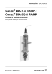
Conex
1
Man
Cal
OK
TM03 5850 1106
Esc
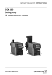
Fig. 1
AQC-D1 potentiostatic measuring cell with
Conex® DIA / DIS measuring amplifier
TM03 5851 1106
2
Fig. 2
AQC-D1 potentiostatic measuring cell with sensor
interface
DIP
3
Select
Select
Man
Cal
OK
TM03 5852 1106
Esc
Fig. 3
AQC-D1 potentiostatic measuring cell with DIP
measuring amplifier
1
Conex DIA-1, Conex DIA-2, Conex DIA-2Q, Conex DIS-D
measuring amplifier
2
Sensor interface for Conex DIA-1, Conex DIA-2,
Conex DIA-2Q, cabinet-mounted device
3
DIP measuring amplifier
5
5. Identification
5.1 Nameplate, AquaCell
TM03 8992 2807
Pos.
Fig. 4
Description
1
Type designation
2
Model
3
Serial number
4
Maximum pressure [bar]
5
Product number
6
Year and week code
7
Country of origin
Nameplate, AquaCell
5.2 Type key, AquaCell
Type key example
AQC -D1, P AU-PCB-RCB, QS -T, G
Model
AQC
AquaCell
Application
D1
Pressure-proof, with cleaning motor (Cl2, ClO2, O3)
D2
Pressure-proof, with hydromechanical cleaning (Cl2, ClO2, O3)
D3
Pressureless, with hydromechanical cleaning (Cl2, ClO2, O3)
Pressure-loading valve
P
With pressure-loading valve
X
Without pressure-loading valve
Electrodes
AU
Gold
PT
Platinum
PCB
pH, ceramic diaphragm, with buffer solution
PCX
pH, ceramic diaphragm, without buffer solution
PTB
pH, PTFE diaphragm, with buffer solution
PTX
pH, PTFE diaphragm, without buffer solution
PKB
pH, KCl filling, with buffer solution
PKX
pH, KCl filling, without buffer solution
PGB
pH, gel filling, with buffer solution
PGX
pH, gel filling, without buffer solution
RCB
Redox, ceramic diaphragm, with buffer solution
RCX
Redox, ceramic diaphragm, without buffer solution
RTB
Redox, PTFE diaphragm, with buffer solution
RTX
Redox, PTFE diaphragm, without buffer solution
RRB
Redox, without reference system, with buffer solution
RRX
Redox, without reference system, without buffer solution
X
No electrode
Flow sensor
QS
Flow sensor
X
No flow sensor
Temperature sensor
T
With Pt100
Power supply
G
1 x 230/240 V, 50/60 Hz
H
1 x 115/120 V, 50/60 Hz
I
24 VDC
X
No power supply
6
5.3 Type key, preassembled system
Example:
DIA
-1
-A
D1
P -AU -PCB -QS -T W -G
Units for measurement and control
DIA-1
DIA-2
DIA-2Q
DIP
DIS-PR
DIS-D
Dosing
Dosing
Dosing
Dosing
Dosing
Dosing
Instrumentation
Instrumentation
Instrumentation
Instrumentation
Instrumentation
Instrumentation
Advanced with 1 input
Advanced with 2 inputs
Advanced with 1 input + flow measurement
Pool
Standard for pH/redox measurement
Standard for Cl2 / ClO2 / O3
Assembly
A
Preassembled
Cell type
D1
D2
D3
D4
D5
P/R
F
PA/HP
Pressure-proof, with cleaning motor
Pressure-proof, with hydromechanical cleaning
Pressureless, with hydromechanical cleaning
Pressureless, with cleaning motor, for total chlorine
Pressureless, with cleaning motor, for free chlorine
pH or redox only
Fluoride only
Peracetic acid or hydrogen peroxide only
Pressure-loading valve
P
X
With pressure-loading valve
Without pressure-loading valve
Electrodes for disinfection
AU
PT
X
Gold
Platinum
No disinfection measurement
Other electrodes
PCB
PCX
PTB
PTX
PKB
PKX
PGB
PGX
RCB
RCX
RTB
RTX
RRB
RRX
F
PA
HP
X
pH, ceramic diaphragm, with buffer solution
pH, ceramic diaphragm, without buffer solution
pH, PTFE diaphragm, with buffer solution
pH, PTFE diaphragm, without buffer solution
pH, KCl filling, with buffer solution
pH, KCl filling, without buffer solution
pH, gel filling, with buffer solution
pH, gel filling, without buffer solution
Redox, ceramic diaphragm, with buffer solution
Redox, ceramic diaphragm, without buffer solution
Redox, PTFE diaphragm, with buffer solution
Redox, PTFE diaphragm, without buffer solution
Redox, without reference system, with buffer solution
Redox, without reference system, without buffer solution
Fluoride
Peracetic acid
Hydrogen peroxide
No electrode
Flow sensor
QS
X
Flow sensor integrated
No flow sensor
Temperature sensor
T
X
With Pt100
No temperature sensor
Mounting
W
P
Wall-mounted
Panel-mounted
Power supply
G
H
I
1 x 230 V, 50/60 Hz
1 x 120 V, 50/60 Hz
24 VDC
7
6. Unit description / holders for electrodes and sensors
Q1 Q2
Q2 Q1 A1/2 R R1 B1
F
V1
V1
M
O1
O
V2
N
L
K
L
K
E
U2
U1
I
J
U1
I
J
X
G1
G
A1/2
R
B1
V1
V2
TM03 5853 1106
Q P
O
L
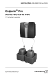
Fig. 5
Pos.
A
A1 / 2
8
AQC-D1 potentiostatic measuring cell (pressure-proof, with cleaning motor)
Component
Holders for pH single-rod electrode and redox
electrode (optional)
pH single-rod electrode and redox electrode (optional)
B
Holder for reference electrode
B1
Reference electrode (Cl2, ClO2, O3)
E
Plug for measuring electrode
F
Flow armature
G
Cleaning motor
G1
Slide
I
Calibration cup with sample water outlet
J
Evacuation spindle (on the calibration cup)
K
Sample water extraction device with extraction spindle
L
Bleeding spindle
M
Measuring tube
N
Float body
O
Water sensor (optional)
O1
Screw
P
E
Filter cartridge
Q
Sample water regulating device
Q1
Adjusting spindle
Q2
Valve insert
R
Screw plug
R1
Deaeration spindle
U1
Connection for sample water inlet
U2
Connection for sample water outlet
V1
Shut-off spindle for sample water inlet
V2
Shut-off spindle for sample water outlet
X
Cleaning wing
These positions that are described later on in the document are
not shown in the diagram:
Pos.
Component
D
Measuring electrode (Cl2, ClO2, O3) with integrated
Pt100
H
Screwed part with slide, inlet chamber, cleaning wing
and measuring electrode
P1
Filter for screw cap
P2
Filter strainer
P3
Filter receptacle
V
Pressure-loading valve, 0.3 bar, with adaptor
W
Inlet chamber
W1
O-rings of the inlet chamber
– Measurement: chlorine (Cl2), chlorine dioxide (ClO2), ozone
(O3).
7. General information
This manual contains all important information for users of the
AquaCell AQC-D1 and the preassembled systems:
•
technical data
•
instructions for start-up, use and maintenance
•
safety information.
Should you require further information, or should problems occur
which are not handled in sufficient depth in this manual, please
contact Grundfos Alldos. We will enjoy supporting you with our
comprehensive know-how in the fields of measurement and
control as well as water treatment.
– Control: chlorine (Cl2), chlorine dioxide (ClO2), ozone (O3).
•
Preassembled system with DIP measuring amplifier and
controller:
– Measurement: chlorine (Cl2), chlorine dioxide (ClO2), ozone
(O3), pH, redox potential, temperature.
– Control: chlorine (Cl2), chlorine dioxide (ClO2), ozone (O3),
pH.
9. Safety information
We always welcome any suggestions on how to optimise our
installation and operating instructions to satisfy our customers.
9.1 Obligations of the owner
7.1 Guarantee
•
compliance with country-specific safety regulations
A guarantee claim in the sense of our general conditions of sale
and delivery can only be recognised if these requirements are
complied with:
•
training of operating personnel
The owner of the plant is responsible for
•
provision of prescribed protective gear
•
implementation of regular maintenance.
•
The device has been used according to the information in this
manual.
•
The device has not been dismantled or incorrectly handled in
any manner.
Warning
•
Repairs have only been carried out by authorised personnel.
Do not dismantle the device components!
•
Only original parts have been used during repairs.
•
Only components approved by Grundfos Alldos are used in
the complete plant.
Cleaning, maintenance and repairs must only be
carried out by authorised personnel!
Typical parts subject to wear are excluded from the guarantee, for
instance a gaskets, magnetic stirrer, reference electrode and pH
redox single-rod electrodes.
8. Applications
The AQC-D1 potentiostatic measuring cell is used for measuring
the concentration of chlorine (Cl2) in the pH-range 4.5 to 8.5,
chlorine dioxide (ClO2) or ozone (O3). By means of the suitable
single-rod electrodes, it can also measure the pH value and redox
potential in plants for treating swimming-pool water and drinking
water.
9.2 Avoidance of danger
Warning
Other applications than those described in
section 8. Applications are considered as nonapproved and are not permissible. Grundfos
Alldos cannot be held liable for any damage
resulting from incorrect use.
Derivates of chlorine isocyanic acid cannot be
measured or controlled. Grundfos Alldos cannot
be held liable for damage or consequential
damage regarding this.
The preassembled systems measure and control the following,
depending on the measuring amplifier and controller installed:
•
Preassembled system with Conex® DIA-1 measuring amplifier
and controller:
– Measurement: free chlorine (Cl2), as an option with pH
compensation, chlorine dioxide (ClO2), ozone (O3), pH,
temperature.
– Control: chlorine (Cl2), chlorine dioxide (ClO2), ozone (O3).
•
Preassembled system with Conex® DIA-2 measuring amplifier
and controller:
– Measurement: free chlorine (Cl2), as an option with pH
compensation, chlorine dioxide (ClO2), ozone (O3), pH,
temperature.
– Control: chlorine (Cl2), chlorine dioxide (ClO2), ozone (O3),
pH.
•
Preassembled system with Conex® DIA-2Q measuring
amplifier and controller:
– Measurement: free chlorine (Cl2), as an option with pH
compensation, chlorine dioxide (ClO2), ozone (O3), pH,
temperature.
– Control: chlorine (Cl2), chlorine dioxide (ClO2), ozone (O3),
pH, redox potential.
•
Preassembled system with Conex® DIS-D measuring amplifier
and controller:
9
– water sensor with cable, 3 m
10. Technical data
– pressure-loading valve.
10.1 General data
•
AQC-D1: motor-driven pressure-proof flow armature for
recirculation of sample water.
•
Measuring parameters:
10.2.2 Preassembled systems
•
– cable for reference electrode, pH or redox single-rod
electrode, 1 m, preconnected
– free chlorine, chlorine dioxide, ozone
– optional: pH value, redox potential, temperature (for
compensation of pH, Cl2, ClO2, O3).
•
Sample water:
– min. conductivity: 50 µS/cm
– temperature: 0 to 50 °C
– pH value (only measuring parameter Cl2: pH 4.5-8.5)
– inlet pressure: max. 4 bar, min. 0.3 bar
– counter-pressure: max. 3.7 bar
Cables:
– cable for measuring electrode, 1 m, preconnected.
•
Options:
– water sensor with cable, 1 m
– pressure-loading valve.
Product numbers of the spare parts and optional accessories, see
section 16. Spare parts and accessories.
10.3 Measuring ranges
– pressure difference: max. 0.3 bar.
10.3.1 Measuring range for measuring parameters Cl2, ClO2,
O3, pH, Redox
•
Permissible ambient temperature: 0 to 40 °C.
Preassembled system with Conex DIA
•
Permissible storage temperature:
– –20 to +65 °C
– Electrodes: –10 to +30 °C.
Caution
•
Observe the installation and operating
instructions of the electrodes!
Permissible humidity: max. 90 % relative humidity (no
condensation).
Cl2
[mg/l]
ClO2
[mg/l]
O3
[mg/l]
pH
Redox
(ORP)
[mV]
0.00-0.50
0.00-0.50
0.00-0.50
0.00-14.00
–1500+1500
0-1000
0.00-1.00
0.00-1.00
0.00-1.00
2.00-12.00
0.00-2.00
0.00-2.00
0.00-2.00
5.00-9.00
0.00-5.00
•
Sample water flow rate: min. 20; max. 60 l/h.
•
Materials of parts that come into contact with the media:
PMMA, PVC, steel, PTFE, EPDM.
0.00-5.00
0.00-5.00
0.0-10.0
0.0-10.0
•
Electrode materials: Glass, metal, noble metal, PPO
(polyphenylene oxide), PA 6.6.
0.0-20.0
•
Connections:
– inlet: for PVC tube 6/12 or PVC pipe 12 x 1.2
freely selectable between
0.0-50.0
0.0-50.0
0.00-5.00
–1500+1500
0.00-14.00
– outlet: for PVC tube 6/12 or PVC pipe 12 x 1.2.
Cleaning motor
•
Cl2
[mg/l]
ClO2
[mg/l]
O3
[mg/l]
– 24 VDC.
0.00-2.00
0.00-2.00
0.00-2.00
Input power: 10 W.
0.00-20.00
0.00-20.00
0.00-5.00
– 230/240 V (50/60 Hz)
– 115-120 V (50/60 Hz)
•
Measuring parameters: chlorine, chlorine dioxide and ozone
•
Preassembled system with Conex DIS-D
Supply voltage:
Measuring ranges: Dependent on the measuring amplifier.
See section 10.3.1 Measuring range for measuring
parameters Cl2, ClO2, O3, pH, Redox.
Preassembled system with DIP
Cl2
[mg/l]
ClO2
[mg/l]
O3
[mg/l]
pH
Redox
(ORP)
[mV]
0.00-0.50
0.00-0.50
0.00-14.00
–1500+1500
0-1000
•
Sensitivity: < 10 ppb.
•
Accuracy: < ± 5 % of full-scale value.
•
Repeatability: < ± 3 %.
0.00-0.50
•
Response time: t90 < 60 s.
0.00-1.00
0.00-1.00
0.00-1.00
2.00-12.00
10.2 Versions
0.00-2.00
0.00-2.00
0.00-2.00
5.00-9.00
•
Power supply:
0.00-5.00
0.00-5.00
0.00-5.00
– 230/240 V (50/60 Hz) (standard)
0.0-10.0
0.0-50.0
– 115-120 V (50/60 Hz)
0.0-30.0
– 24 VDC.
•
Equipment / options:
– electrode (gold) (standard) (for free chlorine, chlorine
dioxide, ozone)
– electrode (platinum)
– redox single-rod electrode
freely selectable between
0.0-30.0
0.0-50.0
0.00-5.00
0.00-14.00
10.3.2 Measuring range for temperature (not with Conex
DIS-D)
– redox electrode (with DIP)
– pH single-rod electrode.
°C
°F
10.2.1 AquaCell AQC-D1 potentiostatic measuring cell
0 to +50
32 to 122
•
Cables:
0 to +100
32 to 212
– cable for reference electrode, pH or redox single-rod
electrode, 3 m, with free cable end
–5 to +120
23 to 248
– cable for measuring electrode, 3 m, with free cable end.
•
10
Options:
–1500+1500
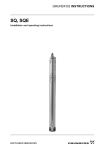
10.4 Dimensional sketches / drilling diagram
300
121
TM03 5854 1106
360
395
260
Fig. 6
Drilling diagram for AQC-D1 measuring cell
475
117
Conex
Man
Cal
OK
121
Fig. 7
TM03 5855 1106
495
475
Esc
Drilling diagram for preassembled systems. Example with Conex DIA (wall-mounted unit)
11
11. Installation
11.1 Transport and storage
Transport unit carefully, do not throw, store in
dry conditions between –20 and +65 °C.
Caution
Store electrodes between –10 and +30 °C. Keep
protective caps moist with 3-molar potassium
chloride solution.
11.2 Unpacking
Caution
Do not allow any foreign bodies to enter!
•
Check scope of delivery.
•
Assemble as soon as possible following unpacking.
11.4 Mounting
The flow armature is fastened to the mounting plate from factory.
Caution
The measuring cell breaks when the screws are
tightened! Do not tighten the screws; only screw
them in without tightening them!
Caution
The potentiostatic measuring cell or
preassembled system must be mounted
vertically!
Individual device for AQC-D1 measuring cells
1. Drill four dowel holes with a diameter of 10 mm and min.
60 mm deep. See section 10.4 Dimensional sketches / drilling
diagram.
2. Mount the measuring cell and the mounting plate on the wall
using the mounting material provided.
11.3 Installation requirements
TM03 5856 1106
Warning!
For safety reasons, the customer must install an
earth leakage circuit breaker for the cleaning
motor of the measuring cell and the measuring
amplifier.
Note
For safety during service and maintenance, the
measuring amplifier and the measuring cell must
be switched off at all poles.
To make the switching off easy, we suggest
installing an all-pole mains switch in front of the
measuring amplifier.
•
The location must be vibration-free, dry, dust-free and free of
corrosive, pungent fumes or aggressive solvents.
•
Maximum permissible cable length:
Fig. 8
Mounting of AQC-D1 measuring cell
Preassembled systems
1. Drill four dowel holes with a diameter of 10 mm and min.
60 mm deep. See section 10.4 Dimensional sketches / drilling
diagram.
2. Mount the preassembled system and the mounting plate on
the wall using the mounting material provided. Distance
between the mounting plate and the wall: min. 20 mm.
Caution
Do not pinch the cable! Always observe the
mounting sequence below.
– Individual devices for AQC-D1 measuring cells: between
measuring cell and measuring amplifier or sensor interface:
3 m.
– Preassembled systems with Conex DIS, DIA or DIP as wallmounted unit: completely prewired.
– Preassembled systems with Conex DIA as control cabinet
unit: Distance between measuring amplifier and sensor
interface ≤100 m.
•
Ensure a continuous supply of sample water.
•
Install the measuring cell so that the line length of the sample
water feed is as short as possible in order to reduce the delay
time of the flow armature.
•
Retain the permissible inlet pressure and counter-pressure of
the sample water.
– Fit a pressure booster pump or pressure reducer, if
necessary.
If the counter-pressure is under 0.3 bar, or if there is an open
outflow, fit the pressure-loading valve (V) to the outlet of the
measuring cell (U2). It is available together with an adaptor for
the measuring cell, Grundfos Alldos product number 96609179
(12.6459-400).
12
20 mm
Fig. 9
Mounting sequence for preassembled systems
TM03 5857 1106
Caution
Non-observance of the general installation
requirements may result in damage or errors in
measurement!
12. Start-up
12.1 Installation of electrodes and sensors
12.1.1 Reference electrode, pH and redox single-rod
electrodes
2. Remove the moisture retention caps of the electrodes or
single-rod electrodes (A1, A2, B1) used, and keep them for
possible electrode removal.
TM03 5860 1106
V
1. Unscrew the screw plugs of the holders (A, B) used for the
flow armature (F).
U2
3. Screw in the electrodes or single-rod electrodes (A1, A2, B1)
used by hand into the holders (A or B).
Caution
Fig. 12 Pressure-loading valve
Observe the installation and operating
instructions of the electrodes!
A
B
F
TM03 5858 1106
Caution
Warning
At a pressure of more than 4 bar and if the
measuring cell is not deaerated, the cell might
burst. Do not exceed the max. system pressure of
4 bar. Fit a pressure reducer, if necessary.
Fig. 10 Holders for electrodes
12.1.2 Water sensor
Note
Caution
The water sensor (O) is optional.
The holder for the water sensor is on the float
body.
1. Screw the water sensor (O) into the appropriate holder of the
measuring cell, and secure it using the screw.
2. Slacken the screw (O1), insert the water sensor as far as it will
go (O), and gently tighten the screw.
Observe the correct installation of the pressureloading valve. See the arrow on the pressureloading valve. The arrow must point in the flow
direction!
Observe the local pressure! The permissible
primary water pressure is 0.3 to 4 bar. Fit a
pressure booster pump, if necessary. Check the
tightness of the measuring cell.
4. Close the shut-off spindle for sample water inlet (V1) and
outlet (V2).
5. Connect the sample water inlet and outlet to the connections
of the sample water inlet (U1) and outlet (U2).
O
O1
TM03 5859 1106
F
V1
V2
Fig. 11 Holder for water sensor
12.1.3 Temperature sensor
The Pt100 temperature sensor is integrated into
the measuring electrode (D).
U1
12.2 Water connections
Caution
Only tighten the union nut by hand. Do not use
any tools!
For the pressure-proof measuring cell, a pressure-loading valve
must be fitted to the outlet of the flow armature if the counterpressure may fall below 0.3 bar (for instance if there is an open
outflow).
Product
number
96609179
(12.6459-400)
U2
TM03 5861 1106
Note
Fig. 13 Water connections
Component
Pressure-loading valve (V) with adaptor
12.2.1 Mounting the pressure-loading valve
1. Unscrew the connection of the sample water outlet (U2).
2. Screw the pressure-loading valve and adaptor (V) onto the
measuring cell outlet.
3. Screw the connection of the sample water outlet (U2) onto the
pressure-loading valve.
13
12.3 Floater stopper
The measuring cell is supplied with a built-in floater stopper. If the
sample water flow rate is increased, the float body (N) will
therefore not move outside of the detection range of the water
sensor (O). See the figure in section 12.3.1 Removing the floater
stopper. An alarm is not triggered, and the control output remains
active.
12.4 Preparing the electrode cable for connection to
the measuring amplifier
Note
The preassembled systems are prewired.
Warning
The electrical connection should be carried out
by qualified personnel!
The advantage of this is that in the event of frequent peaks in the
sample water flow rate, the alarm is not continuously triggered,
and the control output remains active.
Observe the local safety regulations!
Protect the cable connections and plugs against
corrosion and humidity.
Warning
If the sample water flow rate is set too high or is
increased temporarily, no alarm is triggered, and
the control output remains active!
Cables for single-rod electrodes or electrodes (A1, A2, B1)
If the sample water flow rate is set too high or is
increased temporarily, there is a risk that the
sample water will overflow at the overflow
mechanism. In this state, no alarm is triggered,
and the control output remains active!
2. Remove 80 mm of the outer insulation.
If the detection range of increased sample water flow rate is to be
activated, the floater stopper must be removed. When the floater
stopper is removed, an alarm is triggered, and the control output
is disabled each time the sample water flow rate is increased.
1. Cut the electrode cables to the desired length + approximately
80 mm for the connections.
3. Disentangle the braided screen until you reach the next part of
the insulation, and twist it to form a wire.
4. Strip the braided screen (for instance using a shrink tube), and
fit a wire end ferrule.
5. Remove the black (conductive) sheath of the insulated
electrode wire until you reach the insulation.
6. Fit a wire end ferrule to the electrode wire.
12.3.1 Removing the floater stopper
1. Close the water supply to the measuring cell.
TM03 5869 1106
TM03 5868 1106
70
TM03 5863 1106
TM03 5862 1106
10
Insulated
braided
screen
Fig. 17 Cable for single-rod electrode or electrodes (A1, A2,
B1)
Fig. 14 Floater stopper
2. Unscrew the adjusting spindle (Q1) from the valve (Q2).
Cable from measuring electrode (D)
1. Cut the electrode cables to the desired length + approximately
105 mm for the connections.
TM03 5865 1106
TM03 5864 1106
3. Unscrew the valve (Q2) from the fittings.
Fig. 15 Removing the floater stopper - part 1
6. Screw the adjusting spindle (Q1) into the valve (Q2).
7. Open the water supply to the measuring cell, and set the
desired water flow rate with the adjusting spindle (Q2).
14
TM03 5867 1106
TM03 5866 1106
5. Screw the valve (Q2) into the fittings.
3. Disentangle the braided screen until you reach the next part of
the insulation.
4. Cut the enclosed braided screen to 65 mm, isolate it (for
instance using a shrink tube), and fit a wire end ferrule. Then
remove the rest of the screen until you reach the insulation.
5. Cut the brown and white insulated wire of the measuring
electrode and counter-electrode to 65 mm, and fit wire end
ferrules.
4. Remove the floater stopper (C) from the fittings (for instance
using a pair of tweezers).
Fig. 16 Removing the floater stopper - part 2
2. Remove 105 mm of the outer insulation.
6. Fit wire end ferrules to the blue and black insulated wires of
the temperature sensor.
Caution
The temperature sensor cannot be used with
Conex DIS-D. Place the cables of the temperature
sensor so that no short-circuit can occur!
3. Connect the water sensor to the corresponding terminals of
the measuring amplifier.
4. Connect an earth leakage circuit breaker in front of the
measuring amplifier and the cleaning motor.
Insulated
braided screen
5. Connect the cleaning motor to the measuring amplifier in
accordance with local regulations.
Caution
Fig. 18 Cable from measuring electrode (D)
Pin
Measuring electrode M
Pin 2 white
Counter-electrode G/C
Pin 3 blue
Pt100 temperature sensor
Pin 4 black
Pt100 temperature sensor
1
2
5
3
4
6
7
12.5 Electrical connections
8
Warning
9
The electrical connection should be carried out
by qualified personnel!
Observe the local safety regulations!
1/
11
To make the switching off easy, we suggest
installing an all-pole mains switch in front of the
measuring amplifier.
2/ 2/
+3 - 4
1/
14
4/
3
4/
2
3/
1
4/
4
3/
3
3/
2
10
A
3/
4
1
B
4
Fig. 19 Conex DIA-1 for mounting in a control panel
15 17 19 21 23 25 27 29 31 33 35
37 38 39 40 41 42
16 18 20 22 24 26 28 30 32 34 36
1
4
5
1
2
4
3
6
7
10
8
9
TM03 5872 1106
Note
For safety during service and maintenance, the
measuring amplifier and the measuring cell must
be switched off at all poles.
4/
1
1/
13
1/
12
Protect the cable connections and plugs against
corrosion and humidity.
Connect an earth leakage circuit breaker in front
of the measuring amplifier and the cleaning
motor.
Conex
Sensor interface
Before connecting the supply cables, check that
the supply voltage specified on the type plate
corresponds to the local conditions!
Before connecting the supply cables, switch off
the electricity supply!
Pt 100
M B/R G/C
Component
Pin 1 brown
Before connecting the supply cables, check that
the supply voltage specified on the nameplate
corresponds to the local conditions! Observe the
installation and operating instructions of the
measuring amplifier!
Preassembled systems
The preassembled systems are prewired.
1. Connect an earth leakage circuit breaker in front of the
measuring amplifier and the cleaning motor.
2. Connect the electricity supply to the measuring amplifier.
Caution
TM03 5871 1106
105
65
TM03 5870 1106
6. Connect the electricity supply to the measuring amplifier.
Fig. 20 Conex DIA-1 for wall mounting
Observe the installation and operating
instructions of the measuring amplifier!
AQC-D1 measuring cell
Note
Caution
The cables are not preconnected. See section
12.4 Preparing the electrode cable for connection
to the measuring amplifier.
Observe the installation and operating
instructions of the measuring amplifier!
1. Connect electrodes to the corresponding terminals of the
measuring amplifier.
2. Connect measuring electrodes (D) to the corresponding
terminals of the measuring amplifier. Fit the screen according
to the installation and operating instructions of the measuring
instrument.
15
Pt 100
M B/R G/C
15 17 19 21 23 25 27 29 31 33 35
37 38 39 40 41 42
16 18 20 22 24 26 28 30 32 34 36
1
2
5
1
4
3
4
5
1
2
4
3
6
7
7
6
10
8
8
9
TM03 5876 1106
9
2/ 2/
+3 - 4
4/
1
1/
13
1/
12
1/
14
4/
3
4/
2
3/
1
4/
4
3/
3
3/
2
A
3/
4
1
B
10
4
Fig. 24 Conex DIA-2Q for wall mounting
Fig. 21 Conex DIA-2 for mounting in a control panel
20 21 22
14 16
15 17 19 21 23 25 27 29 31 33 35
37 38 39 40 41 42
16 18 20 22 24 26 28 30 32 34 36
1
4
19
1
4
5
1
2
5
1
2
4
3
6
7
10
6
7
10
8
9
8
Fig. 25 Conex DIS-D
TM03 5874 1106
9
53 55 57
1
Fig. 22 Conex DIA-2 for wall mounting
64 66
4
4
3
6
5
7
10
Pt 100
M B/R G/C
63 65
1
2
54 56 58
8
1
2
5
3
4
9
7
6
Fig. 26 DIP
8
Pos.
9
2/ 2/
+3 - 4
Sensor interface
1/
11
4/
1
1/
13
1/
12
1/
14
3/
1
4/
3
4/
2
4/
4
3/
3
3/
2
10
A
3/
4
1
B
4
TM03 5875 1106
Conex
Fig. 23 Conex DIA-2Q for mounting in a control panel
Component
1
Brown
2
White
3
Black
4
Blue
5
Screen
6
Outer conductor (screen)
7
Inner conductor
8
Reference electrode
Measuring electrode
9
Counter-electrode
10
Water sensor
Pt100 temperature sensor (not with Conex DIS-C)
12.6 Checks prior to start-up
•
•
16
Check the tightness of the whole system.
Check the electrical connections.
TM03 5878 1106
1/
11
TM03 5877 1106
Sensor interface
TM03 5873 1106
Conex
12.7 Switching on
Caution
Observe the installation and operating
instructions of the measuring amplifier and
device controlled!
Note
When carrying out a chlorine measurement with
pH compensation, the pH value must be
calibrated first, since the pH value is used when
calibrating the chlorine value!
Note
It is not necessary to remove the pH or redox
single-rod electrodes for calibration. Simply fill
the calibration cup (I) with the relevant buffer
solution.
Warning
At a pressure of more than 4 bar, and if the
measuring cell is not deaerated, the cell may
burst. Ensure draining and deaeration. Do not
exceed the max. system pressure of 4 bar. Do not
put a damaged measuring cell under pressure!
Caution
At first start-up or after a long-term stop: Let the
system run for at least two hours to avoid faulty
measurements and calibration!
1. Close the bleeding spindle (L) and the deaeration spindle
(R1).
2. Close the evacuation spindle (J).
3. Open the shut-off spindle for sample water outlet (V2) 23 turns.
4. Gradually open the shut-off spindle for sample water inlet (V2)
2-3 turns.
– Avoid turbulent flow!
5. Check that the cleaning wing (X) rotates.
– Try, if necessary, to briefly increase the quantity of sample
water with the adjusting spindle (Q1) in order to move the
cleaning wing (X).
– If the cleaning wing (X) still does not rotate, check and
correct its position, if necessary. See section
14. Maintenance.
6. Switch on the measuring amplifier.
7. Only switch on the device controlled after the first calibration,
if necessary.
Filling the calibration cup (I) with the relevant buffer solution
1. Close the shut-off spindle for sample water inlet (V1) and
outlet (V2).
2. Open the deaeration spindle (R1), open the evacuation
spindle (J), and drain the sample water through the slit in the
calibration cup (I).
3. Unscrew the calibration cup (I), and tighten the evacuation
spindle (J) again.
4. Fill the calibration cup (I) up to the mark with buffer solution,
and then loosely screw it back into the flow armature (F) by
hand.
This position ensures that the electrodes are immersed deeply
enough in the buffer solution.
Calibrating the pH value
•
•
1.
2.
3.
12.7.1 Setting the quantity of sample water
•
Set an average quantity of sample water with the adjustment
spindle (O1) so that the float body (N) is in the middle of the
measuring tube (M). (In order for the water sensor to work, the
float body must be at the height of the water sensor.)
12.8 Calibrating the parameters Cl2, ClO2, O3
Caution
At first start-up or after a long-term stop: Let the
system run for at least two hours to avoid faulty
measurements and calibration!
Due to the electro-chemical behaviour of the measuring cell, no
zero-point adjustment is necessary. Only the rate of rise
(sensitivity) must be adjusted during calibration.
Caution
•
During the calibration: Keep the pH value, sample
water flow rate and water temperature constant.
pH
cal. meas. value
cal result
cal cycle
5. Select one of the defined buffer solutions ("GRUNDFOS",
"DIN/NIST", the optional setting "others"), and press OK.
– The menu "temperature" is then selected automatically.
buffer
Check the calibration after 24 hours, and repeat, if necessary!
12.8.1 Photometrical measurement
1. Open the bleeding spindle (L), and let the water run for a few
seconds.
2. Take a water sample, and close the bleeding spindle (L).
3. Determine the concentration of the measuring parameter
photometrically, for instance using the Grundfos Alldos DIT
hand photometer.
Caution
Observe the installation and operating
instructions of the photometer!
12.8.2 Calibration example based on chlorine measurement
with pH compensation (not with Conex DIS-D)
Caution
•
4.
DIP: Select the right-hand display for pH with the Select
button.
Conex DIA and DIP: Use the CAL button to select the
calibration function CAL. The LED illuminates.
If necessary, enter the code number for Cal (or full)
authorisation.
Change to the menu "calibration" with the OK button.
Select the measured variable "pH", and confirm with OK.
– Selection possibilities: "cal. meas. value" (= measured
value), "cal result" and "cal cycle" (= count-down function
which triggers the alarm "Calibrate sensor" after a
selectable time interval of 1-100 days).
Select the line "cal. meas. value" with UP/DOWN.
Observe the installation and operating
instructions of the measuring amplifier!
GRUNDFOS
DIN/NIST
others
6. Enter the temperature of the buffer solutions.
7. Press OK to automatically jump to the menu "buffer value 1".
8. "GRUNDFOS" or "DIN/NIST" buffer solutions: Select one of
the three available buffer values.
buffer value 1
4.01 pH
7.00 pH
9.18 pH
If not done yet: Define the basic settings for the measuring
amplifier.
17
Buffer 1
1. Fill the calibration cup (I) up to the mark with buffer solution.
2. Screw the calibration cup (I) into the flow armature (F).
– Once the buffer values have been read by the measuring
amplifier, the temperature of the sample water and the
measured signal are automatically read.
3. Then discard the buffer solution.
– Unscrew the calibration cup (I).
– Do not return the buffer solution to the supply bottle!
– Flush the calibration cup (I) with water.
4. Press OK to automatically jump to the menu "buffer value 2".
Buffer 2
1.
2.
3.
4.
Select one of the two other buffer values.
Fill the calibration cup (I) up to the mark with buffer solution.
Screw the calibration cup (I) into the flow armature (F).
Press OK to automatically read the measured signal of buffer
value 2, and compare it with the buffer values.
– The calibration result is then displayed:
sensor gradient + asymmetry potential.
CALDATA pH
12.8.3 Calibrating the parameters chlorine, chlorine dioxide
or ozone with Conex DIS-D
1. Press the CAL selector, and select the calibration menu.
– The CAL LED next to the CAL selector illuminates.
– To prevent overdosing, the controllers must be switched off,
and the actuators closed.
– When the calibration function has been selected with the
CAL button, the measured-value display shows the current
measured value.
2. Use UP/DOWN to select the photometrically or analytically
determined reference value (for instance the value measured
photometrically using DIT).
3. Start the calibration with OK.
– The sensor data are then read in by an automatic read
function, and the calibration carried out.
– The gradient (sensitivity) of the sensor is calculated.
– The calibration result is displayed immediately after the
calibration.
– The sensor gradient is displayed in µA/ppm.
Calibration result
•
slope
- 60.17 mV / pH
asymmetry pot.
19 mV
5. Then discard the buffer solution.
– Unscrew the calibration cup (I).
– Do not return the buffer solution to the supply bottle!
– Flush the calibration cup (I) with water.
– Screw the calibration cup (I) into the flow armature (F).
6. Go back to the menu "calibration" with ESC.
Then calibrate the chlorine value!
Calibrating the parameters chlorine, chlorine dioxide and
ozone
•
DIP: Select the left-hand display for chlorine with the Select
button.
1. Select the calibration function with the CAL button. The LED
illuminates.
2. Press OK to select the menu "calibration".
3. Select "chlorine", and confirm with OK.
chlorine
cal. meas. value
cal result
cal cycle
4. Enter the reference value (for instance the value measured
photometrically using DIT).
– The measured signal is then read in automatically and
compared with the reference value.
– The calibration result is then displayed: sensor gradient.
CALDATA chlorine
slope
34.67 µA / ppm
Reading calibration data in the diagnostics menu "Service"
•
18
Select "Service" in the MAIN MENU with UP/DOWN, and
press OK (on both displays with DIP).
– The data of the last 10 calibrations can be read.
The result of the current (last) calibration can be displayed in
the code menu at any time:
– Code 51: display of calibrated gradient in µA/ppm.
Error message when reading in the current signal of the
sensor system
• The alarm LED flashes.
• The code flashes.
*13*: Gradient error.
The alarm is triggered if the plausibility check establishes an
upward or a downward violation of the following gradient ranges
depending on the selected measuring cell:
•
Measuring cell
Lower limit
Upper limit
AQC-D1
7.0 µA/ppm
70.0 µA/ppm
Press OK to acknowledge the error message and to return to
the display level.
– The calibration data are then imported.
Note
The instrument is operating in emergency mode!
Eliminate the fault, see section 13.5 Fault finding
chart, and calibrate again!
13.1 Function
Various oxidation agents are used for the disinfection of
swimming-pool water and drinking water, for instance chlorine
(Cl2), chlorine dioxide (ClO2) and ozone (O3).
It is necessary to measure the concentration of the oxidation
agent and to regulate its dosing for various reasons:
• The disinfection effect is too weak at too low concentrations.
• Too high concentrations have consequences:
– danger to health
– unpleasant odour and taste
– corrosion damage
– increased operating costs.
The AQC-D1 potentiostatic measuring cell is used for
measuring the concentration of chlorine (Cl2), chlorine dioxide
(ClO2) or ozone (O3) and is equipped with additional holders for
pH single-rod electrodes and redox single-rod electrodes, and
also for a water sensor and an integrated Pt100 temperature
sensor.
The preassembled system with Conex DIA, Conex DIS and DIP
are used when the values of decontamination agents, pH and
redox-potential have to be determined and controlled.
The basic element of the preassembled systems is the AQC-D1
potentiostatic measuring cell.
13.1.1 Functional principle of measurement
•
•
•
Sample water is taken at a representative position and passed
to the measuring cell via an integral filter.
– The water flow rate can be adjusted on the measuring cell.
– A water sensor (optional), for example, serves to trigger an
alarm or to switch off the control function if there is a sample
water deficiency.
– The agent to be determined (Cl2, ClO2 or O3) is measured at
the noble-metal electrode.
The material to be determined generates an electric current:
– in the µA range
– proportional to the concentration of the parameters Cl2,
ClO2 and O3.
– The measuring cell is controlled by a potentiostat integrated
into the measuring amplifier.
– A constant voltage is applied to the measuring electrode. An
exactly defined potential of the working electrode is retained
by means of the third electrode (reference electrode). This
results in a linear response for the measuring cell as well as
a stable zero point for the measurement.
The Conex or DIP measuring amplifiers and controllers
– amplify the current
– calculate it using the calibration parameters
– display the concentration as a digital value
– control a gas dosing unit or a dosing pump as the device
controlled.
13.1.3 Influence of temperature
The current generated on the electrodes depends on the
temperature of the sample water.
• The measured value increases by approx. 4 % per 1 °C
increase.
• Temperature variations can be compensated for by the
measuring amplifier if the temperature compensation function
is activated.
– The temperature can be measured using a Pt100
temperature sensor integrated into the measuring electrode.
– The temperature measuring signals are transferred to the
measuring amplifier and calculated using the electrode
signals.
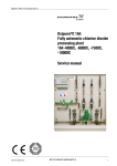
13.1.4 Influence of the pH value on the chlorine measurement
Free, active chlorine is considered as the total of molecular
chlorine gas (Cl2), hypochlorous acid (HOCl) and hypochlorite
anions (OCl-). Dissolved chlorine gas in molecular form
practically does not exist at the application-dependent pH values
(pH 4.5 to 8.5), but is subject to hydrolysis in the presence of
water according to the equation
Cl2 + H2O
HOCl + HCl
The resulting hypochlorous acid is the actually effective
compound for disinfection of the water. The dissociation of acid to
anions is primarily according to an equilibrium dependent on the
pH value according to the equation
HOCl + H2O
H 3O+ + OCl-
% OCl-
% HOCl
100
0
80
20
60
40
40
-
OCl
HOCl
20
60
80
0
4
5
6
7
8
9
pH
100
10 11
0 °C
10 °C
30 °C
TM03 5879 1106
13. Operation
Fig. 27 HOCl-OCl diagram
The potentiostatic measuring cell for chlorine primarily only
determines the portion of hypochlorous acid that is relevant for
disinfection.
Since the dependence on the pH value is particularly large in the
actually relevant range between pH 7 and pH 8.5, this
dependence must be compensated for in the measuring amplifier
if the pH value varies considerably. The pH value must therefore
also be measured, and the pH compensation function must be
activated on the measuring amplifier.
13.2 Operation
13.2.1 Switching on
13.1.2 Electrode cleaning
See section 12.7 Switching on.
The measuring electrode and the counter-electrode are
continuously cleaned of deposits by a cleaning wing which has a
gentle, yet effective action.
• This ensures uniform sensitivity for the measuring cell over a
long period.
• The cleaning motor drives a cleaning wing via a magnetic
clutch.
13.2.2 Operating state
Caution
•
Observe the installation and operating
instructions of the measuring amplifier and the
device controlled (for instance a gas dosing unit
or dosing pump)!
The operation of the measuring cell in the operating state can
be taken from the installation and operating instructions of the
relevant measuring amplifier.
Caution
The measuring cell may be damaged if the
reference electrode B1 is not connected, and the
electricity supply is switched on!
19
13.2.3 Adjusting / setting the quantity of sample water
•
Set an average quantity of sample water with the adjustment
spindle (O1) so that the float body (N) is in the middle of the
measuring tube (M).
When using a water sensor (O, optional): In order for the water
sensor (O) to work, the float body (N) must be at the height of
the water sensor (O).
•
Caution
Caution
Measuring cell with floater stopper (default upon
delivery): If the sample water flow rate is set too
high or is increased temporarily, no alarm is
triggered, and the control output remains active!
If the sample water flow rate is set too high or is
increased temporarily, there is a risk that the
sample water will overflow at the overflow
mechanism. In this state, no alarm is triggered,
and the control output remains active!
Measuring cell without floater stopper (see
section 12.3.1 Removing the floater stopper):
If the sample water flow rate is too high, the float
body (N) will move outside of the detection range
of the water sensor (O). In this state, an alarm is
triggered via the connected measuring amplifier,
and the control output is switched off, if
necessary. The flow rate is set correctly if the
float body (N) is at the height of the water sensor
(O).
11. Store electrodes with protective caps in a dry place. If they are
stored for an extended period of time, add a 3-molar
potassium chloride solution, if necessary.
12. Carefully unscrew the screwed part (H), and empty it of water,
if any.
Caution
13. Before starting up again, and if it is very dirty, clean the whole
flow armature (F). See section 14. Maintenance.
13.4 Switching on again
Caution
By increasing the sample water flow rate, the
delay time of the flow armature can be reduced.
13.3 Switching off
Caution
To avoid a dosing error, the device controlled (for
instance a gas dosing unit or dosing pump) must
be switched off each time the measuring system
is switched off. Observe the installation and
operating instructions of the measuring amplifier
and device controlled!
13.3.1 Short-term stop (up to one week)
1. Close and/or switch off the device controlled (for instance a
gas dosing unit or dosing pump).
2. Wait until the display of the measuring amplifier is at zero.
3. Switch off the measuring amplifier.
4. Close the connection to the sample water inlet (U1) and outlet
(U2).
Caution
To protect the electrodes, do not drain the water!
Make sure that the water level in the flow fitting F
is sufficiently high for the reference electrode B1
to be immersed at least 2 cm during device stop.
13.3.2 Long-term stop
1. Close and/or switch off the device controlled (for instance a
gas dosing unit or dosing pump).
2. Wait until the display of the measuring amplifier is at zero.
3. Switch off the electricity supply to the measuring amplifier and
the cleaning motor at all poles.
4. Close the connection to the sample water inlet (U1) and outlet
(U2).
5. Open the deaeration spindle (R1).
6. Open the bleeding spindle (L) and deaeration spindle (J), and
drain water.
7. Close the deaeration spindle again (R1).
8. Remove the reference electrode (B1), fit thread protective
caps, and clean the electrode.
9. Remove the pH (A1) and redox single-rod measuring chains
(A2), if necessary. Fit thread protective caps, and clean the
electrode.
10. Fit protective caps on the electrodes. The protective caps
must be filled with 3-molar potassium chloride solution.
Caution
20
Observe the installation and operating
instructions of the electrodes!
Observe the installation and operating
instructions of the measuring amplifier and
device controlled (for instance a gas dosing unit
or dosing pump)!
13.4.1 After short-term stop
Note
1.
2.
3.
4.
Fill the measuring cell with water.
Open the connection to the sample water outlet (U2).
Open the connection to the sample water inlet (U1).
Check the quantity of sample water.
Switch on the measuring amplifier.
Caution
Note
Carefully remove the screwed part (H)! The
cleaning wing (X) and inlet chamber (W) are loose
on the measuring electrode (D) and may fall out!
Let the system run for at least two hours to avoid
faulty measurements and calibrations!
5. Take a photometrical measurement.
6. Recalibrate, if necessary. See section 12.8 Calibrating the
parameters Cl2, ClO2, O3.
7. Switch on the device controlled (for instance a gas dosing unit
or dosing pump), if necessary.
13.4.2 After long-term stop / inspection
If the measuring cell has been switched off for a long period of
time or has been emptied, for instance for inspection, is it
necessary to start up the measuring cell as if it was the first startup. See section 12.6 Checks prior to start-up and 12.7 Switching
on.
13.5 Fault finding chart
Caution
Observe the installation and operating
instructions of the measuring amplifier and
controller!
Fault
Cause
Remedy
1. No display.
No electricity supply to
the measuring cell.
a) A disinfection or oxidation agent is missing in
sample water.
Check the concentration by making a reference
measurement. Check the dosing units, and
activate dosing. Check the settings of the
measuring amplifier.
b) The electrode cable connection is interrupted.
Remake the connection. Replace damaged
cables.
c) No or too low sample water flow rate.
Clean the filter, check the flow rate, and check
the sample water inlet pressure.
2. The measured value is
lower than the reference
measurement.
d) The measuring electrodes are faulty.
Replace the measuring electrode.
e) The measuring electrodes are contaminated or
made passive by deposits.
Dismantle, clean or replace the measuring
electrode.
a) The measuring electrodes are faulty.
Replace the measuring electrode.
b) The measuring electrodes are contaminated or
made passive by deposits.
Remove, clean or replace the measuring
electrode.
c) The temperature has fallen since the calibration.
Recalibrate. Activate the automatic temperature
compensation, where applicable.
d) The system has run too short time prior to
calibration.
Let the system run for at least two hours, and
recalibrate.
e) Unsuitable chlorination agent.
Only use chlorine solutions such as chloric gas,
sodium hypchlorite and chlorinated lime. Do not
use organic products such as trichlorine
isocyanic acid, as these cannot be measured if
this procedure is used.
f)
Check the reference measurement, and take
another measurement. Repeat the calibration.
Incorrect photometric reference measurement
during calibration.
g) The pH value for the chlorine measurement has
risen since the calibration.
Keep the pH value constant. Recalibrate.
Activate the pH value compensation.
h) The cleaning motor does not run.
Check the power voltage. Replace the cleaning
motor, if necessary.
i)
The quantity of sample water is set too low.
Check and set the quantity of sample water.
Check the filter, and clean it, if necessary.
j)
The cleaning wing is blocked.
Fit the cleaning wing correctly.
3. The measured value is
a) The temperature has risen since the calibration.
higher than the reference
measurement.
b) The pH value for the chlorine measurement has
fallen since the calibration.
4. The measured value is
unstable.
Recalibrate. Activate the automatic temperature
compensation.
Keep the pH value constant. Recalibrate.
Activate the pH value compensation, where
applicable.
c) Interference by other oxidation agents in the
sample water.
Analyse the sample water. Check the chemicals
used.
a) Interferences on the signal lines.
Check the screen and the connections to the
amplifier.
b) The reference electrode diaphragm is blocked.
Clean the diaphragm (on the side at the bottom
of the reference electrode) using diluted
hydrochloric acid (10 %). Replace the reference
electrode, if necessary.
c) The measuring electrode is contaminated or faulty. Clean the measuring electrode using a diluted
abrasive cleaning agent. Replace the measuring
electrode, if necessary.
d) The filter is contaminated, and the quantity of
sample water is therefore too low.
Check the filter, and clean it, if necessary.
21
14. Maintenance
14.1 Intervals for cleaning and maintenance
Warning
Prior to maintenance work: Switch off the system
as described in section 13.3 Switching off!
Make sure that the mains is switched at all poles!
•
Clean the filter
– if high contamination is evident, or if the pressure drops
considerably.
Clean the whole flow armature
– if high (visible) contamination is evident.
– if faults occur.
– before starting up again after a prolonged stoppage.
Replace the electrodes.
– Grundfos Alldos recommends that you replace the reference
electrode and, if necessary, the redox or pH single-rod
electrode after 12 months.
– The measuring electrode is wear-resistant and does not
have to be replaced on a regular basis.
•
•
Note
Required tools and aids:
– water
– soft brush.
Close the connection to the sample water inlet (U1) and outlet
(U2).
Unscrew the filter cartridge (P).
Unscrew the plastic screw thread (P1) at the upper end of the
filter cartridge (P), using a screwdriver or coin, if necessary.
Remove the filter strainer (P2) from the filter receptacle (P3),
and clean it under running water. Use a soft brush, if
necessary.
If damaged: Replace the filter strainer (P2).
Re-assemble the filter cartridge (P) in reverse order.
Check the tightness of the filter cartridge (P).
1.
2.
3.
4.
5.
6.
7.
Note
Caution
Observe the installation and operating
instructions of the electrodes!
– Store electrodes with protective caps in a dry place.
When cleaning the measuring electrode, do not
unscrew it from the cleaning motor!
14.2 Cleaning and replacing the filter
•
2. Empty the measuring cell.
– Open the deaeration spindle (R1).
– Open the bleeding spindle (L) and deaeration spindle (J),
and drain the water.
– Close the deaeration spindle again (R1).
– Unscrew the connections to the sample water inlet (U1) and
outlet (U2).
3. Remove the electrodes and sensors.
– If a water sensor is fitted: Unscrew the screw (O1) on the
water sensor (O), and remove the sensor.
– Unscrew the plug for the measuring electrode (E), and
remove the electrode.
– Remove the reference electrode (B1). Fit thread protective
caps, and clean the electrode.
– Remove the pH (A1) and redox electrodes (A2), if
necessary. Fit thread protective caps, and clean the
electrodes.
– Fit protective caps on the electrodes. The protective caps
must be filled with 3-molar potassium chloride solution.
After cleaning, check the sample water flow rate,
and adjust it, if necessary.
Note
Carefully remove the screwed part (H)! The
cleaning wing (X) and inlet chamber (W) are loose
on the measuring electrode (D) and may fall out!
Keep O-rings!
4. Unscrew the cleaning motor and measuring electrode.
– Unscrew the cleaning motor (G) and the screwed part (H)
from the flow armature (F) with the slide (G1), and remove
them carefully.
– Keep O-rings (W1).
– Remove the cleaning wing (X) and inlet chamber (W).
5. Remove the flow armature.
– Slacken the screws of the flow armature (do not unscrew
completely), press the flow armature upwards, and remove
it from the mounting plate.
W1
W
W1
X
H
G1
P1
G
P2
Fig. 29 Exploded view of screwed part
TM03 5880 1106
P3
Fig. 28 Filter
14.3 Cleaning the flow armature
14.3.1 Removing the measuring cell
Caution
The measuring cell must only be removed by
authorised personnel.
1. Close the water inlet, and switch off the measuring cell.
– Close the shut-off spindles of the sample water inlet (V1)
and outlet (V2).
– Close and/or switch off the device controlled (for instance a
gas dosing unit or dosing pump).
– Wait until the display of the measuring amplifier is at zero.
– Switch off the electricity supply to the measuring amplifier
and cleaning motor.
22
TM03 5881 1106
D
14.3.2 Dismantling the measuring cell
1. Remove the screw plug (R) and deaeration spindle (R1), and
separate them.
– Do not remove the plug from either of the two holes under
the screw plug!
2. Remove the sample water regulating device and float body.
– Remove the valve insert (Q2) and adjusting spindle (Q1),
and separate them.
– Remove the float body (N).
3. Remove the filter.
– Unscrew the filter cartridge (P).
– Slacken the screw cap for the filter (P1) at the upper end of
the filter cartridge (P).
– Remove the filter strainer (P2) from the filter receptacle
(P3).
4. Remove the calibration cup and evacuation spindle.
– Remove the calibration cup (I) and evacuation spindle (J),
and separate them.
5. Remove the shut-off spindles and the bleeding spindle.
– Unscrew the shut-off spindles of the sample water inlet (V1)
and outlet (V2) and the bleeding spindle (L).
W1
W
W1
14.3.3 Cleaning the measuring cell
X
G1
G
Fig. 30 Exploded view of screwed part / inlet chamber
P1
Observe the safety regulations when using
hydrochloric acid! When cleaning with
hydrochloric acid it is absolutely necessary to
wear safety goggles.
Before using other detergents, check the
chemical resistance of the materials, as they may
destroy some components.
Caution
Do not clean electrodes, filters, float bodies or
other metal parts using hydrochloric acid.
1. Clean the metal surfaces of the measuring electrode (D) and
the float body (N) with an abrasive domestic cleaning agent if
there are deposits.
2. Clean the filter strainer (P2) under running water. Use a soft
brush, if necessary.
3. Carefully clean all plastic parts with soap suds.
4. Use hydrochloric acid (5-10 %) for deposits.
5. Carefully rinse all parts with clean water.
6. Replace any damaged parts.
14.4 Assembling the measuring cell
Caution
Only tighten screw parts by hand; do not use
tools! Risk of leaking! Ensure that all O-rings are
fitted correctly!
1. Re-assemble the measuring cell in reverse order.
– Screw in the shut-off spindles of the sample water inlet (V1)
and outlet (V2) and the bleeding spindle (L).
– Assemble and screw in the calibration cup (I) and
evacuation spindle (J).
– Assemble and screw in the filter cartridge (P).
– Insert the float body (N) with the sharp end facing
downwards into the measuring tube (M).
– Tightly screw in the valve insert (Q2), and screw in the
adjusting spindle (Q1).
– Screw in the screw plug (R) and the deaeration spindle (R1)
(the plug under the screw plug must be inserted!).
2. Screw the flow armature onto the unit.
– Hook the flow armature (F) onto the screws of the mounting
plate, and pull it downwards. Screw in the screws of the flow
armature (F).
Caution
TM03 5882 1106
D
Warning
Caution
H
A1/2 B1
Q2 Q1 R R1
1
P2
2
P3
N
2
V1
O1
O
M
L
K
F
V2
2
6
U1
2
3
I
4
5
J
U2
W
X
H
D
G1
G
TM03 5883 1106
Required tools and aids:
– soap suds, possibly diluted hydrochloric acid (5-10 %),
water
– abrasive domestic cleaning agent (for instance ATA, VIM).
– The flow armature (F) can be cleaned with conventional
soap suds.
– If high contamination or furring is evident, clean the
dismantled flow armature (F) briefly with diluted hydrochloric
acid (max. 5-10 %).
TM03 5881 1106
•
Fig. 31 Exploded view of AQC-D1
15. Starting up the measuring cell
See section 12. Start-up.
The measuring cell breaks when the screws are
tightened! Do not tighten the screws; only screw
them in without tightening them.
3. Screw in the cleaning motor and measuring electrode.
– Fit the cleaning wing (X) and inlet chamber (W) with both
O-rings (W1) on the measuring electrode.
– Place the cleaning wing (X) with the larger surface area
downwards.
– Rotate the inlet chamber (W) until it engages with the
electrode in the defined position.
– Screw the cleaning motor (G) and the screwed part (H) with
the slide (G1) onto the flow armature (F).
23
16. Spare parts and accessories
16.1 Electrodes, sensors and cables
Product
number
Component
96609182
(321-252)
Cable for reference electrode, pH or redox
single-rod electrode, 1 m
96609183
(321-250)
Cable for reference electrode, pH or redox
single-rod electrode, 3 m
96609184
(321-140)
Cable for measuring electrode, 1 m
96609185
(321-141)
Cable for measuring electrode, 3 m
96609172
Water sensor with cable, 1 m
(45.10212-1)
96609173
(45.10212)
Water sensor with cable, 3 m
96609174
(314-605)
Reference electrode
96609175
(553-1561)
Measuring electrode, gold
96609176
(553-1562)
Measuring electrode, platinum
96609158
(312-100)
Single-rod measuring cell pH (standard)
96609162
(313-100)
Single-rod measuring cell redox (standard)
96622944
(313-105)
Redox electrode (in combination with DIP only)
96609181
(553-1564)
Cleaning wing
16.2 Other parts
Product
number
Component
Spare parts set
96609171
(553-1529)
Pos.
Designation
Quantity
1
O-ring 20 x 2
1
2
O-ring 10 x 2
4
3
O-ring 50 x 2
1
4
O-ring 45 x 3
1
5
O-ring 26 x 2
1
6
O-ring 8.3 x 2.4
1
96624812
(553-1593)
Screw plug with O-ring for holder A
(pH or redox single-rod measuring electrode)
91834713
(12.4568)
Filter strainer (P2)
96609179
Pressure-loading valve (V)
(12.6459-400)
17. Disposal
This product or parts of it must be disposed of in an
environmentally sound way:
1. Use appropriate waste collection services.
2. If this is not possible, contact the nearest Grundfos or
Grundfos Alldos company or service workshop.
Subject to alterations.
24
Argentina
Bombas GRUNDFOS de Argentina S.A.
Ruta Panamericana km. 37.500 Lote 34A
1619 - Garin
Pcia. de Buenos Aires
Phone: +54-3327 414 444
Telefax: +54-3327 411 111
Australia
Grundfos Alldos
Dosing & Disinfection
ALLDOS Oceania Pty. Ltd.
Unit 3 / 74 Murdoch Circuit
Acacia Ridge QLD 4100
Phone: +61 (0)7 3712 6888
Telefax: +61 (0)7 3272 5188
E-mail: [email protected]
Australia
GRUNDFOS Pumps Pty. Ltd.
P.O. Box 2040
Regency Park
South Australia 5942
Phone: +61-8-8461-4611
Telefax: +61-8-8340 0155
Austria
GRUNDFOS Pumpen Vertrieb Ges.m.b.H.
Grundfosstraße 2
A-5082 Grödig/Salzburg
Tel.: +43-6246-883-0
Telefax: +43-6246-883-30
Belgium
N.V. GRUNDFOS Bellux S.A.
Boomsesteenweg 81-83
B-2630 Aartselaar
Tél.: +32-3-870 7300
Télécopie: +32-3-870 7301
Belorussia
Представительство ГРУНДФОС в Минске
220090 Минск ул.Олешева 14
Телефон: (8632) 62-40-49
Факс: (8632) 62-40-49
Bosnia/Herzegovina
GRUNDFOS Sarajevo
Paromlinska br. 16,
BiH-71000 Sarajevo
Phone: +387 33 713290
Telefax: +387 33 231795
Brazil
Mark GRUNDFOS Ltda.
Av. Humberto de Alencar Castelo Branco,
630
CEP 09850 - 300
São Bernardo do Campo - SP
Phone: +55-11 4393 5533
Telefax: +55-11 4343 5015
Bulgaria
GRUNDFOS Pumpen Vertrieb
Representative Office - Bulgaria
Bulgaria, 1421 Sofia
Lozenetz District
105-107 Arsenalski blvd.
Phone: +359 2963 3820, 2963 5653
Telefax: +359 2963 1305
Canada
GRUNDFOS Canada Inc.
2941 Brighton Road
Oakville, Ontario
L6H 6C9
Phone: +1-905 829 9533
Telefax: +1-905 829 9512
China
Grundfos Alldos
Dosing & Disinfection
ALLDOS (Shanghai) Water Technology Co.
Ltd.
West Unit, 1 Floor, No. 2 Building (T 4-2)
278 Jinhu Road, Jin Qiao Export Processing
Zone
Pudong New Area
Shanghai, 201206
Phone: +86 21 5055 1012
Telefax: +86 21 5032 0596
E-mail: [email protected]
China
GRUNDFOS Pumps (Shanghai) Co. Ltd.
22 Floor, Xin Hua Lian Building
755-775 Huai Hai Rd, (M)
Shanghai 200020
PRC
Phone: +86-512-67 61 11 80
Telefax: +86-512-67 61 81 67
Croatia
GRUNDFOS predstavništvo Zagreb
Cebini 37, Buzin
HR-10010 Zagreb
Phone: +385 1 6595 400
Telefax: +385 1 6595 499
Czech Republic
GRUNDFOS s.r.o.
Čapkovského 21
779 00 Olomouc
Phone: +420-585-716 111
Telefax: +420-585-716 299
Denmark
GRUNDFOS DK A/S
Martin Bachs Vej 3
DK-8850 Bjerringbro
Tlf.: +45-87 50 50 50
Telefax: +45-87 50 51 51
E-mail: [email protected]
www.grundfos.com/DK
Estonia
GRUNDFOS Pumps Eesti OÜ
Peterburi tee 92G
11415 Tallinn
Tel: + 372 606 1690
Fax: + 372 606 1691
Latvia
SIA GRUNDFOS Pumps Latvia
Deglava biznesa centrs
Augusta Deglava ielā 60, LV-1035, Rīga,
Tālr.: + 371 714 9640, 7 149 641
Fakss: + 371 914 9646
Finland
OY GRUNDFOS Pumput AB
Mestarintie 11
FIN-01730 Vantaa
Phone: +358-3066 5650
Telefax: +358-3066 56550
Lithuania
GRUNDFOS Pumps UAB
Smolensko g. 6
LT-03201 Vilnius
Tel: + 370 52 395 430
Fax: + 370 52 395 431
France
Grundfos Alldos
Dosing & Disinfection
ALLDOS S.A.R.L.
7, rue Gutenberg
F-67610 La Wantzenau
Tél.: +33-3 88 59 26 26
Télécopie: +33-3 88 59 26 00
E-mail : [email protected]
Malaysia
GRUNDFOS Pumps Sdn. Bhd.
7 Jalan Peguam U1/25
Glenmarie Industrial Park
40150 Shah Alam
Selangor
Phone: +60-3-5569 2922
Telefax: +60-3-5569 2866
France
Pompes GRUNDFOS Distribution S.A.
Parc d’Activités de Chesnes
57, rue de Malacombe
F-38290 St. Quentin Fallavier (Lyon)
Tél.: +33-4 74 82 15 15
Télécopie: +33-4 74 94 10 51
Germany
Grundfos Alldos
Dosing & Disinfection
ALLDOS Eichler GmbH
Reetzstraße 85
D-76327 Pfinztal (Söllingen)
Tel.: +49 7240 61-0
Telefax: +49 7240 61-177
E-mail: [email protected]
Germany
GRUNDFOS GMBH
Schlüterstr. 33
D-40699 Erkrath
Tel.: +49-(0) 211 929 69-0
Telefax: +49-(0) 211 929 69-3799
E-mail: [email protected]
Service in Deutschland:
E-mail: [email protected]
Greece
GRUNDFOS Hellas A.E.B.E.
20th km. Athinon-Markopoulou Av.
P.O. Box 71
GR-19002 Peania
Phone: +0030-210-66 83 400
Telefax: +0030-210-66 46 273
Hong Kong
GRUNDFOS Pumps (Hong Kong) Ltd.
Unit 1, Ground floor
Siu Wai Industrial Centre
29-33 Wing Hong Street &
68 King Lam Street, Cheung Sha Wan
Kowloon
Phone: +852-27861706 / 27861741
Telefax: +852-27858664
Hungary
GRUNDFOS Hungária Kft.
Park u. 8
H-2045 Törökbálint,
Phone: +36-23 511 110
Telefax: +36-23 511 111
India
GRUNDFOS Pumps India Private Limited
118 Old Mahabalipuram Road
Thoraipakkam
Chennai 600 096
Phone: +91-44 2496 6800
Indonesia
PT GRUNDFOS Pompa
Jl. Rawa Sumur III, Blok III / CC-1
Kawasan Industri, Pulogadung
Jakarta 13930
Phone: +62-21-460 6909
Telefax: +62-21-460 6910 / 460 6901
Ireland
GRUNDFOS (Ireland) Ltd.
Unit A, Merrywell Business Park
Ballymount Road Lower
Dublin 12
Phone: +353-1-4089 800
Telefax: +353-1-4089 830
Italy
GRUNDFOS Pompe Italia S.r.l.
Via Gran Sasso 4
I-20060 Truccazzano (Milano)
Tel.: +39-02-95838112
Telefax: +39-02-95309290 / 95838461
Japan
GRUNDFOS Pumps K.K.
Gotanda Metalion Bldg. 5F,
5-21-15, Higashi-gotanda
Shiagawa-ku, Tokyo,
141-0022 Japan
Phone: +81 35 448 1391
Telefax: +81 35 448 9619
Korea
GRUNDFOS Pumps Korea Ltd.
6th Floor, Aju Building 679-5
Yeoksam-dong, Kangnam-ku, 135-916
Seoul, Korea
Phone: +82-2-5317 600
Telefax: +82-2-5633 725
México
Bombas GRUNDFOS de México S.A. de C.V.
Boulevard TLC No. 15
Parque Industrial Stiva Aeropuerto
Apodaca, N.L. 66600
Phone: +52-81-8144 4000
Telefax: +52-81-8144 4010
Netherlands
Grundfos Alldos
Dosing & Disinfection
ALLDOS BV
Leerlooiersstraat 6
NL-8601 WK Sneek
Tel.: +31-51 54 25 789
Telefax: +31-51 54 30 550
E-mail: [email protected]
Netherlands
GRUNDFOS Netherlands
Veluwezoom 35
1326 AE Almere
Postbus 22015
1302 CA ALMERE
Tel.: +31-88-478 6336
Telefax: +31-88-478 6332
e-mail: [email protected]
New Zealand
GRUNDFOS Pumps NZ Ltd.
17 Beatrice Tinsley Crescent
North Harbour Industrial Estate
Albany, Auckland
Phone: +64-9-415 3240
Telefax: +64-9-415 3250
Norway
GRUNDFOS Pumper A/S
Strømsveien 344
Postboks 235, Leirdal
N-1011 Oslo
Tlf.: +47-22 90 47 00
Telefax: +47-22 32 21 50
Poland
GRUNDFOS Pompy Sp. z o.o.
ul. Klonowa 23
Baranowo k. Poznania
PL-62-081 Przeźmierowo
Tel: (+48-61) 650 13 00
Fax: (+48-61) 650 13 50
Portugal
Bombas GRUNDFOS Portugal, S.A.
Rua Calvet de Magalhães, 241
Apartado 1079
P-2770-153 Paço de Arcos
Tel.: +351-21-440 76 00
Telefax: +351-21-440 76 90
România
GRUNDFOS Pompe România SRL
Bd. Biruintei, nr 103
Pantelimon county Ilfov
Phone: +40 21 200 4100
Telefax: +40 21 200 4101
E-mail: [email protected]
Russia
ООО Грундфос
Россия, 109544 Москва, ул. Школьная 39
Тел. (+7) 495 737 30 00, 564 88 00
Факс (+7) 495 737 75 36, 564 88 11
E-mail [email protected]
Serbia
GRUNDFOS Predstavništvo Beograd
Dr. Milutina Ivkovića 2a/29
YU-11000 Beograd
Phone: +381 11 26 47 877 / 11 26 47 496
Telefax: +381 11 26 48 340
Singapore
GRUNDFOS (Singapore) Pte. Ltd.
24 Tuas West Road
Jurong Town
Singapore 638381
Phone: +65-6865 1222
Telefax: +65-6861 8402
South Africa
Grundfos Alldos
Dosing & Disinfection
ALLDOS (Pty) LTD
98 Matroosberg Road, Waterkloof Park
P.O. Box 36505, Menlo Park 0102
0181 ZA Pretoria
E-mail: [email protected]
Spain
Bombas GRUNDFOS España S.A.
Camino de la Fuentecilla, s/n
E-28110 Algete (Madrid)
Tel.: +34-91-848 8800
Telefax: +34-91-628 0465
Sweden
GRUNDFOS AB
(Box 333) Lunnagårdsgatan 6
431 24 Mölndal
Tel.: +46(0)771-32 23 00
Telefax: +46(0)31-331 94 60
Switzerland
Grundfos Alldos
Dosing & Disinfection
ALLDOS International AG
Schönmattstraße 4
CH-4153 Reinach
Tel.: +41-61-717 5555
Telefax: +41-61-717 5500
E-mail: [email protected]
Switzerland
GRUNDFOS Pumpen AG
Bruggacherstrasse 10
CH-8117 Fällanden/ZH
Tel.: +41-1-806 8111
Telefax: +41-1-806 8115
Taiwan
GRUNDFOS Pumps (Taiwan) Ltd.
7 Floor, 219 Min-Chuan Road
Taichung, Taiwan, R.O.C.
Phone: +886-4-2305 0868
Telefax: +886-4-2305 0878
Thailand
GRUNDFOS (Thailand) Ltd.
92 Chaloem Phrakiat Rama 9 Road,
Dokmai, Pravej, Bangkok 10250
Phone: +66-2-725 8999
Telefax: +66-2-725 8998
Turkey
GRUNDFOS POMPA San. ve Tic. Ltd. Sti.
Gebze Organize Sanayi Bölgesi
Ihsan dede Caddesi,
2. yol 200. Sokak No. 204
41490 Gebze/ Kocaeli
Phone: +90 - 262-679 7979
Telefax: +90 - 262-679 7905
E-mail: [email protected]
Ukraine
ТОВ ГРУНДФОС УКРАЇНА
01010 Київ, Вул. Московська 8б,
Тел.:(+38 044) 390 40 50
Фах.: (+38 044) 390 40 59
E-mail: [email protected]
United Arab Emirates
GRUNDFOS Gulf Distribution
P.O. Box 16768
Jebel Ali Free Zone
Dubai
Phone: +971-4- 8815 166
Telefax: +971-4-8815 136
United Kingdom
Grundfos Alldos
Dosing & Disinfection
ALLDOS Ltd.
39 Gravelly Industrial Park, Tyburn Road
Birmingham B24 8TG
Phone: +44-121-3283336
Telefax: +44-121-3284332
E-mail: [email protected]
United Kingdom
GRUNDFOS Pumps Ltd.
Grovebury Road
Leighton Buzzard/Beds. LU7 8TL
Phone: +44-1525-850000
Telefax: +44-1525-850011
U.S.A.
GRUNDFOS Pumps Corporation
17100 West 118th Terrace
Olathe, Kansas 66061
Phone: +1-913-227-3400
Telefax: +1-913-227-3500
Usbekistan
Представительство ГРУНДФОС в
Ташкенте
700000 Ташкент ул.Усмана Носира 1-й
тупик 5
Телефон: (3712) 55-68-15
Факс: (3712) 53-36-35
Slovenia
GRUNDFOS PUMPEN VERTRIEB
Ges.m.b.H.,
Podružnica Ljubljana
Blatnica 1, SI-1236 Trzin
Phone: +386 01 568 0610
Telefax: +386 01 568 0619
E-mail: [email protected]
Addresses revised 22.10.2008
Being responsible is our foundation
Thinking ahead makes it possible
Innovation is the essence
15.730079 V9.0
Repl. 15.730079 V8.0
96681492 1108
Repl. 96681492 0908
GB
www.grundfosalldos.com
SECTION 9.3 PROCESS,
INSTRUMENTATION & CONTROLS
Section 9.3 Process, Instrumentation & Controls
9.3.14 Chlorine Analyzer-Grundfos
Model # Grundfos Conex DIA-2
Tag # AIT-316
Declaration of Conformity
We Grundfos Alldos declare under our sole responsibility that the product
Conex® DIA-2, to which this declaration relates, is in conformity with the Council
Directives on the approximation of the laws of the EC Member States relating to
– Electromagnetic compatibility (89/336/EEC).
Standards used:
EN 61000-3-2: 1995 + A1 + A2: 1998,
EN 61000-3-3: 1995,
EN 61326: 1997 + A1: 1998 + A2: 2001 Class B,
EN 61326: 1997 / A1: 1998 + A2: 2001.
– Electrical equipment designed for use within certain voltage limits
(73/23/EEC) [95].
Standard used: EN 61010-1: 2002.
Pfinztal, 15th April 2008
W. Schwald
Managing Director
2
Ulrich Stemick
Technical Director
CONTENTS
1.
2.
3.
4.
5.
6.
6.1
7.
8.
8.1
Symbols used in this document
A few words in advance
Installation data
Installation sketch
Instrument settings
General information
Warranty
Applications
Safety
Obligations of the owner/
operations manager
8.2 Avoidance of danger
9.
Identification
9.1 Nameplate
9.2 Type key, Conex® DIA-2 controllers
9.3 Type key, Conex® DIA-2 preassembled
systems
10. Technical data
10.1 Design / enclosure class
10.2 General data
10.3 Electronic data and functions
10.4 Measuring ranges
10.5 Dimensions
11. Installation
11.1 Transport and storage
11.2 Unpacking
11.3 Installation requirements
11.4 Installation in control panel
11.5 Installation of wall-mounted enclosure
12. Commissioning /
electrical connections
12.1 Terminals
12.2 Power supply connection
12.3 Relay outputs
12.4 Current output
12.5 Connections of controller stop,
sample-water sensor and temperature
sensor
12.6 Connection of measuring cells
13. Operation
13.1 Control and display elements
13.2 Display elements during initial
commissioning
13.3 Software overview
13.4 Main menu
13.5 Setup
13.6 Selection, configuration and
parameterisation of the controller
13.7 "Alarm" menu
13.8 Checking the settings in the
"service" menu
13.9 Calibration
13.10 Manual operation
14. Fault finding
15. Maintenance
16. Disposal
Page
3
4
4
5
6
8
8
8
8
8
8
9
9
10
11
12
12
12
12
13
14
15
15
15
15
15
16
Warning
These complete installation and
operating instructions are also
available on www.Grundfosalldos.com.
Prior to installation, read these
installation and operating instructions.
Installation and operation must comply
with local regulations and accepted
codes of good practice.
1. Symbols used in this document
Warning
If these safety instructions are not
observed, it may result in personal
injury!
Caution
Note
If these safety instructions are not
observed, it may result in malfunction
or damage to the equipment!
Notes or instructions that make the job
easier and ensure safe operation.
17
18
20
20
21
21
22
24
24
25
26
27
28
34
38
40
42
46
49
49
49
3
2. A few words in advance
The Conex® DIA-2 (Dosing Instrumentation
Advanced with 2 inputs) multipurpose measuring
amplifier and controller you have just purchased
uses the company’s leading-edge measuring
technology.
The Conex® DIA-2 is a multipurpose device
designed to carry out high-precision measurements
and controls of the following:
• a value from parameter group 1:
– chlorine, chlorine dioxide, ozone or hydrogen
peroxide
• a value from parameter group 2:
– pH value.
The integrated controller, the high-resolution
graphics display and the multilingual plain-text user
interface make complicated measuring and control
tasks in water chemistry much easier.
Just a few button inputs lead you to your goal. The
potentiostat helps save even more time, being
automatically matched to the various input variables.
The safety standard of the dosing process is raised
by the automatic open-circuit monitoring of the
current outputs.
Properties of the Conex® DIA-2 measuring amplifier
and controller include the following:
• all control functions including PID and
continuous-action controls
• setpoint control
• manual or automatic temperature compensation
• logbook function: chronological recording of
calibration values with date and time
• user coding function as a means of protection
against access by unauthorised persons and for
system administration
• error message function for indication of nonfunctioning sensors.
4
3. Installation data
Note
Please fill in the data below after
commissioning. It will help you and
your Grundfos Alldos service partner
make subsequent adjustments to the
installation.
Owner:
Grundfos Alldos customer number:
Order number:
Product number:
Product serial number:
Put into service on:
Location of product:
Used for:
4. Installation sketch
5
5. Instrument settings
Parameter 1
Setup
Controller
Alarm
Proportional Xp
Parameter
Controller
%
Chlorine:_
Chlorine dioxide:_
Ozone:_
Peroxide:_
Temp. meas.
Yes:_
No:_
Setpoint contrl.
Off:_
Limit:_
Interpulse ctrl.:_
Pulse freq. ctrl:_
Cont. controller:_
Limit contact
Downward viol.:_
Upward violation:_
Reset time TN
Alarm value 1
(PI/PID control)
Switching point
sec.
Deriv. action Tv
(PID control)
sec.
Temp. comp.
Ctrl. direction
Downward control:_
Upward control:_
Yes:_
No:_
pH compensation
Yes:_
No:_
Measuring ranges
Type of control
P:_
PI:_
PID:_
Int.pulse period
(interpulse ctrl.)
Alarm value 1
Switching direction
Upward violation:_
Downward viol.:_
Alarm value 2
Switching point
sec.
Min. ON time
Alarm value 2
(interpulse ctrl.)
sec.
Max. frequency
Switching direction
Upward violation:_
Downward viol.:_
Hysteresis
(pulse freq. ctrl)
mg/l (ppm)
Current output 1
Alarm
On:_
Off:_
n/min
Setpoint
Alarm delay
(limit contact)
mA
sec.
Constant load
Dos. time monit.
Measuring cell
%
Measuring cell type
Max. dosing flow
%
Cleaning motor
Monitoring on:_
Monitoring off:_
Water sensor
On:_
Off:_
6
Limit
(limit contact)
Hysteresis
(limit contact)
On:_
Off:_
Dos. time monit.
Max. dosing time
min
Parameter 2
Setup
Controller
Alarm
Proportional Xp
Parameter
Controller
%
Setpoint contrl.
Off:_
Limit:_
Interpulse ctrl:_
Pulse freq. ctrl:_
Cont. controller:_
pH
Temp. meas.
Yes:_
No:_
Limit contact
Downward viol.:_
Upward violation:_
Temp. comp.
Yes:_
No:_
Control direction
Downward control:_
Upward control:_
pH compensation
Yes:_
No:_
Measuring ranges
Type of control
P:_
PI:_
PID:_
Reset time TN
mA
Alarm value 1
(PI/PID control)
Switching point
sec.
Deriv. action TV
(PID control)
sec.
Int.pulse period
(interpulse ctrl.)
Alarm value 1
Switching direction
Upward violation:_
Downward viol.:_
Alarm value 2
Switching point
sec.
Min. ON time
Alarm value 2
(interpulse ctrl.)
sec.
Switching direction
Upward violation:_
Downward viol.:_
Max. frequency
Hysteresis
(pulse freq. ctrl)
mg/I (ppm)
Current output 1
Alarm
On:_
Off:_
n/min
Alarm delay
Setpoint
(limit contact)
sec.
Constant load
Dos. time monit.
%
Max. dosing flow
%
On:_
Off:_
Dos. time monit.
Max. dosing time
min
Limit
(limit contact)
Hysteresis
(limit contact)
7
6. General information
8. Safety
These installation and operating instructions contain
all information important for users of the
Conex ® DIA-2:
• technical data
• instructions on commissioning, use and
maintenance
• safety information.
Should you require further information or should you
encounter problems that are not handled in sufficient
depth in this manual, please contact Grundfos
Alldos. We shall be pleased to support you with our
comprehensive know-how in the fields of measuring
and control technology as well as water treatment.
We always welcome suggestions on how to optimise
our installation and operating instructions to satisfy
our customers.
The owner/operations manager must ensure that
persons working with the Conex® DIA-2 instrument
amplifier and controller fulfil these requirements:
• They are acquainted with the regulations
concerning working safety and accident
prevention.
• They have been trained in use of the device.
• They have read and understood the warning
information and handling symbols.
The owner/operations manager is also responsible
for ensuring that this manual is kept in the immediate
vicinity of the device and is always available for the
operating personnel.
6.1 Warranty
8.2 Avoidance of danger
8.1 Obligations of the owner/operations
manager
A warranty claim in accordance with our general
terms of sale and delivery is only valid if these
requirements are complied with:
• The device has been used in accordance with the
information in this manual.
The device has not been dismantled or handled
incorrectly.
Warning
Installation and connection of the
device and the associated
supplementary components must only
be carried out by authorised personnel!
The local safety regulations must be
observed!
7. Applications
Warning
Switch off the power supply before
connecting the power supply cable and
relay contacts!
Do not dismantle the device!
Maintenance and repair must only be
carried out by authorised personnel!
The Conex® DIA-2 instrument amplifier and
controller is suitable for measuring chlorine (Cl2),
chlorine dioxide (ClO2), ozone (O3), hydrogen
peroxide (H 2O2) and pH and for controlling these
variables using appropriate actuators within the
applications described in this manual.
Warning
Other applications are not approved
and not permitted. Grundfos Alldos
cannot be held liable for any damage
resulting from incorrect use.
8
Caution
The mounting location must be
selected so that the housing is not
subjected to mechanical loading.
Check that all settings are correct
before starting up the device!
9. Identification
9.1 Nameplate
2
3
4
5
11
6
DIA-2, 1-D/HP 2-P, W-G
354-2200-10001
S/N: 08/08565
Conex DIA-2
230/240V 50/60Hz, 15 VA,
IP 65
96622366P1108060808565
7
8
Fig. 1
Nameplate, Conex® DIA-2
Pos.
Description
1
12
10
9
TM04 0452 0708
1
Type designation
2
Model
3
Product name
4
Voltage [V]
5
Frequency [Hz]
6
Product number
7
Country of origin
8
Year and week of production
9
Marks of approval, CE mark, etc.
10
Power consumption [VA]
11
Enclosure class
12
Serial number
9
9.2 Type key, Conex® DIA-2 controllers
Type key example: DIA-2, 1-D/HP 2-P, W-G
Example:
DIA
Measuring amplifier and controller
DIA-2
Dosing Instrumentation Advanced with 2 inputs
Input parameter 1
D
Chlorine (Cl2), chlorine dioxide (ClO2) or ozone (O3)
HP
Hydrogen peroxide (H2O2)
Input parameter 2
P
pH
Mounting
W
Wall-mounted
P
Panel-mounted
Voltage
G
1 x 230 V, 50/60 Hz
H
1 x 120 V, 50/60 Hz
I
24 VDC
10
-2
1-D/HP
2-P
-W
-G
9.3 Type key, Conex® DIA-2 preassembled systems
Type key example: DIA-2-A, D1-P-PT-PCB-QS-T, W-G
Example:
DIA
-2
-A
D1
-P
-PT -PCB -QS
-T
W
-G
Units for measurement and control
DIA-2
Dosing Instrumentation Advanced, with 2 inputs
Assembly
A
Preassembled
Cell type
D1
D2
D3
D4
D5
P/R
P
X
Pressure-proof, with cleaning motor
Pressure-proof, with hydro-mechanical cleaning
Pressureless, with hydro-mechanical cleaning
For total chlorine measurement
For free chlorine measurement with buffer dosing
pH or redox (ORP) only
With pressure retention valve
Without pressure retention valve
Disinfection electrodes
AU
Gold
PT
Platinum
X
No disinfection measuring
Other electrodes
PCB
pH, ceramic diaphragm, incl. buffer solution
PTB
pH, PTFE diaphragm, incl. buffer solution
PKB
pH, KCl filling, incl. buffer solution
PGB
pH, gel filling incl. buffer solution
PCX
pH, ceramic diaphragm, excl. buffer solution
PTX
pH, PTFE diaphragm, excl. buffer solution
PKX
pH, KCL filling, excl. buffer solution
PGX
pH, gel filling, excl. buffer solution
X
No electrode
Flow sensor
QS
X
Flow sensor integrated
No flow sensor
Temperature sensor
T
X
With Pt100
No temperature sensor
Mounting
W
P
Wall-mounted
Panel-mounted
Voltage
G
H
I
1 x 230 V, 50/60 Hz
1 x 120 V, 50/60 Hz
24 VDC
11
10. Technical data
10.3 Electronic data and functions
10.1 Design / enclosure class
10.3.1 Electronics
Wall-mounted
enclosure
(distance from
sensors up to three
metres)
IP65
Control panel
enclosure
including separate
potentiostat
IP54 (front) /
IP65 (sensor interface)
(distance from sensor
interface up to 100 metres,
distance from sensor
interface to sensors up to
three metres)
Electronics
16-bit microprocessor
Display
High-resolution graphics LCD
with background light
Potential-free relay
outputs
1 alarm relay, 2 controller
relays (250 V/6 A, maximum
550 VA)
Signal inputs
Controller stop; water sensor
Signal outputs
10.2 General data
Input power
Approximately 15 VA
Permissible
ambient
temperature
0 °C to +50 °C
Permissible
storage
temperature
–20 °C to +65 °C
Maximum relative
humidity
90 % (non-condensing)
Weight
1.5 kg
Enclosure
Plastic (control panel
enclosure: noryl, wallmounted enclosure: ABS)
Power supply
versions
• 230/240 V (50/60 Hz)
(standard model)
• 115/120 V (50/60 Hz)
• 24 V DC
12
Freely adjustable
analog outputs for
measured values
4 analog outputs
0/4 to 20 mA, freely
adjustable, maximum load
500 Ω
• Parameter group 1:
chlorine, chlorine dioxide,
ozone or peroxide
• Parameter group 2: pH
• For temperature or
continuous control
(0/4 to 20 mA) of the
parameters from group
2 (pH)
• For continuous control
(0/4 to 20 mA) of the
parameters from group 1
(chlorine, chlorine dioxide,
ozone or peroxide)
10.3.2 Functions of the instrument amplifier
Display mode
Measured-value display:
measured value with its unit,
temperature display:
in °C or °F
Temperature
compensation
Manual or automatic with
Pt100 (–5 °C to +120 °C)
Calibration
Manual, or with automatic
recognition of buffer solution
10.3.3 Setpoint controller functions
Controller output
Limit monitor, interpulse
controller (P, PI, PID), pulse
frequency controller
(P, PI, PID), continuous
controller (P, PI, PID)
0 to 100 % of measuring
range, adjustable in the unit
of the measured value
(only with limit monitor)
Limit
0 to 50 % of full-scale value,
adjustable in the unit of the
measured value (only with
limit monitor)
Hysteresis
Setpoint input
0 to 100 % of measuring
range, adjustable in the unit
of the measured value
Proportional band
Xp
0.1 to 3000.0 %
Reset time Tn
1 to 3000 seconds, resolution
1 second (only with PI, PID
controllers)
Derivative action
time Tv
0 to 1000 seconds, resolution
one second (only with PID
controller)
Interpulse period
1 to 100 seconds (only with
interpulse controller)
Minimum ON time
Tmin
0.1 to 10.0 seconds (only with
interpulse controller)
Maximum
frequency
1 to 180 pulses per minute
(only with pulse frequency
controller)
Basic load
0 to 50 % of dosing rate
Maximum dosing
rate
Value (basic load + 1) to
100 % of dosing rate
Control direction
Adjustable to upward or
downward control
Controller stop
Adjustable to NC or NO
10.4 Measuring ranges
CI2
CIO2
O3
H2O2
pH
mg/l
mg/l
mg/l
mg/l
pH
0.00 - 0.50
0.00 - 0.50
0.00 - 0.50
0-100
0.00 - 14.00
0.00 - 1.00
0.00 - 1.00
0.00 - 1.00
0-500
2.00 - 12.00
0.00 - 2.00
0.00 - 2.00
0.00 - 2.00
0-1000
5.00 - 9.00
0.00 - 5.00
0.00 - 5.00
0.00 - 5.00
0-2000
0.00 - 10.00
0.00 - 10.00
0.00 - 20.00
Note
The measuring ranges are also freely adjustable (within the above-mentioned range limits).
In the case of chlorine and chlorine dioxide, the free adjustment of the measuring range can
be extended up to a maximum of 50.0 mg/l.
13
10.5 Dimensions
10
180
110
59
Ø 4.5
TM03 6687 4506
59.5
145
184.5
125
27
84
198
212
Wall-mounted enclosure Conex® DIA-2
90
96
Fig. 3
14
18
90
96
90
158
Control panel enclosure Conex® DIA-2
166
TM03 6688 4506
Fig. 2
11. Installation
11.4 Installation in control panel
11.1 Transport and storage
•
•
> 20
Transport the device carefully, do not drop!
Store at dry and cool location.
92+0.8
11.2 Unpacking
1. Check the device for damage.
Install as soon as possible after unpacking.
2. Do not install or connect damaged devices!
> 20
Retainthe packing material or dispose
of it according to local regulations.
TM03 6689 4506
Note
92+0.8
11.3 Installation requirements
Dry room
Room temperature: 0 °C to 50 °C
Vibration-free location.
Caution
Fig. 4
Control panel enclosure Conex® DIA-2
Fig. 5
Sensor interface
If you do not observe the installation
requirements, the device may be
damaged!
The measurements may not be correct!
TM03 6690 4506
•
•
•
1. Make an opening of 92 + 0.8 mm x 92 + 0.8 mm in
the control panel.
2. Slip on the supplied gasket.
3. Insert the Conex® DIA-2 into the opening from
the front.
Caution
Do not damage the gasket!
The gasket must be fitted exactly!
1. Hook the clamps into the tightening cones on the
sides at the top and bottom.
2. Secure the device from the rear using a
screwdriver.
3. Install a separate sensor interface near the
sensors (maximum distance of three metres).
15
Do not damage the terminal cover
gasket! The terminal cover gasket must
fit exactly!
10.5
Fig. 6
198
TM03 6691 4506
Caution
145
Warning
Switch off the power supply before
installing!
Enclosure class IP65 is only
guaranteed if the terminal cover is
correctly sealed, if the front panel of
the terminal enclosure is closed and
the appropriate cable glands or dummy
caps fitted.
27
11.5 Installation of wall-mounted enclosure
Wall-mounted enclosure Conex® DIA-2
1. Drill three holes (∅8 mm) as shown in the
diagram, and insert the supplied dowels.
2. Screw the screw (A) into the top centre dowel
until it projects by approximately 1 cm. See fig. 6.
3. Loosen the fastening screws of the front panel,
and remove the front panel.
4. Hang the instrument onto the screw (A).
5. Tighten the instrument with the two screws (B).
6. Mount the front panel of the enclosure.
A
B
Fig. 7
16
Mounting drawing
TM03 6692 4506
B
12. Commissioning / electrical connections
Warning
Switch off the power supply before
installing!
Enclosure class IP65 is only
guaranteed with the front panel of the
terminals enclosure closed and with
appropriate cable glands or dummy
caps.
Warning
Switch off the power supply before
connecting the power supply cable and
relay contacts! For safety reasons, the
protective conductor must be
connected correctly!
Observe the local safety regulations!
Protect the cable connections and
plugs from corrosion and moisture.
Caution
Before connecting the power supply
cable, check that the supply voltage
specified on the nameplate
corresponds to the local conditions!
An incorrect supply voltage may
destroy the device!
To guarantee electromagnetic
compatibility (EMC), the input and
current output cables must be
screened.
Connect the screening to the screen
ground on one side.
Refer to the wiring diagram! Route the
input, current output and power supply
cables in separate cable channels.
Caution
Enclosure class IP65 is only
guaranteed if the terminal cover is
correctly sealed! Do not damage the
gasket on the terminal cover!
The gasket on the terminal cover must
be positioned precisely!
Do not damage the gasket!
Note
Unused terminals must remain open.
1. Remove the terminal cover on the front of the
device.
2. Use the appropriate cable feedthroughs and
tighten the screws carefully.
3. Connect the cables used to the terminals
according to the Conex® DIA-2 terminal
assignment.
4. Close the terminal cover again with correctly
positioned gasket.
17
Terminals of wall-mounted enclosure
1
L N PE
3
5
2 4
+
6
-
1
3
2 4
5
7 9
6
8 10
12 14
N.O
.
L N PE
1
2
Relays
24
24 V/DC
V/DC
15 17 19 21 23 25 27 29 31 33 35
11 13
Alarm
N.C.
37 38 39 40 41 42
Cells / electrodes
16 18 20 22 24 26 28 30 32 34 36
15 (wh)
16 (br)
Cell
H 2 O2
17 - 22
Sensors
23 - 30
Outputs
mA
115/120
115/120V V
230/240
230/240VV
1
4
32,34,36
37 =
38 = M
39 = B/R
40 = G/C
41/42 = +/– pH
15 17 19 21 23 25 27 29 31 33 35
15 17 19 21 23 25 27 29 31 33 35
16 18 20 22 24 26 28 30 32 34 36
Sensors
21/22 = Pt 100
19 = + H2O, 20 = – H2O (water)
17/18 = Controller stop
16 18 20 22 24 26 28 30 32 34 36
Outputs
1
Cl 2 ,ClO 2 , O3 ,
H2O2
4
P1
pH P2
T / P2
P1
TM03 6977 4506
mA
1 +–
mA
2 +–
mA
mA
3 +–
4
+–
12.1 Terminals
Fig. 8
+
12.1.1 Wall-mounted enclosure Conex ® DIA-2
18
15 (white)
16 (brown)
Terminals of control panel enclosure
12.1.2 Control panel enclosure Conex® DIA-2
Fig. 9
1/11 (brown), 1/2 (white)
mA
Outputs
1
Cl2 , ClO2 ,
O3 , H2O2 ,
4
1/1 (br), 1/2 (wh)
H2O2
Cells:
1
5/1
5/2
pH
2
5/3
1/1
2/1
5/1
6/1
1/2
2/2
5/2
6/2
1/3
2/3
5/3
6/3
1/4
2/4
5/4
6/4
5/5
5/1 - 5/5
1/5
5/4
T
5/5
3/1
1/6
3
1/7
1/8
5/1 - 5/5
1/9
4
1/10
1/11
1/12
1/13
1/11 -1/14
Pt 100
M B/R G/C
+
pH
19
TM03 6978 4506
–
off
Pt 100
7/1
3/3
7/2
3/4
7/3
4/1
8/1
4/2
8/2
4/3
8/3
4/1 - 4/4
Cells
Cl 2, ClO 2,
O3,H2O2
DIP
Cells / electrodes
3/2
4/4
1/14
Sensor interface
on
2 /1, 2/2 = Controller stop
2/3 (+), 2/4 (–) = H2O (water)
1
Relays
2
N.O.
Alarm
N.C.
Conex DIA-2
Connection to
Conex® DIA-2
3/1 - 3/4
Electrodes
pH
Jumper
1/11 1/13 4/1 4/3 3/1 3/3
1/12 1/14 4/2 4/4 3/2 3/4
PE
N
L
115/120 VV
115/120
230/240 VV
230/240
–
1/1 (brown)
1/1
(br)
1/1 (wh)
(white)
1/2
H
2
O2
Cells
A
B
A
2 /3 (+)
B
2 /4 (-)
H2 O (water)
A
B
8/1
8/2
8/3
+
24
24V/DC
V/DC
Legend of terminals
Pos.
Description
Relays
Relay 1 + 2
Alarm
Alarm relay
– N.O.: normally open
– N.C.: normally closed
Pt100
Temperature sensor
H2O
Water sensor
Stop
Controller stop
(NO or NC selectable)
Outputs
Current outputs [mA]
1
Cl2 (chlorine), ClO2 (chlorine
dioxide), O3 (ozone) or H2O2
(hydrogen peroxide)
2
pH
3
T/P2: temperature / continuous
controller parameter 2
4
P1: output of continuous controller
parameter 1
Electrodes
Measuring cells, electrodes and
single-rod measuring chains
M
Measuring electrode
B/R
Reference electrode
G/C
Counter electrode
12.2 Power supply connection
1. Control panel enclosure: Plug the plug strip into
the corresponding terminal strip at the rear side of
the device. Ensure correct orientation.
2. Connect the protective earth conductor (PE) to
terminal 5 (wall-mounted enclosure) or terminal
8/1 (control panel enclosure).
3. Connect the neutral conductor (N) (or the conductor with 24 V version) to terminal 3 (wallmounted enclosure) or terminal 8/2 (control panel
enclosure).
4. Connect phase (L1) (or the + conductor with 24 V
version) to terminal 1 (wall-mounted enclosure) or
8/3 (control panel enclosure).
Switch the device on and off by switching the power
supply on and off accordingly. The device itself is not
equipped with a separate on/off switch.
12.3 Relay outputs
Note
The connection of the relay outputs
depends on the application and the
final control elements used. Therefore
the connections described below
should only be considered as
guidelines.
With inductive loads (also relays and contactors),
interference suppression is necessary. If this is not
possible, protect the relay contacts using a
suppressor circuit as described below.
• With AC voltage:
Earth
pH electrode
screen
Control panel enclosure Conex® DIA-2
• Conex® DIA-2: for installation in the control
panel.
• Sensor interface: for installation near the sensors.
•
Current up to
Capacitor C
Resistor R
60 mA
10 nF, 275 V
390 Ω, 2 W
70 mA
47 nF, 275 V
22 Ω, 2 W
150 mA
100 nF, 275 V
47 Ω, 2 W
1.0 A
220 nF, 275 V
47 Ω, 2 W
With DC voltage: Connect the free-wheeling
diode in parallel to relay or contactor.
Caution
Provide the relay outputs with a
corresponding backup fuse!
DC
AC
+
R
C
Fig. 10 Suppressor circuit, DC/AC
20
TM03 7209 4506
mV
12.4 Current output
Caution
Make sure that the polarity of the
current output is correct!
Maximum load: 500 Ω.
The current output can be set to one of the two
standard ranges "0-20 mA" or "4-20 mA", or it can be
freely adjusted.
• Connect the screen to earth (PE) at one end.
Output 1: chlorine, chlorine dioxide, ozone,
hydrogen peroxide (parameter 1)
This current output shows the displayed measured
value as an analog current signal.
Use of current signal for measured values:
• as input signal for another indicator
• as input signal for an external controller.
1. Connect the + conductor to terminal 23 (wallmounted enclosure) or terminal 1/3 (control panel
enclosure).
2. Connect the – conductor to terminal 24 (wallmounted enclosure) or terminal 1/4 (control panel
enclosure).
Output 2: pH (parameter 2)
This current output shows the displayed measured
value as an analog current signal.
Use of current signal for measured values:
• as input signal for another indicator
• as input signal for an external controller.
1. Connect the + conductor to terminal 25 (wallmounted enclosure) or terminal 1/5 (control panel
enclosure).
2. Connect the – conductor to terminal 26 (wallmounted enclosure) or terminal 1/4 (control panel
enclosure).
Output 3: continuous controller parameter 2
(or temperature)
Shows the calculated actuating variable signal of the
controller as an analog current signal.
Use of actuating variable signal:
• as input signal for a final control element with
current input
or temperature output:
Shows the temperature measured by the optional
temperature sensor as an analog current signal.
Use of temperature current signal:
• as input signal for another indicator.
1. Connect the + conductor to terminal 27 (wallmounted enclosure) or terminal 1/6 (control panel
enclosure).
2. Connect the – conductor to terminal 28 (wallmounted enclosure) or terminal 1/7 (control panel
enclosure).
Output 4: continuous control parameter 1
This current output shows the calculated actuating
variable signal as an analog current signal.
Use of actuating variable signal:
• as input signal for a continuous final control
element.
1. Connect the + conductor to terminal 29 (wallmounted enclosure) or terminal 1/8 (control panel
enclosure).
2. Connect the – conductor to terminal 30 (wallmounted enclosure) or terminal 1/7 (control panel
enclosure).
12.5 Connections of controller stop,
sample-water sensor and temperature
sensor
Connecting the controller stop
1. Connect the + conductor to terminal 17 (wallmounted enclosure) or terminal 2/1 (control panel
enclosure).
2. Connect the – conductor to terminal 18 (wallmounted enclosure) or terminal 2/2 (control panel
enclosure).
Connecting the sample-water sensor
Cable colours and marking: See connections of
measuring-cell types AQC-D1/AQC-D2/AQC-D3.
1. Connect the + conductor to terminal 19 (wallmounted enclosure) or terminal 2/3 (control panel
enclosure).
2. Connect the – conductor to terminal 20 (wallmounted enclosure) or terminal 2/4 (control panel
enclosure).
Note
When using measuring cell AQC-D2,
the water sensor must always be
connected and activated!
Connecting the Pt100 temperature sensor
1. Connect the + conductor to terminal 21 (wallmounted enclosure) or terminal 1/11 (control
panel enclosure).
2. Connect the – conductor to terminal 22 (wallmounted enclosure) or terminal 1/12 (control
panel enclosure).
21
12.6 Connection of measuring cells
37 38 39 40 41 42
1:
Standard
Fig. 11 Jumper setting
12.6.2 Connection of control panel enclosure
Conex ® DIA-2
M B/R G/C
6
37 38 39 40 41 42
16 18 20 22 24 26 28 30 32 34 36
1
4
Pt 100
3
4
7
15 17 19 21 23 25 27 29 31 33 35
TM03 6967 4506
Fig. 14 Connection to single-rod measuring
chains for pH, redox and fluoride
1
2
5
12.6.1 Connection of wall-mounted enclosure
Conex ® DIA-2
-
5
1
2
4
3
8
6
9
Conex
7
1/ 4/ 4/
3/ 3/
A
13 1
3
1
3
1/ 1/ 4/
4/ 3/ 3/
B
12 14 2
4
2
4
1/
11
TM03 5872 1106
9
15 17 19 21 23 25 27 29 31 33 35
37 38 39 40 41 42
10
4
B/R
G/C
1/11 1/13
4/1
4/3
1/12 1/14
4/2
12
11
3/1
4/4
A
3/3
3/2
1
16 18 20 22 24 26 28 30 32 34 36
3/4
2
B
1/1 1/2
+
12
2 1
Fig. 13 Connection to measuring cells HP
(peroxide)
TM03 6966 4506
11
1
Fig. 15 Connection to measuring cells
AQC-D1/AQC-D2/AQC-D3
M
Fig. 12 Connection to measuring cells AQC-D1/
AQC-D2/AQC-D3
22
2/ 2/
+3 - 4
Sensor
interface
Sensor-Interface
10
8
TM03 5871 1106
J
2:
+
7
13
Fig. 16 Connection to measuring cells HP
(peroxide)
TM03 6968 4506
2
1
Peroxide with AQC-D1/AQCD3
TM03 6696 4506
Jumper setting
• All measuring values except for peroxide:
All cell types: position 1 (standard).
• Measuring value peroxide:
Cell type HP (peroxide): position 1 (standard).
• Measuring value peroxide:
Cell types AQC-D1/AQC-D3: position 2 (move the
wire strap of the jumper (blue) to the higher
position).
Fig. 17 Connection to single-rod measuring
chains for pH, redox and fluoride
Pos.
Description
1
Brown
2
White
3
Black
4
Blue
5
Screen
6
Outer conductor (screen)
7
Inner conductor
8
Reference electrode
Measuring electrode
9
Counter electrode
Pt100 temperature sensor
10
Water sensor
11
Yellow
12
Green
13
Outer conductor
Peculiarities for the connection at the control
panel enclosure of Conex® DIA-2
1. First connect the measuring cells, the single-rod
measuring chains and the water sensor (if
present) to the separate sensor interface.
2. Secondly, connect the sensor interface to the
Conex® DIA-2 control panel enclosure.
Connecting the sensor interface to the
Conex® DIA-2 (see back side of device)
• Measuring cells AQC-D1/AQC-D2/AQC-D3/
HP (peroxide)
Connect terminals 4/1 to 4/14 of the sensor
interface to the corresponding terminals of the
Conex® DIA-2.
• Measuring cells HP (peroxide)
In addition, connect terminal A to terminal 1/1 and
terminal B to terminal 1/2 of the Conex® DIA-2.
• Single-rod measuring chains (pH)
Connect terminals 3/1 to 3/4 of the sensor
interface to the corresponding terminals of the
Conex® DIA-2.
• Sample-water deficiency sensor
Connect terminal A to terminal 2/3 and terminal B
to terminal 2/4 of the Conex® DIA-2.
Note
When using measuring cell AQC-D2,
the water sensor must always be
connected and activated!
DIP switch
• If necessary, set the DIP switch for the desired
measured value to "On" (move the switch to the
right, top switch 1 is not used).
OFF
DIP
1
2
3
4
On
ClO2, O3
H2O2
Cl2
TM03 6699 4506
7
13
TM03 6969 4506
+ -
Fig. 18 DIP switch
23
13. Operation
13.1 Control and display elements
6
1
5
4
3
2 7 8
Fig. 19 Wall-mounted enclosure and control panel enclosure
Pos. Description
Control elements
1
Red alarm LED
• Flashes in case of faults or incorrect
entries.
2
Display
Operating buttons
3
[OK] button
• Enters the selected menu.
• Confirms the selected line or value.
4
[Down] button
• Moves one line downward (the selected
line is displayed inversely).
• Decreases values.
5
[Up] button
• Moves one line upward (the selected line
is displayed inversely).
• Increases values.
6
[Esc] button
• Returns to the previous menu.
– The data which were entered last are
not changed.
Function buttons with yellow LED
24
7
[Cal] button
• Switches between calibration and
measuring mode.
– In calibration mode, the corresponding
LED illuminates.
8
[Man] button
• Switches between automatic and manual
modes.
– In manual mode, the corresponding
LED illuminates.
6 5 4
3
TM03 9528 4107
2 7 8 1
13.2 Display elements during initial
commissioning
chlorine
When connected to the power supply on the device’s
initial commissioning and following the start-up
indication, the display shows the "Sprache/language"
menu.
0.43 mg/l
Language/Langue...
•
English
Français
Nederlands
•
The word "language" in the header is displayed in
all available languages successively at intervals
of approximately one second.
Start the Conex® DIA-2 by selecting the desired
operating language:
1. Select the desired language using the [Up] and
[Down] buttons.
– The selected language is displayed inversely
(white letters on black background).
2. Press [OK] to confirm.
The translations for the words "setup" and
"language" into the currently available languages
are:
Deutsch
Hauptmenü
Sprache
setup
language
Paramétrage
Langue
basisinstelling
taal
Ajuste básico
Idioma
programm. fond.
lingua
Posição inicial
Língua
станд. настройка
язык
ustawienia
język
Nederlands
hoofdmenu
Español
Menu principal
Italiano
Menu principale
Português
Menu principal
Pусский
главное меню
5.20 pH
c
22 °C
c
•
On upward or downward violation of the selected
measuring range, the display will show the upper
or lower limit and flash.
See sections 10.4 Measuring ranges and
13.5.4 Setting the measuring ranges for chlorine,
chlorine dioxide, ozone, peroxide and pH.
13.2.1 Display modes
Switching between display modes 1 and 2:
1. Use the [Up] and [Down] buttons to switch
between the two display modes:
ClO2
Français
Menu principal
0.43 mg / l
Display mode 1 with two parameters
Grundeinstellung
English
main menu
chlorine
0.30
4.00
pH
mg/l
pH
TM03 6971 4506
Note
The selected language is stored and
will remain the operating language
when the device is rebooted. If
necessary, the operating language can
be changed in the "language" submenu
in the "setup" menu.
See section 13.5 Setup.
After selecting and confirming the operating
language by pressing [OK] during initial
commissioning, the display shows "chlorine" as
the value to be measured.
– On subsequent start-ups, the display will show
the measured value selected the previous time.
TM03 6704 4506
Deutsch
The large display shows the measured values for the
two parameters (for example ClO2 and pH). The
inverted font in the header displays the two
parameters left-justified and right-justified.
The measured value for the left-justified parameter 1
is displayed in the first line, and the measured value
for the right-justified parameter 2 is displayed in the
second line underneath the header. The measured
value for a possibly active temperature
measurement is not output in this display mode.
Polski
manu główne
25
Display mode 2 with two parameters
pH
4.00
100.0
mg/l
pH
c
°C
c
The large display shows the measured values for
parameter 1, and the small display shows the
measured values for parameter 2 and the possibly
active temperature measurement. "c" is displayed if
the compensation functions are active.
Display with one parameter
0.30
mg/l
alarm line 1
alarm line 2
The large display shows the measured values, and
the selected parameter is displayed in the header.
The measured value for a possibly active
temperature measurement and the display "c", if the
compensation functions are active, are suppressed.
13.3 Software overview
100.0
mg/l
°C
c
TM03 6973 4506
ClO2
0.30
The large display shows the measured values, and
the selected parameter is displayed in the header.
The measured value for a possibly active
temperature measurement is shown in the second
line. "c" is displayed if the compensation functions
are active.
Alarm signals
A parameter-based alarm refers to the flashing
parameter in the header. Parameter-independent
alarms are displayed in the bottom line, but the
display does not flash for this alarm.
If several alarms are present, they can be scrolled
using the [Up] and [Down] buttons. They are
displayed in chronological order. The selected alarm
signal is displayed with inverted font. Subsequently,
the display is switched to the last display mode set.
ClO2
pH
0.30
4.00
alarm line 1
alarm line 2
TM03 6974 4506
Display mode with active alarms and two
parameters
The parameters are displayed left-justified and rightjustified in the header, and the measured values of
the parameters are displayed directly underneath.
The measured value for a possibly active
temperature measurement and the display "c", if the
compensation functions are active, are suppressed.
26
TM03 6975 4506
0.30
ClO2
TM03 6972 4506
ClO2
Display mode with active alarms and one
parameter
Note
Provided that the code numbers for
access right have been set, some
menus (and submenus) as well as the
functions Cal and Man are protected
against unauthorised access. The
protected menus are marked with "C"
(calibration rights) or "F" (full rights).
Main menus
• Controller 1 / 2, see section Controller 1/2.
• Alarm 1 / 2, see section Alarm 1/2.
• Service, see section Service.
• Setup, see section Setup.
Function buttons
• Cal, see section Calibration function.
• Man, see section Manual operation.
Controller 1/2
"F" (full rights)
Setting the parameters
• Relay 1/2
– setpoint
– controller parameters.
• Continuous controller
– setpoint
– controller parameters.
Alarm 1/2
"F" (full rights)
• Alarm settings
– alarm 1/2 values (switching points)
– effective direction
– hysteresis
– alarm delay.
• Dosing time monitoring
– maximum dosing time (at constant dosing flow
level of 100 %).
Service
• Calibration logbook 1/2
– the last 10 calibrations.
• Calling up the controller 1/2 settings
• Test of functioning of current outputs
• Test of functioning of relays
• Test of functioning of display.
Setup
"F" (full rights)
• Selecting language
• Parameter 1/2: selecting measured values
• Selecting measuring cell
• Selecting measuring range
• Configuration of controller 1/2
• Switching on/off water sensor
• Time setting
• Code function
• Display contrast
• Calling up factory settings
• Current output: assignment of current outputs to
measuring ranges
• Calling up program version.
Calibration function
"C" (calibration rights)
• Calibration of selected parameters
– chlorine, chlorine dioxide, ozone, peroxide, pH.
Manual operation
"C" (calibration rights)
• Running the configured controllers manually.
13.4 Main menu
1. Switch to "main menu" by pressing [OK] or, if
necessary, by pressing [Esc] several times.
Options in "main menu"
main menu
controller
alarm
service
setup
•
•
•
•
"controller"
In this submenu, a controller can be
parameterised. This option will only be displayed
if a type of controller has been selected in the
"setup" menu.
"alarm"
In this submenu, the measured value is compared
with the permitted value, and an alarm is
triggered, if necessary.
"service"
Diagnosis submenu. The measured values and
the last 10 alterations of calibration data can be
viewed. In this mode, values cannot be altered.
If measuring cell AQC-D2 is selected, the data of
the water sensor can be viewed.
"setup"
In this submenu, the settings for language,
parameters, measuring ranges, controllers, etc.
can be adjusted.
Selecting the functions "calibration" and
"manual operation"
See the buttons [Cal] and [Man] to the right of the
display.
• Calibration: Press [Cal] to switch to the
calibration menu (the yellow LED illuminates).
• Manual operation: Press [Man] to switch to
manual operation (the yellow LED illuminates).
Note
Switching to manual operation is only
possible if a controller type has been
selected in the "setup" menu. The
functions "Cal" and "Man" can only be
accessed by persons with calibration
rights or full rights.
27
13.5 Setup
All standard settings of the device can be defined in
the "setup" menu. During initial commissioning, basic
functions are configured which after that should only
be altered rarely or even not at all.
The "setup" menu can only be accessed by persons
having full rights.
See section 13.5.8 Code function.
Enter the code number.
13.5.1 Selection of measured values for chlorine, chlorine dioxide, ozone, peroxide and pH
setup
parameter 1
off
chlorine
chlorine dioxide
ozone
peroxide
temp. meas.
on
off
parameter 2
pH-comp. chlorine *
on
off
temp. meas.
on
off
temp. meas.
on
off
TM03 6733 4506
off
pH
temp. comp.
on
off
Fig. 20 Selection of measured value in menus "parameter 1" and "parameter 2"
* pH-comp. chlorine is only available if chlorine and
pH have been selected as parameters.
1. Select the line "parameter 1" / "parameter 2"
using the [Up] and [Down] buttons, and press
[OK] to switch to the corresponding menu.
2. Use the [Up] and [Down] buttons to select the
measured variable (parameter). Press [OK] to
confirm.
3. Use the [Up] and [Down] buttons to select further
settings. Press [OK] to confirm.
28
13.5.2 pH and temperature compensation
13.5.3 Selection of measuring cell
pH compensation with chlorine measurement
The dissociation of hypochlorous acid (HOCl) into
the hypochlorit-anion (OCl–) leads to a loss of slope
(loss of sensitivity) of the sensor for chlorine
measuring.
Using a mathematical compensation function, this
loss of sensitivity can be eliminated.
Temperature compensation
Using a compensation function, the influence of
temperature on the measurement can be eliminated
mathematically.
Control field for pH value, pH compensation,
temperature and temperature compensation in
the display of measured value
c
c
TM03 6703 4506
0.43 mg/l
5.20 pH
Names of the measuring cells contained in the
software
• AQC-D1
• AQC-D2
• AQC-D3
• HP (peroxide).
The measuring cell that corresponds to the selected
measured value can be selected:
• AQC-D1/AQC-D2/AQC-D3 with chlorine, chlorine
dioxide or ozone
• AQC-D1/AQC-D3, HP with peroxide.
chlorine
22 °C
Note
The "measuring cell" submenu is
shown only if the measured values
chlorine, chlorine dioxide, ozone or
peroxide were selected during the
parameterisation.
Fig. 21 Chlorine measurement with pH and
temperature compensation
Measuring cell AQC-D2 / -D3 selected
chlorine
•
0.43 mg/l
TM03 6708 4506
Press [Esc] once or twice to change to the display
with the measured value.
See sections 13.2 Display elements during initial
commissioning and 13.6.3 Controller control fields
on the display.
In addition to the current measured value, the
current pH value and the temperature of the sample
water are indicated as well.
With activated pH compensation or temperature
compensation, the letter "c" for "compensation" is
displayed at the end of the line.
With deactivated temperature measurement, the
water temperature for compensation should be
entered manually after calibration. See section
13.9.2 Calibrating the pH value.
Monitoring the cleaning motor
(measuring cells AQC-D1)
Having selected measuring cell type AQC-D1, press
[OK] to get to the "cleaning motor" submenu.
1. Switch the monitoring of the cleaning motor
on/off.
Fig. 22 Chlorine measurement with AQC-D2 / D3
A black bar on the display indicates the actual data
of the water sensor.
See installation and operating instructions for the
potentiostatic measuring cell AQC-D2 / -D3.
29
Note
The "temperature" submenu is only
shown if the temperature measurement
has been switched on in the
"parameter" menu, or if parameter pH
has been selected.
13.5.5 Controller parameters 1/2
See section 13.6 Selection, configuration and
parameterisation of the controller.
13.5.6 Water sensor
In the "wat. def. sensor" menu, the water sensor can
be switched on/off.
In the event of sample-water deficiency, the following
will occur:
• The malfunction-indicating relay is activated, and
the alarm message "fault water sensor" is
triggered.
• With devices with control functions, the actuators
are switched to passive or closed.
Caution
The water sensor must be switched on
for the measuring cell AQC-D2!
13.5.7 Setting the current time
(date/time/summer time)
1. Switch from the "setup" menu to the "date/time"
menu.
time set
01 : 18 : 40 pm
time
TM03 6709 4506
13.5.4 Setting the measuring ranges for chlorine,
chlorine dioxide, ozone, peroxide and pH
In the "measuring ranges" menu, the corresponding
measuring ranges are assigned to the measured
values which have been selected in the "parameters"
menu.
• In the "measuring ranges" menu, the following
options are available:
– standard measuring ranges
– "others".
See section 10.4 Measuring ranges.
• The measuring ranges for temperature can be
defined in °C (Celsius) or in °F (Fahrenheit).
Fig. 23 Time setting
2. Set the device to the current time in the "time set"
menu in the format hh.mm.ss.
– Press [OK] to switch to the next number field.
The number field which is currently activated
flashes.
– Alter the settings by pressing the [Up] and
[Down] buttons.
– Pressing the buttons continuously makes the
adjustment dynamically faster.
3. Set the device to the current date in the "date"
menu in the format mm.dd.yyyy with English as
operating language or the format dd.mm.yyyy for
all other languages similarly to the adjustment of
time. The corresponding day of the week
(Mo...Su) is displayed automatically.
4. If necessary, enter the beginning and end date of
the summer time, the kind of time shift and the
number of hours of the time shift.
13.5.8 Code function
The code function is designed to protect the device
from unauthorised access.
Entering the four-digit code number and
changing it
1. Select the line "code function" in the "setup"
menu using the [Up] and [Down] buttons, and
press [OK] to switch to the corresponding menu.
There are two types of access rights:
Calibration rights: The owner of calibration rights
has access to the calibration menu and to manual
operation.
The owner of access rights may do the following:
• alter calibration data
• operate control relays manually.
30
Full rights: The owner of full rights has full access to
all settings including calibration data.
The owner of full rights may do the following:
• alter calibration data
• alter setup
• parameterise the controller
• alter alarm settings
• run the device manually.
cal right
code
13.5.9 Reset function
• Entering the code number "1998" deletes all
previously entered code numbers.
• All prior access codes are deleted and reset to
"0000".
13.5.10 Adjusting display contrast
In the "display" menu, the contrast of the display can
be adjusted.
1. Switch from the "setup" menu to the "display"
menu using the [Up] and [Down] buttons, and
press [OK] to confirm.
0000
Note
old code
2. Select the desired type of access rights, and
press [OK] to get to the corresponding menu.
3. If an old code exists, confirm the old code number
first (on first use, confirm code 0000).
4. Select "change".
5. Enter the old code in the submenu (see the
comment line at the bottom of the display) using
the [Up] and [Down] buttons, and press [OK] to
confirm and switch to the query "new code" (see
the comment line at the bottom of the display).
6. Enter a new four-digit code number using the [Up]
and [Down] buttons. Press [OK] to confirm.
7. Repeat to confirm: Set a new four-digit code
number using the [Up] and [Down] buttons, and
press [OK] to confirm.
8. Access rights can be cancelled by deleting the
corresponding code number in the "delete"
submenu.
• Entering a valid four-digit code number gives the
operator access to the corresponding functions
for a limited time of 60 minutes.
• If no code was entered previously, the desired
menu can be accessed without restrictions. The
code number 0000 will not be displayed / the
operator will not be asked to enter it.
Note
If the contrast setting is too high, it
may not be possible to read the
display. Hold down the [Down] button
until the contrast setting is low enough
to be read again.
13.5.11 Saving / accessing user settings
In the "factory setting" submenu, the current device
setting can be saved so that it can be reactivated
later, or a saved setting can be activated.
• Setup
- Save setup: Saves all current device settings
from the menus (not just the "setup" settings).
- Activate setup: Resets the device to the last
saved setup.
Note
In this menu, save your device settings
once you have set all the values in the
"setup", "controller" and "alarm"
menus. You can then activate them
again at any time (even after a factory
reset)!
If a wrong code is entered, access to
the corresponding menus is denied. An
error message is triggered
(duration: five seconds), and the device
will return to "main menu".
31
13.5.12 Factory setting reset
In the "factory setting" submenu, the Conex® DIA-2
can also be reset to the factory setting using code
6742.
Caution
Only use this function in an emergency.
All device settings are lost and must be
re-entered!
Do not disconnect the device from the
power supply during the reset!
Resetting the Conex® DIA-2 to the factory setting
• Reset
- Code: 0000 is displayed.
- Set code 6742 using the [Up] and [Down]
buttons, and press [OK] to confirm.
The device is now returned to the original factory
setting.
Caution
Before subsequent start-up:
Check all parameters and set the device
again according to your application!
General factory settings
• Language**: The Conex® DIA-2 is waiting for
language input. The languages "Deutsch/English
Français...." are indicated alternately.
• Summer time: off.
• Code numbers: 0000 calibration rights, 0000 full
rights.
• Current outputs 1-4: 0-20 mA.
• Dosing monitoring: off.
• Parameter 1: chlorine.
• Parameter 2: off.
** For the first calibration, the default value = last
setting.
Default values for parameter group 1
Cl2
ClO2/O3
H2O2
Measuring range [mg/l]
0.00 - 2.00
0.00 - 1.00
0-100
Measuring cell
AQC-D1
AQC-D1
AQC-D1
Temperature measurement
off
off
off
Water sensor
off
off
off
Default values for parameter group 2
pH
Measuring range
0.00 - 14.00
Temperature measurement
off
Water sensor
off
32
13.5.13 Current outputs
In the "current output" menu, the operator can assign
the selected values to the current outputs and then
assign the current outputs to the selected measuring
ranges.
In the "current output" menu, the selected
parameters are listed in the following order:
•
•
Enter the associated start-of-scale current value
using the [Up] button. Press [OK] to confirm.
– An additional line is displayed with the scan for
the full-scale value of the range "20.00 mg/l".
Enter the full-scale value of the range using the
[Down] button. Press [OK] to confirm.
– In the same line, "= 20 mA" is displayed.
current output
chlorine
chlorine
0.20 mg/l = 0 mA
pH
15.00 mg/l = 20 mA
temperature
•
•
•
•
Output 1: parameter group 1: chlorine, chlorine
dioxide, ozone, hydrogen and peroxide
Output 2: parameter group 2: pH
Output 3: temperature or continuous controller for
parameters from group 2
Output 4: continuous controller for parameters
from group 1.
Assignment of the current outputs to the
measuring range (example: chlorine
measurement)
There are two standard ranges, "0-20 mA" and
"4-20 mA" which can be assigned to the current
outputs. They are assigned to the measuring range
linearly.
The start-of-scale and full-scale values can be freely
defined within 0 to 20 mA in an optional setting for
the current outputs 1 and 2 as well as for current
output 3 with temperature measurements.
•
Enter the associated full-scale current value using
the [Down] button. Press [OK] to confirm and
return to the "current output" menu.
13.5.14 Program version
program version
Conex DIA-2
v0.20.1
20030304
In case problems make it necessary to contact our
service department, the "program version" menu
enables the operator to easily identify the software
components of the actual device.
• Version, for example v0.20.1.
• Last update: yyyymmdd.
chlorine
0-20 mA
4-20 mA
others
•
•
In the corresponding submenu (for example
chlorine), select the line "others" using the [Up]
and [Down] buttons. Press [OK] to confirm.
In the subsequent display "0.00 mg/l", enter the
start-of-scale value of the range using the [Up]
button. Press [OK] to confirm.
– In the same line, "= 0 mA" is displayed.
chlorine
0.20 mg/l = 0 mA
33
13.6 Selection, configuration and
parameterisation of the controller
It takes two steps to set up the controller:
• First: selection and configuration of the controller
type in the "setup" menu, "controller" submenu.
• Secondly: parameterisation of the selected
controller type in "main menu", "controller"
submenu.
13.6.1 Selection and configuration of the controller
setup
controller
parameter 1
setpoint contrl.
setpoint contrl.
off
limit contact
interpulse ctrl.
pulse freq. ctrl.
cont. controller
Limit contact
downward viol.
upward violation
ctrl. direction
downward control
upward control
ctrl. charact.
P
PI
PID
TM03 6734 4506
controller
parameter 2
parameter 2
as controller
parameter 1
Fig. 24 Selection and configuration of the controller
•
In the "setup" menu, select the line "controller
parameter 1" or "controller parameter 2" using the
[Up] and [Down] buttons, and select the menu
with the same name using [OK].
Selection and configuration of the setpoint
controller
1. Mark the "setpoint contrl" line using the [Up] and
[Down] buttons, and select using [OK].
34
2. Select the controller using the [Up] and [Down]
buttons as one of the following:
– off
– limit contact
– interpulse controller (two-position controller)
– pulse frequency controller (two-position
controller)
– continuous controller
and confirm using [OK].
If "limit contact" is selected:
3. Use the [Up] and [Down] buttons to select the
switching direction as one of the following:
– downward violation
– upward violation
and confirm using [OK].
If "interpulse ctrl.", "pulse freq. ctrl" or
"cont. controller" is selected:
4. Use the [Up] and [Down] buttons to select the
control direction as one of the following:
– downward control (switches with upward
violation of setpoint)
– upward control (switches with downward
violation of setpoint)
and confirm using [OK].
5. Use the [Up] and [Down] buttons to select the
control response as one of the following:
– P (proportional controller)
– PI (proportional-plus-integral controller)
– PID (proportional-plus-integral-plus-derivative
controller)
and confirm using [OK].
13.6.2 Setting the controller parameters
1. Select a controller in the "setup" menu and
configure it.
See section 13.5.5 Controller parameters 1/2.
2. Select the line "controller" in "main menu" using
the [Up] and [Down] buttons, and press [OK] to
switch to the "controller" menu.
See section 13.4 Main menu.
Note
The "controller" option in "main menu"
is only available if a controller has been
selected in the "setup" menu!
The options available in the "controller" submenu
(main menu) correspond to the configuration made in
the "setup" menu.
1. Use the [Up] and [Down] buttons to change
internal setpoints within the selected measuring
range.
See section 10.4 Measuring ranges.
2. Select the displayed controller parameters using
the [Up] and [Down] buttons, press [OK] to switch
to the desired submenu, and use the [Up] and
[Down] buttons to adjust the setpoints as needed
within the permitted ranges.
See section 10.3 Electronic data and functions.
main menu
controller
parameter 1/2
setpoint contrl
limit contact
setpoint contrl
interpulse ctrl.
setpoint contrl
pulse freq. contrl.
setpoint contrl
cont. controller
limit
hysteresis
stop
setpoint
prop. band xp
reset time TN **
deriv. action TV *
int. pulse period
Min. ON time
constant load
max. dosing flow
adaptation **
stop
setpoint
prop. band xp
reset time TN **
deriv. action TV *
max. frequency
constant load
max. dosing flow
adaptation **
stop
setpoint
prop. band xp
reset time TN **
deriv. action TV *
constant load
max. dosing flow
adaptation **
stop
* only with PID
** only with PI, PID
TM03 6735 4506
settings in the setup menu
Fig. 25 Settings for setpoint controllers
35
13.6.3 Controller control fields on the display
1. Press [Esc] once or twice to switch to the display
"measured value".
See sections 13.2 Display elements during initial
commissioning and 13.2.1 Display modes.
controller control fields
1
0.43 mg/l
1
5.20 pH
c
22 °C
c
continuous controller output
relay 1 or 2
control fields for pH or temperature
pH-meas. value,
temp. meas. value
"c" = compensation on
Fig. 26 Chlorine measurement with pH and temperature compensation
•
The control fields for relays 1 and 2 appear as
follows for configured limit monitors / two-position
controllers:
Unfilled field for relay off:
1
Filled field (displayed inversely) for relay on:
1
•
The control field for the continuous controller is
empty, partially filled or completely filled
depending on the set dosing rate - and when
configured accordingly - and the filling of the bar
always refers to 100 % of dosing rate.
Example:
0 %:
50 %:
100 %:
36
TM03 6736 4506
chlorine
13.6.4 Adaptation
An adaptation can be started to simplify the setting of
the controller parameters.
The adaptation is only available for PI and PID
controllers.
1. Start adaptation in the "controller" menu (main
menu) under "adaptation" by pressing "start".
The adaptation may be aborted in the following
cases:
• If an error message was shown during the
adaptation.
• If the controller is set to manual operation.
• If the standstill time was more than one hour.
• If the total measuring time was more than two
hours.
chlorine
0.43 mg/l
adaptation
TM03 6715 4506
Note
With selected temperature/pH
measurement, the temperature value,
pH value and their compensations will
not be displayed during the adaptation.
Fig. 27 Chlorine measurement with adaptation of
continuous controller
2. Return to the display "measured value"
automatically. A black bar on the display indicates
the adaptation process. The LED next to the
[Man] button flashes during the whole adaptation.
A progress bar shows the advancement of the
adaptation.
• The configured controllers can only be adapted
separately.
• On upward control, the measuring value has to be
more than 20 % below the setpoint.
• On downward control, the measuring value has to
be more than 20 % above the setpoint.
In case of a fault, the message "Start conditions
false" is shown directly after the start.
3. The message "adaptation successful" is shown
after ending the adaptation.
4. Press [OK] or [Esc] to quit. The determined
controller settings are automatically adapted by
the parameterisation of the controller. They are
displayed in the adaptation menu under
"adapt. result".
5. If the adaptation was not successful, the message
"adaption abortive" is shown. Press [OK] or [Esc]
to quit.
37
13.7 "Alarm" menu
With the help of the alarm function, the measured
value can be monitored and compared with the
permitted range.
If the measured value exceeds the limits of the
measuring range, an alarm is triggered.
• The alarm relay is activated after the selected
alarm delay time.
• When the cause of the alarm has been removed,
the relay is deactivated immediately (without
delay).
main menu
alarm 1
alarm value
alarm: off
alarm: on
alarm value 1
(switching point1)
downward
viol.
upward
violation
alarm value 2 as alarm 1
hysteresis
alarm delay
dos. time monit.
Fig. 28 "Alarm" menu in "main menu"
38
downward
viol.
upward
violation
TM03 6737 4506
alarm value 2
(switching point2)
alarm 2
1. Select the line "alarm" in "main menu" using the
[Up] and [Down] buttons.
2. Press [OK] to switch to the "alarm" menu.
Two functions are available there:
alarm values
0.00 mg/l
alarm
hysteresis
alarm values
dos. time monit.
•
•
alarm values: If the measured value exceeds the
permitted range, the alarm relay is activated and
an alarm message is triggered. The red alarm
LED starts flashing.
dos. time monit.: If the dosing flow constantly
remains at 100 % during a selected maximum
dosing time, the alarm relay is activated and an
alarm message is triggered. The red alarm LED
starts flashing.
Setting the alarm values
1. Select the line "alarm values" using the [Up] and
[Down] buttons. Press [OK] to switch to the "alarm
on/alarm off" submenu.
2. Confirm the line "alarm on" using [OK], and select
the "alarm values" selection menu.
Setting the upper and lower switching point
(limits)
1. Select the line "alarm value 1" or "alarm value 2".
Press [OK] to confirm and switch to the desired
menu.
7. Set the hysteresis to a value between 0 and half
of the measuring range using the [Up] and [Down]
buttons.
The hysteresis ensures that the relays switch less
frequently in the event of upward or downward
violation of the limits.
8. Press [OK] to return to the "alarm values" menu.
9. Select the line "alarm delay" in the "alarm values"
menu, and press [OK] in the corresponding
submenu.
alarm values
0 sec
alarm delay
10.Set the alarm delay to a value between 0 and 300
seconds using the [Up] and [Down] buttons.
13.7.1 Dosing time monitoring
This function can be used to monitor the dosing
process. If the dosing flow remains at a constant
level of 100 % during a selected period, an alarm
message is triggered.
alarm value 1
dos. time monit.
0.00 mg/l
10 min
switching point1
2. Set switching points between 0 and the upper
limit of the measuring range defined earlier using
the [Up] and [Down] buttons (in the unit of the
measured value, the resolution depends on the
selected measuring value and measuring range).
See section 10.4 Measuring ranges.
3. Press [OK] to switch to the "eff. direction" menu.
Options: alarm message in the event of upward/
downward violation of the selected switching point.
4. Select the desired line using the [Up] and [Down]
buttons.
5. Press [OK] to return to the "alarm values" menu
automatically.
6. Select the line "hysteresis" in the "alarm values"
menu, and press [OK] to switch to the
corresponding submenu.
max. dosing time
1. Select the line "dos. time monit." in the "alarm"
menu, and press [OK] to switch to the
corresponding submenu.
In the "dos. time monit." menu, the monitoring
function can be switched on or off.
• If "off" has been selected, the device returns to
the "alarm" menu.
• If "on" has been selected, the "dos. time
monit." submenu is displayed.
2. Set the maximum dosing time to a value between
0 and 600 minutes using the [Up] and [Down]
buttons.
39
13.8 Checking the settings in the "service"
menu
In the "service" menu, the operator can check all
important settings and test the functions of the
device in the event of problems that make service
necessary.
Note
In the "service" menu, calibration data
and controller settings cannot be
altered. Therefore the menu can be
accessed without an access code.
Select the line "service" in "main menu", and press
[OK] to switch to the corresponding menu.
main menu
service
CalData/
LogBook (5)
actual cell current in µA
actual measured value in mg/l
water sensor
(4)
calibration value in 1/min
actual measured value 1/min
controller parameters
controller 2 (3)
controller parameters
test relay
current outputs 1-4
relays 1/2 on/off
test display
Fig. 29 Example: chlorine measurement
40
cal no. (data set 1-10)
cal date
cal time
slope
cal temp (1)
cal pH (2)
measured value
controller 1 (3)
test current
-
values 0(4) mA / 10 mA /
20 mA on/off
TM03 6738 4506
chlorine
Notes to figures in fig. 29:
(1)
"cal temp." will only be displayed if
temperature measurement or temperature
compensation has been switched on in the
"setup" menu.
(2)
"cal pH" will only be displayed if pH
measurement or pH compensation has
been switched on in the "setup" menu.
(3)
"controller" will only be displayed if a
controller has been selected and
configured in the "setup" menu and in the
"main menu".
(4)
"water sensor" will only be displayed if
measuring cell AQC-D2 has been selected
in the "setup" menu.
(5)
"CalData/LogBook" will only be displayed if
a calibration has already been made.
service
chlorine
test current
test relay
In the "service" menu, the following items are listed:
• "parameter": displaying data of the previous 10
calibrations
• "controller": checking controller settings
• "test current": testing the functioning of the
current outputs
• "test relay": testing the functioning of the relays
• "test display": testing the functioning of the
display.
"parameter": logbook registration of calibration
data
The calibration data of all activated measuring
values are registered in chronological order by a
logbook function.
Example: With pH measurement, the logbook lists
the following data:
• calibration number with date/time
• slope (sensitivity of the electrode)
• asymmetric potential of the electrode
• temperature of the buffer solution used.
Under "measured value", the following data are
displayed:
• current measured value
• current cell voltage or cell current.
Under "water sensor", the following data are
displayed:
• speed of water sensor during last calibration
• actual speed of the water sensor.
"controller" (checking controller settings)
1. Select the [Up] or [Down] button depending on
the controller, and select the corresponding menu
using [OK].
– In the first line, the configured type of controller
is displayed, and in the subsequent lines the
current controller settings are listed. (Select the
value yout using [OK]).
"test current" (testing the functioning of the
current outputs)
1. Select the current output to be tested using the
[Up] and [Down] buttons, and press [OK] to switch
to the corresponding menu.
Depending on the configuration of the current
outputs, the current outputs can be switched on with
the following current values, and the current value
can be output to the system:
• test currents of 0, 10, 20 mA with selected
standard range 0-20 mA
• test currents of 4, 12, 20 mA with selected
standard range 4-20 mA or with freely adjusted
current outputs.
2. Select the current values using the [Up] and
[Down] buttons.
– When a line is selected, the state of the current
output with the corresponding value is
automatically set to "on".
– As soon as another line is selected, the
previous current value is automatically
switched off, and the new current value is set to
on.
"test relay" (testing the functioning of the relays)
1. Select the relay to be tested using the [Up] and
[Down] buttons, and press [OK] to switch it on or
off.
If either of the lines "relay 1", "relay 2" or "alarm" has
been selected, the relay that was the last one
activated before entering the test menu is switched
off. Considering the current alarm values and
controller values, the relay is switched on again
when the test menu is left.
"test display" (testing the functioning of
the display)
• If the display turns completely dark: The display
functions OK.
• If the display stays partly bright: The display is
faulty.
• Press [OK] to leave the test menu.
41
13.9 Calibration
1. Press [Cal] to switch to the calibration menu.
– The LED next to [Cal] illuminates.
2. Depending on the set access rights, it may be
necessary to enter the four-digit code number
using the [Up] and [Down] buttons. Confirm using
[OK].
3. Select a parameter for the calibration.
In order to avoid an overdosing, the controllers are
switched off, and the final control elements are
closed.
13.9.1 Peculiarities for the calibration of chlorine
with pH compensation
Caution
pH calibration is of prime importance,
since during the calibration of the
chlorine value, the device uses the
already calibrated measured value for
pH as a reference value.
Therefore the pH value must be
calibrated first!
Only then calibrate the chlorine value!
13.9.2 Calibrating the pH value
"Cal"
cal. meas.
value
GRUNDFOS
DIN /
NIST
temperature
of buffer
solution
others
manual
temp.
Fig. 30 Calibrating the pH value
42
automatic reading of
- measuring water
temperature
- measuring signal
and automatic
calibration
slope / asym. pot.
cal result
cal. cycle
buffer 1/2
on
1-100 days
cal result:
slope /
asym. pot.
TM03 6718 4506
pH
The pH calibration is carried out as a two-point
calibration.
pH
cal. meas. value
cal result
cal. cycle
1. Press [Cal] to switch to the calibration function.
Select the line "pH", and press [OK] to switch to
the "pH" calibration menu.
2. Select "cal. meas. value", and press [OK] to
switch to the corresponding menu.
Selecting buffer types and buffer values, reading
in buffer values and calibrating
Three optional buffer types are available:
• GRUNDFOS: buffer values pH 4.01, 7.00, 9.18.
• DIN/NIST: buffer values pH 4.01, 6.86, 9.18.
• "others": Lower and upper buffer values can be
freely adjusted (difference at least 1 pH) within
the configured pH value measuring range
("setup" menu).
buffer
GRUNDFOS
DIN/NIST
others
1. Select a buffer type using the [Up] and [Down]
buttons.
2. Press [OK] to jump to the "temperature" menu
automatically.
3. Enter the temperature of the buffer solution used.
4. Press [OK] to jump to the "buffer value 1" menu
automatically.
buffer value 1
4.01 pH
8. Press [OK] to start the automatic reading function
(reading in of measured signal) and the
calibration.
– The display shows the message "please wait"
during the calibration.
– The automatic reading function during pH
calibration has the effect that the correct
electrode signal for the buffer value is read in
only when the measuring signal remains stable
during a defined interval.
9. Dispose of the first buffer solution (i.e. do not
return it to the storage bottle!), and rinse the
electrode with water.
10.Press [OK] to jump to the "buffer value 2" menu
automatically.
buffer value 2
7.00 pH
9.18 pH
It is only possible to choose between the two
remaining buffer values.
1. Fill buffer solution 2 from the respective storage
bottle into a clean calibration cup.
2. Dip the electrode into the second buffer solution.
3. Press [OK] to start the automatic reading function
and the calibration.
4. After that, dispose of the buffer solution and rinse
the electrode with water.
CALDATA pH
slope
- 60.17 mV / pH
asym. pot.
19 mV
Immediately after the calibration, its result is
displayed automatically:
• sensor slope in mV/pH
• asymmetry potential of the electrode in mV.
7.00 pH
9.18 pH
5. Select one of the three optional buffer values
offered for the buffer solutions GRUNDFOS or
DIN/NIST.
6. Fill buffer 1 from the storage bottle into a clean
calibration cup.
7. Dip the electrode into the buffer solution.
43
Error messages during the reading in of the
voltage signal of the pH electrode
The calibration may be aborted in the following
cases:
• If the electrode is faulty or a wrong buffer has
been used.
– The message "fault of electrode/buffer" is
displayed.
• If the electrode does not reach a stable
measuring signal in 120 seconds.
– The message "calibration time exceeded" is
displayed.
• If the result of the plausibility testing of the pH
calibration data is upward/downward violation of
the slope range of –50 to –62 mV/pH.
– The message "slope error" is displayed.
• Downward/upward violation of the precision/
exactness range from –60 to +60 mV.
– The message "error asym. pot." is indicated.
The calibration process will be aborted in all four
cases.
• Press [OK] to return to the "calibration" menu
automatically.
If the process is aborted, the old calibration date will
not be overwritten!
Manual temperature compensation
With deactivated temperature measurement, the
water temperature for compensation should be
entered manually after calibration. The default value
is 25 °C.
1. Determine the water temperature with a
thermometer.
2. Press [Cal] to switch to the calibration function.
Select the line "pH", and press [OK] to switch to
the "pH" calibration menu.
3. Select "manual temp.", and press [OK] to switch
to the corresponding menu.
manual temp.
25 °C
4. Enter the water temperature.
– The water temperature is shown in °C (Celsius)
or in °F (Fahrenheit), as selected in the "setup"
menu "measuring ranges".
5. Press [OK] to return to the "calibration" menu
automatically.
44
Cal. cycle
• Following selection of "cal. cycle" in the
"measured value" menu, a countdown function is
started which triggers the alarm signal "calibrate
sensor" following expiry of a defined time interval
of 1-100 days.
Cal result
• The result of the current (last) calibration can be
displayed at any time using the "cal result" menu
item.
13.9.3 Calibration of the parameters chlorine, chlorine dioxide, peroxide and ozone
"Cal"
chlorine,
chlorine dioxide,
peroxide,
ozone
reference
value
cal. meas.
value
automatic reading of the
cell signal and calibration
slope
cal result
on
cal. cycle
0-100 days
TM03 6719 4506
cal result:
slope
Fig. 31 Calibration of the parameters chlorine, chlorine dioxide, peroxide and ozone
Having switched to the calibration function by
pressing [Cal], the display is in the mode "measured
value" and indicates the current measured value.
1. Press [OK] to switch to the calibration menu (the
first line reads "chlorine", for instance").
chlorine
cal. meas. value
cal result
cal. cycle
2. Select the line "cal. meas. value", and press [OK]
to switch to the corresponding menu.
•
In the bottom line, the entry field (value in mg/l)
for the reference value (determined
photometrically or analytically) and the present
cell current or electrode current (in µA) are
displayed.
3. Enter a reference value (for example determined
photometrically with the Grundfos Alldos DIT
photometer).
4. Press [OK] to start calibration.
– An automatic reading function reads in the
sensor data, and the calibration is carried out.
– The slope (sensitivity) of the sensor is
calculated.
• Immediately after calibration, the result of the
calibration is indicated automatically (first
line: "cal. meas. value"):
– The slope of the sensor in µA/ppm is displayed.
CALDATA chlorine
slope
34.67 µA / ppm
cal. meas. value
0.45 mg/l
I-cell 10.4 µA
45
13.10 Manual operation
The manual operation mode is used to switch off the
automatic control and run the control relays
manually.
Note
Manual operation is only possible after
a controller has been configured.
Manual operation can only be accessed
with calibration rights or full rights.
1. Press [Man].
3. The display reads "controller stop": All configured
controllers are switched off.
– With configured two-position and continuous
controllers, the actuating variable is set to 0.
– With configured-limit contacts, the
corresponding relay is switched off.
manual operation
controller
manual operation
active
controller
stop
2. Depending on the set access rights, it may be
necessary to enter the four-digit code number
using the [Up] and [Down] buttons.
– The LED next to [Man] illuminates.
4. Press [Man] to return to automatic operation.
– The LED next to the button goes out.
– The message "controller active" is shown on
the display for five seconds.
– After that, the device automatically returns to
the menu from which the manual operation was
started.
Note
Every time the manual-operation mode
is entered, every single controller type
must be activated again.
13.10.1 Manual operation with configured two-position and continuous controllers
controller
stop
manual
operation
relay 1
dosing flow
0-100 %
relay 2
dosing flow
0-100 %
Fig. 32 Manual operation with configured two-position and continuous controllers
46
TM03 6721 4506
"Man"
With configured two-position controllers, the relay
outputs 1 and 2 as well as the output
"cont. controller" can be separately run manually.
By selecting the desired relay output, the dosing flow
of the pump/pumps can be changed.
manual operation
3. Press [OK] to switch to the subsequent menu.
Three options are available:
• relay output 1
• relay output 2
• continuous controller.
manual operation
controller
relay output 1
stop
relay output 2
cont. controller
1. Having switched to manual operation, the
message "controller stop" is displayed for five
seconds.
– All controllers are switched off.
– The final control elements are closed (set to 0).
relay 1
1
5.20 pH
22 °C
c
c
TM03 6739 4506
manual operation
0.01 mg/l
4. Select relay output 1 using the [Up] and [Down]
buttons. Press [OK] to switch to the
corresponding menu.
5. Set the desired dosing rate of the pump using the
[Up] and [Down] buttons.
2. After that, the device automatically switches to
the mode "display measured value" (first
line: "manual operation").
– The controller control display is shown on the
right side of the display window. Either control
field 1 is present for relay 1, or there is a field
for the continuous controller.
See section 13.6.3 Controller control fields on the
display.
– Since switching to manual operation will cause
all controllers to be switched off, none of the
control fields are filled (there are no areas
displayed inversely).
0%
dosing flow
6. For relay output 2 and the output continuous
controller, proceed similarly to relay output 1.
7. Press [OK] to start the controller at the selected
dosing flow.
– The display shows the controller control display
in its dependence on the selected dosing flows.
See section 13.6.3 Controller control fields on the
display.
47
13.10.2 Manual operation with configured limit contact and continuous controller
controller
stop
manual
operation
relay 1/2
on
off
continuous
controller
dosing flow
0-100 %
Fig. 33 Manual operation with configured limit contact and continuous controller
Manual operation with configured limit contacts is
largely similar to manual operation with two-position
and continuous controllers.
The difference: When the desired relay output is
selected, the relay can be switched on or off.
Press [OK] to start the controller.
– The display shows the controller control display
which depends on the switching state of the
relay or the selected dosing flow with
continuous control.
See section 13.6.3 Controller control fields on the
display.
48
TM03 6721 4506
"Man"
14. Fault finding
Note
Faults during the measurement, see installation and operating instructions for the electrode
or measuring cell.
Fault
Cause
Remedy
1. No display following start-up.
a) No power supply.
Connect the power supply.
2. With pH measurement:
Display permanently indicates
pH approximately 7.
– With measurement of
oxidisers:
Display permanently indicates
zero.
a) Short-circuit in cable between
measuring cell and instrument
amplifier, moisture in connectors.
Check the connection cable
and eliminate short-circuit and
moisture.
3. Display permanently at full-scale a) Open circuit in cable between
value.
measuring cell and instrument
amplifier.
Check the connection cable
and reestablish connection.
4. Display with measured value
unsteady.
a) Interferences on cable from
electrode/measuring cell.
Check that the display is
properly connected.
b) pH and redox measurement: air in
sample-water flow.
Check the sample-water
supply system (pipes, etc.)
and make changes, if
necessary.
c) pH measurement: sample-water
flow interrupted.
Check the sample-water
supply system (pipes, etc.)
and make changes, if
necessary.
d) Cable between electrode/
measuring cell and instrument
amplifier broken.
Check the connection cable
and reestablish connection.
e) Sensor/electrode faulty.
Replace the sensor/electrode.
5. With measurement of oxidisers:
insufficient sensitivity of
measuring cell.
a) Measuring cell contaminated or
passivated by deposits.
Disassemble the measuring
cell, and clean the electrode
surface.
6. With pH measurement:
Display with measured value
reacts extremely slowly.
a) Electrode aged.
Replace the electrode.
b) Electrode dirty.
Clean the electrode.
7. With pH measurement:
error message during
calibration.
a) Wrong buffer solution used.
Use the correct buffer
solution.
b) Electrode aged.
Replace the electrode.
c) Electrode dirty.
Clean the electrode.
8. Device cannot be set.
a) Incorrect code set (device protected See section 13.5.8 Code
against adjustment).
function.
9. Faulty control.
a) Device is incorrectly parameterised. Check the settings and match
them to the local conditions.
If necessary, reset the device
to the factory settings.
15. Maintenance
16. Disposal
The device is maintenance-free.
Repairs can only be carried out in the factory by
authorised personnel.
This product or parts of it must be disposed of in an
environmentally sound way:
1. Use appropriate private waste collection services.
2. If this is not possible, contact the nearest
Grundfos or Grundfos Alldos company or service
workshop.
Subject to alterations.
49
Argentina
China
Germany
Bombas GRUNDFOS de Argentina S.A.
Ruta Panamericana km. 37.500 Lote 34A
1619 - Garin
Pcia. de Buenos Aires
Phone: +54-3327 414 444
Telefax: +54-3327 411 111
Grundfos Alldos
Dosing & Disinfection
ALLDOS (Shanghai) Water Technology Co.
Ltd.
West Unit, 1 Floor, No. 2 Building (T 4-2)
278 Jinhu Road, Jin Qiao Export Processing Zone
Pudong New Area
Shanghai, 201206
Phone: +86 21 5055 1012
Telefax: +86 21 5032 0596
E-mail: [email protected]
Grundfos Alldos
Dosing & Disinfection
ALLDOS Eichler GmbH
Reetzstraße 85
D-76327 Pfinztal (Söllingen)
Tel.: +49 7240 61-0
Telefax: +49 7240 61-177
E-mail: [email protected]
Australia
Grundfos Alldos
Dosing & Disinfection
ALLDOS Oceania Pty. Ltd.
Unit 3 / 74 Murdoch Circuit
Acacia Ridge QLD 4100
Phone: +61 (0)7 3712 6888
Telefax: +61 (0)7 3272 5188
E-mail: [email protected]
Australia
GRUNDFOS Pumps Pty. Ltd.
P.O. Box 2040
Regency Park
South Australia 5942
Phone: +61-8-8461-4611
Telefax: +61-8-8340 0155
Austria
GRUNDFOS Pumpen Vertrieb Ges.m.b.H.
Grundfosstraße 2
A-5082 Grödig/Salzburg
Tel.: +43-6246-883-0
Telefax: +43-6246-883-30
Belgium
N.V. GRUNDFOS Bellux S.A.
Boomsesteenweg 81-83
B-2630 Aartselaar
Tél.: +32-3-870 7300
Télécopie: +32-3-870 7301
Belorussia
Представительство ГРУНДФОС в Минске
220123, Минск,
ул. В. Хоружей, 22, оф. 1105
Телефон: (37517) 233-97-65
Факс: (37517) 233-97-69
Bosnia/Herzegovina
GRUNDFOS Sarajevo
Paromlinska br. 16,
BiH-71000 Sarajevo
Phone: +387 33 713290
Telefax: +387 33 231795
Brazil
Mark GRUNDFOS Ltda.
Av. Humberto de Alencar Castelo Branco,
630
CEP 09850 - 300
São Bernardo do Campo - SP
Phone: +55-11 4393 5533
Telefax: +55-11 4343 5015
Bulgaria
GRUNDFOS Pumpen Vertrieb
Representative Office - Bulgaria
Bulgaria, 1421 Sofia
Lozenetz District
105-107 Arsenalski blvd.
Phone: +359 2963 3820, 2963 5653
Telefax: +359 2963 1305
Canada
GRUNDFOS Canada Inc.
2941 Brighton Road
Oakville, Ontario
L6H 6C9
Phone: +1-905 829 9533
Telefax: +1-905 829 9512
China
GRUNDFOS Pumps (Shanghai) Co. Ltd.
22 Floor, Xin Hua Lian Building
755-775 Huai Hai Rd, (M)
Shanghai 200020
PRC
Phone: +86-512-67 61 11 80
Telefax: +86-512-67 61 81 67
Croatia
GRUNDFOS predstavništvo Zagreb
Cebini 37, Buzin
HR-10010 Zagreb
Phone: +385 1 6595 400
Telefax: +385 1 6595 499
Czech Republic
GRUNDFOS s.r.o.
Čapkovského 21
779 00 Olomouc
Phone: +420-585-716 111
Telefax: +420-585-716 299
Denmark
Germany
GRUNDFOS GMBH
Schlüterstr. 33
D-40699 Erkrath
Tel.: +49-(0) 211 929 69-0
Telefax: +49-(0) 211 929 69-3799
E-mail: [email protected]
Service in Deutschland:
E-mail: [email protected]
Greece
GRUNDFOS Hellas A.E.B.E.
20th km. Athinon-Markopoulou Av.
P.O. Box 71
GR-19002 Peania
Phone: +0030-210-66 83 400
Telefax: +0030-210-66 46 273
Hong Kong
GRUNDFOS Pumps (Hong Kong) Ltd.
Unit 1, Ground floor
Siu Wai Industrial Centre
29-33 Wing Hong Street &
68 King Lam Street, Cheung Sha Wan
Kowloon
Phone: +852-27861706 / 27861741
Telefax: +852-27858664
GRUNDFOS DK A/S
Martin Bachs Vej 3
DK-8850 Bjerringbro
Tlf.: +45-87 50 50 50
Telefax: +45-87 50 51 51
E-mail: [email protected]
www.grundfos.com/DK
Hungary
Estonia
GRUNDFOS Pumps India Private Limited
118 Old Mahabalipuram Road
Thoraipakkam
Chennai 600 096
Phone: +91-44 2496 6800
GRUNDFOS Pumps Eesti OÜ
Peterburi tee 92G
11415 Tallinn
Tel: + 372 606 1690
Fax: + 372 606 1691
Finland
GRUNDFOS Hungária Kft.
Park u. 8
H-2045 Törökbálint,
Phone: +36-23 511 110
Telefax: +36-23 511 111
India
Indonesia
OY GRUNDFOS Pumput AB
Mestarintie 11
FIN-01730 Vantaa
Phone: +358-3066 5650
Telefax: +358-3066 56550
PT GRUNDFOS Pompa
Jl. Rawa Sumur III, Blok III / CC-1
Kawasan Industri, Pulogadung
Jakarta 13930
Phone: +62-21-460 6909
Telefax: +62-21-460 6910 / 460 6901
France
Ireland
Grundfos Alldos
Dosing & Disinfection
ALLDOS S.A.R.L.
7, rue Gutenberg
F-67610 La Wantzenau
Tél.: +33-3 88 59 26 26
Télécopie: +33-3 88 59 26 00
E-mail : [email protected]
GRUNDFOS (Ireland) Ltd.
Unit A, Merrywell Business Park
Ballymount Road Lower
Dublin 12
Phone: +353-1-4089 800
Telefax: +353-1-4089 830
France
Pompes GRUNDFOS Distribution S.A.
Parc d’Activités de Chesnes
57, rue de Malacombe
F-38290 St. Quentin Fallavier (Lyon)
Tél.: +33-4 74 82 15 15
Télécopie: +33-4 74 94 10 51
Italy
GRUNDFOS Pompe Italia S.r.l.
Via Gran Sasso 4
I-20060 Truccazzano (Milano)
Tel.: +39-02-95838112
Telefax: +39-02-95309290 / 95838461
Japan
GRUNDFOS Pumps K.K.
Gotanda Metalion Bldg. 5F,
5-21-15, Higashi-gotanda
Shiagawa-ku, Tokyo,
141-0022 Japan
Phone: +81 35 448 1391
Telefax: +81 35 448 9619
Korea
Portugal
Switzerland
GRUNDFOS Pumps Korea Ltd.
6th Floor, Aju Building 679-5
Yeoksam-dong, Kangnam-ku, 135-916
Seoul, Korea
Phone: +82-2-5317 600
Telefax: +82-2-5633 725
Bombas GRUNDFOS Portugal, S.A.
Rua Calvet de Magalhães, 241
Apartado 1079
P-2770-153 Paço de Arcos
Tel.: +351-21-440 76 00
Telefax: +351-21-440 76 90
GRUNDFOS Pumpen AG
Bruggacherstrasse 10
CH-8117 Fällanden/ZH
Tel.: +41-1-806 8111
Telefax: +41-1-806 8115
Latvia
România
SIA GRUNDFOS Pumps Latvia
Deglava biznesa centrs
Augusta Deglava ielā 60, LV-1035, Rīga,
Tālr.: + 371 714 9640, 7 149 641
Fakss: + 371 914 9646
GRUNDFOS Pompe România SRL
Bd. Biruintei, nr 103
Pantelimon county Ilfov
Phone: +40 21 200 4100
Telefax: +40 21 200 4101
E-mail: [email protected]
GRUNDFOS Pumps (Taiwan) Ltd.
7 Floor, 219 Min-Chuan Road
Taichung, Taiwan, R.O.C.
Phone: +886-4-2305 0868
Telefax: +886-4-2305 0878
Lithuania
GRUNDFOS Pumps UAB
Smolensko g. 6
LT-03201 Vilnius
Tel: + 370 52 395 430
Fax: + 370 52 395 431
Malaysia
Russia
ООО Грундфос
Россия, 109544 Москва, ул. Школьная 39
Тел. (+7) 495 737 30 00, 564 88 00
Факс (+7) 495 737 75 36, 564 88 11
E-mail [email protected]
Taiwan
Thailand
GRUNDFOS (Thailand) Ltd.
92 Chaloem Phrakiat Rama 9 Road,
Dokmai, Pravej, Bangkok 10250
Phone: +66-2-725 8999
Telefax: +66-2-725 8998
Turkey
GRUNDFOS POMPA San. ve Tic. Ltd. Sti.
Gebze Organize Sanayi Bölgesi
Ihsan dede Caddesi,
2. yol 200. Sokak No. 204
41490 Gebze/ Kocaeli
Phone: +90 - 262-679 7979
Telefax: +90 - 262-679 7905
E-mail: [email protected]
GRUNDFOS Pumps Sdn. Bhd.
7 Jalan Peguam U1/25
Glenmarie Industrial Park
40150 Shah Alam
Selangor
Phone: +60-3-5569 2922
Telefax: +60-3-5569 2866
Serbia
México
GRUNDFOS (Singapore) Pte. Ltd.
24 Tuas West Road
Jurong Town
Singapore 638381
Phone: +65-6865 1222
Telefax: +65-6861 8402
ТОВ ГРУНДФОС УКРАЇНА
01010 Київ, Вул. Московська 8б,
Тел.:(+38 044) 390 40 50
Фах.: (+38 044) 390 40 59
E-mail: [email protected]
Slovenia
United Arab Emirates
GRUNDFOS PUMPEN VERTRIEB
Ges.m.b.H.,
Podružnica Ljubljana
Blatnica 1, SI-1236 Trzin
Phone: +386 01 568 0610
Telefax: +386 01 568 0619
E-mail: [email protected]
GRUNDFOS Gulf Distribution
P.O. Box 16768
Jebel Ali Free Zone
Dubai
Phone: +971-4- 8815 166
Telefax: +971-4-8815 136
South Africa
Grundfos Alldos
Dosing & Disinfection
ALLDOS (Pty) LTD
98 Matroosberg Road, Waterkloof Park
P.O. Box 36505, Menlo Park 0102
0181 ZA Pretoria
E-mail: [email protected]
Grundfos Alldos
Dosing & Disinfection
ALLDOS Ltd.
39 Gravelly Industrial Park, Tyburn Road
Birmingham B24 8TG
Phone: +44-121-3283336
Telefax: +44-121-3284332
E-mail: [email protected]
Spain
United Kingdom
Bombas GRUNDFOS España S.A.
Camino de la Fuentecilla, s/n
E-28110 Algete (Madrid)
Tel.: +34-91-848 8800
Telefax: +34-91-628 0465
GRUNDFOS Pumps Ltd.
Grovebury Road
Leighton Buzzard/Beds. LU7 8TL
Phone: +44-1525-850000
Telefax: +44-1525-850011
Sweden
U.S.A.
GRUNDFOS AB
(Box 333) Lunnagårdsgatan 6
431 24 Mölndal
Tel.: +46(0)771-32 23 00
Telefax: +46(0)31-331 94 60
GRUNDFOS Pumps Corporation
17100 West 118th Terrace
Olathe, Kansas 66061
Phone: +1-913-227-3400
Telefax: +1-913-227-3500
Switzerland
Usbekistan
Grundfos Alldos
Dosing & Disinfection
ALLDOS International AG
Schönmattstraße 4
CH-4153 Reinach
Tel.: +41-61-717 5555
Telefax: +41-61-717 5500
E-mail: [email protected]
Представительство ГРУНДФОС в
Ташкенте
700000 Ташкент ул.Усмана Носира 1-й
тупик 5
Телефон: (3712) 55-68-15
Факс: (3712) 53-36-35
Bombas GRUNDFOS de México S.A. de
C.V.
Boulevard TLC No. 15
Parque Industrial Stiva Aeropuerto
Apodaca, N.L. 66600
Phone: +52-81-8144 4000
Telefax: +52-81-8144 4010
Netherlands
Grundfos Alldos
Dosing & Disinfection
ALLDOS BV
Leerlooiersstraat 6
NL-8601 WK Sneek
Tel.: +31-51 54 25 789
Telefax: +31-51 54 30 550
E-mail: [email protected]
Netherlands
GRUNDFOS Netherlands
Veluwezoom 35
1326 AE Almere
Postbus 22015
1302 CA ALMERE
Tel.: +31-88-478 6336
Telefax: +31-88-478 6332
e-mail: [email protected]
New Zealand
GRUNDFOS Pumps NZ Ltd.
17 Beatrice Tinsley Crescent
North Harbour Industrial Estate
Albany, Auckland
Phone: +64-9-415 3240
Telefax: +64-9-415 3250
Norway
GRUNDFOS Pumper A/S
Strømsveien 344
Postboks 235, Leirdal
N-1011 Oslo
Tlf.: +47-22 90 47 00
Telefax: +47-22 32 21 50
Poland
GRUNDFOS Pompy Sp. z o.o.
ul. Klonowa 23
Baranowo k. Poznania
PL-62-081 Przeźmierowo
Tel: (+48-61) 650 13 00
Fax: (+48-61) 650 13 50
GRUNDFOS Predstavništvo Beograd
Dr. Milutina Ivkovića 2a/29
YU-11000 Beograd
Phone: +381 11 26 47 877 / 11 26 47 496
Telefax: +381 11 26 48 340
Singapore
Ukraine
United Kingdom
Addresses revised 18.12.2008
Being responsible is our foundation
Thinking ahead makes it possible
Innovation is the essence
15.730023 V5.0
Repl. 15.730023 V4.0
GB
96681473 0309
www.grundfosalldos.com
SECTION 9.3 PROCESS,
INSTRUMENTATION & CONTROLS
Section 9.3 Process, Instrumentation & Controls
9.3.15 Alldos Chemical Metering Pumps –Grundfos
Model #
Grundfos Part #
DDI 2.5-10AR-PVC-P33/V/C-F-3133B
DDI 2.5-10AR-PVC-P33/V/C-F-3133B
DDI 5.5-10AR-PVC-P33/V/C-F-3133B
Tag # MP-411, MP-412, MP-413
Declaration of Conformity
We Grundfos Alldos declare under our sole responsibility that the products
DDI 209, to which this declaration relates, are in conformity with the Council
Directives on the approximation of the laws of the EC Member States relating to
– Machinery (98/37/EC).
Standard used: EN ISO 12100.
– Electromagnetic compatibility (89/336/EEC).
Standards used: EN 61000-3-2: 1995, + A1 + A2, EN 61000-3-3: 1995 and
EN 61326: 1997, + A1 + A2, Class B.
– Electrical equipment designed for use within certain voltage limits
(73/23/EEC) [95].
Standard used: EN 61010-1: 2002.
Pfinztal, 1st July 2008
W. Schwald
Managing Director
2
Ulrich Stemick
Technical Director
CONTENTS
1.
1.1
1.2
1.3
1.4
1.5
2.
2.1
Page
3
3
3
3
9
9
9
General information
Introduction
Service documentation
Information about the product
Applications
Warranty
Safety
Identification of safety instructions in this
manual
9
2.2 Marking at the pump
9
2.3 Qualification and training of personnel
10
2.4 Risks when safety instructions are not
observed
10
2.5 Safety-conscious working
10
2.6 Safety instructions for the operator/user
10
2.7 Safety instructions for maintenance,
inspection and installation work
10
2.8 Unauthorised modification and
manufacture of spare parts
10
2.9 Improper operating methods
10
2.10 Safety of the system in the event of
a failure in the dosing system
10
3.
Transport and intermediate storage
11
3.1 Transport
11
3.2 Delivery
11
3.3 Unpacking
11
3.4 Intermediate storage
11
3.5 Return
11
4.
Technical data
11
4.1 Identification
11
4.2 Type key
12
4.3 General description
13
4.4 Dimensional sketches
17
4.5 Weight
19
4.6 Materials
19
4.7 Control unit
19
5.
Installation
20
5.1 General information on installation
20
5.2 Installation location
20
5.3 Mounting
20
5.4 Installation examples
21
5.5 Installation tips
22
5.6 Tube / pipe lines
23
6.
Electrical connections
24
6.1 Connecting the signal lines for DDI 209
25
6.2 Connecting the power supply cable
28
7.
Start-up / shutdown
28
7.1 Initial start-up / subsequent start-up
28
7.2 Operating the pump
31
7.3 Shutdown
31
8.
Operation
32
8.1 Control and display elements
32
8.2 Switching on/off
32
8.3 Checking the dosing flow with Plus3 system 32
8.4 Deaeration
33
33
8.5 Changing the tank with Plus3 system
9.
How to use the control unit
33
9.1 Menu levels
33
9.2 General functions of the control unit
33
9.3 Signal outputs
35
9.4 First function level
36
9.5 Second function level
38
9.6
9.7
9.8
9.9
9.10
9.11
9.12
9.13
9.14
10.
10.1
10.2
10.3
10.4
11.
12.
Calibration
Service level
Resetting to default settings
Current signal control 0-20 mA / 4-20 mA
Flow Monitor
Batch menu / batch mode
Timer menu / timer mode
Creating a master/slave application
Hotkeys / info keys
Maintenance
General notes
Maintenance intervals
Cleaning suction and discharge valves
Replacing the diaphragm
Fault finding chart
Disposal
41
44
47
47
54
59
60
62
63
64
64
64
64
65
67
68
Warning
These complete installation and
operating instructions are also
available on www.Grundfosalldos.com.
Prior to installation, read these
installation and operating instructions.
Installation and operation must comply
with local regulations and accepted
codes of good practice.
1. General information
1.1 Introduction
These installation and operating instructions contain
all the information required for starting up and
handling the DDI 209 diaphragm dosing pump.
If you require further information or if any problems
arise, which are not described in detail in this
manual, please contact the nearest Grundfos Alldos
company.
1.2 Service documentation
If you have any questions, please contact the
nearest Grundfos Alldos company or service
workshop.
1.3 Information about the product
1.3.1 Pump types
The DDI 209 dosing pump is available for a variety of
performance ranges in various sizes:
Pump types
DDI 0.4-10
DDI 2.2-16
DDI 2.5-10
DDI 5.5-10
DDI 13.8-4
DDI 20-3
3
The following is indicated on the pump nameplate
(see section 4.1 Identification):
• The pump type which specifies the stroke volume,
connection size and performance data (see
below).
• The pump serial number which is used to identify
the pump.
• The most important characteristics of the pump
configuration, e.g. dosing head and valve
materials. They are described in section
4.2 Type key.
• Maximum flow rate and maximum counterpressure.
• Supply voltage or mains voltage and mains
frequency.
Note
The pump for viscous liquids is called
HV variant in the following.
1.3.2 Connection size
Pump type
Connection size
HV variant
DDI 0.4-10
DN 4
DN 4
DDI 2.2-16
DN 4
DN 8
DDI 2.5-10
DN 4
DN 8
DDI 5.5-10
DN 4
DN 8
DDI 13.8-4
DN 8/10
DN 8
DDI 20-3
DN 8/10
DN 8
4
1.3.3 Pump performance
Performance data at maximum pump counter-pressure
Normal operation
Slow-mode operation
Q**
Q**
p max.*
Standard
With
Plus3
system
Max.
stroke
rate
[n/min]
[l/h]
[l/h]
[bar]
[n/min]
10
180
0.26***
0.26***
10
120
16
180
1.5
1.2
16
120
2.2
10
180
1.7
1.4
10
120
5.5
4.9
10
180
3.7
3.2
10
120
13.8
—
4
180
9.2
—
4
120
20
—
3
180
13.3
—
3
120
p max.*
Standard
With
Plus3
system
[l/h]
[l/h]
[bar]
DDI 0.4-10
0.4***
0.4***
DDI 2.2-16
2.2
1.9
DDI 2.5-10
2.5
DDI 5.5-10
DDI 13.8-4
Pump type
DDI 20-3
*
Max.
stroke
rate
Observe the maximum permissible temperatures and that the friction loss increases with the viscosity of
the dosing medium.
** The maximum dosing flow of HV-variant pumps is up to 10 % lower.
*** At counter-pressures lower than 10 bar, the maximum dosing flow of the DDI 0.4-10 gradually increases to
up to 1 l/h.
Note
The pump can be operated in the range
between 1 % and 100 % of the maximum
dosing capacity.
Note
The maximum display indication is
higher than the nominal capacity of the
pump because it refers to the default
setting.
5
1.3.4 Accuracy
• Applies to:
– water as dosing medium
– fully deaerated dosing head
– standard pump version.
• Dosing flow fluctuation and linearity deviation:
± 1.5 % of the full-scale value.
• Construction tolerance: according to VDMA
24284.
1.3.5 Inlet pressure and counter-pressure /
suction lift during operation
Maximum inlet pressure
DDI 13.8-4
DDI 20-3
All*
[bar]
DDI 0.4-10 DDI 20-3
1
* For pumps with pressure sensor (Flow Monitor
pump option), the minimum system pressure is
2 bar and the minimum pressure difference
between the suction and discharge sides is 2 bar.
If the volume flow is not constant (as, for example,
in the case of contact or analog control), even
small volume flows should not fall below the
minimum pressure or the minimum pressure
difference.
With Plus3 system
DDI 0.4-10 DDI 5.5-10
Pump type
Slow-mode operation
Pump type
Operating conditions / version*
Normal operation
Operating conditions / version*
Minimum counter-pressure at the pump
discharge valve
[bar]
[bar]
[bar]
Pump type
Continuous
operation
Continuous
operation with
Plus3 system
2
2
No flooded
suction, no
positive inlet
pressure!
[m]
[m]
DDI 0.4-10
Flooded suction
**
1.5
**
**
Maximum suction lift* (start-up) for media with a
viscosity similar to water
Operating conditions / version
2
2
—
DDI 2.2-16
1.5
1.5
—
DDI 2.5-10
1.5
DDI 5.5-10
2.0
**
DDI 13.8-4
2.8
—
DDI 20-3
2.8
—
* For pumps with pressure sensor (Flow Monitor
pump option), the inlet pressure on the suction side
must not exceed 1 bar.
* Deaeration valve open.
** Pumps with Plus3 system are delivered with a
special start-up device.
6
Maximum suction lift* (continuous operation) for non-degassing media with a viscosity similar to water
Operating conditions / version
Normal operation
Slow-mode
operation
Normal operation
with Plus3 system
Slow-mode
operation
with Plus3 system
[m]
[m]
[m]
[m]
DDI 0.4-10
Flooded suction
Flooded suction
1.5
1.5
DDI 2.2-16
4
6
1.5
1.5
DDI 2.5-10
4
6
1.5
1.5
DDI 5.5-10
4
6
1.5
1.5
DDI 13.8-4
3
3
—
—
DDI 20-3
3
3
—
—
Pump type
* Dosing head and valves moistened.
1.3.6 Sound pressure level
45 dB(A), testing according to DIN 45635-01-KL3.
Note
At dosing capacities up to 10 % of the
maximum dosing capacity of the pump,
resonance noise may temporarily occur
at the stepper motor.
1.3.7 Enclosure class
Caution
•
•
The enclosure class is only met if the
sockets are protected! The data
regarding the enclosure class applies
to pumps with correctly inserted plugs
or screwed-on caps.
Pump with mains plug: IP65.
Pump without mains plug: IP65 can only be
ensured if the power supply cable is connected
with IP65 protection.
1.3.8 Required energy
24 V DC power supply
• Supply voltage: 24 V.
Deviation from the rated value: ± 15 %.
• Quality of the DC voltage: smoothed, ripple below
3.6 V.
• Maximum input power: 20 W including all sensors
(reduced input power according to pump type and
connected sensors).
Note
The power supply must be electrically
isolated from the signal inputs and
outputs.
1.3.9 Ambient and operating conditions
• Permissible ambient temperature:
0 °C to +40 °C.
• Permissible storage temperature:
–10 °C to +50 °C.
• Permissible air humidity: max. relative humidity:
92 % (non-condensing).
Power supply for AC voltage
• Rated voltage range: 110-240 V.
Deviation from the rated value: ± 10 %.
• Mains frequency: 50/60 Hz.
• Maximum input power: 20 W including all sensors
(reduced input power according to pump type and
connected sensors).
Warning
The DDI 209 is NOT approved for
operation in potentially explosive
areas!
Caution
The installation site must be under
cover!
Ensure that the enclosure class of
motor and pump is not affected by
the atmospheric conditions.
Pumps with electronics are only
suitable for indoor use!
Do not install outdoors!
7
1.3.10 Dosing medium
Caution
In the event of questions regarding the
material resistance and suitability of
the pump for specific dosing media,
please contact Grundfos Alldos.
The dosing medium must have the following basic
characteristics:
• liquid
• non-abrasive
• non-inflammable.
For degassing dosing media, note the following:
• The DDI 209 without Plus3 system can be used in
flooded suction for moderately degassing media
such as chlorine bleaching agents. See section
5. Installation.
• The DDI 209 with Plus3 system can be used for
moderately degassing media such as chlorine
bleaching agents. Using the DDI 5.5-10 with
Plus3 system at a maximum system pressure of
3 bar, H2O2 up to a maximum of 31 % can be
dosed. No flooded suction!
Maximum permissible viscosity at operating temperature*
Maximum viscosity*
Pump type
Normal
operation
Slow-mode
operation
Normal operation
with Plus3 system
Slow-mode operation
with Plus3 system
[mPa s]
[mPa s]
[mPa s]
[mPa s]
DDI 0.4-10 DDI 2.5-10
200
200
200
200
DDI 5.5-10
100
200
100
200
DDI 13.8-4 DDI 20-3
100
200
—
—
Pump type
HV variant
DDI 0.4-10
500
1000
500
500
DDI 2.2-16 DDI 2.5-10
200
1000
—
—
DDI 5.5-10 DDI 20-3
200
500
—
—
* The stated values are approximate values and apply to Newtonian liquids.
Note that the viscosity increases with decreasing temperature!
8
1.5 Warranty
Permissible media temperature
Dosing
head
material
Min.
media
temperature
p < 10 bar
p < 16 bar
[°C]
[°C]
[°C]
0
40
20
–10
70
70
0
40
20
–10
60*
20
PVC
Stainless
steel,
DIN 1.4571*
Warranty in accordance with our general terms of
sale and delivery is only valid
• if the pump is used in accordance with the
information within this manual.
• if the pump is not dismantled or incorrectly
handled.
• if repairs are carried out by authorised and
qualified personnel.
• if original spare parts are used for repairs.
2. Safety
PP
PVDF**
Max. media
temperature
* A temperature of 120 °C at a counter-pressure
of max. 2 bar is permitted for a short period
(15 minutes).
** At 70 °C, the maximum counter-pressure is 3 bar.
Warning
Observe the manufacturer's safety
instructions when handling chemicals!
Caution
The dosing medium must be in liquid
form!
Observe the freezing and boiling points
of the dosing medium!
Caution
The resistance of the parts that come
into contact with the media depends on
the media, media temperature and
operating pressure. Ensure that parts
in contact with the media are
chemically resistant to the dosing
medium under operating conditions!
Make sure that the pump is suitable for
the actual dosing medium!
This manual contains general instructions that must
be observed during installation, operation and
maintenance of the pump. This manual must
therefore be read by the installation engineer and the
relevant qualified personnel/operators prior to
installation and start-up, and must be available at the
installation location of the pump at all times.
It is not only the general safety instructions given in
this "Safety" section that must be observed, but also
all the specific safety instructions given in other
sections.
2.1 Identification of safety instructions in
this manual
If the safety instructions or other advice in this
manual are not observed, it may result in personal
injury or malfunction and damage to the pump. The
safety instructions and other advice are identified by
the following symbols:
Warning
If these safety instructions are not
observed, it may result in personal
injury!
Caution
1.4 Applications
1.4.1 Appropriate, acceptable and correct usage
The DDI 209 pump is suitable for liquid, nonabrasive and non-inflammable media strictly in
accordance with the instructions in this manual.
Warning
Other applications or the operation
of pumps in ambient and operating
conditions, which are not approved,
are considered improper and are not
permitted. Grundfos Alldos accepts no
liability for any damage resulting from
incorrect use.
Note
If these safety instructions are not
observed, it may result in malfunction
or damage to the equipment!
Notes or instructions that make the job
easier and ensure safe operation.
Information provided directly on the pump, e.g.
labelling of fluid connections, must be observed and
must be maintained in a readable condition at all
times.
2.2 Marking at the pump
The pumps with Plus3 system are provided with the
following danger notice:
Beware of caustic liquids!
Risk of causticisation by the dosing
medium!
If the pump is filled, keep the cover
closed and do not touch inside the
priming chamber!
Before dismantling and transporting
the pump, empty the priming chamber
completely and clean it, if necessary!
9
2.3 Qualification and training of personnel
The personnel responsible for the operation,
maintenance, inspection and installation must be
appropriately qualified for these tasks. Areas of
responsibility, levels of authority and the supervision
of the personnel must be precisely defined by the
operator.
If the personnel do not have the necessary
knowledge, the necessary training and instruction
must be given. If necessary, training can be
performed by the manufacturer/supplier at the
request of the operator of the pump. It is the
responsibility of the operator to make sure that the
contents of this manual are understood by the
personnel.
2.4 Risks when safety instructions are not
observed
Non-observance of the safety instructions may have
dangerous consequences for the personnel, the
environment and the pump. If the safety instructions
are not observed, all rights to claims for damages
may be lost.
Non-observance of the safety instructions may lead
to the following hazards:
• failure of important functions of the pump/system
• failure of specified methods for maintenance
• harm to humans from exposure to electrical,
mechanical and chemical influences
• damage to the environment from leakage of
harmful substances.
2.5 Safety-conscious working
The safety instructions in this manual, applicable
national health and safety regulations and any
operator internal working, operating and safety
regulations must be observed.
2.6 Safety instructions for the operator/
user
Hazardous hot or cold parts on the pump must be
protected to prevent accidental contact.
Leakages of dangerous substances (e.g. hot, toxic)
must be disposed of in a way that is not harmful to
the personnel or the environment. Legal regulations
must be observed.
Damage caused by electrical energy must be
prevented (for more details, see for example the
regulations of the VDE and the local electricity
supply company).
10
2.7 Safety instructions for maintenance,
inspection and installation work
The operator must ensure that all maintenance,
inspection and installation work is carried out by
authorised and qualified personnel, who have been
adequately trained by reading this manual.
All work on the pump should only be carried out
when the pump is stopped. The procedure described
in this manual for stopping the pump must be
observed.
Pumps or pump units which are used for media that
are harmful to health must be decontaminated.
All safety and protective equipment must be
immediately restarted or put into operation once
work is complete.
Observe the points described in the initial start-up
section prior to subsequent start-up.
Warning
Electrical connections must only be
carried out by qualified personnel!
The pump housing must only be
opened by personnel authorised by
Grundfos Alldos!
2.8 Unauthorised modification and
manufacture of spare parts
Modification or changes to the pump are only
permitted following agreement with the
manufacturer. Original spare parts and accessories
authorised by the manufacturer are safe to use.
Using other parts can result in liability for any
resulting consequences.
2.9 Improper operating methods
The operational safety of the supplied pump is only
ensured if it is used in accordance with section
1. General information. The specified limit values
must under no circumstances be exceeded.
2.10 Safety of the system in the event of
a failure in the dosing system
DDI 209 dosing pumps are designed according to
the latest technologies and are carefully
manufactured and tested. However, a failure may
occur in the dosing system. Systems in which dosing
pumps are installed must be designed in such a way
that the safety of the entire system is still ensured
following a failure of the dosing pump. Provide the
relevant monitoring and control functions for this.
3. Transport and intermediate storage
4. Technical data
3.1 Transport
4.1 Identification
Caution
Do not throw or drop the pump.
3.2 Delivery
TM03 8687 2207
The DDI 209 dosing pump is delivered in a
cardboard box. Place the pump in the packaging
during transport and intermediate storage.
3.3 Unpacking
Retain the packaging for future storage or return, or
dispose of the packaging in accordance with local
regulations.
3.4 Intermediate storage
•
•
Permissible storage temperature:
–10 °C to +50 °C.
Permissible air humidity: max. relative humidity:
92 % (non-condensing).
Fig. 1
Pos.
1
DDI 209 nameplate
Description
Type designation
3.5 Return
2
Model
Return the pump in its original packaging or
equivalent.
The pump must be thoroughly cleaned before it is
returned or stored. It is essential that there are no
traces of toxic or hazardous media remaining on the
pump.
3
Maximum capacity [l/h]
4
Voltage [V]
5
Frequency [Hz]
Grundfos Alldos accepts no liability for
damage caused by incorrect
transportation or missing or unsuitable
packaging of the pump!
8
Year and week code
9
Marks of approval, CE mark, etc.
10
Maximum pressure [bar]
11
Serial number
Caution
Before returning the pump to Grundfos Alldos for
service, the safety declaration at the end of these
instructions must be filled in by authorised personnel
and attached to the pump in a visible position.
Caution
6
Product number
7
Country of origin
If a pump has been used for a medium
which is injurious to health or toxic, the
pump will be classified as
contaminated.
If Grundfos Alldos is requested to service the pump,
it must be ensured that the pump is free from
substances that can be injurious to health or toxic.
If the pump has been used for such substances,
the pump must be cleaned before it is returned.
If proper cleaning is not possible, all relevant
information about the chemical must be provided.
If the above is not fulfilled, Grundfos Alldos can
refuse to accept the pump for service. Possible costs
of returning the pump are paid by the customer.
The safety declaration can be found at the end of these
instructions.
Caution
The replacement of the power supply
cable must be carried out by an
authorised Grundfos Alldos service
workshop.
11
4.2 Type key
Example:
DDI 2- 16 AR PVC /V /G -F -3 1 3 B1 B
Type range
Mains plug
DDI
X
Maximum flow [l/h]
F
EU (Schuko)
Maximum counter-pressure [bar]
B
USA, Canada
No plug
Control variant
I
Australia, New Zealand, Taiwan
AR
Standard
E
Switzerland
AF
AR with Flow Monitor
Connection, suction/discharge
AP
AR with PROFIBUS
B6
Pipe, 4/6 mm
APF
AR with Flow Monitor and
PROFIBUS
3
Tube, 4/6 mm
Dosing head variant
A5
Tube, 5/8 mm
PP
Polypropylene
4
Tube, 6/9 mm
PV
PVDF (polyvinylidene
fluoride)
6
Tube, 9/12 mm
PVC
Polyvinyl chloride
C4
Tube, 1/8" / 1/4"
SS
Stainless steel, DIN 1.4401
R
Tube, 1/4" / 3/8"
PP-P3
PP with Plus3 system
S
Tube, 3/8" / 1/2"
A
Threaded, Rp 1/4, female
V
Threaded, 1/4" NPT, female
A9
Threaded, 1/2" NPT, male
PVC-P3 PVC with Plus3 system
PP-L
PV-L
PVC-L
SS-L
PP + integrated diaphragm
leakage detection
PV + integrated diaphragm
leakage detection
PVC + integrated diaphragm
leakage detection
SS + integrated diaphragm
leakage detection
B1
B2
Tube, 6/12 mm/
cementing d. 12 mm
Tube, 13/20 mm/
cementing d. 25 mm
Gasket material
Valve type
E
EPDM
1
Standard
V
FKM
T
PTFE
2
Spring-loaded
0.05 bar suction opening pressure;
0.05 bar discharge opening pressure
3
Spring-loaded
0.05 bar suction opening pressure;
0.8 bar discharge opening pressure
4
Spring-loaded, discharge side only
0.8 bar opening pressure
Valve ball material
C
Ceramics
G
Glass
T
PTFE
SS
Stainless steel, DIN 1.4401
Control panel position
F
Front-mounted
T
Top-mounted
Supply voltage
3
1 x 100-240 V, 50/60 Hz
I
24 V DC
12
4.3 General description
The DDI 209 is a dosing pump with a stepper motor
and electronic power control. The pump is operated
via the diagonal or horizontal display in a userfriendly menu structure.
The DDI 209 is available in various versions. See
also section 1. General information.
In the general description, a distinction is made
between pumps with dosing heads with the following
features:
• manual deaeration (standard)
• Plus3 system
• diaphragm leakage detection.
Option:
The pump can also be equipped with the following:
• Flow Monitor
• interface for PROFIBUS.
The functions are described, but only apply to the
relevant pump version.
4.3.1 DDI 209 with manual deaeration
3b
V
I
3a
Fig. 2
TM03 6589 4506
2a
DDI 209 with manual deaeration
Pos.
Components
3a
Suction valve
3b
Discharge valve
2a
Dosing head with manual deaeration
I
Connection for deaeration line
V
Deaeration screw for manual deaeration
13
4.3.2 DDI 209 Plus3 system with priming and calibration system for moderately degassing liquids
(chlorine bleaching agents) (only for DDI 209 0.4-10 to DDI 209 5.5-10)
L
K
F
E
3b
V
V
I
J
D
2c
D
G
3a
1e
H
1e
A
TM03 6590 4506
L
M
N
V
2c
D
Fig. 3
DDI 209 Plus3 system
Pos.
Components
3a
Suction valve
14
3b
Discharge valve
2c
Dosing head Plus3 system
I
Connection for deaeration line
V
Deaeration screw
A
Suction line from tank
1e
Line from calibration tube (E) to dosing
head (2c)
D
Isolating valve at calibration tube (E)
E
Calibration tube
F
Priming chamber
G
Connection for overflow line (H)
H
Overflow line to tank (PVC tube 8/11)
J
Deaeration line to tank
K
Discharge line
L
Cover
M
Adhesive label
N
Deaeration hole
4.3.3 Functional principle of the Plus3 system
Plus3 system in operation:
• The priming chamber (F) is filled with the dosing
medium via the suction valve (3a).
– The calibration tube (E) is filled from the
priming chamber.
– Unused dosing medium flows back into the tank
via the overflow line (H).
• The dosing medium flows from the calibration
tube (E) to the discharge valve (3b) via the small
dosing diaphragm.
Note
The isolating valve (D) must be open
during operation!
TM03 6214 4506
Fig. 4
Functional principle of the Plus3 system
4.3.4 DDI 209 with diaphragm leakage detection
I
3b
V
2b
3a
O
Fig. 5
TM03 6591 4506
P
DDI 209 with diaphragm leakage detection
Pos.
Components
3a
Suction valve
3b
Discharge valve
2b
Dosing head with flange for diaphragm
leakage detection
I
Connection for deaeration line
V
Deaeration screw for manual deaeration
O
Opto-sensor
P
M12 plug for socket 1
15
TM03 6216 4506
4.3.5 Functional principle of diaphragm leakage
detection
Pumps with diaphragm leakage detection (MLS)
have a special dosing head flange for an
optoelectronic sensor. The pump is supplied with the
diaphragm leakage sensor (MLS) already installed.
The optoelectronic sensor contains:
• infrared transmitter
• infrared receiver.
Fig. 6
Diaphragm leakage sensor (MLS)
If the diaphragm leaks,
• the liquid enters the dosing head flange.
• the light refraction changes.
• the sensor emits a signal.
The electronics operates two contacts, which can be
used, for example, to trigger an alarm signal or to
switch off the pump.
4.3.6 Flow Monitor for dosing control
The pressure sensor (Flow Monitor pump option) is
used as a dosing controller and to monitor the
pressure for the whole power ranges.
The Flow Monitor for dosing control consists of a
pressure sensor integrated in the dosing head.
The pressure sensor is available as Flow Monitor
pump option. The pressure sensor is fitted to the
pump on delivery. Upgrades are not possible.
Note
Pressure control is primarily used to
protect the pump. This function is not
a substitute for the overflow valve.
4.3.7 HV variant for liquids which are more
viscous than water
All HV-variant pumps are equipped with springloaded valves, some have a larger nominal diameter
and adapters.
Note
16
Note that the HV-variant pump has
other dimensions and that other
connection line dimensions might be
required!
4.4 Dimensional sketches
156
c
d
e
113
145
a
Fig. 7
TM03 6592 4506
b
105
120
DDI 209
Dimensions for DDI 209
a
[mm]
b
[mm]
c
[mm]
d
[mm]
e
c HV
[mm]
d HV
[mm]
e HV
DDI 0.4-10
239
23
175.5
112
G 3/8
DDI 2.2-16
239
23
175.5
112
G 3/8
175.5
112
G 3/8
207.5
176
DDI 2.5-10
239
23
175.5
112
G 5/8
G 3/8
207.5
176
DDI 5.5-10
239
23
175.5
G 5/8
112
G 3/8
207.5
176
DDI 13.8-4
240
29
G 5/8
185
133
G 5/8
185
133
DDI 20-3
240
29
G 5/8
185
133
G 5/8
185
133
G 5/8
17
a2
TM03 6593 4506
c2
156
e2
b2
b4
Fig. 8
105
120
113
145
DDI 209 with Plus3 system
Dimensions for DDI 209 with Plus3 system (only DDI 0.4-10 - DDI 5.5-10)
a2
[mm]
b2
[mm]
c2
[mm]
d2
[mm]
e2
DDI 0.4-10
276
25
61
240
G 3/8
DDI 2.2-16
276
25
61
240
G 3/8
DDI 2.5-10
276
25
61
240
G 3/8
DDI 5.5-10
276
25
61
240
G 3/8
TM03 6594 4506
156
c1
d1
e1
b1
113
145
a1
Fig. 9
105
120
DDI 209 with diaphragm leakage detection
Dimensions for DDI 209 with diaphragm leakage detection
a1
[mm]
b1
[mm]
c1
[mm]
d1
[mm]
e1
c1 HV
[mm]
DDI 0.4-10
250
34
175.5
112
G 3/8
175.5
112
G 3/8
DDI 2.2-16
250
34
175.5
112
G 3/8
207.5
176
G 5/8
DDI 2.5-10
250
34
175.5
112
G 3/8
207.5
176
G 5/8
DDI 5.5-10
250
34
175.5
112
G 3/8
207.5
176
G 5/8
DDI 13.8-4
251
40
185
133
G 5/8
185
133
G 5/8
DDI 20-3
251
40
185
133
G 5/8
185
133
G 5/8
18
d1 HV
[mm]
e1 HV
4.5 Weight
Pump type
Dosing head material
DDI 0.4-10 - DDI 2.5-10
PVC, PP, PVDF
DDI 0.4-10 - DDI 2.5-10
Stainless steel, DIN 1.4571
3.5
DDI 5.5-10
PVC, PP, PVDF
2.4
DDI 5.5-10
Stainless steel, DIN 1.4571
3.6
DDI 13.8-4 - DDI 20-3
PVC, PP, PVDF
2.6
DDI 13.8-4 - DDI 20-3
Stainless steel, DIN 1.4571
3.6
4.6 Materials
Pump housing material
Pump and control unit housing: s PS FR GF 22
(glass-fibre-reinforced polystyrene).
Pressure sensor (Flow Monitor)
Sensor: Aluminium oxide Al2O3 (96 %).
O-rings: FKM, EPDM or PTFE.
Warning
Observe the manufacturer's safety
instructions when handling chemicals!
Caution
The resistance of the parts that come
into contact with the media depends on
the media, media temperature and
operating pressure. Ensure that parts
in contact with the medium are
chemically resistant to the dosing
medium under operating conditions!
Note
Further information on resistance with
regard to the media, media temperature
and operating pressure is available on
request.
4.7 Control unit
Functions of pumps with control unit
• "continuous operation" button for function test
and dosing head deaeration
• memory function (stores a maximum of
65,000 pulses)
• two-stage tank-empty signal (e.g. via Grundfos
Alldos tank-empty sensor)
• stroke signal/pre-empty signal (adjustable)
• dosing controller function (only with sensor –
optional)
• diaphragm leakage detection (only with sensor –
optional)
• access-code-protected settings
• remote on/off
• Hall sensor (for motor monitoring)
• calibration (adjust the pump to local operating
conditions)
• dosing capacity display (can be reset)
• operating hours counter (cannot be reset)
• interface: PROFIBUS (optional).
Weight [kg]
2.3
Operating modes:
• manual
input/display of the dosing flow in l/h or gal/h.
Quasi continuous dosing (short suction stroke,
dosing stroke as long as possible).
• contact signal control
input/display in ml/contact, most constant dosing
• current signal control 0-20 mA / 4-20 mA
Adjustment of volumetric flow proportional to the
current signal (displayed in l/h).
Weighting of current input/output.
• batch dosing
setting the dosing capacity and dosing flow per
batch triggered manually or by an external
contact signal
• batch dosing with timer functions
– setting the dosing capacity and dosing flow per
batch
– setting thestart time for first batch
– setting the repeat time for subsequent batches.
• slow mode (for viscous media)
long suction stroke.
Inputs and outputs
Inputs
Contact signal
Maximum load: 12 V, 5 mA
Minimum pulse length: 10 ms
Minimum pause time: 20 ms
Current 0-20 mA
Maximum load: 22 Ω
Remote on/off
Maximum load: 12 V, 5 mA
Tank-empty signal Maximum load: 12 V, 5 mA
Dosing controller and diaphragm leakage sensor
Outputs
Current 0-20 mA
Maximum load: 350 Ω
Error signal
Maximum ohmic load:
50 VDC / 75 VAC, 0.5 A
Stroke signal
Contact time/stroke: 200 ms
Pre-empty signal
Maximum ohmic load:
50 VDC / 75 VAC, 0.5 A
4.7.1 Interface (optional)
• PROFIBUS.
19
5. Installation
5.3 Mounting
5.1 General information on installation
5.3.1 Horizontal mounting
4.8
6.5
7
TM03 6222 4506
105
Warning
Faults, incorrect operation or faults on
the pump or system can, for example,
lead to excessive or insufficient dosing,
or the permissible pressure may be
exceeded. Consequential faults or
damage must be evaluated by the
operator and appropriate precautions
must be taken to avoid them!
113
9
3
Caution
The DDI 0.4-10 (not with Plus system)
should be operated with flooded
suction!
5.2 Installation location
5.2.1 Space required for operation and
maintenance
Note
The pump must be installed in a
position where it is easily accessible
during operation and maintenance
work.
The control elements must be easily accessible
during operation.
Maintenance work on the dosing head and the
valves must be carried out regularly.
Provide sufficient space for removing the dosing
head and the valves.
5.2.2 Permissible ambient influences
Permissible ambient temperature: 0 °C to +40 °C.
Permissible air humidity: max. relative humidity:
92 % (non-condensing).
Caution
The installation site must be under
cover!
Ensure that the enclosure class of
motor and pump is not affected by the
atmospheric conditions.
Pumps with electronics are only
suitable for indoor use!
Do not install outdoors!
5.2.3 Mounting surface
The pump must be mounted on a flat surface.
Fig. 10 Drilling scheme
•
Use four M6 screws to mount the pump on the
tank or on a console so that the suction valve is at
the bottom and the discharge valve is at the top
(dosing always flows upwards).
5.3.2 Vertical mounting
Note
Pumps with Plus3 system must not be
mounted vertically!
1. Mount the pump on a vertical surface (e.g. a wall)
using four M6 screws.
2. Unscrew the dosing head (four inner dosing head
screws (1q + 2q)).
3. Turn the intermediate ring (4q) so that the
discharge hole points downwards.
4. Turn the dosing head 90 ° so that the suction
valve is at the bottom and the discharge valve is
at the top (dosing always flows upwards).
5. Cross-tighten the screws using a torque wrench.
Maximum torque:
DDI 0.4 - DDI 5.5: 2.1 Nm.
DDI 13.8 - DDI 20: 2.5 Nm.
2q
4q
2
Fig. 11 Vertical mounting
5.3.3 Diaphragm leakage detection
With diaphragm leakage detection:
• Screw the sensor from the bottom into the
opening in the dosing head flange.
20
1q
TM03 6223 4506
Warning
Observe the specifications for the
installation location and range of
applications described in sections
1. General information and
5.2 Installation location.
Carefully tighten the screws, otherwise
the plastic housing may be damaged.
Caution
5.4 Installation examples
9i
2i
7i
10i
6i
1i
5i
15i
TM03 6225 4506
3i
Fig. 12 Installation example of pump with manual deaeration
-[p]
Components
1i
Dosing tank
2i
Electric agitator
3i
Extraction device
5i
Dosing pump
6i
Relief valve
7i
Pressure-loading valve
9i
Calibration tube
10i
Injection unit
15i
Filter
For pumps with Plus3 system:
• No flooded suction!
• Minimum injection pressure on the discharge
side.
• The pressure at the discharge valve must be at
least 1 bar higher than the pressure at the suction
valve.
10i
6i
H
J
>>10
10mm
mm
13i
15i
≤1.5 m
< 1.5 m
TM03 6226 4506
Pos.
Approx.
ca.5-10
5-10mm
cm
Fig. 13 Installation example of pump with Plus3
system
21
•
•
For non-degassing media with a viscosity similar
to water, the pump can be mounted on the tank
(observe the permissible suction lift).
Flooded suction preferred (not possible with Plus3
system).
For media with a tendency to sedimentation,
install the suction line with filter (15i) so that the
suction valve remains a few millimetres above the
possible level of sedimentation.
To avoid the siphon effect, install a pressureloading valve (7i) in the discharge line and, if
necessary, a solenoid valve (14i) in the suction
line.
p1
-p1 ≥_
> 11bar
pp
bar
22-p
1
7i
p2
14i
-[p]
Fig. 16 Installation to avoid the siphon effect
10i
•
6i
•
< 1.5mm
≤1.5
10 mm
mm
>>10
13i
Approx.
ca.
5-10 cm
5-10 mm
15i
TM03 6227 4506
J
To protect the dosing pump against excessive
pressure build-up, install a relief valve (6i) in the
discharge line.
For degassing media:
– Flooded suction (not with Plus3 system).
– Install a filter (15i) in the suction line to prevent
the valves being contaminated.
p
10i
6i
Fig. 14 Tank installation
With open outflow of the dosing medium or low
counter-pressure
A positive pressure difference of at least 1 bar must
be ensured between the counter-pressure at the
injection point and the pressure of the dosing
medium at the pump suction valve.
• If this cannot be ensured, install a pressureloading valve (7i) immediately before the outlet or
the injection unit.
1 bar
pp_>≥1bar
Fig. 17 Installation with relief valve and filter
•
When installing the suction line, observe the
following:
– Keep the suction line as short as possible.
Prevent it from becoming tangled.
– If necessary, use swept bends instead of
elbows.
– Always route the suction line up towards the
suction valve.
– Avoid loops as they may cause air bubbles.
TM03 6232 4506
TM03 6229 4506
7i
15i
Fig. 15 Installation with pressure-loading valve
Fig. 18 Installation of suction line
22
TM03 6231 4506
•
TM03 6230 4506
•
5.5 Installation tips
In the case of long discharge lines, install a nonreturn valve (12i) in the discharge line.
12i
Fig. 19 Installation with non-return valve
Warning
Observe the pressure stage of the used
lines. The maximum permissible inlet
pressure and the pressure stage of the
discharge lines must not be exceeded!
Minimum internal diameter
Pump version
Pump type
5.6 Tube / pipe lines
5.6.1 General
Warning
To protect the dosing pump against
excessive pressure build-up, install
a relief valve in the discharge line.
All lines must be free from strain!
Avoid loops and buckles in the tubes!
Keep the suction line as short as
possible!
The flow must run in the opposite
direction to gravity!
Observe the manufacturer's safety
instructions when handling chemicals!
Caution
The resistance of the parts that come
into contact with the media depends on
the media, media temperature and
operating pressure. Ensure that parts
in contact with the media are
chemically resistant to the dosing
medium under operating conditions!
Only use the specified line types!
With Plus3 system
• Use the suction line with foot valve and empty
signal.
• For degassing media, maintain a maximum
suction lift of 1.5 m.
• Open the isolating valve on the calibration
system.
Maximum suction line length
• 5 m for standard pumps or pumps with Plus3
system when dosing media with a viscosity
similar to water.
• 1.2 m when dosing media with a higher viscosity
than water.
5.6.2 Sizing of tube / pipe lines
Warning
PVC tube DN 4 is not suitable for use as
a discharge line!
Connect PE tube DN 4 on the discharge
side!
Standard
HV variant
[mm]
[mm]
DDI 0.4-10
Suction side: 5
Discharge side: 4
4
DDI 2.2-16
DDI 2.5-10
4
6
DDI 5.5-10
DDI 13.8-4
Suction side: 9
Discharge side: 6
6
DDI 20-3
5.6.3 Connecting the suction and discharge lines
• Connect the suction line to the suction valve (3a).
– Install the suction line in the tank so that the
foot valve remains approximately 5 to 10 mm
above the bottom of the tank or the possible
level of sedimentation.
• Connect the discharge line to the discharge valve
(3b).
B
3b
3a
A
CC
DD
TM03 6235 4506
6i
TM03 6233 4506
•
Fig. 20 Connecting the suction and discharge
lines
Pos.
Components
3a
Suction valve
3b
Discharge valve
C
Pipe connection
D
Tube connection
23
Warning
Observe chemical resistance!
Note
HV-variant pumps have an assisting
suction. In this case, prepare (cut) the
deaeration line, but do not connect it
yet!
5.6.5 Installing the overflow and deaeration lines
• Shorten the overflow line (H) and deaeration line
(J) to at least 10 mm above the maximum tank
level.
• Insert the overflow line (H) and deaeration line (J)
downwards into the dosing tank or collection
container. Avoid loops.
H, J
Min. 10 mm
The pump has a deaeration line (PVC 4/6).
• Connect the deaeration line (J) to the connection
for the deaeration line (I).
TM03 6237 4506
Max.
I
Fig. 23 Overflow and deaeration lines
Caution
Dosing medium can leak from the
overflow and deaeration lines. Route
both lines into a collection container or
the tank!
Do not immerse the overflow line and
deaeration line in the dosing medium!
Caution
Observe the pressure limits specified in
section 1. General information!
Fig. 21 Connection for the deaeration line
For pumps with Plus3 system
The pump has a deaeration line (PVC 4/6).
• Connect the deaeration line (J) to the connection
for the deaeration line (I).
• Connect the overflow line (H) (PVC tube 8/11) to
the connection (G).
TM03 6239 4506
5.6.4 Connecting the overflow and deaeration
lines
6. Electrical connections
Make sure that the pump is suitable for the electricity
supply on which it will be used.
Warning
Electrical connections must only be
carried out by qualified personnel!
Disconnect the power supply before
connecting the power supply cable and
the relay contacts!
Observe the local safety regulations!
G
H
TM03 6238 4506
I
Warning
The pump housing must only be
opened by personnel authorised by
Grundfos Alldos!
Fig. 22 Plus3 system
Warning
Protect the cable connections and
plugs against corrosion and humidity.
Only remove the protective caps from
the sockets that are being used.
Caution
24
The power supply must be electrically
isolated from the signal inputs and
outputs.
6.1 Connecting the signal lines for DDI 209
4
2
2
2
1
2
3
5
1
3
4
4
2
1
3
5
1
1
3
3
4
4
2
3
1
5
TM03 6595 4506
6
Fig. 24 DDI 209 connection diagram
6.1.1 Diaphragm leakage signal
Socket 1
For diaphragm leakage signal (MLS).
The diaphragm leakage signal is pre-assembled with
an M12 plug for socket 1.
• Connect the cables according to the table below.
Used for / wire colours
Socket 1
Diaphragm leakage signal (MLS)*
Pin
Assignment
1
+ 12 V
Cable 0.8 m
Cable 3 m (without plug)
2
MLS / GND
White
White
3
MLS supply
Blue
Yellow
5
MLS output
Green/yellow
Green
* MLS is an abbreviation of the function in German language "Membranleckagesignalisierung" = diaphragm
leakage signalling
25
6.1.2 Current output / Flow Monitor
Socket 2
For pressure sensor for Flow Monitor option.
The pressure sensor is supplied ready-made with
M12 plug for socket 2.
The current output indicates the current dosing flow
and can be weighted independently of the selected
operating mode. See section 9.6.4 Weighting of
current input/output.
Socket 2
Cable
+/– current
output
Pin
Assignment
1
+5V
3
Pressure sensor input
Blue
4
Current output
Black
+
5
GND
Green/yellow
–
Note
Wire colour
Used for
Flow Monitor
Brown
Brown
Blue
Grey
Pressure sensor (Flow Monitor):
If socket 2 is also used for current
output, the plug set (product number
96645265) has to be applied as
described in section 6.1.6 Accessories:
cable and plug for DDI 209.
6.1.3 Stroke/pulse signal / pre-empty signal / error signal
Socket 3
Electrically isolated output for stroke/pulse signal or
pre-empty signal and error signal.
Socket 3
Cable
Stroke/pulse
signal / preempty signal
Pin
Assignment
1
Error signal contact
Brown
2
Stroke/pulse signal or
pre-empty signal contact
White
x
3
Stroke/pulse signal or
pre-empty signal contact
Blue
x
4
Error signal contact
Black
26
Wire colour
Used for
Error signal
x
x
6.1.4 Remote on/off / contact input / current input
Socket 4
For the remote on/off input and contact input or
current input.
If the remote on/off and contact inputs are to be used
at the same time, wire 1 is assigned twice.
Caution
For the connection of one cable, use a
plug adapter with simple cable entry,
for the connection of two cables, use a
plug adapter with double cable entry,
otherwise the protection will be lost!
Socket 4
Cable
Used for
Wire colour
Remote on/off
input
Contact input
GND
Brown
x
x
Current input
White
Pin
Assignment
1
2
3
Remote on/off input
Blue
4
Contact input
Black
+/– current
input
–
+
x
x
6.1.5 Empty signal only / pre-empty and empty signal
Socket 5
For the empty signal only or pre-empty and empty
signal input.
The suction lines with empty signal or pre-empty and
empty signal are pre-assembled with a plug for
socket 5.
Socket 5
Used for
Pin
Assignment
Empty signal
1
Empty signal
x
2
GND
x
3
Pre-empty signal
Pre-empty signal
x
x
27
6.1.6 Accessories: cable and plug for DDI 209
Description
Product numbers
4-pole M12 plug, suitable for socket 3, with 2 m signal cable
96609017 / 321-206
4-pole M12 plug, suitable for socket 3, with 5 m signal cable
96609019 / 321-208
4-pole M12 plug, suitable for socket 4, with 2 m signal cable
96609014 / 321-205
4-pole M12 plug, suitable for socket 4, with 5 m signal cable
96609016 / 321-207
5-pole M12 plug set, suitable for socket 2, with coupling for pressure sensor
(Flow Monitor) and 2 m of signal cable for the current output
96645265 / 321-327
5-pole M12 plug, suitable for sockets 1, 2 and 4, screwed, without cable,
with double cable entry
96609030 / 321-210
5-pole M12 plug, suitable for sockets 1, 2 and 4, screwed, without cable,
with single cable entry
96609031 / 321-217
Extension cable, 5 m with 5-pole coupling for M12 plug
96609032 / 321-223
6.2 Connecting the power supply cable
Warning
Disconnect the power supply before
connecting the power supply cable!
Before connecting the power supply
cable, check that the rated voltage
stated on the pump nameplate
corresponds to the local conditions!
Do not make any changes to the power
supply cable or plug!
Caution
The pump can be automatically started
by connecting the power supply!
Caution
The assignment between the plug-andsocket connection and the pump must
be labelled clearly (e.g. by labelling the
socket outlet).
•
Warning
IP65 can only be ensured if the power
supply cable is connected with IP65
protection.
6.2.2 Version with mains plug
• Insert the mains plug in the mains socket.
7. Start-up / shutdown
Warning
Risk of chemical burns!
Wear protective clothing (gloves and
goggles) when working on the dosing
head, connections or lines!
Do not switch on the power supply until you are
ready to start the pump.
6.2.1 Versions without mains plug
Warning
The pump must be connected to an
external clearly labelled mains switch
with a minimum contact gap of 3 mm in
all poles.
•
Connect the pump to the mains in accordance
with local electrical installation regulations.
Pump in 24 V version
• Connect the power supply cable according to the
table below:
Assignment
Wire colour
Brown
Blue
Green/yellow
28
Caution
Before each start-up, check the dosing
head screws.
After initial start-up and after each time
the diaphragm is changed, tighten the
dosing head screws.
After approximately 6-10 operating
hours or two days, cross-tighten the
dosing head screws using a torque
wrench.
Maximum torque:
DDI 0.4 - DDI 5.5: 2.1 Nm.
DDI 13.8 - DDI 20: 2.5 Nm.
7.1 Initial start-up / subsequent start-up
7.1.1 Checks before start-up
• Check that the rated voltage stated on the pump
nameplate corresponds to the local conditions!
• Check that all connections are secure and
tighten, if necessary.
• Check that the dosing head screws are tightened
with the specified torque and tighten,
if necessary.
• Check that all electrical connections are correct.
With Plus3 system
• Open the isolating valve (D) at the calibration
tube.
TM03 6242 4506
7.1.2 Assisting suction for Plus3 system
Pumps with Plus3 system have an assisting suction.
• Fit the syringe and the piece of hose.
Fig. 25 Assisting suction for Plus3 system
Warning
Ensure that the pump is stopped!
TM03 6243 4506
Sucking in dosing medium using the assisting suction for Plus3 system
Fig. 26 Sucking in the dosing medium
7.1.3 Assisting suction for HV variant
HV-variant pumps have an assisting suction.
• Fit the syringe and the piece of hose.
TM03 6244 4506
1. Remove the cover from the priming chamber.
2. Push the hose as far as it will go into the valve
tube.
3. Draw up the syringe in order to create a
perceptible low pressure, and hold the syringe in
this position.
4. Dosing medium rises in the suction line, through
the valve tube to the suction hose.
5. Relieve the syringe.
6. Remove the syringe and hose and empty.
7. Close the cover.
– For HV-variant pumps, see section
7.1.3 Assisting suction for HV variant.
– Pump without HV variant can now be started,
see section 7.1.5 Starting the pump.
Fig. 27 Assisting suction for HV variant
Warning
Ensure that the pump is stopped!
29
Sucking in dosing medium using the assisting suction
1-2
TM03 6245 4506
1-2
Fig. 28 Sucking in the dosing medium
1. Attach the hose to the connection for the
deaeration line.
2. Open the deaeration screw, 1 or 2 turns.
3. Draw up the syringe in order to create a
perceptible low pressure, and hold the syringe in
this position.
4. Dosing medium rises in the suction line, up to the
suction hose.
5. Relieve the syringe.
6. Carefully remove the syringe with the suction
hose.
7. Empty the syringe into the dosing tank.
8. Tighten the deaeration screw.
9. Attach the deaeration line to the connection for
the deaeration line. Observe the instructions in
section 5.6.4 Connecting the overflow and
deaeration lines.
– The pump can now be started, see section
7.1.5 Starting the pump.
30
7.1.4 Assisting suction for systems without Plus3
system
At the dry suction/discharge valves:
1. Remove the suction line.
2. Hold a small container of water directly next to the
suction valve and draw water until the dosing
head is full.
3. Reinsert the suction line.
7.1.5 Starting the pump
1. Open the suction and discharge isolating valves,
if installed.
2. Open the deaeration valve of the dosing head by
approximately 1 turn.
3. Let the pump run in continuous operation:
– Switch on the power supply.
– Press the "Start/Stop" button and keep it
pressed.
– The pump switches to continuous operation at
maximum stroke frequency.
4. Leave the pump running until the dosed medium
is free of air bubbles and, for the Plus3 system,
until the calibration tube is full.
– Leave the pump DDI 0.4-10 running in
continuous operation for approximately 5 min.
5. Carefully close the deaeration valve.
– The pump is now ready for operation.
Nach Inbetriebnahme:
Aufkleber entfernen
TM03 6247 4506
7.1.6 After initial start-up of pumps with Plus3
system
• After initial start-up, remove the adhesive label
(M) from the cover (L), see figs 3 and 29.
Fig. 29 Adhesive label
7.1.7 Tightening dosing head screws
Caution
After initial start-up and after each time
the diaphragm is changed, tighten the
dosing head screws.
After approximately 6-10 operating
hours or two days, cross-tighten the
dosing head screws using a torque
wrench.
Maximum torque:
DDI 0.4 - DDI 5.5: 2.1 Nm.
DDI 13.8 - DDI 20: 2.5 Nm.
7.2 Operating the pump
Note
To operate the pump, see sections
8. Operation and 10. Maintenance and,
if necessary, section 11. Fault finding
chart.
7.3 Shutdown
Warning
Risk of chemical burns!
Wear protective clothing (gloves and
goggles) when working on the dosing
head, connections or lines!
Do not allow any chemicals to leak from
the pump. Collect and dispose of all
chemicals correctly!
Note
If possible, rinse the dosing head
before shutting down the pump, e.g.
by supplying it with water.
7.3.1 Switching off / uninstalling
1. Switch off the pump and disconnect it from the
power supply.
2. Depressurise the system.
3. Take suitable steps to ensure that the returning
dosing medium is safely collected.
4. Carefully remove all lines.
5. Uninstall the pump.
7.3.2 Cleaning
1. Rinse all parts that have come into contact with
the medium very carefully:
– lines
– valves
– dosing head
– diaphragm.
2. Remove any trace of chemicals from the pump
housing.
7.3.3 Storage
Storage of the pump:
1. After cleaning (see above), carefully dry all parts
and reinstall the dosing head and valves, or
2. change the valves and diaphragm.
See section 10. Maintenance.
7.3.4 Disposal
Disposal of the pump:
• After cleaning (see above), dispose of the pump
in accordance with the relevant regulations.
31
8. Operation
Caution
In the event of a diaphragm leakage, the
dosing liquid may leak out of the hole in
the intermediate flange between the
pump and the dosing head. The parts
inside the housing are protected from
the dosing liquid for a short time
(depending on the type of liquid) by the
housing sealing. It is necessary to
check regularly (daily) if liquid is
leaking out of the intermediate flange.
For maximum safety, we recommend
the pump version with diaphragm
leakage detection.
8.1.1 Display test
A display test is automatically performed when the
pump is switched on. All the segments of the LCD
are switched on for 3 seconds and the software
version number is then displayed for 2 seconds.
8.2 Switching on/off
Caution
•
•
Before switching on the pump, check
that it is installed correctly. See
sections 5. Installation and 7.1 Initial
start-up / subsequent start-up.
To start the pump, switch on the power supply.
To stop the pump, switch off the power supply.
8.3 Checking the dosing flow with Plus3
system
8.1 Control and display elements
Stop
Start
Menu
Down
Up
Fig. 30 Display of DDI 209
Element
Description
Light-emitting diode (LED)
• Lights up red when the pump
is stopped.
• Lights up green when the
pump is started and briefly
goes out during a suction
stroke.
• Lights up yellow when the
pump is switched off
remotely.
• Flashes red if an error signal
is present.
• Goes out when the pump is
in menu mode.
Mode
Stop
Start
"Start/Stop"
• Use this button to start or
stop the pump.
• Error signals can be
acknowledged by pressing
the "Start/Stop" button.
Menu
Use the "Menu/Info" button to
switch between the operating
modes.
Down
Up
32
Use the "Down" and "Up"
buttons to change values in the
display.
Warning
Do not let the calibration tube (E) run
empty!
Re-open the isolating valve (D) in due
time!
1. Close the isolating valve (D) at the calibration
tube (E).
2. The supply from the priming chamber (F) is shut
off and the calibration tube (E) is slowly emptied.
3. Using a stop watch, measure the time (t in
seconds) it takes to dose 3 or 10 ml of dosing
medium, depending on pump type.
4. Re-open the isolating valve (D) at the calibration
tube (E).
5. Calculate the dosing flow:
ml- = 10,8
----------- --lV = 3
---------t
h
t
ml- = 36
------ --lV = 10
------------t h
t
TM03 6262 4506
Mode
TM03 6257 4506
For pumps with Plus3 system, the current dosing
flow can be checked during operation.
Fig. 31 Calculation of the dosing flow
9. How to use the control unit
V
J
TM03 6263 4506
8.4 Deaeration
Fig. 32 Manual deaeration of the dosing head
(while the pump is running)
1. Open the deaeration valve (V) of the dosing head
by approximately 1 turn (2 turns with Plus3
system).
2. Press the "Start/Stop" button and keep it pressed.
– The pump switches to continuous operation.
3. Leave the pump running until the medium flowing
from the deaeration line (J) is free of air bubbles.
4. Carefully close the deaeration valve.
8.5 Changing the tank with Plus3 system
For pumps with Plus3 system, the tank can also be
changed during operation by using the supply of
dosing medium in the priming chamber.
Warning
The dosing medium is constantly
supplied from the overflow line while
the pump is running. Take suitable
steps to ensure that the dosing medium
is safely collected!
Warning
Risk of chemical burns!
Wear protective clothing (gloves and
goggles) when working on the dosing
head, connections or lines!
Caution
Do not let the calibration tube (E) run
empty!
Changing the tank
1. Remove the suction line, overflow line and
deaeration line from the empty tank.
– The dosing medium is then supplied from the
tank (F).
2. Insert the suction line, overflow line and
deaeration line into the new tank.
3. Do not immerse the overflow line and deaeration
line in the dosing medium. Route the lines
downwards and without loops.
Note
There is only a limited amount of time
available to change the tank, depending
on the pump type and dosing flow, e.g.
30 seconds at a dosing flow of 6 l/h!
If air has been sucked in, briefly
increase the stroke setting to 100 %
and switch the pump to continuous
operation.
Note
First see sections 5. Installation,
7. Start-up / shutdown and
7.2 Operating the pump. Only the
additional functions are described in
this section.
9.1 Menu levels
Menu levels used in the control unit
• First function level: for selecting and setting the
operating modes of the pump (Manual, Contact,
Analog), performing the batch and timer functions
and starting the pump.
• Second function level: for setting and viewing
additional functions, selecting and setting the
batch and timer functions and setting the access
code to protect the pump against unintentional or
unauthorised access to pump settings.
• Service level: for setting the pump type and the
unit of display for the dosing flow (l/h or gal/h) and
setting the inputs and outputs.
Saving user settings
The pump settings are automatically saved
approximately every 10 minutes and remain as they
are even after the power supply has been switched
off.
9.2 General functions of the control unit
9.2.1 Deaeration and suction
If the "Start/Stop" button is pressed for longer than
1 second, the pump switches to continuous
operation for as long as the button is held down
(e.g. for suction or deaeration).
This happens regardless of the selected operating
mode. (In batch or timer mode, the pump has to be
stopped first.)
9.2.2 Locking "run"
The pump can be locked to avoid manual stopping.
When activating this function (service level), the
pump starts running with the present settings and
cannot be stopped using the "Start/Stop" button.
It is still possible to acknowledge error messages
using the "Start/Stop" button.
Stopping the pump when the locking "run" is
activated
• If remote on/off is connected, use remote off.
• Disconnect the pump from the power supply.
Note
For "Batch manual", the "Run" button
should not be locked as the pump then
runs in continuous operation.
9.2.3 Two-stage tank-empty signal
This function is used to provide a warning when the
tank is almost empty and to switch off the pump
when the tank is empty. To use the pre-empty signal,
ensure that the suction line is equipped with two float
switches.
33
MBS
Fig. 35 Display: MLS sensor is connected
When a diaphragm leakage is detected by the
sensor,
• the pump is switched off.
• The error signal relay switches on.
• The LED flashes red.
• "MBS" (MLS) and "ERROR" flash in the display.
Manual
Fig. 33 Display: pre-empty signal
Stop
Once the error has been corrected,
• the error signal relay or pre-empty relay switches
off.
• The pump returns to the state it was in before the
error occurred.
Empty signal
When the contact of the corresponding float switch
closes,
• the pump is switched off.
• The error signal relay switches on.
• The LED flashes red.
• The empty-signal symbol lights up in the display.
Stop
1.20
l/h
TM03 6597 4506
Manual
Fig. 34 Display: empty-signal symbol
Once the error has been corrected,
• the pump starts running again (if it was running
before).
• The error signal relay switches off.
• The pump returns to the state it was in before the
error occurred.
9.2.4 Diaphragm leakage sensor (MLS)
As an option, the pump can be equipped with a
sensor for diaphragm leakage detection.
The electronics automatically detects whether a
sensor is connected. The following appears in the
display.
34
l/h
TM03 6598 4506
1.20
1.20
l/h
ERROR MBS
TM03 6599 4506
1.20
Stop
l/h
TM03 6596 4506
Manual
Manual
Fig. 36 Display: diaphragm leakage detected
Once the error has been corrected (the contact is no
longer closed),
• press the "Start/Stop" button to acknowledge the
error.
• The pump starts running again (if it was running
before).
• The error signal relay switches off.
• The pump returns to the state it was in before the
error occurred.
9.2.5 Hall sensor / motor monitoring
If the pump has existing strokes to process, the Hall
sensor checks whether the drive is turning. If the
drive motor is blocked, e.g. due to excess counterpressure in the dosing system, this is detected and
indicated by the integrated motor monitoring
function.
• The error signal relay switches on.
• "1/min", "bar" and "ERROR" flash in the display.
Analog
Run
Run
ERROR
ERROR
0
bar
bar
1/min
1/min
TM03 6360 4506
Pre-empty signal
The pre-empty signal can be an error signal or a preempty signal at socket 3. For a pre-empty signal,
relay 1 must be set to "Pre-empty signal". See
sections 6.1 Connecting the signal lines for DDI 209
and 9.7.1 Modifying the switch assignment.
When the contact of the corresponding float switch
closes,
• the error signal relay or pre-empty signal relay
switches on, but the pump is not switched off.
• The LED flashes red.
• The empty-signal symbol flashes in the display.
Fig. 37 Display: motor monitoring
• The pump is stopped.
• The red LED flashes.
For possible errors and their correction, see section
11. Fault finding chart.
Once the error has been corrected,
• press the "Start/Stop" button to acknowledge the
error.
9.2.6 Remote on/off
The pump can be switched off remotely (e.g. from a
control room).
• If switched off remotely, the pump does not
respond to any input signals or to operator input.
Exception: The pump can still be stopped and
deaerated manually.
• "Stop" lights up in the display.
• The yellow LED lights up.
• When switched on remotely, the pump returns to
the state it was in before it was switched off. If, for
example, the pump was previously in "Stop"
mode, it returns to this mode once it is switched
on.
9.2.7 Memory function
Contact signals, which cannot be processed
immediately, can be stored and subsequently made
available to the pump for processing. A maximum of
65,000 contact signals can be stored.
• Without memory: If the pump is running when a
contact signal is received, the signal is ignored.
The pump performs the current dosing, then it is
again ready to receive new contact signals, i.e. it
rejects excess contacts.
• With memory: If the pump is running when a
contact signal is received, the signal is stored in
the memory. First, the pump performs the current
dosing, then it processes the contact signals from
the memory.
The contents of the memory are deleted:
• by switching off the power supply
• by switching the operating mode.
The contents of the memory are not deleted:
• by actuating the remote on/off contact
• by pressing the "Start/Stop" button
• by continuous operation.
Note
The memory function can be enabled
and disabled in the second function
level.
9.2.8 Flow Monitor
The pump can be equipped with a pressure sensor
(Flow Monitor pump option).
Based on the pressure measured by the sensor and
on the motor position, an indicator diagram is
created. Possible dosing faults or the exceeding of
the permissible counter-pressure are detected
reliably and indicated by the display or the error
message output.
The following errors are recognised:
• Pressure exceeded (the pump is stopped and
restarts automatically when the pressure
decreases).
• Dosing error (the pump doses 30 % to 100 % less
due to a leaking discharge valve or suction valve,
a clogged suction line or an air bubble in the dosing head).
Caution
Depending on the operating conditions,
it may be impossible to detect dosing
errors which are caused by leaking
suction valves!
The dosing controller and dosing control functions
can be switched on and off independently of each
other. It is always possibly to display the pressure
that has been measured during operation whenever
the pressure sensor is connected.
Note
For information about operating the
pump with the Flow Monitor, see
section 9.10 Flow Monitor.
9.3 Signal outputs
The control unit has the following signal outputs,
e.g. in order to return a signal to the control room.
9.3.1 Current signal output
Note
To use the control signal output, see
section 9.9 Current signal control
0-20 mA / 4-20 mA.
The current flow rate of the pump is output as a
current signal.
• Current output 0-20 mA in the following mode:
– Current control 0-20 mA.
• Current output 4-20 mA in the following modes:
– Current control 4-20 mA
– Manual
– Contact
– Batch dosing with manual/contact start
– Timer with manual/contact start.
Note
The current output is linear between
4 (0) mA at flow rate = 0 and 20 mA at
maximum flow rate Qmax. (default
setting) or the corresponding weighting
value pair.
9.3.2 Error signal
Used to return various error states to the control
room.
9.3.3 Stroke signal / pre-empty signal / pulse
input
Depending on the relay setting, the contact output
receives a signal in these cases:
• for each complete stroke of the pump, or
• a pre-empty signal input, or
• each pulse input at the pump.
To set the relay, see section 9.7.1 Modifying the
switch assignment.
35
9.4 First function level
Pump not running (LED lights up red)
Menu
Info
Manual control
Manual
1.20
Pump running (LED lights up green)
l/h
l/h
Up
Down
Set the dosing rate to approx.
1 % to 100 % of max. dosing
rate [l/h]
Stop
Start
Menu
Info
Contact ml
Contact signal
control
1.75
Up
Down
Set the dosing quantity/signal
to 2 % to 400 % of the volume
per stroke [ml]
Stop
Start
Menu
Info
0-20 mA
Analog
l/h
0.000
Menu
Info
Current signal
control
4-20 mA
4-20 mA
Analog
l/h
0.000
Dosing rate proportional to current signal*
≥ 20 mA: Continuous operation, max. dosing
rate
< 0.2 mA: Pump stops
0.2-20 mA: Dosing rate proportional to current
signal
Dosing rate proportional to current signal*
≥ 20 mA: Continuous operation, max. dosing rate
< 0.2 mA: Pump stops
0.2-20 mA: Dosing rate proportional to current
signal
< 2 mA:
Fault signal switches on
> Display: "ERROR", LED flashes red
Stop
Start
Stop
Start
TM03 6600 4506
Current signal
control
0-20 mA
Fig. 38 First function level
* You can modify the assignment between the current input and the flow rate. See section 9.9 Current signal
control 0-20 mA / 4-20 mA.
9.4.2 Manual control
Dosing with manual on/off and manually
adjustable dosing flow
In this operating mode, all the settings are entered
on the pump by the operator.
• Use the "Start/Stop" button to start or stop the
pump.
• Use the "Up" and "Down" buttons to increase or
decrease the flow rate. This can be done when
the pump is stopped or when it is running.
Manual
Run
1.20
Fig. 39 Display: manual control
36
l/h
TM03 6601 4506
9.4.1 Setting the operating modes
The operating modes are selected in the first
function level, and settings can be made for the
modes.
This function level can only be opened when the
pump is stopped.
1. When the pump is stopped (LED lights up red),
press the "Menu/Info" button.
– The first function level is opened.
2. Navigate in the first function level by repeatedly
pressing the "Menu/Info" button.
3. Use the "Up" and "Down" buttons to modify the
settings in the relevant menu as shown in fig. 38.
4. Press the "Start/Stop" button to confirm the
settings and to exit the first function level.
– The pump is running (LED lights up green).
The maximum displayed/adjustable flow rate is
automatically set according to the selected pump
type and the calibrated stroke volume.
Input range for the flow rate
Resolution of flow rate
[l/h]
DDI 0.4-10
0.004*
DDI 2.2-16
0.025
DDI 2.5-10
0.025
DDI 5.5-10
0.055
DDI 13.8-4
0.140
DDI 20-3
0.200
1 ml/h
5 ml/h for Q < 1 l/h
10 ml/h for Q ≥ 1 l/h
20 ml/h for Q < 10 l/h
100 ml/h for Q ≥ 10 l/h
* For counter-pressures lower than 3 bar, Q min.
continuously increases from 0.004 l/h to 0.006 l/h.
9.4.3 Contact signal control
Note
•
The pump must be started first in this
operating mode (LED lights up green
and "Run" appears in the display).
Use the "Start/Stop" button to start or stop the
pump.
For continuous dosing in a process
For each signal received at the contact input of the
pump (e.g. from a water meter with reed contact
output), the pump doses the set dosing capacity.
The dosing is continuously distributed between the
incoming contacts via a controller. The maximum
dosing capacity must not be exceeded.
1.75
TM03 6602 4506
Contact ml
Qmin.
Pump type
Even if the pump receives more contact signals than
it can process at the maximum flow rate, it only runs
in continuous operation with a maximum stroke
frequency of 180/min. (120/min. in slow mode).
Fig. 40 Display: contact signal control
Use the "Up" and "Down" buttons in the first function
level to set the dosing volume for each contact
signal.
1. When the pump is stopped (LED lights up red),
press the "Menu/Info" button.
– The first function level is opened.
2. Use the "Up" and "Down" buttons in the "contact
signal control" menu to set the dosing volume per
contact signal.
3. Press the "Start/Stop" button to confirm the
settings and to exit the first function level.
– The pump is running (LED lights up green).
9.4.4 Current signal control 0-20 mA / 4-20 mA
For current signal control, see section 9.9 Current
signal control 0-20 mA / 4-20 mA.
Stroke volume
Min. dosing capacity
(= 1/50 stroke/contact)
Max. dosing capacity
(= 4 strokes/contact)
Input range for the dosing capacity per contact
[ml]
[ml]
[ml]
DDI 0.4-10
0.07
0.001
0.28
DDI 2.2-16
0.22
0.004
0.86
DDI 2.5-10
0.22
0.004
0.88
DDI 5.5-10
0.55
0.011
2.20
DDI 13.8-4
1.24
0.025
4.96
DDI 20-3
1.92
0.039
7.86
Pump type
37
9.5 Second function level
9.5.1 Opening / exiting the second function level
Open the second function level
• to set the access code,
• to enable or disable functions such as Flow
Monitor or memory,
• to enter settings for operating modes such as
batch mode,
• to display the total number of operating hours and
total dosing capacity,
• to carry out a calibration, or
• to modify the assignment between the current
input/output and dosing rate.
This function level can only be opened when the
pump is stopped (LED lights up red).
9.5.2 Setting the access code
The access code is used to protect the pump against
unintentional/unauthorised access to pump settings.
The default setting is 111. Code 111 gives access to
all settings described in sections 9.4 First function
level and 9.5 Second function level.
Note
The "Start/Stop" button for stopping
the pump is active with any code.
1. Press the "Start/Stop" button while the pump is
running (LED lights up green).
– The pump is stopped (LED lights up red).
2. Press and hold down the "Menu/Info" button for
3 seconds.
– The second function level is opened.
– The input arrow appears in the display.
– "C:111" (default setting is "111") or a userdefined code appears in the display.
3. Use the "Up" and "Down" buttons to set the code
in the range between 1 and 999.
Code 111 is required to open the second function
level.
38
Pump running (LED lights up green)
Stop
Start
Stop
Start
Pump not running (LED lights up red)
Menu
Info
Stop
Start
Keep pressed for 3 seconds
Second function level
Up
Down
Setting code 111
•
•
•
•
•
Calibration
Flow on/off
Active: only with Flow
Monitor (option)
Memory function on/off
Weighting of current input/
output
Batch mode
•
•
•
•
•
Timer mode
PROFIBUS
Slow mode
Display or resetting of
total dosing capacity
Display of total number of
operating hours
TM03 6371 4506
Menu
Info
Fig. 41 Opening / exiting the second function level
1. Navigate in the second function level by
repeatedly pressing the "Menu/Info" button.
2. Use the "Up" and "Down" buttons to modify the
settings in the relevant menu as shown in fig. 42.
3. Press the "Start/Stop" button to exit the second
function level.
Note
You can only change the parameters in
the shown order. When the "Menu/Info"
button is pressed again (after one run),
the first function level opens
automatically.
39
Stop
Start
Menu
Info
Stop
Start
Keep pressed for 3 seconds
Down
Up
Setting code 111
Code
Stop
Start
C:111
Menu
Info
Calibration
OFFCAL
Down
Up
Press "Up" to start calibration,
see section 9.6 Calibration
Stop
Start
Menu
Info
Dosing controller
flow
OFF
Down
Up
Menu
Info
Pressure control
P:OFF
bar
Memory
Press "Up" to switch on pressure
control function
For maximum counter-pressure
settings, see section
9.10.2 Setting the Flow Monitor
Stop
Start
Down
Saving of approx. 65,000 contact
signals
ON / OFF
Stop
Start
Up
OFF
Stop
Start
Down
Menu
Info
Memory function
Flow Monitor
Active: only with Flow Monitor
(option)
ON / OFF
Up
Menu
Info
Weighting of current
input/output
4-20 mA
Analog
L: 00
Down
mA
Up
Weighting of current input/output,
see section 9.9 Current signal
control 0-20 mA / 4-20 mA
Stop
Start
Menu
Info
Menu
Info
Fig. 42 Second function level, part 1
40
See next page
TM03 6609 4506
Batch
Timer
PROFIBUS
Slow mode
Dosing quantity counter
Operating hours counter
Setting code 111
Calibration
Dosing controller
Pressure control
Memory function
Weighting of current input/output
See previous page
Menu
Info
Batch
OFF
Down
Up
B
Menu
Info
Timer
OFF
Down
Up
t
Menu
Info
PROFIBUS
(only with PROFIBUS)
OFFBUS
Batch on/off
ON / OFF
Adjustment of batch quantity and
dosing rate for batch operation,
see section 9.6.5 Batch menu /
batch mode
Timer on/off
ON / OFF
Adjustment of batch quantity,
dosing rate and times for Timer,
see section 9.6.6 Timer menu /
timer mode
Stop
Start
Stop
Start
Stop
Start
Stop
Start
Bus address indication
Menu
Info
Slow mode
(anti-cavitation)
SL : OF
Down
Up
Slow mode on/off
ON / OFF
To set the slow-mode factor, see
section 9.6.8 Slow mode
Stop
Start
Dosing quantity
counter
9999
l/
Menu
Info
Operating hours
counter
1
h
Display of total dosing quantity [l] (resettable)
0.000-9.999
10.00-99.99
100.0-999.9
1000-9999
Stop
Start
Display of operating time of drive
1 = 10 h to 9999 = 99,990 h
Stop
Start
Menu
Info
TM03 6610 4506
Menu
Info
Fig. 43 Second function level, part 2
9.6 Calibration
The dosing flow display is set by default for an
operating counter-pressure of 3 bar. Calibration can
be used to set the pump flow to the actual operating
conditions.
Calibrate the pump under normal operating
conditions with the discharge line connected and at
operating counter-pressure.
Note
Note
The dosed volume must be gauged in
litres during calibration, e.g. by drawing
the dosing medium from a gauged tank.
(For an alternative for pumps with Plus3
system, see section 9.6.1 Calibrating
pumps with Plus3 system (internal
calibration)).
Due to the small stroke volume of the
DDI 0.4-10, calibration is essential for
a precise dosing flow.
Before calibrating the DDI 0.4-10,
deaerate the pump and then let it run
for 15 minutes at operating counterpressure with full stroke rate.
41
"OFF CAL" appears in the display.
1. Press the "Up" button.
– "ON CAL" appears in the display.
2. Press the "Start/Stop" button.
– Calibration is started. The LED flashes green
and "Run" flashes in the display.
• 200 strokes are performed by default. The
number of strokes performed appears in the
display.
• Press "Start/Stop" to stop at any stroke value.
– The LED lights up red.
3. Press the "Start/Stop" button.
– The current calibration value is displayed
(not with replacement circuit boards!).
4. Use the "Up" and "Down" buttons to enter the
calibration value (gauged volume in ml).
• Press the "Menu/Info" button (confirm the setting
and move on to the next menu item), or
• press the "Start/Stop" button (confirm the setting
and close the second function level).
The calibration process does not
change the setting for the assignment/
weighting of the current input and
output for the flow rate.
If a current input or output is used,
check after calibration to determine
whether a new current weighting is
required.
Note
Menu
Info
On
Up
Stop
Start
CAL
OFF
CAL
Down
OFF
CAL
Menu
Info
Menu
Info
Green LED flashing
Process 200 strokes
99
Run
200
Stop
CAL
Stop
Start
CAL
Stop
Start
Flashing
87
Stop
CAL
Manual stop at user-defined stroke number
Red LED
Red LED
Up
110.0
Stop
CAL
112.0
Down
Stop
CAL
Input of actual ascertained calibration
volume
Value of manufacturing calibration - calculated for stroke
number of actual calibration
Fig. 44 Calibration
42
Menu
Info
TM03 6618 4506
ml
9.6.1 Calibrating pumps with Plus3 system
(internal calibration)
1. Before opening the second menu level, close the
isolating valve (D) on the calibration tube (E) and
allow the pump to dose a couple of strokes so
that the liquid level is within the scale.
2. Stop the pump.
3. Slowly open the isolating valve (D) and allow the
dosing medium to rise to the top of the scale in
the calibration tube. Close the isolating valve (D).
4. Open the calibration menu.
– "OFF CAL" appears in the display.
1. Press the "Up" button.
– "ON CAL" appears in the display.
2. Press the "Start/Stop" button.
– Calibration is started. The LED flashes green
and "Run" flashes in the display.
3. Press the "Start/Stop" button to stop the
calibration when the liquid level reaches the
bottom of the scale.
– The LED lights up red.
4. Press the "Start/Stop" button.
– The current calibration value is displayed
(not with replacement circuit boards!).
5. Use the "Up" and "Down" buttons to enter the
calibration value (read volume in ml).
The pump electronics automatically calculates the
calibration value based on the actual strokes
performed.
6. Open the isolating valve.
• Press the "Menu/Info" button (confirm the setting
and move on to the next menu item), or
• press the "Start/Stop" button (confirm the setting
and close the second function level).
Adjusting the operating counter-pressure
without gauging the dosed volume during
calibration
If you do not gauge the dosed volume, you can
determine the "calibration value" from the following
dosing capacity curves in order to adjust your pump
to the operating counter-pressure.
The curves represent 200 strokes:
• Dosing medium with a viscosity similar to water
• Pumps without Plus3 system.
450
VVkal
cal [ml]
[ml]
400
350
300
DDI 20-3
DDI 13,8-4
250
DDI 5,5-10
200
DDI 2,5-10
DDI 2,2-16
150
DDI 0,4-10
50
0
1
2
3
4
5
6
7
8
9
10
11
12
13
14
15
16
p p[bar]
[bar]
TM03 6619 4506
100
Fig. 45 Dosing capacity curves
Note
Values are approximate values and do
not take into consideration deviations
due to construction tolerance
according to VDMA 24284.
43
9.6.2 Flow Monitor
In order for the pressure sensor (if installed) to
function as a dosing controller, the dosing controller
must be switched on, see section 9.10 Flow Monitor.
9.6.3 Memory function
The memory function is used to store excess contact
signals for processing later, see section
9.2.7 Memory function.
• Switch the memory function on/off with "Up" /
"Down".
• Press the "Menu/Info" button (confirm the setting
and move on to the next menu item), or
• press the "Start/Stop" button (confirm the setting
and close the second function level).
9.6.4 Weighting of current input/output
In current input/output operation, the dosing capacity
is controlled via the current signal. The pump emits a
current signal as a feedback for control rooms or
master/slave applications.
Note
For weighting of current input/output,
see also 9.9 Current signal control
0-20 mA / 4-20 mA.
9.6.5 Batch menu / batch mode
In batch mode, a defined batch quantity is dosed
with a defined dosing flow. See section 9.11 Batch
menu / batch mode.
9.6.6 Timer menu / timer mode
In timer mode, a defined batch quantity is dosed with
a defined dosing flow and a defined start time. See
section 9.12 Timer menu / timer mode.
9.6.7 PROFIBUS menu
The "PROFIBUS" menu item is only displayed for
pumps with PROFIBUS interfaces. The PROFIBUS
interface is activated/deactivated in this menu and
the bus address is specified.
9.6.8 Slow mode
Activating the slow-mode function lengthens (slows
down) the suction stroke. For example, cavitation is
thus reduced with viscous media.
Slow mode can be activated in any operating mode.
Note
44
The maximum flow rate of the pump
decreases. The time for the suction
stroke increases. The maximum stroke
rate in slow mode is 120 1/min.
9.6.9 Display/resetting of total dosing capacity
The total capacity dosed since the value was last
reset is displayed.
Note
The maximum value that can be
displayed is 9999 l. If this value is
exceeded, the counting starts again
at zero.
To reset the value,
1. press the "Up" button.
– "dEL" appears in the display.
2. Press the "Start/Stop" button.
– The total dosing capacity is deleted.
• Press the "Menu/Info" button (confirm the setting
and move on to the next menu item), or
• press the "Start/Stop" button (confirm the setting
and close the second function level).
9.6.10 Display of total number of operating hours
The operating hours counter indicates the operating
time of the drive, e.g. to check maintenance
intervals. The maximum number of operating hours
that can be displayed is 99,990 h (display = 9999).
The operating hours counter cannot be reset.
Note
Multiply the number displayed by 10 to
determine the number of operating
hours.
9.7 Service level
Open the service level
• to modify the switch assignments of the control
unit,
• to set the pump type, or
• to select the unit of measurement for the dosing
flow (l/h or gal/h) that will be displayed.
9.7.1 Modifying the switch assignment
Note
You are modifying the default settings
of your control unit. They will therefore
differ from the technical data.
The service level can only be accessed when the
power supply is switched on.
1. Simultaneously press the "Menu/Info" and "Down"
buttons and hold them down.
2. Switch on the power supply.
– The LED alternately flashes red and green.
3. Release the "Menu/Info" and "Down" buttons.
4. Press the "Start/Stop" button.
5. Press the "Up" button.
– The LED lights up yellow.
– "Func" appears in the display.
6. Press the "Menu/Info" button.
– The service level is opened.
Pump not connected to power supply
Menu
Info
+
Down
Keep pressed when switching on
LED alternately flashes red and green
Stop
Stop
Start
Up
LED lights up yellow
Stop
Start
Menu
Info
Service level
1. Relay function (stroke / pre-empty / pulse selection)
2. Relay output, NO/NC (stroke / pre-empty / pulse)
3. Pre-empty signal, NO/NC input
4. Empty signal, NO/NC input
5. Error signal, NO/NC output
6. Remote off, NO/NC input
7. Locking "run" on/off
P. CAL on/off
St: 60
- unit [l/h] / [gph]
FE: 7
Menu
Info
Keep pressed for approx. 10 seconds
Pump type
TM03 6620 4506
Stop
Start
Fig. 46 Opening / exiting the service level
1. Navigate in the service level by repeatedly
pressing the "Menu/Info" button.
2. Use the "Up" and "Down" buttons to modify the
switch assignment in the relevant menu.
3. Press the "Menu/Info" button for 10 seconds to
open the pump type selection.
4. Press the "Start/Stop" button
– to confirm the new settings
– to exit the service level
– to open the first function level.
45
1. Relay function (stroke / pre-empty / pulse
selection)
"1:OFF", "1:ON" or "1:1:1" appears in the display.
• Use the "Up" and "Down" buttons to switch
between:
– "1:OFF": Relay function = stroke signal
("1/min" flashes in the display), and
– "1:ON": Relay function = pre-empty signal
(empty-signal symbol flashes in the display),
and
– "1:1:1": Relay function = pulse input
("n:1" flashes in the display).
• Press the "Menu/Info" button (confirm the setting
and move on to the next menu item), or
• press the "Start/Stop" button (confirm the setting
and close the service level).
2. Relay output, NO/NC (stroke / pre-empty /
pulse)
"2:NO" or "2:NC" appears in the display
("1/min" and empty-signal symbol flash in the
display).
• Use the "Up" and "Down" buttons to switch
between:
– "2:NO": Stroke/pre-empty signal/pulse input
relay = normally open contact, and
– "2:NC": Stroke/pre-empty signal/pulse input
relay = normally closed contact.
• Press the "Menu/Info" button (confirm the setting
and move on to the next menu item), or
• press the "Start/Stop" button (confirm the setting
and close the service level).
3. Pre-empty signal, NO/NC input
"3:NO" or "3:NC" appears in the display
(empty-signal symbol flashes in the display).
• Use the "Up" and "Down" buttons to switch
between:
– "3:NO": Pre-empty signal = normally open
contact, and
– "3:NC": Pre-empty signal = normally closed
contact.
• Press the "Menu/Info" button (confirm the setting
and move on to the next menu item), or
• press the "Start/Stop" button (confirm the setting
and close the service level).
4. Empty signal, NO/NC input
"4:NO" or "4:NC" appears in the display
(empty-signal symbol lights up in the display).
• Use the "Up" and "Down" buttons to switch
between:
– "4:NO": Empty signal = normally open contact,
and
– "4:NC": Empty signal = normally closed contact.
• Press the "Menu/Info" button (confirm the setting
and move on to the next menu item), or
• press the "Start/Stop" button (confirm the setting
and close the service level).
46
5. Error signal, NO/NC output
"5:NO" or "5:NC" appears in the display ("ERROR"
flashes in the display).
• Use the "Up" and "Down" buttons to switch
between:
– "5:NO": Error signal relay = normally open
contact, and
– "5:NC": Error signal relay = normally closed
contact.
• Press the "Menu/Info" button (confirm the setting
and move on to the next menu item), or
• press the "Start/Stop" button (confirm the setting
and close the service level).
6. Remote off, NO/NC input
"6:NO" or "6:NC" appears in the display
("Run" and "Stop" flash in the display).
• Use the "Up" and "Down" buttons to switch
between:
– "6:NO": Remote off = normally open contact,
and
– "6:NC": Remote off = normally closed contact.
• Press the "Menu/Info" button (confirm the setting
and move on to the next menu item), or
• press the "Start/Stop" button (confirm the setting
and close the service level).
7. Locking "run" on/off
The locking of the "Start/Stop" button to prevent
manual stopping of the pump can be enabled and
disabled.
The display indicates "7:ON" or "7:OFF"
(the "Run" symbol is displayed).
• Use the "Up" and "Down" buttons to switch
between:
– "7:ON": Locking "run" on, and
– "7:OFF": Locking "run" off.
• Press the "Menu/Info" button (confirm the setting
and move on to the next menu item), or
• press the "Start/Stop" button (confirm the setting
and close the service level).
P: CAL on/off (only for Flow Monitor)
"CAL:ON" or "CAL:OFF" appears in the display
("CAL" appears).
• Use the "Up" and "Down" buttons to switch
between:
– "CAL:ON": Calibration of the pressure sensor
for the Flow Monitor enabled, and
– "CAL:OFF": Calibration of the pressure sensor
for the Flow Monitor disabled.
Note
For calibration, see section
9.10.7 Calibrating the sensor after the
sensor has been replaced.
St: e.g. "60" (only for Flow Monitor)
• Use the "Up" and "Down" buttons to set the
"number of error strokes permitted when starting".
If the number of error strokes is exceeded, the
"Flow error" error message appears.
9.9 Current signal control
0-20 mA / 4-20 mA
For controlling the dosing pump via an external
current signal of 0-20 mA (4-20 mA)
"-0.4", "-2.2", "-2.5", "-5.5", "-13.8" or "-20" appears
in the display.
• Use the "Up" and "Down" buttons to switch
between the pump types DDI 0.4-10, DDI 2.2-16,
DDI 2.5-10, DDI 5.5-10, DDI 13.8 and DDI 20-3.
• Select your pump type, which is indicated on the
pump nameplate.
• Press the "Start/Stop" button and switch the
power supply off, then back on again (confirm the
setting and close the service level).
Note
The service level settings (pump type,
unit of display for the dosing flow, input
and output settings) and the values for
the total dosing capacity and operating
hours counter remain as they are.
The pump is disconnected from the power supply.
1. Simultaneously press the "Up" and "Down"
buttons and hold them down.
2. Switch on the power supply.
– "boot" appears in the display.
3. Release the "Up" and "Down" buttons.
– All modified settings at the first and second
function levels are reset to the default settings.
2.50
TM03 6604 4506
Analog
4-20mA
l/h
Fig. 48 Display: 4-20 mA current signal control
•
•
•
The flow rate is proportional to a current input
signal of 0-20 mA (4-20 mA).
Above 19.5 mA, the pump runs in continuous
operation at maximum dosing flow (Qmax.).
Below 0.2 (4.2) mA, the pump switches off.
Note
Default setting for Qmax. is the dosing
flow up to 3 bar (default calibration
value). Once the pump has been
calibrated, the current signals must be
weighted. See sections 9.9.2 With
calibrated pump and 9.9.3 Setting the
weighting.
Note
The pump must be started first in this
operating mode (LED lights up green
and "Run" appears in the display).
9.8 Resetting to default settings
You can reset the first and second function levels to
the default settings while the power supply is being
connected.
l/h
Fig. 47 Display: 0-20 mA current signal control
Run
Caution
0
Run
Pump selection
The actual pump type must always be
selected to ensure error-free operation
of the electronic control function.
Otherwise the displayed pump and
signals differ from the actual
conditions.
Analog
TM03 6603 4506
0-20mA
Selection of unit (display)
"Unit l/h" or "Unit gph" appears in the display.
• Use the "Up" and "Down" buttons to switch
between:
– "Unit l/h": Unit Q = l/h, and
– "Unit gph": Unit Q = gal/h.
• Press the "Start/Stop" button (confirm the setting
and close the service level), or
• press the "Menu/Info" button for a minimum of
10 seconds (confirm the setting and open the
pump selection).
•
Use the "Start/Stop" button to start or stop the
pump.
4-20 mA current signal control
If the current input signal falls below 2 mA, the error
relay is switched, as an error has probably occurred
at the signal source or on the cable.
• The error signal relay switches on. The LED
flashes red.
• "4-20 mA" and "ERROR" flash in the display.
Analog
4-20mA
Run
0.000
l/h
ERROR
TM03 6605 4506
FE: e.g. "7" (only for Flow Monitor)
• Use the "Up" and "Down" buttons to set the
"number of error strokes permitted during
operation". If the number of error strokes is
exceeded, the "Flow error" error message
appears.
Fig. 49 Display: 4-20 mA current signal control
47
The assignment between the current signal and
flow rate is linear.
• With 0-20 mA current signal control, the curve for
current input and current output passes through
Q = 0 at 0 mA and the value pair Qmax. (Qcal) at
20 mA (curve 1a).
• With 4-20 mA current signal control, the curve for
current input and current output passes through
Q = 0 at 4 mA and the value pair Qmax. (Qcal) at
20 mA (curve 2a).
• With manual or contact control, the curve for
current output passes through Q = 0 at 4 mA and
the value pair Qmax. (Qcal) at 20 mA (curve 2a).
The default setting for Qmax. is the maximum dosing
flow at default calibration at 3 bar.
Qmax
default
Q
default
(Q(Q
max.
kal)cal )
Q [l/h]
0-20 mA
1.. IinIin// IIout
out 0-20 mA
Iin 4-20 mA
2.. Iin 4-20 mA
Iout 4-20 mA, manual,
Iout 4-20 mA, manual,
contact
kontakt
10 l/h
8 l/h
1a
2a
6 l/h
2 l/h
0
0 mA
4 mA
8 mA
12 mA
Fig. 50 Current input and current output with default setting
48
16 mA
20 mA
[mA]
IinIin[mA]
TM03 6606 4506
4 l/h
The curve for current input/current output now
passes as follows:
• With 0-20 mA (4-20 mA) current signal control,
the curve for current input and current output
passes linearly through Q = 0 at 0 mA (4 mA) and
the currently set value for the maximum flow rate
Qselect max. at 20 mA (curves 1b and 2b).
9.9.1 Direct weighting of the current signal input
and output
Weighting while the pump is running can be carried
out in the first function level. The currently set value
increases or decreases for the maximum flow rate
Qmax. (Qcal), or with weighting set value
Qselect mA max..
Setting the weighting
Note
The parameters for 0-20 mA and for
4-20 mA are independent of one
another. The weighting parameters are
modified and saved according to the
set operating mode.
Select the current control used
(0-20 mA / 4-20 mA) before weighting.
Note
Weighting can be set independently of
the current input value that is currently
set. The dosing flow value [l/h] that
corresponds to the set current input
value [mA] always appears in the
display.
The set weighting is saved in the pump.
The values are retained, e.g. when the
power supply is switched off, and are
also active when current weighting is
called in the second function level.
Note
Even for current input/current output assignments
that are already weighted in the second function
level (see curve 3a), subsequent weighting can be
set or weighting can be shifted here. The value for
the maximum flow rate Qselect mA max. at mAmax. is
shifted (curve 3b).
1. When the pump is running or stopped, press and
hold down the "Up" button for approximately
5 seconds.
– "0-20 mA" or "4-20 mA", "Analog" and "l/h" flash
in the display.
2. Use the "Up" and "Down" buttons to increase or
decrease the currently set value for the maximum
flow rate.
Qmax
default
)
Q
default
(Q(Q
max.
kal)cal
Q [l/h]
0-20 mA
Iin // IIout
1.. Iin
out 0-20 mA
Iin 4-20 mA
2.. Iin 4-20 mA
Iout 4-20 mA, manual, contact
Iout 4-20 mA, manual,
kontakt
10 l/h
8 l/h
1a
2a
Qselect
selectmax.
max.
6 l/h
1b
4 l/h
0
0 mA
4 mA
8 mA
12 mA
16 mA
20 mA
[mA]
IinIin
[mA]
TM03 6607 4506
2b
2 l/h
Fig. 51 Current input and current output with direct weighting
49
Qselect mA Q
/ mA
select
max.
a /
max.
a mA
max.
mA max.
3a
Q [l/h]
10 l/h
8 l/h
6 l/h
Qselect mA max. b /
mA max.
Qselect mA max. b / mAmax.
Qselect mA min. a /
Qselect mA min. /
mA
mA min. min.
3b
2 l/h
0
0 mA
4 mA
8 mA
12 mA
16 mA
20 mA
[mA]
[mA]
IinIin
TM03 6608 4506
4 l/h
Fig. 52 Current input and current output with subsequent weighting
9.9.2 With calibrated pump
When calibrating the pump for your application and
using current signal control and/or current output,
proceed as follows:
1. Calibrate the pump.
2. Determine the maximum flow rate Qcal by taking a
reading on the pump: Qcal is the maximum
adjustable flow rate after calibration, e.g. in
manual mode, or the displayed flow rate in
continuous operation (press and hold down the
"Start/Stop" button for longer than 1 second).
3. To set the current input/current output weighting,
see section 9.9.3 Setting the weighting.
50
Note
For unweighted assignment (curves
1a and 2a, see fig. 50) select the
following reference points:
L: mAmin. = 0 (4) mA / Qselect mA min. =
0 l/h
H: mAmax. = 20 mA / Qselect mA max. =
Qcal.
Note
Qcal is not updated automatically when
the pump is re-calibrated. This protects
the user-defined value pairs. After
calibration, new weighting may be
required!
9.9.3 Setting the weighting
Note
The setting options for weighting
depend on the selected current signal
control. The parameters for 0-20 mA
and for 4-20 mA are independent of one
another. The weighting parameters are
modified and saved according to the
set operating mode.
Select the current control operating
mode used later (0-20 mA / 4-20 mA)
manually or via contact signal before
weighting. (Weighting of the control
output for manual control mode or
contact signal control is the same as
current weighting 4-20 mA.)
Menu
Info
0-20 mA
Stop
Start
Up
Analog
L:0.0
0-20 mA
Analog
6
mA
0-20 mA
mA
Stop
Start
Up
Analog
Down
Flashing
0-20 mA
Up
Analog
0-20 mA
Set the flow rate QmA
0-0.999 l/h
1-9.9 l/h
10-Qmax. [l/h]
Analog
16
mA
Analog
l/h
2.00
Down
Select value for current
input mAmin.
0-20 mA
H:20.0
0-20 mA
l/h
0.000
0-20 mA
mA
Down
Stop
Start
Up
Analog
11.00
min.
Stop
Start
0-20 mA
l/h
Analog
8.00
l/h
Down
Flashing
Menu
Info
Set the flow rate QmA
0-0.999 l/h
1-9.9 l/h
10-Qmax. [l/h]
max.
TM03 6612 4506
Select value for current
input mAmax. > mAmin.
Fig. 53 Setting the weighting
In the second function level, first enter the values for
reference pair L:
The current value for mAmin. appears in the display
(the default value is "L:0.0 mA" ("L:4.0 mA"),
("Analog" and "0-20 mA" ("4-20 mA) are flashing)).
1. Use the "Up" and "Down" buttons to enter the
minimum current input mAmin. between 0 mA
(4 mA) and 20 mA (e.g. mAmin. = 6 mA).
2. Press the "Start/Stop" button.
– The current value for the mAmin. assigned flow
rate QmA min. appears in the display (the default
value is 0.000).
3. Use the "Up" and "Down" buttons to enter the
desired value for flow rate QmA min. at mAmin.
(e.g. QmA min. = 2 l/h).
Now enter the values for reference pair H:
1. Press the "Start/Stop" button.
– The current value for mAmax. appears in the
display (the default value is "H:20.0 mA").
2. Use the "Up" and "Down" buttons to enter the
maximum current input mAmax. > mA min.
(e.g. mAmax. = 16 mA).
3. Press the "Start/Stop" button.
– The current value for the mAmax. assigned flow
rate QmA max. appears in the display (the
default value is Qmax.).
4. Use the "Up" and "Down" buttons to enter the
desired value for flow rate QmA max. at mAmax.
(e.g. QmA max. = 8 l/h).
• Press the "Menu/Info" button (confirm the setting
and move on to the next menu item), or
• press the "Start/Stop" button (confirm the setting
and close the second function level).
51
Result of weighting
In the example, the following values were entered as
reference points Ld and Hd:
Ld: mA min. = 6 mA, Qselect mA min. = 2 l/h
Hd: mAmax. = 16 mA, Qselect mA max. = 8 l/h.
The curve for current input/current output now
passes through Q = 0 at < 6 mA, from Q = 2 l/h at
6 mA to Q = 8 l/h at 16 mA, and through Q = 8 l/h at
> 16 mA (curve 1d).
In the same way, it is possible to enter a current
weighting with a negative gradient. In order to do
this, the value pair for reference point L must first be
entered with the smaller mA value followed by
reference point H.
In the example, the following values were entered as
reference points Le and He:
Le: mA min. = 2 mA, Qselect mA min. = 12 l/h
He: mAmax. = 16 mA, Qselect mA max. = 2 l/h.
The curve for current input/current output now
passes through Q = 0 at < 2 mA, from Q = 12 l/h at
2 mA to Q = 2 l/h at 16 mA, and through Q = 2 l/h at
> 16 mA (curve 1e).
Q
mA
min.
Qselect
select mA
min.
e e
Q [l/h]
10 l/h
Qselect
mA mA
max.
dd
Qselect
max.
8 l/h
1d
6 l/h
1e
Qselect mA min. d
Qselect mA min. d
Qselect
mA
Qselect
mAmax.
max. e
e
2 l/h
0
0 mA
4 mA
8 mA
Fig. 54 Result of weighting
Note
52
The maximum flow rate of the pump
must not be exceeded!
12 mA
16 mA
20 mA
Iin I[mA]
in [mA]
TM03 6613 4506
4 l/h
Note down the set current weighting in the
following diagram for current input/current
output:
1. Label the Q [l/h] axis for your working area.
2. Mark your reference points with the value pairs:
L: mA min. / Qselect mA min. and
H: mAmax. / Qselect mA max. in the diagram.
3. Draw the curve as a line from L to H, vertically
from Qselect mA min. to the mA axis, and
horizontally from Qselect mA max. to the edge of the
diagram.
L: Q select mA min. = ____ / ____mA min.
L: Qselect mA min. ____/____ mA min.
mAmax.
H: Q
H:select
Q select
____ / ____mA
mAmax.
max. =____/____
mA
max.
Qcal
Qkal
Q [l/h]
0
0 mA
4 mA
8 mA
12 mA
16 mA
20 mA
Iin/out
[mA]
Iin/out [mA]
TM03 6614 4506
Q [l/h]
Fig. 55 Diagram for current input/current output
53
9.10 Flow Monitor
9.10.1 Application notes
Dosing of degassing media (H2O2, chlorine
bleaching agents)
• For a robust operation, set the number of
permissible error strokes to a value higher than
10.
Dosing of antiscalent (viscosity higher than
20 mPa s), in particular for DDI 0.4-10 with Plus 3
• Use spring-loaded valves for high-viscosity
media.
Dosing of viscous media
• For media with a viscosity higher than 20 mPa s,
spring-loaded suction and discharge valves are
recommended.
• Dosing media with a viscosity higher than 100
mPa s on request.
For batch or timer operation
• Set the number of permissible error strokes to a
value lower than the number of working strokes.
• If, while the pump is stopped, the pressure in the
discharge line falls below the minimum pressure
of 2 bar (e.g. in the event of a leak in the
pressure-loading valve), increase the number of
permissible error strokes so as to prevent
unnecessary error messages.
Ensuring the counter-pressure by a pressure-loading
valve:
• Check the counter-pressure 2 to 3 weeks after
start-up.
– If it is below 2 bar, the pressure-loading valve
has to be re-adjusted.
– If the volume flow is not constant (as, for
example, in the case of contact or analog
control), even small volume flows should not
fall below the minimum pressure or minimum
pressure difference of 2 bar.
9.10.2 Setting the Flow Monitor
In order for the pressure sensor (if installed) to
function as a dosing controller, the dosing controller
must be switched on.
To allow the pump to switch off in the event of
overpressure and to set the cut-off pressure of the
pump, the pressure control function must be
switched on and set.
If no pressure sensor is connected, the pump
determines the pressure from the motor current.
Note
For applications with high
requirements in terms of precision, the
pressure control function must be used
with a pressure sensor.
Switching on dosing controller
Menu item "flow" is open.
• "flow OFF" appears in the display.
1. Press the "Up" button.
– "flow ON" appears in the display.
– The dosing controller is activated.
Switching on pressure control function
Note
This menu item only appears if the
pressure sensor has already been
detected once.
1. Press the "Menu/Info" button.
– Menu item "P" is open.
– "P:OFF" appears in the display.
2. Press the "Up" button.
– "P:ON" appears in the display.
– The pressure control function is activated.
Set cut-off pressure
Menu
Info
Up
P:on
bar
P:OFF
Stop
Start
6.0
10.0
bar
Down
bar
Down
Menu
Menu
Info
Fig. 56 Set cut-off pressure
54
P:OFF
bar
Info
Second function level
Stop
Start
bar
TM03 6680 4506
Up
Caution
The actual cut-off pressure pcut-off is
higher than the set pressure
pset: pcut-off = pset + 0.5 bar.
When you are setting the cut-off
pressure, be aware that the pressure
measured in the dosing head is higher
than the system pressure. It is
advisable to display the measured
pressure first, see section Displaying
the pressure that has been measured.
The set cut-off pressure should be
higher than the measured pressure in
the dosing head.
9.10.3 Dosing controller function
The pump software monitors the dosing process and
emits a pulse for each dosing stroke. For each
stroke, the "flow" display is momentarily turned off.
• When switched on, the electronics detects
whether the dosing controller is activated.
– "flow" appears in the display.
Dosing error (after start-up operation)
If, after seven successive strokes or after the number
of strokes which have been defined by the user, the
dosing controller does not emit a signal, this is
recognised as an error:
• The error signal relay switches on, but the pump
is not switched off.
• The LED flashes red.
• "flow" and "ERROR" flash in the display.
Manual
1.210
ERROR*
l/h
flow
TM03 6574 4506
Manual
Fig. 57 Display: "Dosing controller"
Suppression of dosing control function during
start-up operation
60 error strokes* are permitted during the start-up
operation before an error signal is emitted. After a
further 7 error strokes*, a dosing error is signalled.
* Default values, see also section 9.7.1 Modifying
the switch assignment.
The start-up operation is triggered as follows:
• By switching on the power voltage.
• Deaeration operation (continuously pressing the
"Start/Stop" button).
flow*
Fig. 58 Display: "Dosing error"
Once the error has been corrected and seven valid
strokes have been measured or the "Start/Stop"
button has been pressed, the error signal relay
switches off.
• The pump returns to the state it was in before the
error occurred.
9.10.4 Pressure control function
Caution
1.210
l/h
TM03 6576 4506
Note
The start-up operation is completed
• after 60 strokes.
• after the first valid stroke signalled by the dosing
controller.
• after short switching on and off the pump by
pressing the "Start/Stop" button.
The number of permissible error strokes can be
increased or decreased since, depending on pump
type for example, 60 strokes may take a
considerable time during the start-up operation.
To protect the pump and system
against excessive pressure build-up,
install an overflow valve in the
discharge line.
The pressure sensor monitors the pressure in the
dosing head. If the set pressure is exceeded by
0.5 bar, the pump switches off.
When switched on, the electronics detects whether
the chamber pressure control function is activated.
• "bar" appears in the display.
Manual
1.210
l/h
bar
TM03 6577 4506
"P:ON" in the display:
1. Press the "Start/Stop" button.
– The currently defined cut-off pressure is shown
in the display. The default value is the
maximum counter-pressure of the pump type +
1 bar (pumps < 10 bar) or + 2 bar (pumps from
10 bar and up).
2. Use the "Up" and "Down" buttons to enter the
desired cut-off pressure.
– You can set the cut-off pressure at which the
pump is to be stopped at around 2 bar up to the
default value.
• Press the "Menu/Info" button (confirm the setting
and move on to the next menu item), or
• press the "Start/Stop" button (confirm the setting
and close the second function level).
Fig. 59 Display: "Pressure control"
55
Manual
8.99
RUN*
ERROR*
bar*
TM03 6578 4506
Pressure exceeded
If, after three successive strokes, the cut-off
pressure is exceeded, this is recognised as an error:
• The pump is stopped.
• The error signal relay switches on.
• The LED alternately flashes red and green.
• The last pressure value to be measured is
displayed.
• "RUN", "ERROR" and "bar" flash in the display.
Pump restart attempts:
• First the pump makes four attempts to restart,
each separated by a 2-second pause, if the
chamber pressure has fallen below the cut-off
pressure (pact < pset).
• If, after three successive strokes, the cut-off
pressure is exceeded, the pump is stopped again.
• After four attempts, the pump waits 10 minutes
before attempting to automatically restart again.
• The pump continuously attempts to restart if the
chamber pressure decreases in this way.
Fig. 60 Display: "Pressure exceeded"
Pressure exceeded
….
Pump waiting
2 sec.
10 min.
10 min.
TM03 6579 4506
Pump running
Fig. 61 Pump restart attempts
Once the error has been corrected,
• press the "Start/Stop" button to restart the pump.
– The pump returns to the state it was in before
the error occurred.
Displaying the pressure that has been measured
The pressure that has been measured during the
pump operation can be displayed at any time.
• Press the "Menu/Info" button twice.
(If only pressed once, the dosed quantity is
displayed.)
– The pressure is displayed for approximately
10 seconds.
56
9.10.5 Error message – broken cable or faulty
sensor
If the dosing controller and/or the pressure control
function are/is switched on, the missing signal is
recognised and emitted as an error.
A faulty pressure sensor (broken cable) is displayed
as follows:
• The error signal relay switches on.
• The pump is not stopped!
• The LED flashes red.
• "ERROR" flashes in the display.
Manual
2.42
l/h
RUN
ERROR*
TM03 6580 4506
Error correction
• Press the "Start/Stop" button to stop the pump
and prevent it from restarting.
• Check the discharge valve and the installation on
the discharge side and correct any errors,
if necessary.
For maintenance work, see section
10. Maintenance.
• Check and correct the pressure setting,
if necessary.
Fig. 62 Display: "Broken cable"
Correct error
• Press the "Start/Stop" button twice to confirm the
error and to stop the pump.
• Repair the cable break.
Once the error has been corrected,
• press the "Start/Stop" button to restart the pump.
– The pump returns to the state it was in before
the error occurred.
Note
Note
If the cable is broken, the dosing
controller and pressure control/
pressure display functions are not
active. When the "Menu/Info" button is
pressed twice to display the chamber
pressure, only "— — —" is displayed.
If the sensor fault cannot be corrected
immediately and if the pump is to
continue to run without a sensor,
switch off the dosing controller
(flow:OFF) and pressure control
function (P:OFF).
9.10.6 Changing the number of permissible error strokes
To change the number of permissible error strokes
during the start-up operation and during normal
dosing operation.
Service level
Menu
Info
St:60
ERROR
Up
Down
Use the "Up" and "Down" buttons to set the
number of permissible error strokes during
the start-up operation in the range between
1 and 99.
Stop
Start
Number of error strokes
until the error message is
triggered
FE: 7
ERROR
Up
Down
Use the "Up" and "Down" buttons to set the
number of error strokes until the error
message is triggered during normal dosing
operation in the range between 3 and 99.
Stop
Start
TM03 6575 4506
Permissible error strokes
during start-up operation
Fig. 63 Permissible error strokes
1. Open the service level.
2. Repeatedly press the "Menu/Info" button to
navigate in the service level until you reach menu
item "St:60" (error stroke during start-up
operation).
– The display shows "St" and the number of
currently defined error strokes that are
permissible during the start-up operation.
3. Use the "Up" and "Down" buttons to set the
number of permissible error strokes during the
start-up operation in the range between 1 and 99.
4. Press the "Start/Stop" button.
– Confirm the setting and go to menu item
"FE: 7".
– The display shows "FE" and the number of
currently defined error strokes that are
permissible during normal dosing operation.
5. Use the "Up" and "Down" buttons to set the
number of error strokes until the error message is
triggered during normal dosing operation in the
range between 3 and 99.
6. Press the "Start/Stop" button
– to confirm the new settings
– to exit the service level
– to open the first function level.
9.10.7 Calibrating the sensor after the sensor has
been replaced
Once a sensor has been replaced, the new sensor
must be calibrated to the ambient pressure.
Prepare the pump for the calibration:
1. Before screwing in the sensor, check that no
dosing liquid is left in the place where the
pressure sensor will be screwed in!
2. Screw in the new sensor with the correctly fitting
O-ring.
3. Screw the sensor plug into socket 2.
4. Unscrew the suction valve.
57
Calibration of sensor
Service level
Menu
Info
Prepare the pump first!
Stop
Start
P:OFF
CAL
P:- - CAL
Wait approximately 2 seconds
Fig. 64 Calibration of pressure sensor
1. Open the service level.
2. Repeatedly press the "Menu/Info" button to
navigate in the service level until you reach menu
item "P" (calibration of pressure sensor).
– "P:OFF" appears in the display.
3. Press the "Up" button to prepare the calibration.
– "P:ON" appears in the display.
When the pump is prepared for the calibration,
calibrate the pressure sensor:
1. Press the "Start/Stop" button.
– "P:- - -" is displayed for approximately
2 seconds.
– "P:CAL" appears in the display.
– The pressure sensor has been calibrated.
2. Press the "Start/Stop" button
– to confirm the new settings
– to exit the service level
– to open the first function level.
3. Fit the pump back on.
4. Screw in the suction valve.
Warning
Risk of chemical burns!
Wear protective clothing (gloves and
goggles) when working on the dosing
head, connections or lines!
Do not allow any chemicals to leak from
the pump. Collect and dispose of all
chemicals correctly!
Caution
58
The O-rings must be correctly placed in
the specified groove.
Observe the flow direction (indicated
by an arrow)!
Only tighten the valve by hand.
Up
P:ON
CAL
P:CAL
CAL
TM03 6581 4506
Calibration of pressure sensor
Stop
Start
9.11 Batch menu / batch mode
In batch mode, a defined batch quantity is dosed
with a defined dosing flow. The batch can be dosed
manually or by an external contact signal.
Caution
Risk of dosing errors!
Batch dosing using contact inputs may
be insufficiently or excessively
triggered in the event of an error if the
pump/system is not monitored. The
system must be protected redundantly.
Batch mode is controlled at the first and second
function levels.
• The batch quantity is set in the second function
level.
• The batch function is enabled in the first function
level.
Input range for the batch quantity:
0.0-999.9 ml / 1.00-99.99 l.
Setting batch dosing
Menu
Info
l/h
Up
B
B
Down
B
Input of dosing rate
with "Up" / "Down"
On
OFF
Stop
Start
B
Down
Menu
OFF
Info
2,00
Up
Stop
Start
1,05 L
Stop
Start
B
Down
Input of batch quantity
with "Up" / "Down"
Menu
Info
TM03 6615 4506
Up
Fig. 65 Setting batch dosing
In the second function level, "OFF B" appears in the
display.
1. Press the "Up" button.
– "ON B" appears in the display.
2. Press the "Start/Stop" button.
– The currently defined flow rate appears in the
display.
3. Use the "Up" and "Down" buttons to enter the
desired flow rate.
4. Press the "Start/Stop" button.
– The currently defined batch quantity appears in
the display.
5. Use the "Up" and "Down" buttons to enter the
desired batch quantity.
• Press the "Menu/Info" button (confirm the setting
and move on to the next menu item), or
• press the "Start/Stop" button (confirm the setting,
close the second function level and enable batch
dosing in the first function level).
Performing batch dosing
• In the first function level, only the batch function is
displayed with the "Batch manual" and "Batch
contact" menu items.
• "Stop" and the preset batch quantity appear in the
display. The LED lights up red.
Use the "Menu/Info" button to select
• "Batch manual", or
• "Batch contact".
Enabling batch mode
Batch manual
Batch dosing is triggered manually.
• Press the "Start/Stop" button.
– The LED and the "Stop" segment are turned off
and "Run" flashes in the display.
– The preset batch quantity is dosed.
Batch contact
Batch dosing is triggered by an external contact
signal.
To activate the batch contact function,
• press the "Start/Stop" button.
– The LED lights up green, the "Stop" segment is
turned off and "Run" appears in the display.
When the external contact signal is received, "Run"
flashes in the display.
• The preset batch quantity is dosed.
During batch dosing
The batch quantity still to be dosed appears in the
display.
To display the batch quantity already dosed,
• press the "Down" button.
To display the total batch quantity,
• press the "Up" button.
59
Deactivating the batch function
1. Open the second function level.
2. Repeatedly press the "Menu/Info" button.
– "ON B" appears in the display.
3. Press the "Up" button.
– "OFF B" appears in the display.
– The batch function is deactivated.
Dosing
Batch 1
Start time t1
Repetition time t2
Fig. 66 Timer mode
Caution
Risk of dosing errors!
If repetition time t2 is not long enough
to dose the batch quantity at the set
dosing flow within this time, the pump
continues dosing until the current
batch quantity is finished. The pump is
then stopped and the next batch dosing
is triggered after the next repetition
time.
Batch dosing in timer mode may be
insufficiently or excessively triggered
in the event of an error if the pump/
system is not monitored. The system
must be protected redundantly.
Timer mode is controlled at the first and second
function levels.
• The batch quantity and times t1 and t2 are set in
the second function level.
• Timer mode is enabled in the first function level.
60
9.12 Timer menu / timer mode
In timer mode, a defined batch quantity is dosed with
a defined dosing flow. The first dosing starts after the
start time t1 has elapsed. Batch dosing is then
repeated after the repetition time t2 has elapsed until
the user stops the process by pressing the "Start/
Stop" button or with remote off.
• Input range for the batch quantity:
0.0-999.9 ml / 1.00-99.99 l.
• Input range for the times t1 and t2:
1 min. < t1 < 999 h / 1 min. < t2 < 999 h.
Input: hh:mm.
Dosing
Batch 2
Repetition time t2
Dosing
Batch n
TM03 6616 4506
Stop/start of pump during batch dosing
To stop the pump,
• press the "Start/Stop" button, or
• actuate remote on/off.
To restart the pump,
• press the "Start/Stop" button.
– The preset batch cycle continues.
– For the "Contact" timer, an external contact
signal must also be received.
Info
Up
Up
OFFOFF
t
t
On
On
Up
Stop
Stop
Start
Start
t
t
Down
Down
Menu Menu
Info Info
OFF
OFFt
t
Up
Down
6.00 l/h
6.00
Stop
Stop
Start
Start
Up
Stop
t
Down
890.0
Up Up
t t
Down
Down
t
Down
Up
t
Up
Down
ml
t
t
Down
t t11
t t22
ml
890.0
Up
Stop
Start
Start
t
Down
Stop
Stop
Start
Start
l/h
h
h
t
t
1:00
1:00
h
2:00
2:00
h Stop
Start
t
Stop
Start
t
Menu
Menu Info
Info
TM03 6617 4506
Menu
Info Menu
Fig. 67 Setting timer mode
"OFF t" appears in the display.
1. Press the "Up" button.
– "ON t" appears in the display.
2. Press the "Start/Stop" button.
3. Use the "Up" and "Down" buttons to enter the
desired dosing flow.
– The selected dosing flow appears in the display.
4. Press the "Start/Stop" button.
5. Use the "Up" and "Down" buttons to enter the
desired batch quantity.
– The selected batch quantity appears in the
display.
6. Press the "Start/Stop" button.
– "t1" appears in the display.
7. Use the "Up" and "Down" buttons to enter start
time t1.
8. Press the "Start/Stop" button.
– "t2" appears in the display.
9. Use the "Up" and "Down" buttons to enter
repetition time t2.
• Press the "Menu/Info" button (confirm the setting
and move on to the next menu item), or
• press the "Start/Stop" button (confirm the setting,
close the second function level and enable timer
mode in the first function level).
In the first function level, only the timer function is
displayed with the "Timer manual" and "Timer
contact" menu items.
• Use the "Menu/Info" button to select
– "Timer manual", or
– "Timer contact".
Selecting "Manual" or "Contact" timer mode
• When the pump is running (LED lights up green),
press the "Start/Stop" button.
– "Stop" and the preset start time t1 appear in the
display. The LED lights up red.
– "Manual" or "Contact" appears in the display
("Manual" is default setting).
During pause times
The time remaining until the next dosing appears in
the display.
To display the time already elapsed,
• press the "Down" button.
To display the total time t1 or t2,
• press the "Up" button.
Enabling timer mode
Timer manual
Batch dosing with the preset pause time is triggered
manually.
• Press the "Start/Stop" button.
– The LED lights up green, the "Stop" segment is
turned off and "Run" flashes in the display.
– The preset batch cycle is started.
Timer contact
Batch dosing with the preset pause time is triggered
by an external contact signal.
To activate the batch contact function,
• press the "Start/Stop" button.
– The LED lights up green, the "Stop" segment is
turned off and "Run" appears in the display.
When the external contact signal is received, "Run"
flashes in the display.
• The preset batch cycle is started.
61
During timer dosing
The batch quantity still to be dosed appears in the
display.
To display the batch quantity already dosed,
• press the "Down" button.
To display the total batch quantity,
• press the "Up" button.
Alternatively select the current output (output
socket 2) for current control of the slave pump.
Stop/start of pump during timer dosing
To stop the pump,
• press the "Start/Stop" button, or
• actuate remote on/off.
To restart the pump,
• press the "Start/Stop" button.
– The preset batch cycle continues.
– For the "Contact" timer, an external contact
signal must also be received.
9.13.2 Slave
The following operating modes are available for
slave pumps in contact or current control (input
socket 4):
• Contact
• Batch dosing with contact start
• Timer mode with contact start
• Current control.
Deactivating the timer function
1. Open the second function level.
2. Repeatedly press the "Menu/Info" button.
– "ON t" appears in the display.
3. Press the "Up" button.
– "OFF t" appears in the display.
– The timer function is deactivated.
9.13 Creating a master/slave application
You can connect several secondary pumps and
control the secondary pumps (slaves) via the first
pump (master).
9.13.1 Master
All operating modes are available for the master
pump:
• Manual
• Contact
• Batch dosing with manual/contact start
• Timer mode with manual/contact start
• Current control.
Select the output signal of the master pump in
the service level (relay 1) (output socket 3):
• Stroke signal (emits one output signal per stroke)
must be used for manual or current control of the
master pump, or
• pulse input (emits one output signal per contact
input signal) must be used for contact control of
the master pump.
62
Note
Please note that the current output can
differ from the current input, e.g. when
the pump is stopped, and please
observe the modified current output
values with weighted current control.
Note
The settings for the operating modes of
the slave pumps are implemented
independently of settings for the
master pump.
Caution
Unused pulse inputs from the master
pump are forwarded to the slave pumps
when output signal = pulse input is set.
They are processed on the slave pumps
according to the slave pump settings!
9.14 Hotkeys / info keys
The following important displays and functions of the DDI 209 can be accessed quickly using button
combinations (hotkeys).
Service functions
Function
Operating state of the
pump
Activate function /
display
Deactivate function /
display
Deaerate.
In "Run", "Stop" or
"Menu/Info" mode.
Press the "Start/Stop"
button for at least
1 second.
Release the "Start/Stop"
button.
Move back the
diaphragm for
servicing.
The pump must be in
"Stop" mode.
Simultaneously press the
"Up" and "Down" buttons.
—
Boot function.
The pump is
disconnected from the
power supply.
Simultaneously press the
"Up" and "Down" buttons
while switching on the
power supply.
—
Delete the total dosing
capacity.
In "Run" mode.
Press the "Menu/Info"
button for 5 seconds.
—
Activate function /
display
Deactivate function /
display
Press the "Down" button.
Release the "Down"
button.
Press the "Up" button.
Release the "Up" button.
During pause times in
timer operation.
Press the "Down" button.
Release the "Down"
button.
Press the "Up" button.
Release the "Up" button.
Display / function
Operating state of the
pump
Activate function /
display
Deactivate function /
display
Display the total dosing
capacity.
In "Run" mode.
Press the "Menu/Info"
button.
Display the input
current.
In "Analog" mode
(0-20 mA / 4-20 mA).
Press the "Down" button.
Display functions in batch and timer operation
Display / function
Operating state of the
pump
Display the batch
quantity already dosed During the batch dosing
since start of the batch. in batch or timer
operation.
Display total batch
quantity.
Display the time that
has already elapsed.
Display the total time.
Other display functions
Display automatically
jumps back after
5 seconds.
63
10. Maintenance
10.3 Cleaning suction and discharge
valves
10.1 General notes
Warning
When dosing dangerous media,
observe the corresponding safety
precautions!
Risk of chemical burns!
Wear protective clothing (gloves and
goggles) when working on the dosing
head, connections or lines!
Do not allow any chemicals to leak from
the pump. Collect and dispose of all
chemicals correctly!
Warning
The pump housing must only be
opened by personnel authorised by
Grundfos Alldos!
Repairs must only be carried out by
authorised and qualified personnel!
Switch off the pump and disconnect it
from the power supply before carrying
out maintenance work and repairs!
Note
If possible, rinse the dosing head,
e.g. by supplying it with water.
10.3.1 Switching off the pump
1. Switch off the pump and disconnect it from the
power supply.
2. Depressurise the system.
3. Take suitable steps to ensure that the returning
dosing medium is safely collected.
10.3.2 Unscrewing the priming chamber valve
(Plus3 system)
When using the Plus3 system, unscrew the priming
chamber valve (3c) as follows:
1. Remove the cover (L) from the priming chamber.
2. Remove the valve tube (R) with the valve (3c).
3. Unscrew the valve (3c) from the valve tube.
L
•
•
At least every 12 months or after 4,000 operating
hours. When dosing crystallising liquids, more
frequently.
In the event of a fault.
10.2.1 Cleaning the valves and diaphragm
• Clean the diaphragm and valves and replace, if
necessary (for stainless-steel valves: inner valve
parts).
F
3c
0
2
4
Fig. 68 Priming chamber valve
10.3.3 Unscrewing suction and discharge valves/
cleaning valves
1. Unscrew the suction and discharge valves.
2. Dismantle the inner valve parts:
• Standard DN 4/DN 8 valve:
– Carefully push out the inner valve part using a
thin wire nail (or paper clip) in the flow direction
(see arrow on the valve body).
– Dismantle the inner parts: seat (4r), O-ring (1r),
balls (3r), ball cages (2r).
1r
2r
3r
4r
2r
3r
4r
3
Fig. 69 Standard DN 4/DN 8 valve
64
TM03 6265 4506
Caution
In the event of a diaphragm leakage, the
dosing liquid may leak out of the hole in
the intermediate flange between the
pump and the dosing head. The parts
inside the housing are protected from
the dosing liquid for a short time
(depending on the type of liquid) by
the housing sealing. It is necessary to
check regularly (daily) if liquid is
leaking out of the intermediate flange.
For maximum safety, we recommend
the pump version with diaphragm
leakage detection.
TM03 6264 4506
R
10.2 Maintenance intervals
•
Spring-loaded DN 4/DN 8 valve:
– Unscrew the valve cover.
– Dismantle the inner parts (as shown in fig. 70).
Caution
The O-rings must be correctly placed in
the specified groove.
Observe the flow direction (indicated
by an arrow)!
Only tighten the valve by hand.
DN 8
TM03 6267 4506
DN 4
TM03 6266 4506
10.4 Replacing the diaphragm
Fig. 70 Spring-loaded DN 4 valve / spring-loaded
DN 8 valve
3. Clean all parts.
If faulty parts are detected, proceed as follows:
– Replace the valve (for stainless-steel valves:
inner valve parts).
For contents and product numbers of the spare
parts kits, contact Grundfos Alldos.
4. Re-assemble and refit the valve.
5. Remove the deaeration cartridge (1p, 2p, 3p)
under the discharge valve from the dosing head
using a pair of tweezers.
– Dismantle the cartridge.
– Clean the cartridge.
If faulty parts are detected, proceed as follows:
– Replace the deaeration cartridge.
For contents and product numbers of the spare
parts kits, contact Grundfos Alldos.
– Re-assemble the cartridge.
6. Refit all parts.
TM03 6268 4506
3b
1p
2p
3p
Warning
Risk of chemical burns!
Wear protective clothing (gloves and
goggles) when working on the dosing
head, connections or lines!
Do not allow any chemicals to leak from
the pump. Collect and dispose of all
chemicals correctly!
Note
If possible, rinse the dosing head,
e.g. by supplying it with water.
10.4.1 Resetting the diaphragm
When replacing the diaphragm, it must be at the
back dead point (end of suction stroke). As the
stroke usually ends at the front dead point, reset the
diaphragm as follows:
• With the pump stopped (LED lights up red), press
the "Up" and "Down" buttons simultaneously.
– The diaphragm is reset.
10.4.2 Switching off the pump
1. Switch off the pump and disconnect it from the
power supply.
2. Depressurise the system.
3. Take suitable steps to ensure that the returning
dosing medium is safely collected.
10.4.3 Replacing the diaphragm
See fig. 72 or 73.
1. Loosen the four screws (1q + 2q) on the dosing
head (2).
2. Remove the dosing head (2).
3. Unscrew the diaphragm (Q) counter-clockwise.
– For pumps without Plus3 system:
Replace the sealing diaphragm (3q),
intermediate ring (4q) and support disk (5q).
4. Screw in the new diaphragm (Q).
5. Replace the dosing head (2) and cross-tighten
the screws (1q + 2q).
Maximum torque:
DDI 0.4 - DDI 5.5: 2.1 Nm.
DDI 13.8 - DDI 20: 2.5 Nm.
6. Vent and start up the dosing pump.
Fig. 71 Standard DN 4/DN 8 valve
65
After initial start-up and after each time
the diaphragm is changed, tighten the
dosing head screws.
After approximately 6-10 operating
hours or two days, cross-tighten the
dosing head screws using a torque
wrench.
Maximum torque:
DDI 0.4 - DDI 5.5: 2.1 Nm.
DDI 13.8 - DDI 20: 2.5 Nm.
Caution
2q
3q
1q
V
5q
Q
2
TM03 6269 4506
4q
Fig. 72 Replacing diaphragm without Plus3
system
0
2
4
6
Q
8
2
3e
D
2q
1q
TM03 6270 4506
10
ml
Fig. 73 Replacing diaphragm with Plus3 system
66
11. Fault finding chart
Fault
Cause
1. Dosing pump does
not run.
a) Not connected to the mains.
Connect the power supply cable.
b) Incorrect mains voltage.
Switch off the pump. Check voltage and
motor. If the motor is faulty, return the
pump for repair.
c) Electrical failure.
Return the pump for repair.
2. Dosing pump does
not suck in.
3. Dosing pump does
not dose.
Remedy
a) Leaking suction line.
Replace or seal the suction line.
b) Cross-section of the suction line too
small or suction line too long.
Check with Grundfos Alldos
specification.
c) Clogged suction line.
Rinse or replace the suction line.
d) Foot valve covered by sediment.
Suspend the suction line from a higher
position.
e) Buckled suction line.
Install the suction line correctly. Check
for damage.
f) Crystalline deposits in the valves.
Clean the valves.
g) Diaphragm broken or diaphragm
tappet torn out.
Replace the diaphragm.
h) Empty dosing tank.
Fill the dosing tank.
a) Air in the suction line and dosing
head.
Fill the dosing head and suction line.
b) Viscosity or density of medium too
high.
Check the installation.
c) Crystalline deposits in the valves.
Clean the valves.
d) Valves not correctly assembled.
Assemble the inner valve parts in the
right order and check or possibly correct
the flow direction.
e) Injection unit blocked.
Check and possibly correct the flow
direction, or remove the obstruction.
f) Incorrect installation of lines and
peripheral equipment.
Check the lines for free passage and
correct installation.
g) Empty dosing tank.
Fill the dosing tank.
h) Sealing elements not chemically
resistant.
Replace sealing elements.
67
Fault
Cause
Remedy
4. Dosing flow of the
pump is inaccurate.
a) Dosing head not fully deaerated.
Repeat the deaeration.
b) Degassing medium.
Check the installation.
c) Parts of the valves covered in dirt or
incrusted.
Clean the valves.
d) Counter-pressure fluctuations.
Install a pressure-loading valve and a
pulsation damper, if necessary.
e) Suction lift fluctuations.
Keep the suction level constant.
f) Siphon effect (inlet pressure higher
than counter-pressure).
Install a pressure-loading valve.
g) Leaking or porous suction line or
discharge line.
Replace the suction line or discharge
line.
h) Parts in contact with the medium are
not resistant to it.
Replace with resistant materials.
i)
Dosing diaphragm worn (incipient
tears).
Replace the diaphragm. Also observe
the maintenance instructions.
j)
Variation of the dosing medium
(density, viscosity).
Check the concentration. Use an
agitator, if necessary.
5. Loud, piercing
noises.
a) At dosing capacities lower than 10 %
of the maximum dosing capacity of
the pump, resonance noises may
temporarily occur at the stepper
motor.
The resonance noise of the stepper
motor does not indicate an error.
6. Liquid leaks out of
the hole in the
intermediate flange
between the pump
and the dosing
head.
a) A diaphragm leakage has occurred.
Replace the diaphragm.
Note
For further error signals for the control unit, refer to the relevant section.
12. Disposal
This product or parts of it must be disposed of in an
environmentally sound way:
1. Use appropriate waste collection services.
2. If this is not possible, contact the nearest
Grundfos or Grundfos Alldos company or service
workshop.
Subject to alterations.
68
Safety declaration
Please copy, fill in and sign this sheet and attach it to the pump returned for service.
We hereby declare that this product is free from hazardous chemicals, biological and radioactive
substances:
Product type: ____________________________
Model number: _________________________
No media or water: _________________________
A chemical solution, name: _____________________
(see pump nameplate)
Fault description
Please make a circle around the damaged part.
GrA3494
In the case of an electrical or functional fault, please mark the cabinet.
Please give a short description of the fault:
_________________
_________________
Date and signature
Company stamp
69
Argentina
China
Germany
Bombas GRUNDFOS de Argentina S.A.
Ruta Panamericana km. 37.500 Lote 34A
1619 - Garin
Pcia. de Buenos Aires
Phone: +54-3327 414 444
Telefax: +54-3327 411 111
Grundfos Alldos
Dosing & Disinfection
ALLDOS (Shanghai) Water Technology Co.
Ltd.
West Unit, 1 Floor, No. 2 Building (T 4-2)
278 Jinhu Road, Jin Qiao Export Processing Zone
Pudong New Area
Shanghai, 201206
Phone: +86 21 5055 1012
Telefax: +86 21 5032 0596
E-mail: [email protected]
Grundfos Alldos
Dosing & Disinfection
ALLDOS Eichler GmbH
Reetzstraße 85
D-76327 Pfinztal (Söllingen)
Tel.: +49 7240 61-0
Telefax: +49 7240 61-177
E-mail: [email protected]
Australia
Grundfos Alldos
Dosing & Disinfection
ALLDOS Oceania Pty. Ltd.
Unit 3 / 74 Murdoch Circuit
Acacia Ridge QLD 4100
Phone: +61 (0)7 3712 6888
Telefax: +61 (0)7 3272 5188
E-mail: [email protected]
Australia
GRUNDFOS Pumps Pty. Ltd.
P.O. Box 2040
Regency Park
South Australia 5942
Phone: +61-8-8461-4611
Telefax: +61-8-8340 0155
Austria
GRUNDFOS Pumpen Vertrieb Ges.m.b.H.
Grundfosstraße 2
A-5082 Grödig/Salzburg
Tel.: +43-6246-883-0
Telefax: +43-6246-883-30
Belgium
N.V. GRUNDFOS Bellux S.A.
Boomsesteenweg 81-83
B-2630 Aartselaar
Tél.: +32-3-870 7300
Télécopie: +32-3-870 7301
China
GRUNDFOS Pumps (Shanghai) Co. Ltd.
22 Floor, Xin Hua Lian Building
755-775 Huai Hai Rd, (M)
Shanghai 200020
PRC
Phone: +86-512-67 61 11 80
Telefax: +86-512-67 61 81 67
Croatia
GRUNDFOS predstavništvo Zagreb
Cebini 37, Buzin
HR-10000 Zagreb
Phone: +385 1 6595 400
Telefax: +385 1 6595 499
Czech Republic
GRUNDFOS s.r.o.
Čapkovského 21
779 00 Olomouc
Phone: +420-585-716 111
Telefax: +420-585-716 299
Denmark
Germany
GRUNDFOS GMBH
Schlüterstr. 33
D-40699 Erkrath
Tel.: +49-(0) 211 929 69-0
Telefax: +49-(0) 211 929 69-3799
E-mail: [email protected]
Service in Deutschland:
E-mail: [email protected]
Greece
GRUNDFOS Hellas A.E.B.E.
20th km. Athinon-Markopoulou Av.
P.O. Box 71
GR-19002 Peania
Phone: +0030-210-66 83 400
Telefax: +0030-210-66 46 273
Hong Kong
GRUNDFOS Pumps (Hong Kong) Ltd.
Unit 1, Ground floor
Siu Wai Industrial Centre
29-33 Wing Hong Street &
68 King Lam Street, Cheung Sha Wan
Kowloon
Phone: +852-27861706 / 27861741
Telefax: +852-27858664
Hungary
Представительство ГРУНДФОС в Минске
220090 Минск ул.Олешева 14
Телефон: (8632) 62-40-49
Факс: (8632) 62-40-49
GRUNDFOS DK A/S
Martin Bachs Vej 3
DK-8850 Bjerringbro
Tlf.: +45-87 50 50 50
Telefax: +45-87 50 51 51
E-mail: [email protected]
www.grundfos.com/DK
Bosnia/Herzegovina
Estonia
GRUNDFOS Sarajevo
Paromlinska br. 16,
BiH-71000 Sarajevo
Phone: +387 33 713290
Telefax: +387 33 231795
GRUNDFOS Pumps Eesti OÜ
Peterburi tee 92G
11415 Tallinn
Tel: + 372 606 1690
Fax: + 372 606 1691
GRUNDFOS Pumps India Private Limited
118 Old Mahabalipuram Road
Thoraipakkam
Chennai 600 096
Phone: +91-44 2496 6800
Brazil
Finland
Mark GRUNDFOS Ltda.
Av. Humberto de Alencar Castelo Branco,
630
CEP 09850 - 300
São Bernardo do Campo - SP
Phone: +55-11 4393 5533
Telefax: +55-11 4343 5015
OY GRUNDFOS Pumput AB
Mestarintie 11
FIN-01730 Vantaa
Phone: +358-3066 5650
Telefax: +358-3066 56550
PT GRUNDFOS Pompa
Jl. Rawa Sumur III, Blok III / CC-1
Kawasan Industri, Pulogadung
Jakarta 13930
Phone: +62-21-460 6909
Telefax: +62-21-460 6910 / 460 6901
France
Ireland
Grundfos Alldos
Dosing & Disinfection
ALLDOS S.A.R.L.
7, rue Gutenberg
F-67610 La Wantzenau
Tél.: +33-3 88 59 26 26
Télécopie: +33-3 88 59 26 00
E-mail : [email protected]
GRUNDFOS (Ireland) Ltd.
Unit A, Merrywell Business Park
Ballymount Road Lower
Dublin 12
Phone: +353-1-4089 800
Telefax: +353-1-4089 830
Belorussia
Bulgaria
GRUNDFOS Pumpen Vertrieb
Representative Office - Bulgaria
Bulgaria, 1421 Sofia
Lozenetz District
105-107 Arsenalski blvd.
Phone: +359 2963 3820, 2963 5653
Telefax: +359 2963 1305
France
Canada
GRUNDFOS Canada Inc.
2941 Brighton Road
Oakville, Ontario
L6H 6C9
Phone: +1-905 829 9533
Telefax: +1-905 829 9512
Pompes GRUNDFOS Distribution S.A.
Parc d’Activités de Chesnes
57, rue de Malacombe
F-38290 St. Quentin Fallavier (Lyon)
Tél.: +33-4 74 82 15 15
Télécopie: +33-4 74 94 10 51
GRUNDFOS Hungária Kft.
Park u. 8
H-2045 Törökbálint,
Phone: +36-23 511 110
Telefax: +36-23 511 111
India
Indonesia
Italy
GRUNDFOS Pompe Italia S.r.l.
Via Gran Sasso 4
I-20060 Truccazzano (Milano)
Tel.: +39-02-95838112
Telefax: +39-02-95309290 / 95838461
Japan
GRUNDFOS Pumps K.K.
Gotanda Metalion Bldg. 5F,
5-21-15, Higashi-gotanda
Shiagawa-ku, Tokyo,
141-0022 Japan
Phone: +81 35 448 1391
Telefax: +81 35 448 9619
Korea
Portugal
Switzerland
GRUNDFOS Pumps Korea Ltd.
6th Floor, Aju Building 679-5
Yeoksam-dong, Kangnam-ku, 135-916
Seoul, Korea
Phone: +82-2-5317 600
Telefax: +82-2-5633 725
Bombas GRUNDFOS Portugal, S.A.
Rua Calvet de Magalhães, 241
Apartado 1079
P-2770-153 Paço de Arcos
Tel.: +351-21-440 76 00
Telefax: +351-21-440 76 90
GRUNDFOS Pumpen AG
Bruggacherstrasse 10
CH-8117 Fällanden/ZH
Tel.: +41-1-806 8111
Telefax: +41-1-806 8115
Latvia
România
SIA GRUNDFOS Pumps Latvia
Deglava biznesa centrs
Augusta Deglava ielā 60, LV-1035, Rīga,
Tālr.: + 371 714 9640, 7 149 641
Fakss: + 371 914 9646
GRUNDFOS Pompe România SRL
Bd. Biruintei, nr 103
Pantelimon county Ilfov
Phone: +40 21 200 4100
Telefax: +40 21 200 4101
E-mail: [email protected]
GRUNDFOS Pumps (Taiwan) Ltd.
7 Floor, 219 Min-Chuan Road
Taichung, Taiwan, R.O.C.
Phone: +886-4-2305 0868
Telefax: +886-4-2305 0878
Lithuania
GRUNDFOS Pumps UAB
Smolensko g. 6
LT-03201 Vilnius
Tel: + 370 52 395 430
Fax: + 370 52 395 431
Malaysia
Russia
ООО Грундфос
Россия, 109544 Москва, ул. Школьная 39
Тел. (+7) 495 737 30 00, 564 88 00
Факс (+7) 495 737 75 36, 564 88 11
E-mail [email protected]
Taiwan
Thailand
GRUNDFOS (Thailand) Ltd.
92 Chaloem Phrakiat Rama 9 Road,
Dokmai, Pravej, Bangkok 10250
Phone: +66-2-725 8999
Telefax: +66-2-725 8998
Turkey
GRUNDFOS POMPA San. ve Tic. Ltd. Sti.
Gebze Organize Sanayi Bölgesi
Ihsan dede Caddesi,
2. yol 200. Sokak No. 204
41490 Gebze/ Kocaeli
Phone: +90 - 262-679 7979
Telefax: +90 - 262-679 7905
E-mail: [email protected]
GRUNDFOS Pumps Sdn. Bhd.
7 Jalan Peguam U1/25
Glenmarie Industrial Park
40150 Shah Alam
Selangor
Phone: +60-3-5569 2922
Telefax: +60-3-5569 2866
Serbia
México
GRUNDFOS (Singapore) Pte. Ltd.
24 Tuas West Road
Jurong Town
Singapore 638381
Phone: +65-6865 1222
Telefax: +65-6861 8402
ТОВ ГРУНДФОС УКРАЇНА
01010 Київ, Вул. Московська 8б,
Тел.:(+38 044) 390 40 50
Фах.: (+38 044) 390 40 59
E-mail: [email protected]
Slovenia
United Arab Emirates
GRUNDFOS PUMPEN VERTRIEB
Ges.m.b.H.,
Podružnica Ljubljana
Blatnica 1, SI-1236 Trzin
Phone: +386 1 563 5338
Telefax: +386 1 563 2098
E-mail: [email protected]
GRUNDFOS Gulf Distribution
P.O. Box 16768
Jebel Ali Free Zone
Dubai
Phone: +971-4- 8815 166
Telefax: +971-4-8815 136
South Africa
Grundfos Alldos
Dosing & Disinfection
ALLDOS (Pty) LTD
98 Matroosberg Road, Waterkloof Park
P.O. Box 36505, Menlo Park 0102
0181 ZA Pretoria
E-mail: [email protected]
Grundfos Alldos
Dosing & Disinfection
ALLDOS Ltd.
39 Gravelly Industrial Park, Tyburn Road
Birmingham B24 8TG
Phone: +44-121-3283336
Telefax: +44-121-3284332
E-mail: [email protected]
Spain
United Kingdom
Bombas GRUNDFOS España S.A.
Camino de la Fuentecilla, s/n
E-28110 Algete (Madrid)
Tel.: +34-91-848 8800
Telefax: +34-91-628 0465
GRUNDFOS Pumps Ltd.
Grovebury Road
Leighton Buzzard/Beds. LU7 8TL
Phone: +44-1525-850000
Telefax: +44-1525-850011
Sweden
U.S.A.
GRUNDFOS AB
(Box 333) Lunnagårdsgatan 6
431 24 Mölndal
Tel.: +46(0)771-32 23 00
Telefax: +46(0)31-331 94 60
GRUNDFOS Pumps Corporation
17100 West 118th Terrace
Olathe, Kansas 66061
Phone: +1-913-227-3400
Telefax: +1-913-227-3500
Switzerland
Usbekistan
Grundfos Alldos
Dosing & Disinfection
ALLDOS International AG
Schönmattstraße 4
CH-4153 Reinach
Tel.: +41-61-717 5555
Telefax: +41-61-717 5500
E-mail: [email protected]
Представительство ГРУНДФОС в
Ташкенте
700000 Ташкент ул.Усмана Носира 1-й
тупик 5
Телефон: (3712) 55-68-15
Факс: (3712) 53-36-35
Bombas GRUNDFOS de México S.A. de
C.V.
Boulevard TLC No. 15
Parque Industrial Stiva Aeropuerto
Apodaca, N.L. 66600
Phone: +52-81-8144 4000
Telefax: +52-81-8144 4010
Netherlands
Grundfos Alldos
Dosing & Disinfection
ALLDOS BV
Leerlooiersstraat 6
NL-8601 WK Sneek
Tel.: +31-51 54 25 789
Telefax: +31-51 54 30 550
E-mail: [email protected]
Netherlands
GRUNDFOS Netherlands
Veluwezoom 35
1326 AE Almere
Postbus 22015
1302 CA ALMERE
Tel.: +31-88-478 6336
Telefax: +31-88-478 6332
e-mail: [email protected]
New Zealand
GRUNDFOS Pumps NZ Ltd.
17 Beatrice Tinsley Crescent
North Harbour Industrial Estate
Albany, Auckland
Phone: +64-9-415 3240
Telefax: +64-9-415 3250
Norway
GRUNDFOS Pumper A/S
Strømsveien 344
Postboks 235, Leirdal
N-1011 Oslo
Tlf.: +47-22 90 47 00
Telefax: +47-22 32 21 50
Poland
GRUNDFOS Pompy Sp. z o.o.
ul. Klonowa 23
Baranowo k. Poznania
PL-62-081 Przeźmierowo
Tel: (+48-61) 650 13 00
Fax: (+48-61) 650 13 50
GRUNDFOS Predstavništvo Beograd
Dr. Milutina Ivkovića 2a/29
YU-11000 Beograd
Phone: +381 11 26 47 877 / 11 26 47 496
Telefax: +381 11 26 48 340
Singapore
Ukraine
United Kingdom
Addresses revised 17.03.2008
Being responsible is our foundation
Thinking ahead makes it possible
Innovation is the essence
15.720074 V11.0
Repl. 15.720074 V10.0
91834768 0708
Repl. 91834768 0108
GB
www.grundfosalldos.com
SECTION 9.3 PROCESS,
INSTRUMENTATION & CONTROLS
Section 9.3 Process, Instrumentation & Controls
9.3.16 Harmsco 5 micron and 1 micron filter cartridges
Model # Harmsco –HUR 170 HP
Harmsco – HUR 3X170FL
Tag # 5MF & 1MF
INSTALLATION & OPERATION MANUAL
HARMSCO
FILTERS
®
HARMSCO ® Hurricane® Filters provide exceptionally long filter runs, reduced maintenance and lower filtration costs
when used as combination centrifugal separator and cartridge filter or in conventional filtration applications.
HOW THEY WORK
Centrifugal Separation to
Remove Dense Particles
from Liquids
Up-flow Cartridge Filtration and
Angled Pleats for Lightweight
Particle Removal
Liquid enters the Hurricane filter’s outer chamber tangentially, producing a rotational flow. This
flow pattern creates a centrifugal force which is
used to separate dense particles such as sand,
rust, grit and metal fines from liquids. Heavy
particles drop to the bottom of the filter’s outer
chamber where they are discharged manually,
automatically or continuously. With the dense
particles removed, liquid and light solids rise
up, over and into an inner chamber where the
rotational flow is continued.
Trapped air is automatically purged due to principal
of up-flow filtration. Filtered liquid exits the filter
at the highest point, as it is filtered. A secure top
plate prevents cross contamination of filtered and
unfiltered liquid. This patented up-flow design
allows Harmsco to utilize 100% of cartridge
surface area, providing efficient filtration. Filter
efficiencies are dramatically improved to provide
longer filter runs and reduced filtration costs.
Harmsco® Hurricane® filter cartridges for the
Waterbetter® filters are available in a wide range
of micron ratings and may be cleaned and re-used
in most applications and most micron ratings.
Models & Specifications
Three Hurricane® Filter
models are available for a
wide range of applications.
Models and specifications
are as follows:
SPECIFICATION
HUR 40 HP
HUR 90 HP
HUR 170 HP
Flow rate (GPM)
Up to 50
Up to 100
Up to 150
Filter area (pleated)
40 sq. ft.
90 sq. ft.
170 sq. ft.
Pipe sizes, inlet & outlet
2” NPT
2” NPT
2” NPT
Pipe size, drain
1” NPT
1” NPT
1” NPT
Filter height
21”
31”
41”
Filter diameter
13”
13”
13”
Floor space required
15”x15”
15”x15”
15”x15”
Service height clearance
31”
51”
72”
Shipping weight (approx.)
40 lbs.
51 lbs.
64 lbs.
Temperature rating*
140° (60°C)
140° (60°C)
140° (60°C)
*Varies based on pressure and time under load.
Features
Product features include:
• 304 stainless steel filter housings
• Electro-polished for superior finish
• Resistant coatings available
• Fail-safe lids with individual studs for security
• Brass wing-nuts for convenience
• 90˚ elbow and 45˚ sweep on outlet for in-line
vertical installation
• CPVC standpipe for up-flow design
• Choice of cartridges available
HUR 40 HP
HUR 90 HP
HUR 170 HP
Temperature
&
Pressure
Ratings
Sizing
Use the chart shown below to size Hurricane ® Filters for your application:
Hurricane® Filters
are rated for pressures
to 150 psi
and temperatures
to 140°F.
Flow Rate
Recommended Model
Pleated Filter Area
Up to 50 GPM
HUR 40 HP
40 sq. ft.
Up to 100 GPM
HUR 90 HP
90 sq. ft.
Up to 150 GPM
HUR 170 HP
170 sq. ft.
Up to 300 GPM
HUR 170 HP (two filters*)
340 sq. ft. (two filters*)
Up to 450 GPM
HUR 170 HP (three filters*)
510 sq. ft. (three filters*)
Up to 600 GPM
HUR 170 HP (four filters*)
680 sq. ft. (four filters*)
Up to 750 GPM
HUR 170 HP (five filters*)
850 sq. ft. (five filters*)
*Parallel installation with valves to isolate filters for service while other filters are operational.
Pressure Drop
1.0
0.8
0.6
0.4
0.2
0
10
20
30
40
50
Flow Rate (GPM)
Harmsco® Hurricane® Replacement Cartridges
2.0
1.5
1.0
0.5
0
20
40
60
80
100
10.0
8.0
6.0
4.0
2.0
0
40
80
120
160
Pressure drop HUR 170 HP
Filter Model
Cartridge
Product Code
Nominal
Micron
HUR 40 HP
HC/40-0.35
0.35
9 5/8”
7 3/4”
3” FPT
4 lbs.
HC/40-1
1
9 5/8”
7 3/4”
3” FPT
4 lbs.
HC/40-5
5
9 5/8”
7 3/4”
3” FPT
4 lbs.
HC/40-10
10
9 5/8”
7 3/4”
3” FPT
4 lbs.
HC/40-20
20
9 5/8”
7 3/4”
3” FPT
4 lbs.
HC/40-50
50
9 5/8”
7 3/4”
3” FPT
4 lbs.
HC/40-100
100
9 5/8”
7 3/4”
3” FPT
4 lbs.
HC/40-150
150
9 5/8”
7 3/4”
3” FPT
4 lbs.
HC/40-EZ-CLEAN
NR*
9 5/8”
7 3/4”
3” FPT
4 lbs.
HC/90-0.35
0.35
19 1/2”
7 3/4”
3” FPT
7 lbs.
HC/90-1
1
19 1/2”
7 3/4”
3” FPT
7 lbs.
HC/90-5
5
19 1/2”
7 3/4”
3” FPT
7 lbs.
HC/90-10
10
19 1/2”
7 3/4”
3” FPT
7 lbs.
HC/90-20
20
19 1/2”
7 3/4”
3” FPT
7 lbs.
HC/90-50
50
19 1/2”
7 3/4”
3” FPT
7 lbs.
HC/90-100
100
19 1/2”
7 3/4”
3” FPT
7 lbs.
HC/90-150
150
19 1/2”
7 3/4”
3” FPT
7 lbs.
HC/90-EZ-CLEAN
NR*
19 1/2”
7 3/4”
3” FPT
7 lbs.
HC/170-0.35
0.35
30 3/4”
7 3/4”
3” FPT
10 lbs.
HC/170-1
1
30 3/4”
7 3/4”
3” FPT
10 lbs.
HC/170-5
5
30 3/4”
7 3/4”
3” FPT
10 lbs.
HC/170-10
10
30 3/4”
7 3/4”
3” FPT
10 lbs.
HC/170-20
20
30 3/4”
7 3/4”
3” FPT
10 lbs.
HC/170-50
50
30 3/4”
7 3/4”
3” FPT
10 lbs.
HC/170-100
100
30 3/4”
7 3/4”
3” FPT
10 lbs.
HC/170-150
150
30 3/4”
7 3/4”
3” FPT
10 lbs.
HC/170-EZ-CLEAN
NR*
30 3/4”
30 3/4”
3” FPT
10 lbs.
HUR 90 HP
Packaged one cartridge
per carton.
HUR 170 HP
200
Flow Rate (GPM)
Pressure drop HUR 90 HP
Hurricane® replacement cartridges
are available in a wide range of
nominal ratings, shown right.
Cartridges are rated for
temperatures to 140˚F and may
be used to separate solids in
liquids with a pH of 3 to 11.
2.5
12.0
Flow Rate (GPM)
Pressure drop HUR 40 HP
Harmsco® Hurricane®
Replacement
Cartridges
3.0
Total Head Loss (P.S.I.)
1.2
Total Head Loss (P.S.I.)
Total Head Loss (P.S.I.)
The total head loss data shown below was developed by NSF International and indicates pressure drop with
Hurricane® Filter and one micron filter cartridge in clean water.
Cartridge Dimensions
Activated carbon and Poly-Pleat Hurricane® cartridges available. Please see catalog.
Ship Wt./Ctn.
(One Cartridge)
* NR - not rated
Cartridge Cleaning Instructions
Cartridge Cleaning in Aqueous Applications
Hurricane® cartridges are made of Polyester Plus™,
a proprietary blend of polyester fibers which can be
cleaned in most applications and micron ratings to
make Hurricane® filter elements reusable! For best
results, follow the directions described below:
For best results, clean
cartridges with pressure
nozzle using standard
hose. Direct spray at
an angle to remove
particulate (see photo).
Follow these directions
to remove oils, organic
matter, algae and mineral
deposits.
When Cartridge Cleaning is Possible
Clean cartridge when pressure differential is 12 psi
above startup differential.
Cartridge Care
Non-cleanable Applications
OILS: Soak cartridge in
a solution of tri-sodium
phosphate or similar
strong detergent (2 lbs. to
10 gallons of water). Soak
up to 12 hours for best
results. Rinse after bath.
Replace cartridge when pressure differential is 30 psi
above start-up differential or when flow has diminished
to an unacceptable level, indicating cartridge is at
capacity.
Cartridge Removal
Caution: Do not rinse cartridges with acid
until oils and organic matter are removed.
Use detergent first and follow with acid bath
for mineral removal. Flush cartridges with water
after muriatic or tri-sodium phosphate baths.
ORGANIC MATTER, ALGAE: Use tri-sodium phosphate solution
as described above, plus 1 pint of liquid chlorine to kill organic matter
and algae. Soak cartridge one hour or longer until surface is no
longer “slippery.” Rinse after bath.
To remove filter cartridge,
drain filter housing. Remove
wing-nuts and lid. Hold
cross-bar in retainer nut and
pull upward to remove filter
cartridge and top plate from
filter housing. Follow cleaning
instructions described herein.
CALCIUM MINERAL DEPOSITS: Follow directions for “oils”
described above. Soak cartridge for approximately ten minutes in a
solution of one part of muriatic acid to twenty parts of water. Rinse
cartridge thoroughly with water.
Lid Replacement
When Cartridge Cleaning is Not Possible
Replace wing-nuts systematically, rotating around filter.
“Finger tight” is normally sufficient. However, in extreme
duty applications it may be
necessary to tighten to 75
inch lbs. of torque. Overtightening can cause damage to the rim gasket.
Generally, it is not possible to clean Hurricane® filter cartridges when
filtering petroleum-base liquids, toxic substances, and one and
below micron applications.
Note: Pressure gauges are recommended to indicate when cartridge
cleaning or replacement is necessary.
Wing-nut
Model
A Height
B Width
C Diameter
D Inlet
E Outlet
HUR 40 HP
19 1/2”
14 5/8”
13”
12 3/4”
3 7/16”
HUR 90 HP
29 7/8”
14 5/8”
13”
17 3/4”
3 7/16”
HUR 170 HP
40 1/2”
14 5/8”
13”
23 5/8”
3 7/16”
Lid
Retainer Nut
Rim Gasket
Top Plate
Filter
Cartridge
120°
Typ.
4-1/2”
4-9/16”
Drain
C
6-5/8”
A
5-1/2” R
Outlet
Cartridge Sub-assembly
Prior to installing cartridge
in filter, place top plate
on top of cartridge with
clip upward. Thread on
retainer nut securely for
proper seal.
Inlet
Filter
Housing
D
Pressure Gauges
Install optional pressure gauges in gauge ports
as shown above. Use pressure differential to
indicate when to clean or replace cartridge.
Ports for optional
pressure gauges
E
B
Installation
Particle Separation
Install filter using 2” couplers for inlet and outlet with 1”
coupler for drain pipe. Shut-off valves should be installed
on inlet, outlet and on drain pipe to be able to service the
filter and isolate it when necessary.
Pressure gauges are also recommended before and
after the filter to easily calculate the pressure differential
and to know when cartridge should be cleaned or
replaced. Threaded flanged fittings for inlet and outlet
are available by special order.
Particle separation with Hurricane® filters is influenced by particle
weight and flow rate. For optimum separation, the drain valve
should be opened routinely by hand or automatically using a timer
actuated valve. Automatic purge valves are not available from
Harmsco. However, for more information regarding this equipment,
please contact the Authorized Harmsco Distributor in your area.
Lid Fitting
One-quarter inch FPT fittings are installed
in Waterbetter® Filter lids for a number of
customer supplied options, including
petcock for pressure relief, pressure gauge,
sensor, thermocouple, etc. This fitting
should be plugged at time of installation if
one of these options is not installed.
Total Head Loss (P.S.I.)
1/4” FPT Lid Fitting
The data shown below was developed through tests conducted
with Hurricane® filters and twenty micron filter cartridges to determine optimum flow rates for particle separation. Sand was used
as the test’s particulate with a specific gravity of 2.6 relative to
water at 1.0. This data is provided for general sizing purposes only.
Results vary and depend on the particulate being filtered, viscosity
and other variables.
Harmsco, Inc. Industrial Filters
Limited Warranty
1.
Harmsco, Inc. warrants its line of Industrial Filters to be free of defects in
material and workmanship for a period of one year from the date of
installation.
2.
The warranty for Industrial Filters ordered with special coatings is limited
only to the recoating of the defective parts due to failure in materials or
workmanship for one year from date of installation.
3.
4.
5.
This warranty does not cover any equipment purchased for use in
applications in which the product is not suited. It is the responsibility of
the buyer to determine if a product is suitable for a particular application.
THIS WARRANTY EXCLUDES THE FOLLOWING:
a. Any fresh water unit installed for salt water use.
b. Damage caused by improper installation, operation or care.
c. Chemical attack.
d. Rubber type parts and normal wear items, i.e. “o” rings, rim gaskets,
wing nuts, pipe caps, holding rods.
e. Any costs of labor or expenses incurred in the removal and/or
installation of Unit, or any surrounding device.
f. Damage caused by galvanic or electrolytic attack.
g. Altering or removing the Harmsco, Inc. information label.
h. Any unit not grounded.
Service under this warranty is to be provided by the dealer/distributor who
sold the unit to the distributor. If the dealer/distributor is unable to provide
warranty service, contact:
Harmsco, Inc. P.O. Box 14066
North Palm Beach, Florida 33408, U.S.A.
Phone (561) 848-9628 • Fax (561) 845-2474
A Returned Goods Authorization (RGA) number must be received from the
above office and placed on all shipments to and correspondence with
Harmsco, Inc. Please be prepared with the following information:
1. Model number and serial number
2. Date of installation
3. Name of installer
4. Nature of problem
5. Your address and telephone number.
100
90
80
70
60
50
40
30
20
10
0
25
50
75
100
125
150
Flow Rate (GPM)
®
Tests indicate the separation of performance of all three Hurricane
filters were essentially the same up to the rated flow rate of each model.
Part List
Hurricane® Filter parts and components are listed below:
Part No.
Material
Description
550-E
EPDM
Rim gasket to seal filter
905-P
PVC
Retainer nut for filter cartridge
309SS
Stainless steel
Top plate
312
PVC
Retainer nut insert
530-AC
Stainless steel
Lid with vent
316-C
CPVC
Standpipe for HUR 40 HP
317-C
CPVC
Standpipe for HUR 90 HP
315-C
CPVC
Standpipe for HUR 170 HP
202-B
Brass
Wing-nut
329
CPVC
Inner vessel isolator
330
Stainless steel
Screw 1/4” x 1/2” for isolator
550-B
Buna-N
Rim gasket to seal filter
550-V
Viton
Rim gasket to seal filter
327
Stainless steel
2” Flange fittings (set of 2)
Options:
Available From:
HARMSCO® Filtration Products
www.harmsco.com
P.O. Box 14066 • North Palm Beach, FL 33408
800.327.3248 • 561.848.9628 • Fax: 561.845.2474 • E-mail: [email protected]
003 4/07
SECTION 9.3 PROCESS,
INSTRUMENTATION & CONTROLS
Section 9.3 Process, Instrumentation & Controls
9.3.17 Little Giant Sump Pump
Model # 6E-CIA-SFS
Tag # P-300
SECTION 9.3 PROCESS,
INSTRUMENTATION & CONTROLS
Section 9.3 Process, Instrumentation & Controls
9.3.18 Grundfos Raw Water Pump
Model # 230S75-2
Tag # P-001 & P-002
SAFETY WARNING
Grundfos Stainless Steel Submersible
Pumps
Your Grundfos Submersible Pump is of the utmost quality. Combined with proper
installation, your Grundfos pump will give you many years of reliable service.
To ensure the proper installation of the pump, carefully read the complete manual
before attempting to install the pump.
Shipment Inspection
Examine the components carefully to make sure no damage has occurred to the
pump-end, motor, cable or control box during shipment.
This Grundfos Submersible Pump should remain in its shipping carton until it is ready to be
installed. The carton is specially designed to protect it from damage. During unpacking and
prior to installation, make sure that the pump is not dropped or mishandled.
The motor is equipped with an electrical cable. Under no circumstance should the cable be
used to support the weight of the pump.
You will find a loose data plate with an adhesive backing with the pump. The nameplate
should be completed in pen and attached to the control box.
Pre-Installation Checklist
Before beginning installation, the following checks should be made. They are all
critical for the proper installation of this submersible pump.
A. Condition of the Well
If the pump is to be installed in a new well, the well should be fully developed and bailed or
blown free of cuttings and sand. The stainless steel construction of the Grundfos submersible
make it resistant to abrasion; however, no pump, made of any material, can forever withstand
the destructive wear that occurs when constantly pumping sandy water.
If this pump is used to replace an oil-filled submersible or oil-lubricated line-shaft turbine in an
existing well, the well must be blown or bailed clear of oil.
Determine the maximum depth of the well, and the draw-down level at the pump’s maximum
capacity. Pump selection and setting depth should be based on this data.
The inside diameter of the well casing should be checked to ensure that it is not smaller than
the size of the pump and motor.
Page 1
B. Condition of the Water
Submersible pumps are designed for pumping clear and cold water that is free of air and
gases. Decreased pump performance and life expectancy can occur if the water is not cold
and clear or contains air and gasses.
Maximum water temperature should not exceed 102°F. Special consideration must be given
to the pump and motor if it is to be used to pump water above 102°F.
The Grundfos stainless steel submersible is highly resistant to the normal corrosive
environment found in some water wells. If water well tests determine the water has an
excessive or unusual corrosive quality, or exceeds 102°F, contact your Grundfos
representative for information concerning specially designed pumps for these applications.
C. Installation Depth
A check should be made to ensure that the installation depth of the pump will always be at
least (5) five to (10) ten feet below the maximum draw-down level of the well. For flow rates
exceeding 100 gpm, refer to performance curves for recommended minimum
submergence.
The bottom of the motor should never be installed lower than the top of the well screen or
within five feet of the well bottom.
If the pump is to be installed in a lake, pond, tank or large diameter well, the water velocity
passing over the motor must be sufficient to ensure proper motor cooling. The minimum
recommended water flow rates which ensure proper cooling are listed in Table A.
D. Electrical Supply
The motor voltage, phase and frequency indicated on the motor nameplate should be
checked against the actual electrical supply.
Wire Cable Type
The wire cable used between the pump and control box or panel should be approved for
submersible pump applications. The conductor may be solid or stranded. The cable may
consist of individually insulated conductors twisted together, insulated conductors molded
side by side in one flat cable or insulated conductors with a round overall jacket.
The conductor insulation should be type RW, RUW, TW, TWU or equivalent and must be
suitable for use with submersible pumps. An equivalent Canadian Standards Association
certified wire may also be used. See Table D for recommended sizes of cable lengths.
Page 2
Splicing the Motor Cable
A good cable splice is critical to
proper operation of the submersible
pump and must be done with extreme
care.
FIGURE 4-A
If the splice is carefully made, it will work
as well as any other portion of the cable,
and will be completely watertight.
Grundfos recommends using a heat
shrink splice kit. The splice should be
made in accordance with the kit
manufacture’s instructions. Typically a
heat shrink splice can be made as
follows:
FIGURE 4-B
1. Examine the motor cable and the drop
cable carefully for damage.
2. Cut the motor leads off in a staggered
manner. Cut the ends of the drop cable
so that the ends match up with the motor
leads (See Figure 4-A). On single-phase
motors, be sure to match the colors.
3. Strip back and trim off 1/2 inch of
insulation from each lead, making sure to
scrape the wire bare to obtain a good
connection. Be careful not to damage the
copper conductor when stripping off the
insulation.
4. Slide the heat shrink tubing on to each
lead. Insert a properly sized “Sta-kon”
type connector on each lead, making sure
that lead colors are matched. Using a
“Sta-kon” crimping pliers, indent the lugs
(Figure 4-B). Be sure to squeeze hard on
the pliers, particularly when using large
cable.
5. Center the heat shrink tubing over the
connector. Using a propane torch, lighter,
or electric heat gun, uniformly heat the
tubing starting first in the center working
towards the ends (Figure 4-C).
6. Continue to apply the heat to the tubing
using care not to let the flame directly
contact the tubing. When the tubing
shrinks and the sealant flows from the
ends of the tubing, the splice is complete
(Figure 4-D).
Page 3
FIGURE 4-C
FIGURE 4-D
Installation
The riser pipe or hose should be properly sized and selected based on estimated
flow rates and friction-loss factors.
If An Adapter Needs
To Be Installed:
Drop Pipe
It is recommended to first install the drop
pipe to the pipe adapter. Then install the
drop pipe with the adapter to the pump
discharge.
A back-up wrench should be used when the
riser pipe is attached to the pump. The pump
should be gripped only by the flats on the top
of the discharge chamber. The body of the
pump, cable guard or motor should not be
gripped under any circumstance.
Pipe Adapters
5 NPT to 6 NPT
475S
5 NPT to 4 NPT
or
If Steel Riser Pipe Is
Used:
We recommend that steel riser pipes always
be used with the larger submersibles. An
approved pipe thread compound should be
used on all joints. Make sure the joints are
adequately tightened in order to resist the
tendency of the motor to loosen the joins when stopping and starting.
385S
Pump Discharge
When tightened, the first section of the riser pipe must not come in contact with
the check valve retainer in the discharge chamber of the pump.
After the first section of the riser pipe has been attached to the pump, the lifting cable or
elevator should be clamped to the pipe. Do not clamp the pump. When raising the pump
and riser section, be careful not to place bending stress on the pump by picking it up by the
pump-end only.
Make sure that the electrical cables are not cut or damaged in any way when the
pump is being lowered in the well.
The drop cable should be secured to the riser pipe at frequent intervals to prevent sagging,
looping or possible cable damage. Nylon cable clips or waterproof tape may be used. The
cable splice should be protected by securing it with clips or tape just above and below the
splice.
If Plastic or Flexible Riser Pipe Is Used:
It is recommended that plastic type riser pipe be used only with the smaller domestic
submersibles. The pipe manufacturer or representative should be contacted to insure the
pipe type and physical characteristics are suitable for this use. Use the correct joint
compound recommended by the pipe manufacturer. In addition to making sure that joints
are securely fastened, the use of a torque arrester is recommended when using plastic
pipe.
Page 4
Installation
Do not connect the first plastic or flexible riser section directly to the pump. Always
attached a metallic nipple or adapter into the discharge chamber of the pump. When
tightened, the threaded end of the nipple or adapter must not come in contact with the
check valve retainer in the discharge chamber of the pump.
The drop cable should be secured to the riser pipe at frequent intervals to prevent sagging,
looping and possible cable damage. Nylon cable clips or waterproof tape may be used. The
cable splice should be protected by securing it with clips or tape just above each joint.
IMPORTANT – Plastic and flexible pipe tend to stretch under load. This stretching
must be taken into account when securing the cable to the riser pipe. Leave 3 to 4
inches of slack between clips or taped points to allow for this stretching. This
tendency for plastic and flexible pipe to stretch will also affect the calculation of the
pump setting depth. As a general rule, you can estimate that plastic pipe will stretch
to approximately 2% of its length. For example, if you installed 200 feet of plastic riser
pipe, the pump may actually be down 204 feet. If the depth setting is critical, check
with the manufacturer of the pipe to determine who to compensate for pipe stretch.
When plastic riser pipe is used, it is recommended that a safety cable be attached to the
pump to lower and raise it.
Check valves:
A check valve should always be installed at the surface of the well. In addition, for
installations deeper than 200 feet, check valves should be installed at no more than 200
foot intervals.
Protect the well from contamination:
To protect against surface water entering the well and contaminating the water source, the
well should be finished off above grade, and a locally approved well seal or pitless adapter
unit utilized.
Electrical
WARNING: To reduce the risk of electrical shock during operation of this pump
requires the provision of acceptable grounding. If the means of connection to
the supply connected box is other than grounded metal conduit, ground the
pump back to the service by connecting a copper conductor, at least the size of
the circuit supplying the pump, to the grounding screw provided within the
wiring compartment.
All electrical work should be performed by a qualified electrician in accordance
with the latest edition of the National Electrical Code, local codes and regulations.
Verification of the electrical supply should be made to ensure the voltage, phase and
frequency match that of the motor. Motor voltage, phase, frequency and full-load current
information can be found on the nameplate attached to the motor. Motor electrical data can
be found in Table E.
If voltage variations are larger than ± 10%, do not operate the pump.
Page 5
Direct on-line starting is used due to the extremely fast run-up time of the motor (0.1
second maximum), and the low moment of inertia of the pump and motor. Direct on-line
starting current (locked rotor amp) is between 4 and 6.5 times the full-load current. If direct
on-line starting is not acceptable and reduced starting current is required, an autotransformer or resistant starters should be used for 5 to 30 HP motors (depending on
cable length). For motors over 30 HP, use auto-transformer starters.
Engine-Driven Generators
If the submersible pump is going to be operated using an engine driven generator, we
suggest the manufacturer of the generator be contracted to ensure the proper generator is
selected and used. See Table B for generator sizing guide.
If power is going to be supplied
through transformers, Table C
outlines the minimum KVA rating
and capacity required for
satisfactory pump operation.
FIGURE 6-A
Control Box/Panel
Wiring
1. Single-Phase Motors:
Single-phase motors must be
connected as indicated in the
motor control box. A typical singlephase wiring diagram using a
Grundfos control box is shown
(Figure 6-A).
2. Three-Phase Motors:
Three-phase motors must be
used with the proper size and type
of motor starter to ensure the
motor is protected against damage
from low voltage, phase failure,
current unbalance and overload
current. A properly sized starter
with ambient-compensated extra
quick-trip overloads must be used
to give the best possible motor
winding protection. Each of the
three motor legs must be
protected with overloads. The
thermal overloads must trip in less
than 10 seconds at locked rotor
(starting) current. For starter and
overload protection guide, see
Table H. A three-phase motor
wiring diagram is illustrated below
(See Figure 6-B).
Pumps should NEVER be started
to check rotation unless the
pump is totally submerged.
Severe damage may be caused
to the pump and motor if they
are run dry.
Single-Phase Wiring Diagram for
GRUNDFOS Control Boxes
FIGURE 6-B
Three-Phase Wiring Diagram for
GRUNDFOS and FRANKLIN Motors
Page 6
Electrical
High Voltage Surge Arresters
A high voltage surge arrester should be used to protect the motor against lightning and
switching surges. Lightning voltage surges in power lines are caused when lightning strikes
somewhere in the area. Switching surges are caused by the opening and closing of switches
on the main high-voltage distribution power lines.
The correct voltage-rated surge arrester should be installed on the supply (line) side of the
control box (Figure 6-C and 6-D). The arrester must be grounded in accordance with the
National Electrical Code and local codes and regulations
FIGURE 6-C
FIGURE 6-D
The warranty on all three-phase submersible motors is VOID if:
1. The motor is operated with single-phase power through a phase converter.
2. Three-leg ambient compensated extra quick-trip overload protectors are not
used.
3. Three-phase current unbalance is not checked and recorded. (See START-UP
Section 7 for instructions.)
4. High voltage surge arresters are not installed.
Control Box/Panel Grounding
The control box or panel shall be permanently grounded in accordance with the National
Electrical Code and local codes or regulations. The ground wire should be a bare copper
conductor at least the same size as the drop cable wire size. The ground wire should be run
as short a distance as possible and be securely fastened to a true grounding point.
True grounding points are considered to be: a grounding rod driven into the water strata,
steel well casing submerged into the water lower than the pump setting level, and steel
discharge pipes without insulating couplings. If plastic discharge pipe and well casing are
used or if a grounding wire is required by local codes, a properly sized bare copper wire
should be connected to a stud on the motor and run to the control panel. Do not ground to a
gas supply line. Connect the grounding wire to the ground point first and then to the terminal
in the control box or panel.
Page 7
Operating Procedures
Wiring Checks and Installation
Before making the final surface wiring connection of the drop cable to the control box or
panel, it is a good practice to check the insulation resistance to ensure that the cable and
splice are good. Measurements for a new installation must be at least 2,000,000 ohm. Do not
start the pump if the measurement is less than this.
If it is higher than 2,000,000 ohm, the
drop cable should then be run through
the well seal by means of a conduit
connector in such a way as to
eliminate any possibility of foreign
matter entering the well casing.
Conduit should always be used from
the pump to the control box or panel to
protect the drop cable (See Figure 6E). Finish wiring and verify that all
electrical connections are made in
accordance with the wiring diagram.
Check to ensure the control box or
panel and high voltage surge arrester
have been grounded.
FIGURE 6-E
Start-Up
After the pump has been set into the well and the wiring connections have been made, the
following procedures should be performed:
A. Attach a temporary horizontal length of pipe with installed gate valve to the riser pipe.
B. Adjust the gate valve one-third of the way open.
C. On three-phase units, check direction of rotation and current unbalance according to the
instructions below. For single-phase units proceed directly to “Developing the Well.”
D. Under no circumstances should the pump be operated for any prolonged period of time
with the discharge valve closed. This can result in motor and pump damage due to
overheating. A properly sized relief valve should be installed at the well head to prevent
the pump from running against a closed valve.
Three-Phase Motors
1. Check the direction of rotation
Three-phase motors can run in either direction depending on how they are connected to the
power supply. When the three cable leads are first connected to the power supply, there is a
50% chance that the motor will run in the proper direction. To make sure the motor is running
in the proper direction, carefully follow the procedures below:
A.
B.
C.
D.
Start the pump and check the water quantity and pressure developed.
Stop the pump and interchange any two leads.
Start the pump and again check the water quantity and pressure.
Compare the results observed. The wire connection which gave the highest pressure
and largest water quantity is the correct connection.
Page 8
Start-Up
2. Check for current unbalance
Current unbalance causes the motor to have reduced starting torque, overload tripping,
excessive vibration and poor performance which can result in early motor failure. It is very
important that current unbalance be checked in all three-phase systems. Current unbalance
between the legs should not exceed 5% under normal operating conditions.
The supply power service should be verified to see if it is a two or three transformer system. If
two transformers are present, the system is an “open” delta or wye. If three transformers are
present, the system is true three-phase.
Make sure the transformer ratings in kilovolt amps (KVA) is sufficient for the motor
load. See Table C.
The percentage of current unbalance can be calculated by using the following formulas and
procedures:
Average current =
Total of current values measured
on each leg
3
% Current unbalance =
Greatest amp difference from
the average
X 100
average current
To determine the percentage of current unbalance:
A. Measure and record current readings in amps for each leg (hookup 1). Disconnect
power.
B. Shift or roll the motor leads from left to right so the drop cable lead that was on terminal 1
is now on 2, lead on 2 is now on 3, and lead on 3 is now on 1 (hookup 2). Rolling the
motor leads in this manner will not reverse the motor rotation. Start the pump, measure
and record current reading on each leg. Disconnect power.
C. Again shift drop cable leads from left to right so the lead on terminal 1 goes to 2, 2 to 3
and 3 to 1 (hookup 3). Start pump, measure and record current reading on each leg.
Disconnect power.
D. Add the values for each hookup.
E. Divide the total by 3 to obtain the average.
F. Compare each single leg reading from the average to obtain the greatest amp difference
from the average.
G. Divide this difference by the average to obtain the percentage of unbalance.
Use the wiring hookup which provides the lowest percentage of unbalance. (See Table F for
a specific example of correcting for three-phase power unbalance.)
Developing the Well
After proper rotation and current unbalance have been checked, start the pump and let it
operate until the water runs clear of sand, silt and other impurities.
Slowly open the valve in small increments as the water clears until the dseired flow rate is
reached. Do not operate the pump beyond its maximum flow rating. The pump should not
be stopped until the water runs clear.
Page 9
Start-Up
If the water is clean and clear when the pump is first started, the valve should still be
slowly opened until the desired flow rate is reached. As the valve is being opened, the
drawdown should be checked to ensure the pump is always submerged. The dynamic
water level should always be more than 3 feet above the inlet strainer of the pump.
Disconnect the temporary piping arrangements and complete the final piping connections.
Under no circumstances should the pump be operated for any prolonged period of
time with the discharge valve closed. This can result in motor and pump damage due
to overheating. A properly sized relief valve should be installed at the well head to
prevent the pump from running against a closed valve.
Start the pump and test the system. Check and record the voltage and current draw on each
motor lead.
Operation
1. The pump and system should be periodically checked for water quantity, pressure,
drawdown, periods of cycling and operation of controls.
2. If the pump fails to operate, or there is a loss of performance, refer to Troubleshooting,
Section 8.
Troubleshooting
The majority of problems that develop with submersible pumps are electrical, and most of
these problems can be corrected without pulling the pump from the well. The following chart
covers most of the submersible service work. As with any troubleshooting procedure, start
with the simplest solution first; always make all the above-ground checks before pulling the
pump from the well.
Usually only two instruments are needed – a combination voltmeter/ammeter, and an
ohmmeter. These are relatively inexpensive and can be obtained from most water systems
suppliers.
WHEN WORKING WITH ELECTRICAL CIRCUITS, USE CAUTION TO AVOID
ELECTRICAL SHOCK. It is recommended that rubber gloves and boots be worn
and that care is taken to have metal control boxes and motors grounded to power
supply ground or steel drop pipe or casing extending into the well. WARNING:
Submersible motors are intended for operation in a well. When not operated in a
well, failure to connect motor frame to power supply ground may result in serious
electrical shock.
Page 10
Troubleshooting
Preliminary Tests
SUPPLY
VOLTAGE
How to Measure
What it Means
By means of a voltmeter, which has
been set to the proper scale, measure
the voltage at the control box or starter.
When the motor is under load, the
voltage should be within ± 10% of the
nameplate voltage. Larger voltage
variation may cause winding damage.
On single-phase units, measure
between line and neutral.
On three-phase units, measure
between the legs (phases).
Large variations in the voltage indicate
a poor electrical supply and the pump
should not be operated until these
variations have been corrected.
If the voltage constantly remains high
or low, the motor should be changed to
the correct supply voltage.
CURRENT
MEASUREMENT
How to Measure
What it Means
By use of an ammeter, set on the proper
scale, measure the current on each
power lead at the control box or starter.
See Electrical Data, Table E, for motor
amp draw information.
If the amp draw exceeds the listed
service factor amps (SFA) or if the
current unbalance is greater than 5%
between each leg on three-phase units,
check for the following:
Current should be measured when the
pump is operating at a constant
discharge pressure with the motor fully
loaded.
1. Burnt contacts on motor starter.
2. Loose terminals in starter or control
box or possible cable defect. Check
winding and insulation resistances.
3. Supply voltage too high or low.
4. Motor windings are shorted.
5. Pump is damaged, causing a motor
overload.
WINDING
RESISTANCE
How to Measure
What it Means
Turn off power and disconnect the drop
cable leads in the control box or starter.
Using an ohmmeter, set the scale
selectors to Rx1 for values under 10
ohms and Rx10 for values over 10
ohms.
If all the ohm values are normal, and
the cable colors correct, the windings
are not damaged.
Zero-adjust the meter and measure the
resistance between leads. Record the
values.
INSULATION
RESISTANCE
If any one ohm value is greater than
normal, there is a poor cable connection
or joint. The windings or cable may also
be open.
Motor resistance values can be found
in Electrical Data, Table E. Cable
resistance values are in Table G.
If some of the ohm values are greater
than normal and some less, the drop
cable leads are mixed. To verify lead
colors, see resistance values in
Electrical Data, Table E.
How to Measure
What it Means
Turn off power and disconnect the drop
cable leads in the control box or starter.
Using an ohm or mega ohmmeter, set
the scale selector to Rx 100K and zeroadjust the meter.
For ohm values, refer to table below.
Motors of all HP, voltage, phase and
cycle duties have the same value of
insulation resistance.
Measure the resistance between the
lead and ground (discharge pipe or well
casing, if steel).
Page 11
If any one ohm value is less than normal,
the motor may be shorted.
Troubleshooting Chart
OHM VALUE
MEGAOHM VALUE
2,000,000 (or more)
1,000,000 (or more)
2.0
1.0
500,000 - 1,000,000
20,000 - 500,000
0.5 - 1.0
0.02 - 0.5
10,000 - 20,000
0.01 - 0.02
less than 10,000
0 - 0.01
CONDITION OF MOTOR AND LEADS
Motor not yet installed:
New Motor.
Used motor which can be reinstalled in the well.
Motor in well (Ohm readings are for drop cable plus motor):
A motor in reasonably good condition.
A motor which may have been damaged by lightning or with damaged
leads. Do not pull the pump for this reason.
A motor which definitely has been damaged or with damaged cable.
The pump should be pulled and repairs made to the cable or the
motor replaced. The motor will still operate, but probably not for long.
A motor which has failed or with completely destroyed cable insulation.
The pump must be pulled and the cable repaired or the motor
replaced. The motor will not run in this condition.
A. Pump Does Not Run
POSSIBLE CAUSES
HOW TO CHECK
HOW TO CORRECT
1. No power at pump
panel.
Check for voltage at panel.
If no voltage at panel, check feeder
panel for tripped circuits.
2. Fuses are blown or
circuit breakers are
tripped.
Remove fuses and check for continuity
with ohmmeter.
Replace blown fuses or reset circuit
breaker. If new fuses blow or circuit
breaker trips, the electrical installation
and motor must be checked.
3. Motor starter overloads
are burnt or have tripped
out (three-phase only).
Check for voltage on line or load side
of starter.
Replace burnt heaters or reset. Inspect
starter for other damage. If heater trips
again, check the supply voltage and
starter holding coil.
4. Starter does not
energize (three-phase
only).
Energize control circuit and check for
voltage at the holding coil.
If no voltage, check control circuit. If
voltage, check holding coil for shorts.
Replace bad coil.
5. Defective controls.
Check all safety and pressure switches
for operation. Inspect contacts in
control devices.
Replace worn or defective parts.
6. Motor and/or cable are
defective.
Turn off power. Disconnect motor leads
from control box. Measure the lead-tolead resistances with the ohmmeter
(Rx1). Measure lead-to-ground values
with ohmmeter (Rx100K). Record
measured values.
If open motor winding or ground is
found, remove pump and recheck
values at the surface. Repair or replace
motor or cable.
7. Defective capacitor
(single-phase only).
Turn off the power, then discharge
capacitor. Check with an ohmmeter
(Rx100K). When meter is connected,
the needle should jump forward and
slowly drift back.
If there is no needle movement,
replace the capacitor.
Page 12
Troubleshooting Chart
B. Pump Runs But Does Not Deliver Water
POSSIBLE CAUSES
HOW TO CHECK
HOW TO CORRECT
1. Groundwater level in
well is too low or well is
collapsed.
Check well draw-down. Water level
should be at least 3 ft. above pump
inlet during operation.
If not, lower pump if possible, or throttle
discharge valve and install water level
control.
2. Integral pump check
valve is blocked.
Install pressure gauge, start pump,
gradually close the discharge valve and
read pressure at shut-off. After taking
reading, open valve to its previous
position. Convert PSI to feet.
(For water: PSI x 2.31 ft/PSI = ____ ft.),
and add this to the total vertical distance
from the pressure gauge to the water
level in the well while the pump is
running. Refer to the specific pump
curve for the shut-off head for that pump
model. If the measured head is close to
the curve, pump is probably OK.
If not close to the pump curve, remove
pump and inspect discharge section.
Remove blockage, repair valve and
valve seat if necessary. Check for other
damage. Rinse out pump and re-install.
3. Inlet strainer is clogged.
Same as B.2 above.
If not close to the pump curve, remove
pump and inspect. Clean strainer,
inspect integral check valve for
blockage, rinse out pump and re-install.
4. Pump is damaged.
Same as B.2 above.
If damaged, repair as necessary. Rinse
out pump and re-install.
C. Pump Runs But at Reduced Capacity
POSSIBLE CAUSES
HOW TO CHECK
HOW TO CORRECT
1. Wrong rotation (threephase only).
Check for proper electrical connection
in control panel.
Correct wiring and change leads as
required.
2. Draw-down is larger
than anticipated.
Check draw-down during pump
operation.
Lower pump if possible. If not, throttle
discharge valve and install water level
control.
3. Discharge piping or
valve leaking.
Examine system for leaks.
Repair leaks.
4. Pump strainer or check
valve are clogged.
Same as B.2 above.
If not close to the pump curve, remove
pump and inspect. Clean strainer,
inspect integral check valve for
blockage, rinse out pump and re-install.
5. Pump worn.
Same as B.2 above.
If not close to pump curve, remove
pump and inspect.
Page 13
Troubleshooting Chart
D. Pump Cycles Too Much
HOW TO CHECK
HOW TO CORRECT
1. Pressure switch is not
properly adjusted or is
defective.
POSSIBLE CAUSES
Check pressure setting on switch and
operation. Check voltage across closed
contacts.
Re-adjust switch or replace if defective.
2. Level control is not
properly set or is
defective.
Check setting and operation.
Re-adjust setting (refer to manufacturer
data.) Replace if defective.
3. Insufficient air charging
or leaking tank or piping.
Pump air into tank or diaphram
chamber. Check diaphram for leak.
Check tank and piping for leaks with
soap and water solution. Check air to
water volume.
Repair or replace damaged
component.
4. Plugged snifter valve or
bleed orifice.
Examine valve and orifice for dirt or
corrosion.
Clean and/or replace if defective.
5. Tank is too small.
Check tank size. Tank volume should
be approximately 10 gallons for each
gpm or pump capacity.
If tank is too small, replace with proper
size tank.
E. Fuses Blow or Circuit Breakers Trip
POSSIBLE CAUSES
HOW TO CHECK
HOW TO CORRECT
1. High or low voltage.
Check voltage at pump panel. If not
within ± 10%, check wire size and
length of run to pump panel.
If wire size is correct, contact power
company. If not, correct and/or replace
as necessary.
2. Three-phase current
unbalance.
Check current draw on each lead.
Unbalance must be within ± 5%.
If current unbalance is not within ± 5%,
contact power company.
3. Control box wiring and
components (single-phase
only).
Check that control box parts match the
parts list. Check to see that wiring
matches wiring diagram. Check for
loose or broken wires or terminals.
Correct as required.
4. Defective capacitor
(single-phase only).
Turn off power and discharge capacitor.
Check using an ohmmeter (Rx100K).
When the meter is connected, the
needle should jump forward and slowly
drift back.
If no meter movement, replace the
capacitor.
5. Starting relay (Franklin
single-phase motors only).
Check resistance of relay coil with an
ohmmeter (Rx1000K). Check contacts
for wear.
Replace defective relay.
Page 14
Technical Data
Table A
Table B
Minimum Water Flow Requirements for
Submersible Pump Motors
Guide for Engine-Driven Generators in
Submersible Pump Applications
MOTOR
DIAMETER
CASING OR SLEEVE
I.D. IN INCHES
MIN. FLOW PAST
THE MOTOR (GPM)
4”
4
5
6
7
8
6
7
8
10
12
14
16
8
10
12
14
16
10
12
14
16
18
1.2
7
13
21
30
10
28
45
85
140
198
275
10
55
110
180
255
30
85
145
220
305
6”
8”
10”
NOTES:
1. A flow inducer or sleeve must be used if the water
enters the well above the motor or if there is
unsufficient water flow past the motor.
2. The minimum recommended water velocity over 4”
motors is 0.25 feet per second.
3. The minimum recommended water velocity over 6,
8, and 10” motors is 0.5 feet per second.
Table C
MINIMUM KILOWATT RATING OF
GENERATOR FOR THREE-WIRE
SUBMERSIBLE PUMP MOTORS
MOTOR HP
SINGLE OR THREE
PHASE UNITS
0.33 HP
0.50
0.75
1.0
1.5
2.0
3.0
5.0
7.5
10.0
15.0
20.0
25.0
30.0
40.0
50.0
60.0
75.0
100.0
125.0
150.0
200.0
MINIMUM KVA RATING
FOR EACH TRANSFORMER
MINIMUM
TOTAL KVA
REQUIRED*
2 TRANSFORMERS
OPEN DELTA
OR WYE
3 TRANSFORMERS
DELTA OR WYE
1.5
3
2
1
2
4
2
1-1/2
3
5
3
2
5
7-1/2
5
3
7.5
10
7-1/2
5
10
15
10
5
15
20
15
7-1/2
20
25
15
10
25
30
20
10
30
40
25
15
40
50
30
20
50
60
35
20
60
75
40
25
75
90
50
30
100
120
65
40
125
150
85
50
150
175
100
60
200
230
130
75
* Pump motor KVA requirements only, and does not include allowances for
other loads.
Page 15
INTERNALLY
REGULATED
GENERATOR
1.5 KW
2.0
3.0
4.0
5.0
7.5
10.0
15.0
20.0
30.0
40.0
60.0
75.0
100.0
100.0
150.0
175.0
250.0
300.0
375.0
450.0
600.0
1.2 KW
1.5
2.0
2.5
3.0
4.0
5.0
7.5
10.0
15.0
20.0
25.0
30.0
40.0
50.0
60.0
75.0
100.0
150.0
175.0
200.0
275.0
NOTES:
1. Table is based on typical 80°C rise continuous duty
generators with 35% maximum voltage dip during
start-up of single-phase and three-phase motors.
2. Contact the manufacturer of the generator to
assure the unit has adequate capacity to run the
submersible motor.
3. If the generator rating is in KVA instead of kilowatts,
multiply the above ratings by 1.25 to obtain KVA.
Transformer Capacity Required for
Three-Phase Submersible Pump Motors
THREE-PHASE
MOTOR HP
EXTERNALLY
REGULATED
GENERATOR
Technical Data
Table D
Submersible Pump Cable Selection Chart (60 Hz)
The following tables list the recommended copper cable sizes and various cable lengths for
submersible pump motors.
These tables comply with the 1978 edition of the National Electric Table 310-16, Column 2
for 75°C wire. The ampacity (current carrying properties of a conductor) have been divided by
1.25 per the N.E.C., Article 430-22, for motor branch circuits based on motor amps at rated
horsepower.
To assure adequate starting torque, the maximum cable lengths are calculated to maintain
95% of the service entrance voltage at the motor when the motor is running at maximum
nameplate amps. Cable sizes larger than specified may always be used and will reduce
power usage.
The use of cables smaller than the recommended sizes will void the warranty. Smaller
cable sizes will cause reduced starting torque and poor motor operation.
Single-Phase Motor Maximum Cable Length
(Motor to service entrance) (2)
VOLTS
HP
14
12
10
8
115
1/3
1/2
130
100
210
160
340
250
540
390
6
4
2
0
00
230
1/3
1/2
3/4
1
1-1/2
2
3
5
7-1/2
10
550
400
300
250
190
150
120
880 1390 2190 3400 5250 7960
650 1020 1610 2510 3880 5880
480 760 1200 1870 2890 4370 6470
400 630 990 1540 2380 3610 5360 6520
310 480 770 1200 1870 2850 4280 5240
250 390 620 970 1530 2360 3620 4480
190 300 470 750 1190 1850 2890 3610
180 280 450 710 1110 1740 2170
200 310 490 750 1140 1410
250 390 600 930 1160
000
0000
250
300
840 1300 1960 2910
620 960 1460 2160
CAUTION: Use of wire size smaller than listed will void warranty.
FOOTNOTES:
1. If aluminum conductor is used, multiply lengths by 0.5. Maximum allowable length of aluminum is considerably
shorter than copper wire of same size.
2. The portion of the total cable which is between the service entrance and a 3Ø motor starter should not exceed
25% of the total maximum length of assure reliable starter operation. Single-phase control boxes may be
connected at any point of the total cable length.
3. Cables #14 to #0000 are AWG sizes, and 250 to 300 are MCM sizes.
Page 16
Technical Data
Three-Phase Motor Maximum Cable Length
(Motor to service entrance) (2)
VOLTS
HP
14
12
208
1-1/2
2
3
5
7-1/2
10
15
20
25
30
310
240
180
500
390
290
170
1-1/2
2
3
5
7-1/2
10
15
20
25
30
360
280
210
1-1/2
2
3
5
7-1/2
10
15
20
25
30
40
50
60
75
100
125
150
200
250
1700
1300
1000
590
420
310
1-1/2
2
3
5
7-1/2
10
15
20
25
30
40
50
60
75
100
2620
2030
1580
920
660
490
230
460
575
580
450
340
200
`
2070
1600
950
680
500
2530
1480
1060
780
530
10
8
6
4
2
0
00
000
0000
250
300
790 1260
610 970 1520
470 740 1160 1810
280 440 690 1080 1660
200 310 490 770 1180 1770
230 370 570 880 1330
250 390 600 910
300 460 700
370 570
310 470
1640
1110
860
700
580
1340
1050 1270
840 1030 1170
700 850 970 1110
920 1450
700 1110 1740
540 860 1340 2080
320 510 800 1240 1900
230 360 570 890 1350 2030
270 420 660 1010 1520
290 450 690 1040
350 530 810
280 430 650
350 540
1870
1280
990
800
660
1540
1200 1450
970 1170 1340
800 970 1110 1270
3700
3060
2250
1810
1540
1260
940
3700
2710
2190
1850
1520
1130
3510
2840
2400
1970
1460
3420
2890 3500
2380 2890 3290
1770 2150 2440 2790
2520
1500
1070
790
540
410
2330
1680
1240
850
650
520
2360
1690
1250
850
650
530
430
2650
1950
1340
1030
830
680
2640
1960
1340
1030
830
680
2090
1610
1300
1070
790
3050
2090
1610
1300
1070
790
640
2520
2030
1670
1240
1000
850
3200
2470
1990
1640
1210
980
830
3110
2560
1900
1540
1300
1060
3730
3010
2490
1830
1480
1250
1030
3880
2860
2310
1960
1600
1190
3290
2650
2240
1850
1380
1080
3010
2540
2100
1560
1220
1050
1080
2890
2400
1790
1390
1190
1300
1080
CAUTION: Use of wire size smaller than listed will void warranty. FOOTNOTES: 1. If aluminum conductor is used,
multiply lengths by 0.5. Maximum allowable length of aluminum is considerably shorter than copper wire of same size.
2. The portion of the total cable which is between the service entrance and a 3Ø motor starter should not exceed 25%
of the total maximum length of assure reliable starter operation. Single-phase control boxes may be connected at any
point of the total cable length. 3. Cables #14 to #0000 are AWG sizes, and 250 to 300 are MCM sizes.
Page 17
Technical Data
Electrical Data
Submersible Pump Motors - 60Hz
GRUNDFOS MOTORS
HP
PH
VOLT
S.F.
CIR. BRKR
OR FUSES
STD.
DELAY
AMPERAGE
START
MAX.
FULL LOAD
MAX.
EFF.
PWR THRUST NAMEPLATE
(%)
FACT.
(LBS)
NO.
GRUNDFOS
PRODUCT
NO.
4-Inch, Single Phase, 2-Wire Motors (control box not required)
1/3
1/2
3/4
1
1-1/2
1
1
1
1
1
230
230
230
230
230
1.75
1.60
1.50
1.40
1.30
15
15
20
25
35
5
7
9
12
15
25.7
34.5
40.5
48.4
62.0
4.6
6.0
8.4
9.8
13.1
59
62
62
63
64
77
76
75
82
85
750
750
750
750
750
79952101
79952102
79952103
79952104
79952105
791595016
791595026
791595036
791595046
791595056
14.0
21.5
31.4
37.0
45.9
4.6
6.0
8.4
9.8
11.6
59
62
62
63
69
77
76
75
82
89
750
750
750
750
750
79453101
79453102
79453103
79453104
79453105
791545016
791545026
791545036
791545046
791545056
4-Inch, Single Phase, 3-Wire Motors
1/3
1/2
3/4
1
1-1/2
1
1
1
1
1
230
230
230
230
230
1.75
1.60
1.50
1.40
1.30
15
15
20
25
35
5
7
9
12
15
4-Inch, Three Phase, 3-Wire Motors
1-1/2
3
230
460
575
1.30
1.30
1.30
15
10
10
8
4
4
40.3
20.1
16.1
7.3
3.7
2.9
75
75
75
72
72
72
750
750
750
79302005
79362005
79392005
791530056
791536056
791539056
2
3
230
460
575
1.25
1.25
1.25
20
10
10
10
5
4
48
24
19.2
8.7
4.4
3.5
76
76
76
75
75
75
750
750
750
79302006
79362006
79392006
791530066
791536066
791539066
3
3
230
460
575
1.15
1.15
1.15
30
15
15
15
7
6
56
28
22
12.2
6.1
4.8
77
77
77
75
75
75
1000
1000
1000
79304507
79354507
79394507
96405801
96405810
96405815
5
3
230
460
575
1.15
1.15
1.15
40
20
15
25
12
9
108
54
54
19.8
9.9
7.9
80
80
80
82
82
82
1000
1000
1000
79304509
79354509
79394509
96405802
96405811
96405816
7-1/2
3
230
460
575
1.15
1.15
1.15
60
35
30
30
15
15
130
67
67
25.0
13.2
10.6
81
81
81
82
82
82
1000
1000
1000
79305511
79355511
79395511
96405805
96405814
96405819
6-Inch, Three Phase, 3-Wire Motors
7-1/2
3
230
460
1.15
1.15
60
30
35
15
119
59
26.4
13.2
80.5
80.5
76
76
1000
1000
78305511
78355511
96405781
96405794
10
3
230
460
1.15
1.15
80
40
45
20
156
78
34.0
17.0
82.5
82
79
79
1000
1000
78305512
78355512
96405782
96405795
15
3
230
460
1.15
1.15
150
60
80
30
343
115
66.0
24.5
84
82.5
81
82
4400
440
78305516
78355514
96405784
96405796
20
3
230
460
1.15
1.15
150
80
80
40
343
172
66.0
33.0
84
84
81
82
4400
4400
78305516
78355516
96405784
96405797
25
3
460
1.15
100
50
217
41.0
84.5
80
4400
78355517
96405798
30
3
460
1.15
110
60
237
46.5
85
83
4400
78355518
96405799
40
3
460
1.15
150
80
320
64.0
85
82
4400
78355520
96405800
Page 18
Technical Data
HITACHI MOTORS
6 Inch (Three Wire) Motors
HP
Circuit
Breaker or
Service Standard
PH Volts Factor
Fuse
Dual
Element
Fuse
60 HZ
AMPERAGE
Three-Phase
Line-to-Line
Resistance (Ohms) KVA Overload Protection Maximum
Power
Code Starter
Furnas
Thrust
Factor Blk-Yel Red-Yel ***
Size Amb. Comp (lbs.)
FULL LOAD
Full Locked S.F.
Load Rotor Amps Eff.
GRUNDFOS
PART NO.
Delta
5
7-1/2
10
15
20
25
30
1
230
1.15
80
35
23.8
124
27.1
74.8
91.2
3
230
1.15
45
20
14.8
110
16.4
76.8
82.5
0.51
2.2
0.81
3.05
G
-
-
1500
82.4119H
K
1
K58
1500
82.9915H3
K
1
K43
1500
82.9915H6
F
-
-
1500
82.4121H
J
1
K64
1500
82.9116H3
J
1
K54
1500
82.9916H65
#
-
-
3500
82.4123H
K
1.75
K68
3500
82.9117H3
K
1
K58
3500
82.9117H6
D
-
-
3500
82.9118H3
3
460
1.15
25
10
7.4
55
8.2
76.8
82.5
1
230
1.15
125
45
35.2
167
40.9
72.9
94.9
3
230
1.15
70
30
21.8
144
24.4
78.5
81.8
3
460
1.15
35
15
10.9
72
12.2
78.5
81.8
1
230
1.15
175
60
48.0
202
54.0
73.6
93.2
3
230
1.15
80
40
28.2
208
32.0
79.3
82.8
3
460
1.15
40
20
14.3
104
16.0
79.3
82.8
1
230
1.15
250
100
70.8
275
84.9
73.7
93.2
3
230
1.15
125
60
41.4
320
46.2
81.7
83.2
0.31
K
2
K74
3500
82.9118H3
3
460
1.15
60
30
20.7
160
23.1
81.7
83.2
1.07
K
1.75
K63
3500
82.9118H6
3
230
1.15
175
70
53.0
392
63.0
83.2
84.9
0.26
K
2.5
K77
3500
82.9119H3
3
460
1.15
90
35
26.5
196
30.0
83.2
84.9
0.86
K
2
K67
3500
82.9119H6
0.40
1.40
0.65
2.43
0.32
1.05
0.45
1.62
0.23
0.68
3
230
1.15
200
90
67.2
530
75.4
83.0
83.9
0.21
K
3
K83
3500
82.9120H3
3
460
1.15
100
45
33.6
265
37.7
83.0
83.9
0.67
K
2
K72
3500
82.9120H6
3
230
1.15
250
110
80.8
610
90.6
82.5
84.3
0.16
K
3
K86
3500
82.9121H3
3
460
1.15
125
50
40.4
305
45.3
82.5
84.3
0.55
K
2.5
K74
3500
82.9121H6
40
3
460
1.15
150
70
51.7
340
58.8
84.0
86.3
0.46
H
3
K76
5000
82.3228H
50
3
460
1.15
200
90
69.7
465
78.8
82.5
81.4
0.39
J
3
K83
5000
82.3229H
60
3
460
1.15
225
100
80.8
465
92.8
82.4
84.4
0.39
G
3.5
K86
5000
82.3230H
82,3270H
8 Inch Motors
40
3
460
1.15
150
70
54.3
380
60.9
83.9
82.1
0.37
J
3
K76
10,000
50
3
460
1.15
200
90
64.9
435
73.6
84.1
85.7
0.33
H
3
K78
10,000
82,3271H
60
3
460
1.15
225
100
77.8
510
88.5
84.7
85.3
0.28
H
3.5
K86
10,000
82,3272H
75
3
460
1.15
350
150
96.7
650
110
84.9
85.9
0.22
H
3.5
K88
10,000
82,3274H
100
3
460
1.15
400
175
127
795
145
85.2
86.6
0.16
H
4
K89
10,000
82,3275H
125
3
460
1.15
500
225
172.0
980
192
84.2
80.9
0.14
G
4.5
K28
10,000
82,36H042
150
3
460
1.15
600
250
187.0
1060
216
85.6
87.9
0.13
G
4.5
K29
10,000
82.36H043
10 Inch Motors
200
3
460
1.15
800
350
233.0
1260
270
87.2
92.2
0.09
F
5
K33
10,000
82,36H064
250
3
460
1.15
900
450
294.0
1500
344
86.5
92.1
0.08
E
6
K27
10,000
82,36H066
FRANKLIN MOTORS
(refer to the Franklin Submersible Motors Application Maintenance Manual)
Page 19
Technical Data
Table F
Example: Correcting for Three-Phase Power Unbalance
Example: Check for current unbalance for a 230 volt, 3 phase, 60 Hz submersible pump
motor, 18.6 full load amps.
Solution: Steps 1 to 3 measure and record amps on each motor drop lead for Hookups 1, 2
and 3.
(T1)
(T2)
(T3)
Step 1 (Hookup 1)
Dl1 = 25.5 amps
DL2 = 23.0 amps
DL3 = 26.5 amps
Step 2 (Hookup 2)
DL3 = 25 amps
DL1 = 24 amps
DL2 = 26 amps
Step 3 (Hookup 3)
DL2 = 25.0 amps
DL3 = 24.5 amps
DL1 = 25.5 amps
Step 4
Total = 75 amps
Total = 75 amps
Total = 75 amps
Step 5
Average Current =
total current =
3 readings
75 = 25 amps
3
Step 6
Step 7
Greatest amp difference
from the average:
(Hookup 1) = 25-23 = 2
(Hookup 2) = 26-25 = 1
(Hookup 3) = 25.5-25 = .5
% Unbalance
(HOOKUP 1) = 2/25 X 100 = 8
(HOOKUP 2) = 1/25 X 100 = 4
(HOOKUP 3) = .5/25 X 100 = 2
As can be seen, Hookup 3 should be
used since it shows the least amount of
current unbalance. Therefore, the motor
will operate at maximum efficiency and
reliability.
By comparing the current values recorded
on each leg, you will note the highest value
was always on the same leg, L3. This
indicates the unbalance is in the power
source. If the high current values were on a
different leg each time the leads were
changed, the unbalance would be caused
by the motor or a poor connection.
If the current is greater than 5%, contact
your power company for help.
*For a detailed explanation of three-phase balance procedures, see Three-Phase Motor,
section 2, page 6.
Page 20
Technical Data
Table G
Total Resistance of Drop Cable (OHMS)
The values shown in this table are for copper conductors. Values are for the total resistance
of drop cable from the control box to the motor and back.
To determine the resistance:
1. Disconnect the drop cable leads from the control box or panel.
2. Record the size and length of drop cable.
3. Determine the cable resistance from the table.
4. Add drop cable resistance to motor resistance. Motor resistances can be found in the
Electrical Data Chart, Table E.
5. Measure the resistance between each drop cable lead using an ohmmeter. Meter should
be set on Rx1 and zero-balanced for this measurement.
6. The measured values should be approximately equal to the calculated values.
Page 21
Notes
Page 22
SECTION 9.3 PROCESS,
INSTRUMENTATION & CONTROLS
Section 9.3 Process, Instrumentation & Controls
9.3.19 Truckfill Pump – Megga
Model # Megga PCF 3L
Tag # P-315
SECTION 9.3 PROCESS,
INSTRUMENTATION & CONTROLS
Section 9.3 Process, Instrumentation & Controls
9.3.20 Allen Bradley Control Panel
Model # PanelView Plus 700
Tag # NA
Important User Information
Solid state equipment operates differently than electromechanical equipment.
To learn how solid state equipment differs from hard-wired
electromechanical devices, consult Safety Guidelines for the Application,
Installation and Maintenance of Solid State Controls, publication SGI-1.1,
available from your local Rockwell Automation sales office or online at
http://www.ab.com/literature. Because of this difference, and also because
of the wide variety of uses for solid state equipment, all persons responsible
for applying this equipment must satisfy themselves that each intended
application of this equipment is acceptable.
In no event will Rockwell Automation, Inc. be responsible or liable for
indirect or consequential damages resulting from the use or application of
this equipment.
The examples and diagrams in this manual are included solely for illustrative
purposes. Because of the many variables and requirements associated with
any particular installation, Rockwell Automation, Inc. cannot assume
responsibility or liability for actual use based on the examples and diagrams.
No patent liability is assumed by Rockwell Automation, Inc. with respect to
use of information, circuits, equipment, or software described in this manual.
Reproduction of the contents of this manual, in whole or in part, without
written permission of Rockwell Automation, Inc. is prohibited.
Throughout this manual, when necessary, we use notes to make you aware
of safety considerations.
WARNING
IMPORTANT
ATTENTION
Identifies information about practices or circumstances that can cause
an explosion in a hazardous environment, which may lead to personal
injury or death, property damage, or economic loss.
Identifies information that is critical for successful application and
understanding of the product.
Identifies information about practices or circumstances that can lead
to: personal injury or death, property damage, or economic loss.
Attentions help you identify a hazard, avoid a hazard, and recognize
the consequence.
SHOCK HAZARD
Labels may be on or inside the equipment, for example, a drive or
motor, to alert people that dangerous voltage may be present.
BURN HAZARD
Labels may be on or inside the equipment, for example, a drive or
motor, to alert people that surfaces may reach dangerous
temperatures.
Allen-Bradley, CompactLogix, CompactFlash, ControlLogix, PowerFlex, Rockwell Automation, PLC-2, PLC-3, PLC-5, RSLinx,
RSLogix, RSLogix 5000 and TechConnect are trademarks of Rockwell Automation.
Trademarks not belonging to Rockwell Automation are property of their respective companies.
Summary of Changes
Introduction
This release of this document contains new and updated information.
To find new and updated information, look for change bars, as shown
next to this paragraph.
Updated Information
The document contains these changes.
3
Topic
Page
Validate I/O Layout
50
Configure I/O
55
Add-On Instructions
72
CompactLogix Controllers Specifications
95
Dynamic Memory Allocation in CompactLogix Controllers
111
Publication 1769-UM011F-EN-P - January 2007
Summary of Changes
4
Notes:
Publication 1769-UM011F-EN-P - January 2007
Table of Contents
Preface
Introduction . . . . . . . . . . . . . . . . . . . . . . . . . . . . . . . . . . . . . 9
Additional Information . . . . . . . . . . . . . . . . . . . . . . . . . . . . . 9
Chapter 1
1769 CompactLogix Controllers
Overview
Introduction . . . . . . . . . . . . . . . . . .
About the CompactLogix Controllers
Design a CompactLogix System . . . .
Additional Resources . . . . . . . . .
Install Hardware . . . . . . . . . . . . . . .
Additional Resources. . . . . . . . . . . .
.
.
.
.
.
.
.
.
.
.
.
.
.
.
.
.
.
.
.
.
.
.
.
.
.
.
.
.
.
.
.
.
.
.
.
.
.
.
.
.
.
.
.
.
.
.
.
.
.
.
.
.
.
.
.
.
.
.
.
.
.
.
.
.
.
.
.
.
.
.
.
.
.
.
.
.
.
.
.
.
.
.
.
.
.
.
.
.
.
.
.
.
.
.
.
.
.
.
.
.
.
.
.
.
.
.
.
.
11
11
13
13
14
14
Introduction . . . . . . . . . . . . . . . . . . . . . . . .
Connect to the Controller Via the Serial Port
Configure the Serial Driver . . . . . . . . . . . . .
Select the Controller Path . . . . . . . . . . . . . .
Controller Options . . . . . . . . . . . . . . . . .
Additional Resources. . . . . . . . . . . . . . . . . .
.
.
.
.
.
.
.
.
.
.
.
.
.
.
.
.
.
.
.
.
.
.
.
.
.
.
.
.
.
.
.
.
.
.
.
.
.
.
.
.
.
.
.
.
.
.
.
.
.
.
.
.
.
.
.
.
.
.
.
.
.
.
.
.
.
.
.
.
.
.
.
.
15
15
17
19
20
20
Introduction . . . . . . . . . . . . . . . . . . . . . . . . . .
EtherNet/IP Network Communication . . . . . . .
Connections Over an EtherNet/IP Network .
Additional Resources . . . . . . . . . . . . . . . . .
ControlNet Network Communication . . . . . . . .
Connections Over ControlNet. . . . . . . . . . .
Additional Resources . . . . . . . . . . . . . . . . .
DeviceNet Communications. . . . . . . . . . . . . . .
Additional Resources . . . . . . . . . . . . . . . . .
Serial Communications . . . . . . . . . . . . . . . . . .
Configure an Isolator . . . . . . . . . . . . . . . . .
Communicate with DF1 Devices . . . . . . . . .
Communicate with ASCII Devices. . . . . . . .
Modbus Support . . . . . . . . . . . . . . . . . . . .
Additional Resources . . . . . . . . . . . . . . . . .
DH-485 Network Communications. . . . . . . . . .
Additional Resources . . . . . . . . . . . . . . . . .
.
.
.
.
.
.
.
.
.
.
.
.
.
.
.
.
.
.
.
.
.
.
.
.
.
.
.
.
.
.
.
.
.
.
.
.
.
.
.
.
.
.
.
.
.
.
.
.
.
.
.
.
.
.
.
.
.
.
.
.
.
.
.
.
.
.
.
.
.
.
.
.
.
.
.
.
.
.
.
.
.
.
.
.
.
.
.
.
.
.
.
.
.
.
.
.
.
.
.
.
.
.
.
.
.
.
.
.
.
.
.
.
.
.
.
.
.
.
.
.
.
.
.
.
.
.
.
.
.
.
.
.
.
.
.
.
.
.
.
.
.
.
.
.
.
.
.
.
.
.
.
.
.
.
.
.
.
.
.
.
.
.
.
.
.
.
.
.
.
.
21
22
23
24
25
27
28
28
30
31
32
34
35
38
38
39
42
Introduction . . . . . . . . . . . . . . . . . . . . . . . . . . . . . . . .
Produce and Consume Data . . . . . . . . . . . . . . . . . . . .
Send and Receive Messages. . . . . . . . . . . . . . . . . . . . .
Determine Whether to Cache Message Connections
Connections . . . . . . . . . . . . . . . . . . . . . . . . . . . . . . . .
Calculate Total Connections. . . . . . . . . . . . . . . . . . . . .
.
.
.
.
.
.
.
.
.
.
.
.
.
.
.
.
.
.
.
.
.
.
.
.
43
43
44
45
45
46
Chapter 2
Connect to the Controller Via the
Serial Port
Chapter 3
Communicate Over Networks
Chapter 4
Manage Controller
Communications
5
Publication 1769-UM011F-EN-P - January 2007
6
Table of Contents
Connections Example . . . . . . . . . . . . . . . . . . . . . . . . . . . . . 47
Additional Resources. . . . . . . . . . . . . . . . . . . . . . . . . . . . . . 48
Chapter 5
Place, Configure, and Monitor I/O
Introduction . . . . . . . . . . . . . . . . . . . . . . . . . . . . . . . . . .
Select I/O Modules . . . . . . . . . . . . . . . . . . . . . . . . . . . . .
Additional Resources . . . . . . . . . . . . . . . . . . . . . . . . .
Validate I/O Layout. . . . . . . . . . . . . . . . . . . . . . . . . . . . .
Estimate Request Packet Interval. . . . . . . . . . . . . . . . .
Calculate System Power Consumption . . . . . . . . . . . .
Validate Placement of I/O Modules. . . . . . . . . . . . . . .
Place Local I/O Modules . . . . . . . . . . . . . . . . . . . . . . . . .
Additional Resources . . . . . . . . . . . . . . . . . . . . . . . . .
Configure I/O . . . . . . . . . . . . . . . . . . . . . . . . . . . . . . . . .
I/O Connections . . . . . . . . . . . . . . . . . . . . . . . . . . . .
Additional Resources . . . . . . . . . . . . . . . . . . . . . . . . .
Configure Distributed I/O on an EtherNet/IP Network . . .
Additional Resources . . . . . . . . . . . . . . . . . . . . . . . . .
Configure Distributed I/O on a ControlNet Network . . . . .
Additional Resources . . . . . . . . . . . . . . . . . . . . . . . . .
Configure Distributed I/O on a DeviceNet Network . . . . .
Additional Resources . . . . . . . . . . . . . . . . . . . . . . . . .
Address I/O Data . . . . . . . . . . . . . . . . . . . . . . . . . . . . . .
Determine When Data Is Updated . . . . . . . . . . . . . . . . . .
Additional Resources . . . . . . . . . . . . . . . . . . . . . . . . .
Monitor I/O Modules . . . . . . . . . . . . . . . . . . . . . . . . . . .
Additional Resources . . . . . . . . . . . . . . . . . . . . . . . . .
Display Fault Data . . . . . . . . . . . . . . . . . . . . . . . . . . .
End-cap Detection and Module Faults. . . . . . . . . . . . .
Reconfigure an I/O Module . . . . . . . . . . . . . . . . . . . . . . .
Reconfigure a Module via RSLogix 5000 Programming
Software . . . . . . . . . . . . . . . . . . . . . . . . . . . . . . . . . .
Reconfigure a Module via a MSG Instruction . . . . . . . .
.
.
.
.
.
.
.
.
.
.
.
.
.
.
.
.
.
.
.
.
.
.
.
.
.
.
.
.
.
.
.
.
.
.
.
.
.
.
.
.
.
.
.
.
.
.
.
.
.
.
.
.
49
49
49
50
50
51
51
54
55
55
56
57
57
57
58
58
59
59
60
61
61
62
62
62
63
63
. . 63
. . 64
Chapter 6
Develop Applications
Publication 1769-UM011F-EN-P - January 2007
Introduction . . . . . . . . . . . . .
Manage Tasks . . . . . . . . . . . .
Additional Resources . . . .
Develop Programs . . . . . . . .
Define Tasks . . . . . . . . . .
Define Programs . . . . . . .
Define Routines . . . . . . . .
Sample Controller Projects
Additional Resources . . . .
Organize Tags. . . . . . . . . . . .
.
.
.
.
.
.
.
.
.
.
.
.
.
.
.
.
.
.
.
.
.
.
.
.
.
.
.
.
.
.
.
.
.
.
.
.
.
.
.
.
.
.
.
.
.
.
.
.
.
.
.
.
.
.
.
.
.
.
.
.
.
.
.
.
.
.
.
.
.
.
.
.
.
.
.
.
.
.
.
.
.
.
.
.
.
.
.
.
.
.
.
.
.
.
.
.
.
.
.
.
.
.
.
.
.
.
.
.
.
.
.
.
.
.
.
.
.
.
.
.
.
.
.
.
.
.
.
.
.
.
.
.
.
.
.
.
.
.
.
.
.
.
.
.
.
.
.
.
.
.
.
.
.
.
.
.
.
.
.
.
.
.
.
.
.
.
.
.
.
.
.
.
.
.
.
.
.
.
.
.
.
.
.
.
.
.
.
.
.
.
.
.
.
.
.
.
.
.
.
.
.
.
.
.
.
.
.
.
.
.
.
.
.
.
.
.
.
.
.
.
.
.
.
.
.
.
.
.
.
.
65
65
65
66
67
69
69
70
71
71
Table of Contents
Additional Resources . . . . . . . . . . . . . . . . . . . . . . . .
Select a Programming Language . . . . . . . . . . . . . . . . . .
Add-On Instructions. . . . . . . . . . . . . . . . . . . . . . . . .
Additional Resources . . . . . . . . . . . . . . . . . . . . . . . .
Monitor Controller Status . . . . . . . . . . . . . . . . . . . . . . . .
Additional Resources . . . . . . . . . . . . . . . . . . . . . . . .
Monitor Connections . . . . . . . . . . . . . . . . . . . . . . . . . . .
Determine if Device Communication Has Timed Out.
Determine if I/O Module Communication
Has Timed Out . . . . . . . . . . . . . . . . . . . . . . . . . . . .
Interrupt the Execution of Logic and Execute the
Fault Handler. . . . . . . . . . . . . . . . . . . . . . . . . . . . . .
Additional Resources . . . . . . . . . . . . . . . . . . . . . . . .
Select a System Overhead Time Slice Percentage . . . . . .
.
.
.
.
.
.
.
.
.
.
.
.
.
.
.
.
.
.
.
.
.
.
.
.
7
71
72
72
74
74
75
75
76
. . . 77
. . . 78
. . . 78
. . . 79
Chapter 7
Configure PhaseManager
Introduction . . . . . . . . . . . . . . . . . . . . . . . . . .
Additional Resources . . . . . . . . . . . . . . . . .
About PhaseManager. . . . . . . . . . . . . . . . . . . .
About a State Model . . . . . . . . . . . . . . . . . . . .
Change Equipment States . . . . . . . . . . . . . .
Manually Change States . . . . . . . . . . . . . . .
Compare PhaseManager to Other State Models.
Minimum System Requirements . . . . . . . . . . . .
Equipment Phase Instructions . . . . . . . . . . . . .
.
.
.
.
.
.
.
.
.
.
.
.
.
.
.
.
.
.
.
.
.
.
.
.
.
.
.
.
.
.
.
.
.
.
.
.
.
.
.
.
.
.
.
.
.
.
.
.
.
.
.
.
.
.
.
.
.
.
.
.
.
.
.
.
.
.
.
.
.
.
.
.
.
.
.
.
.
.
.
.
.
.
.
.
.
.
.
.
.
.
83
83
83
85
86
88
88
89
89
Chapter 8
Maintain Nonvolatile Memory
Introduction . . . . . . . . . . . . . . . . . .
Prevent a Major Fault During a Load
Use a CompactFlash Reader. . . . . . .
Additional Resources . . . . . . . . .
.
.
.
.
.
.
.
.
.
.
.
.
.
.
.
.
.
.
.
.
.
.
.
.
.
.
.
.
.
.
.
.
.
.
.
.
.
.
.
.
.
.
.
.
.
.
.
.
.
.
.
.
.
.
.
.
.
.
.
.
.
.
.
.
.
.
.
.
.
.
.
.
91
92
92
92
.
.
.
.
.
.
.
.
.
.
.
.
.
.
.
.
.
.
.
.
.
.
.
.
.
.
.
.
.
.
.
.
.
.
.
.
.
.
.
.
.
.
.
.
.
.
.
.
.
.
.
.
.
.
.
.
.
.
.
.
.
.
.
.
.
.
.
.
.
.
.
.
.
.
.
.
.
.
.
.
.
.
.
.
.
.
.
.
.
.
93
93
94
94
94
Introduction . . . . . . . . . . . . . . . . . . . . . . . . . . . . . . .
1769-L31 CompactLogix Controller. . . . . . . . . . . . . . .
1769-L32C and 1769-L35CR CompactLogix Controllers
1769-L32E and 1769-L35E CompactLogix Controllers. .
Real-Time Clock Accuracy . . . . . . . . . . . . . . . . . . . . .
.
.
.
.
.
.
.
.
.
.
.
.
.
.
.
.
.
.
.
.
.
.
.
.
95
95
97
98
100
Chapter 9
Maintain the Battery
Introduction . . . . . . . . . . . . .
Check If the Battery Is Low . .
Estimate 1769-BA Battery Life
Store Batteries. . . . . . . . . . . .
Additional Resources . . . .
.
.
.
.
.
.
.
.
.
.
.
.
.
.
.
.
.
.
.
.
.
.
.
.
.
Appendix A
CompactLogix Controllers
Specifications
Publication 1769-UM011F-EN-P - January 2007
8
Table of Contents
Appendix B
LED Indicators
Introduction . . . . . . . . . . . . . . . . . . . . . . . . . . .
1769-L3xx Controllers LED Indicators. . . . . . . . .
CompactFlash LED Indicator. . . . . . . . . . . . .
RS-232 Serial Port LED Indicators . . . . . . . . . . . .
ControlNet LED Indicators . . . . . . . . . . . . . . . . .
Interpret ControlNet Network LED Indicators
Module Status (MS) LED Indicator . . . . . . . .
Network Channel LED Indicators . . . . . . . . .
EtherNet/IP LED Indicators . . . . . . . . . . . . . . . .
Module Status (MS) LED Indicator . . . . . . . .
Network Status (NS) LED Indicator . . . . . . . .
Link Status (LNK) LED Indicator . . . . . . . . . .
.
.
.
.
.
.
.
.
.
.
.
.
.
.
.
.
.
.
.
.
.
.
.
.
.
.
.
.
.
.
.
.
.
.
.
.
.
.
.
.
.
.
.
.
.
.
.
.
.
.
.
.
.
.
.
.
.
.
.
.
.
.
.
.
.
.
.
.
.
.
.
.
.
.
.
.
.
.
.
.
.
.
.
.
.
.
.
.
.
.
.
.
.
.
.
.
103
103
105
105
106
106
107
108
109
109
109
110
.
.
.
.
.
.
.
.
.
.
.
.
.
.
.
.
.
.
.
.
.
.
.
.
.
.
.
.
.
.
.
.
.
.
.
.
.
.
.
.
.
.
.
.
.
.
.
.
111
112
112
113
113
113
Appendix C
Dynamic Memory Allocation in
CompactLogix Controllers
Introduction . . . . . . . . . . . . . . . . . . . . . . . .
Messages . . . . . . . . . . . . . . . . . . . . . . . . . .
RSLinx Tag Optimization . . . . . . . . . . . . . . .
Trends . . . . . . . . . . . . . . . . . . . . . . . . . . . .
DDE/OPC Topics . . . . . . . . . . . . . . . . . . . .
Specify Connections per PLC . . . . . . . . .
Number of Connections Needed to
Optimize Throughput. . . . . . . . . . . . . . .
View the Number of Open Connections .
.
.
.
.
.
.
.
.
.
.
.
.
.
.
.
.
.
.
. . . . . . . . . . . 115
. . . . . . . . . . . 115
Index
Rockwell Automation Support . . . . . . . . . . . . . . . . . . . . . . 124
Installation Assistance . . . . . . . . . . . . . . . . . . . . . . . . . 124
New Product Satisfaction Return . . . . . . . . . . . . . . . . . . 124
Publication 1769-UM011F-EN-P - January 2007
Preface
Introduction
Use this manual to become familiar with the CompactLogix controller
and its features. This manual corresponds to controller firmware
revision 16.
This manual describes the necessary tasks to install, configure,
program, and operate a CompactLogix system. In some cases, this
manual includes references to additional documentation that provides
the more comprehensive details.
Additional Information
These documents address Logix5000 products.
Catalog Number
Title
Publication Number
1769-L31,
1769-L32E,
1769-L35CR, and
1769-L35E
Logix5000 Controllers Quick Start
1756-QS001
1769-L31,
1769-L32C,
1769-L32E,
1769-L35CR, and
1769-L35E
Logix5000 Controllers Common Procedures Programming Manual
1756-PM001
SFC and ST Programming Languages Programming Manual
1756-PM003
Logix5000 Controllers System Reference
1756-QR107
Logix5000 Controllers General Instruction Set Reference Manual
1756-RM003
Logix5000 Controllers Process Control/Drives Instruction Set Reference Manual
1756-RM006
Logix5000 Controllers PhaseManager User Manual
LOGIX-UM001
1769-L32E and
1769-L35E
EtherNet/IP Communication Modules in Logix5000 Control Systems User Manual
ENET-UM001
1769-L32C and
1769-L35CR
ControlNet Communication Modules in Logix5000 Control Systems User Manual
CNET-UM001
To view or download these publications, go to:
http://literature.rockwellautomation.com
To obtain a hard copy, contact your Rockwell Automation distributor
or sales representative.
9
Publication 1769-UM001F-EN-P - January 2007
10
Notes:
Publication 1769-UM001F-EN-P - January 2007
Chapter
1
1769 CompactLogix Controllers Overview
Introduction
This chapter introduces the 1769 CompactLogix controllers. These
controllers offer state-of-the-art control, communications, and I/O
elements in a distributed control package.
About the CompactLogix
Controllers
The CompactLogix controller offers state-of-the-art control,
communications, and I/O elements in a distributed control package.
Topic
Page
Design a CompactLogix System
13
Install Hardware
14
CompactLogix Controller and 1769 I/O Modules
CompactLogix Controller
1769 I/O Modules
Connected to the
CompactLogix Controller
For a more flexible system, use:
• multiple controllers in a single chassis.
• multiple controllers joined across networks.
• I/O in multiple platforms that is distributed in many locations
and connected over multiple I/O links.
11
Publication 1769-UM011F-EN-P - January 2007
12
1769 CompactLogix Controllers Overview
CompactLogix System Overview
1769 I/O Modules
Connected to the
CompactLogix Controller
Built-in ControlNet or
EtherNet/IP
Communication Ports
or 1769-SDN Module
Connected to the
Controller
}
Remote I/O Modules
Drives
EtherNet/IP Link
ControlNet Link
EtherNet/IP Link
DeviceNet Link
ControlNet Link
DH-485 Link
Computers
Other Controllers
The CompactLogix controller, part of the Logix family of controllers,
provides a small, powerful, cost-effective system consisting of:
• RSLogix 5000 programming software.
• built-in communication ports for EtherNet/IP (1769-L32E and
1769-L35E only) and ControlNet (1769-L32C and 1769-L35CR
only) networks.
• a 1769-SDN communication interface module providing I/O
control and remote device configuration over DeviceNet.
• a built-in serial port on every CompactLogix controller.
• Compact I/O modules providing a compact, DIN-rail or
panel-mounted I/O system.
Publication 1769-UM011F-EN-P - January 2007
1769 CompactLogix Controllers Overview
13
CompactLogix Controller Combinations
Controller
Available
Memory
Communication Options
Number of
Tasks Supported
Number of Local I/O
Modules Supported
1769-L35CR
1.5 MB
1 port ControlNet - supports redundant media
8
30
6
16
1 port RS-232 serial (system or user protocols)
1769-L35E
1 port EtherNet/IP
1 port RS-232 serial (system or user protocols)
1769-L32C
750 KB
1 port ControlNet
1 port RS-232 serial (system or user protocols)
1769-L32E
1 port EtherNet/IP
1 port RS-232 serial (system or user protocols)
1769-L31
512 KB
1 port RS-232 serial (system or user protocols)
4
1 port RS-232 serial (system protocol only)
Design a CompactLogix
System
When designing a CompactLogix system, determine the network
configuration and the placement of components in each location. To
design your CompactLogix system, you must select:
•
•
•
•
•
I/O devices.
a communication network.
controllers.
power supplies.
software.
Additional Resources
For more information, consult these publications:
• CompactLogix Selection Guide, publication 1769-SG001.
• Logix5000 Controller Design Considerations Reference Manual,
publication 1756-RM094.
Publication 1769-UM011F-EN-P - January 2007
14
1769 CompactLogix Controllers Overview
Install Hardware
To install a CompactLogix controller, perform these procedures:
1. Set the node address, but only for 1769-L32C and 1769-L35CR
controllers.
2. Connect the battery. See the chapter Maintain the Battery.
3. Install a 1784-CF64 CompactFlash card for nonvolatile memory.
See the chapter Maintain Nonvolatile Memory.
4. Assemble the system.
5. Mount the system.
6. Establish a serial connection to the controller. See the chapter
Connect to the Controller Via the Serial Port.
7. For 1769-L32E and 1769-L35E controllers only, assign an IP
address.
8. Make additional network connections. See the section
Communicate Over Networks.
9. Install the EDS files.
10. Load the controller firmware.
Additional Resources
For more information, consult these publications:
• 1769-L31 CompactLogix Controller Installation Instructions,
publication 1769-IN069
• 1769-L32C, -L35CR CompactLogix Controllers Installation
Instructions, publication 1769-IN070
• 1769-L32E, -L35E CompactLogix Controllers Installation
Instructions, publication 1769-IN020
Publication 1769-UM011F-EN-P - January 2007
Chapter
2
Connect to the Controller Via the Serial Port
Introduction
This chapter describes how to connect to the controller via the serial
port so you can configure the controller and upload or download a
project to the controller.
Topic
Page
Connect to the Controller Via the Serial Port
15
Configure the Serial Driver
17
Select the Controller Path
19
Additional Resources
20
For the CompactLogix controller to operate on a serial network,
you need:
• a workstation with a serial port.
• RSLinx software to configure the serial communication driver.
• RSLogix5000 programming software to configure the serial port
of the controller.
Connect to the Controller
Via the Serial Port
Channel 0 on the CompactLogix controllers is fully isolated and does
not need a separate isolation device. Channel 1 on the 1769-L31 is not
an isolated serial port.
Serial Connection to Controller
1769-L31
Controller
Personal
Computer
1747-CP3 or
1756-CP3 Serial
Cable
If you connect channel 1 of the 1769-L31 controller to a modem or an
ASCII device, consider installing an isolator between the controller
and modem or ASCII device. An isolator is also recommended when
connecting the controller directly to a programming workstation. One
possible isolator is the 1761-NET-AIC interface converter.
For more information on installing an isolator, see Configure an
Isolator on page 32.
15
Publication 1769-UM011F-EN-P - January 2007
16
Connect to the Controller Via the Serial Port
To connect a serial cable, perform this procedure.
1. Obtain a 1747-CP3 or 1756-CP3 serial cable.
TIP
If you make your own serial cable, complete this procedure.
I
A. Limit the length to 15.2 m (50 ft).
B. Wire the connectors.
Workstation
Controller
1 CD
1 CD
2 RDX
2 RDX
3 TXD
3 TXD
4 DTR
4 DTR
COMMON
COMMON
6 DSR
6 DSR
7 RTS
7 RTS
8 CTS
8 CTS
9
9
C. Attach the shield to both connectors.
2. Connect the cable to your controller and workstation.
CP3 Cable
Publication 1769-UM011F-EN-P - January 2007
Connect to the Controller Via the Serial Port
Configure the Serial Driver
17
Use RSLinx software to configure the RS-232 DF1 Device driver for
serial communications. To configure the driver, perform this
procedure.
1. From the Communications pull-down menu, choose Configure
Drivers.
The Configure Drivers dialog appears.
2. From the Available Driver Types pull-down menu, choose the
RS-232 DF1 Device driver.
3. Click Add New to add the driver.
The Add New RSLinx Driver dialog appears.
4. Specify the driver name and click OK.
Publication 1769-UM011F-EN-P - January 2007
18
Connect to the Controller Via the Serial Port
The Configure RS-232 DF1 Devices dialog appears.
5. Specify the serial port settings.
a. From the Comm Port pull-down menu, choose the serial port
on the workstation to which the cable is connected.
b. From the Device pull-down menu, choose Logix 5550-Serial
Port.
c. Click Auto-Configure.
6. Verify that the Auto-Configuration was successful.
If
Then
Yes
Click OK.
No
Go to step 5 and verify that you selected the correct communications
port.
7. Click Close.
Publication 1769-UM011F-EN-P - January 2007
Connect to the Controller Via the Serial Port
Select the Controller Path
19
To select the controller path, perform this procedure.
1. In RSLogix 5000 programming software, open a project for the
controller.
2. From the Communications pull-down menu, choose Who
Active.
The Who Active dialog appears.
3. Expand the communication driver to the level of the controller.
4. Select the controller.
Publication 1769-UM011F-EN-P - January 2007
20
Connect to the Controller Via the Serial Port
Controller Options
Once you have selected a controller, you have several options.
Additional Resources
To
Choose
Monitor the project in the controller
Go Online
Transfer a copy of the project from the controller to RSLogix
5000 software
Upload
Transfer the open project to the controller
Download
For additional information, consult these publications:
• EtherNet/IP Modules in Logix5000 Control Systems User Manual,
publication ENET-UM001
• ControlNet Modules in Logix5000 Control System User Manual,
publication CNET-UM001
• DeviceNet Modules in Logix5000 Control System User Manual,
publication DNET-UM004
Publication 1769-UM011F-EN-P - January 2007
Chapter
3
Communicate Over Networks
Introduction
This chapter explains how CompactLogix controllers support
additional networks to enable various functions.
CompactLogix Controller Network Support
Function
Example
Control distributed (remote) I/O.
CompactLogix Controller
• EtherNet/IP
• ControlNet
DeviceNet Network
• DeviceNet
Distributed (remote)
I/O Platform
Produce/consume (interlock) data between
controllers.
CompactLogix Controller
• EtherNet/IP
Control Network
• ControlNet
Other Logix5000
Controller
Send and receive messages to and from
other devices. This includes access to the
controller via RSLogix 5000 programming
software.
CompactLogix Controller
• EtherNet/IP
Control Network
• ControlNet
• DeviceNet (to devices only)
Other Remote
Devices
• serial
• DH-485
21
Topic
Page
EtherNet/IP Network Communication
22
ControlNet Network Communication
25
DeviceNet Communications
28
Serial Communications
31
DH-485 Network Communications
39
Publication 1769-UM011F-EN-P - January 2007
22
Communicate Over Networks
EtherNet/IP Network
Communication
The EtherNet/IP network offers a full suite of control, configuration
and data collection services by layering the Common Industrial
Protocol (CIP) over the standard Internet protocols, such as TCP/IP
and UDP. This combination of well-accepted standards provides the
capability required to both support information data exchange and
control applications.
The EtherNet/IP network also uses commercial, off-the-shelf Ethernet
components and physical media, providing you with a cost-effective
plant-floor solution.
For EtherNet/IP communications, you can use these CompactLogix
controllers with a built-in EtherNet/IP communication port:
• 1769-L32E CompactLogix controller
• 1769-L35E CompactLogix controller
You can use several software products with a 1769 CompactLogix
controller on an EtherNet/IP network.
EtherNet/IP Network Software Combinations
Software
RSLogix 5000 programming
software
Function(s)
• Configure the
CompactLogix project
Requirement
Yes
• Define EtherNet/IP
communications
BOOTP/DHCP utility with
RSLogix 5000 software
Assign IP addresses to
devices on an EtherNet/IP
network
No
RSNetWorx software for an
EtherNet/IP network
Configure EtherNet/IP
devices by IP addresses
and/or host names
No
The EtherNet/IP communication modules:
• support messaging, produced/consumed tags, HMI, and
distributed I/O.
• encapsulate messages within standard TCP/UDP/IP protocol.
• share a common application layer with ControlNet and
DeviceNet.
• interface via RJ45, category 5, unshielded, twisted-pair cable.
• support half/full-duplex 10 Mbps or 100 Mbps operation.
• support standard switches.
• require no network scheduling.
• require no routing tables.
Publication 1769-UM011F-EN-P - January 2007
Communicate Over Networks
23
In this example:
• the controllers produce and consume tags amongst themselves.
• the controllers initiate MSG instructions that send and receive
data or configure devices.
• the personal computer uploads or downloads projects to the
controllers.
• the personal computer configures devices on an EtherNet/IP
network.
CompactLogix EtherNet/IP Overview
FlexLogix Controller with
1788-ENBT Module
Distributed I/O
CompactLogix
Controller with
1756-ENBT
Module
1756-ENBT Module
(as an adapter) with 1756
I/O Modules
CompactLogix Controller
with Integrated
EtherNet/IP Port
1794-AENT Adapter with
1794 I/O Modules
Switch
1734-AENT
Adapter with 1734
I/O Modules
PowerFlex 700S AC
Drive with DriveLogix
Workstation
Connections Over an EtherNet/IP Network
You indirectly determine the number of connections the controller
uses by configuring the controller to communicate with other devices
in the system. Connections are allocations of resources that provide
more reliable communications between devices than unconnected
messages.
All EtherNet/IP connections are unscheduled. An unscheduled
connection is a message transfer between controllers that is triggered
by the requested packet interval (RPI) or the program, such as a MSG
instruction. Unscheduled messaging lets you send and receive data
when needed.
Publication 1769-UM011F-EN-P - January 2007
24
Communicate Over Networks
The 1769-L32E and 1769-L35E controllers support 100 connections.
However, the built-in EtherNet/IP port only supports 32 CIP
connections over an EtherNet/IP network. With these controllers, the
number of end-node connections they effectively support depends on
a connection’s RPI.
Requested Packet Interval
Max EtherNet/IP Port Communication Connections
2 ms
2
4 ms
5
8 ms
10
16 ms
18
32 ms+
25+
You can use all 32 communication connections on the built-in
EtherNet/IP port. However, we recommend that you leave some
connections available for tasks such as going online and non-I/O
purposes.
Additional Resources
For more information, consult these publications:
• EtherNet/IP Modules in Logix5000 Control Systems User Manual,
publication ENET-UM001
• EtherNet/IP Web Server Module User Manual, publication
ENET-UM527
• EtherNet/IP Performance Application Guide, publication
ENET-AP001
• Logix5000 Controllers Design Considerations Reference Manual,
publication 1756-RM094
Publication 1769-UM011F-EN-P - January 2007
Communicate Over Networks
ControlNet Network
Communication
25
ControlNet is a real-time control network that provides high-speed
transport of both time-critical I/O and interlocking data and messaging
data, including uploading and downloading of programming and
configuration data on a single physical-media link. The ControlNet
network’s highly-efficient data transfer capability significantly
enhances I/O performance and peer-to-peer communication in any
system or application.
The ControlNet network is highly deterministic and repeatable and
remains unaffected as devices are connected or disconnected from the
network. This robust quality results in dependable, synchronized, and
coordinated real-time performance.
The ControlNet network most often functions as:
• the default network for the ControlLogix platform.
• a substitute/replacement for the remote I/O (RIO) network
because the ControlNet network adeptly handles large numbers
of I/O points.
• a backbone to multiple distributed DeviceNet networks.
• a peer interlocking network.
For ControlNet communications, you can use these CompactLogix
controllers with a built-in ControlNet communication port:
• 1769-L32C CompactLogix controller
• 1769-L35CR CompactLogix controller
You can use these software products with a 1769 CompactLogix
controller on a ControlNet network.
ControlNet Network Software Combinations
Software
RSLogix 5000 programming
software
Function(s)
Requirement
• Configure the
CompactLogix project
• Define EtherNet/IP
communications
RSNetWorx software for
ControlNet
• Configure the ControlNet Yes
network
• Define the NUT (network
update time)
• Schedule the ControlNet
network
Publication 1769-UM011F-EN-P - January 2007
26
Communicate Over Networks
The ControlNet communications modules:
• support messaging, produced/consumed tags and distributed
I/O.
• share a common application layer with DeviceNet and
EtherNet/IP networks.
• require no routing tables.
• support the use of coax and fiber repeaters for isolation and
increased distance.
In this example:
• the controllers produce and consume tags amongst themselves.
• the controllers initiate MSG instructions that send and receive
data or configure devices.
• the personal computer uploads or downloads projects to the
controllers.
• the personal computer configures devices on ControlNet, and
configures the network itself.
CompactLogix ControlNet Overview
Personal Computer/Workstation
Distributed I/O
CompactLogix Controller
PowerFlex 700S Drive
1756-CNB Module
(as an adapter) with
1756 I/O Modules
ControlNet Network
FlexLogix Controller with
1788-CNC Card
PanelView Terminal
1794-ACN15 Adapter
with 1794 I/O Modules
1734-ACNR Adapter with
1734 I/O Modules
PLC-5/40C Controller
Publication 1769-UM011F-EN-P - January 2007
Communicate Over Networks
27
Connections Over ControlNet
You indirectly determine the number of connections the controller
uses by configuring the controller to communicate with other devices
in the system. Connections are allocations of resources that provide
more reliable communications between devices compared to
unconnected messages.
ControlNet Connection Methods
Connection Method
Description
Scheduled
A scheduled connection is unique to ControlNet communications. A scheduled connection lets you send and
receive data repeatedly at a set interval, which is the requested packet interval (RPI). For example, a connection
to an I/O module is a scheduled connection because you repeatedly receive data from the module at a specified
interval. Other scheduled connections include connections to:
• communication devices.
•
produced/consumed tags.
On a ControlNet network, you must use RSNetWorx for ControlNet to enable all scheduled connections and
establish a network update time (NUT). Scheduling a connection reserves network bandwidth to specifically
handle the connection.
Unscheduled
An unscheduled connection is a message transfer between nodes that is triggered by ladder logic or the
program (such as a MSG instruction). Unscheduled messaging lets you send and receive data when needed.
Unscheduled messages use the remainder of network bandwidth after scheduled connections are allocated.
The 1769-L32C and 1769-L35CR controllers support 100 connections.
However, the built-in ControlNet port only supports 32
communication connections. With these controllers, the number of
end-node connections they effectively support depends on the
connection’s NUT and RPI.
NUT
RPI
Supported ControlNet Communication Connections(1)
2 ms
2 ms
0...1
3 ms
3 ms
1...2
5 ms
5 ms
3...4
10 ms
10 ms
6...9
14 ms
14 ms
10...12
5 ms
20 ms
12...16
4 ms
64 ms
31
(1)
For each NUT/RPI combination, the number of connections supported is listed in a range. The lower number is
the number of connections we recommend you make to maintain reasonable ControlNet port CPU utilization
rates. The higher number is the maximum number of connections possible for that NUT/RPI combination.
You can use all 32 communication connections on the built-in
ControlNet port. However, we recommend that you leave some
connections available for tasks such as going online and unscheduled
network traffic.
Publication 1769-UM011F-EN-P - January 2007
28
Communicate Over Networks
Additional Resources
For additional information, consult these publications:
• Control Net Modules in Logix5000 Control Systems User Manual,
publication CNET-UM001
• Logix5000 Controllers Design Considerations Reference Manual,
publication 1756-RM094
DeviceNet Communications
The DeviceNet network uses the Common Industrial Protocol (CIP) to
provide the control, configuration, and data collection capabilities for
industrial devices. The DeviceNet network uses the proven Controller
Area Network (CAN) technology, which lowers installation costs and
decreases installation time and costly downtime.
A DeviceNet network provides access to the intelligence present in
your devices by letting you connect devices directly to plant-floor
controllers without having to hard wire each device into an I/O
module.
CompactLogix DeviceNet Communications Interfaces
If your application
Select
•Communicates with other DeviceNet devices
1769-SDN
DeviceNet
scanner module
•Uses the controller as a master or slave on DeviceNet
•Uses a controller ControlNet, Ethernet or serial port for other
communications
•Accesses remote Compact I/O over a DeviceNet network
1769-ADN
•Sends remote I/O data for as many as 30 modules back to scanner or DeviceNet
adapter module(1)
controller
(1)
Publication 1769-UM011F-EN-P - January 2007
This table specifically describes using the 1769-ADN module to access remote Compact I/O over DeviceNet.
However, CompactLogix controllers can access other Allen-Bradley remote I/O over DeviceNet. In those cases,
you must select the appropriate interface. For example, if accessing remote POINT I/O modules, you must
select the 1734-ADN.
Communicate Over Networks
29
CompactLogix DeviceNet Overview
CompactLogix
Controller with
1769-SDN
PLC-5 Controller with
1771-SDN Scanner Module
ControlLogix Controller
with 1756-DNB Module
DeviceNet Network
Sensor
CompactLogix System
with 1769-ADN
PanelView
Terminal
Pushbutton
Cluster
Motor
Starter
Laptop
Ultra 5000
Servo Drive
Input/Output
Devices
PowerFlex
AC Drive
Bar Code
Scanner
Indicator
Lights
You can use these software products with a 1769 CompactLogix
controller on a DeviceNet network.
CompactLogix DeviceNet Software Combinations
Software
RSLogix 5000 programming
software
Function(s)
Requirement
• Configure the
CompactLogix project
• Define EtherNet/IP
communications
RSNetWorx software for
DeviceNet devices
• Configure DeviceNet
devices
Yes
• Define the scan list for
DeviceNet devices
The DeviceNet communications module:
• supports messaging to devices, not controller to controller.
• shares a common application layer with ControlNet and
EtherNet/IP.
• offers diagnostics for improved data collection and fault
detection.
• requires less wiring than traditional, hardwired systems.
Publication 1769-UM011F-EN-P - January 2007
30
Communicate Over Networks
You can use a linking device as a:
• gateway to connect information.
• control-level network to device-level network for programming,
configuration, control or data collection.
• router/bridge to connect the EtherNet/IP or ControlNet network
to the DeviceNet network.
CompactLogix Linking Device Overview
ControlLogix Controller
with 1756-ENBT Module
EtherNet/IP Network
FLEX Adapter and I/O
CompactLogix Controller
with Built-in EtherNet/IP
Communication Port
1788-EN2DN
Linking Device
DeviceNet Network
Personal Computer
CompactLogix System
with 1769-ADN
DeviceNet Adapter
Sensor
Pushbutton
Cluster
PWR
Motor
Starter
STS
PORT
MOD
NET A
NET B
Input/Output
Devices
PowerFlex
AC Drive
Indicator
Lights
Bar Code
Scanner
Additional Resources
For additional information, consult these publications:
• DeviceNet Modules in Logix5000 Control Systems User Manual,
publication DNET-UM004
• Logix5000 Controllers Design Considerations Reference Manual,
publication 1756-RM094
Publication 1769-UM011F-EN-P - January 2007
Communicate Over Networks
Serial Communications
31
CompactLogix controllers have a built-in RS-232 port.
• 1769-L32C, -L32E, -L35CR, and -L35E CompactLogix controllers
have one built-in RS-232 port. By default, that port is channel 0
on these controllers.
• The 1769-L31 CompactLogix controller has two RS-232 ports.
One port only allows DF1 protocol only. The second port
accepts DF1 and ASCII protocol.
IMPORTANT
Limit the length of serial (RS-232) cables to 15.2 m (50 ft).
You can configure the serial port of the controller for several modes.
CompactLogix Serial Port Configuration
Mode
Function(s)
DF1 Point-to-Point
Communicate between the controller and one other DF1-protocol-compatible device.
This is the default system mode. Default parameters are:
• Baud Rate: 19,200
• Data Bits: 8
• Parity: None
• Stop Bits: 1
• Control Line: No Handshake
• RTS send Delay: 0
• RTS Off Delay: 0
This mode is typically used to program the controller through its serial port.
DF1 Master
Control polling and message transmission between the master and slave nodes.
• The master/slave network includes one controller configured as the master node and as many
as 254 slave nodes. Link slave nodes using modems or line drivers.
• A master/slave network can have node numbers from 0...254. Each node must have a unique
node address. Also, at least 2 nodes must exist to define your link as a network (1 master and 1
slave station are the two nodes).
DF1 Slave
Use a controller as a slave station in a master/slave serial communication network.
• When there are multiple slave stations on the network, link slave stations using modems or
line drivers to the master. When you have a single slave station on the network, you do not
need a modem to connect the slave station to the master. You can configure the control
parameters for no handshaking. You can connect 2...255 nodes to a single link. In DF1 slave
mode, a controller uses DF1 half-duplex protocol.
• One node is designated as the master and it controls who has access to the link. All the other
nodes are slave stations and must wait for permission from the master before transmitting.
User (channel 0 only) Communicate with ASCII devices.
This requires your program to use ASCII instructions to transmit data to and from ASCII device.
DH-485
• Communicate with other DH-485 devices.
• This multi-master, token-passing network allows programming and peer-to-peer messaging.
DF1 Radio Modem
• Compatible with SLC500 and MicroLogix1500 controllers.
• This mode supports master and slave, and store and forward modes.
Publication 1769-UM011F-EN-P - January 2007
32
Communicate Over Networks
Configure an Isolator
Channel 0 on the CompactLogix controllers is fully isolated and does
not need a separate isolation device. Channel 1 on the 1769-L31
controller is not an isolated serial port. To configure an isolator,
perform this procedure.
1. Determine whether you need an isolator.
If you connect channel 1 of the 1769-L31 controller to a modem
or an ASCII device, consider installing an isolator between the
controller and modem or ASCII device. An isolator is also
recommended when connecting the controller directly to a
programming workstation.
One possible isolator is the 1761-NET-AIC interface converter.
Port 2: Mini-DIN 8 RS-232
Baud Rate Selector Switch
Port 1: DB-9 RS-232, DTE
DC Power Source Selector Switch
Terminals for External 24V dc
Power Supply
Publication 1769-UM011F-EN-P - January 2007
Communicate Over Networks
33
2. Select the appropriate cable.
Are you using
an isolator?
Then use this cable
No
The 1756-CP3 cable attaches the controller directly to the controller.
1 CD
1 CD
2 RDX
2 RDX
3 TXD
3 TXD
4 DTR
4 DTR
COMMON
COMMON
6 DSR
6 DSR
7 RTS
7 RTS
8 CTS
8 CTS
9
9
If you make your own cable, it must be shielded, and the shields must be tied to the metal shell
(that surrounds the pins) on both ends of the cable.
You can also use a 1747-CP3 cable from the SLC product family. This cable has a taller right-angle
connector housing than that of the 1756-CP3 cable.
Yes
The 1761-CBL-AP00 cable (right-angle connector to controller) or the 1761-CBL-PM02 cable
(straight connector to the controller) attaches the controller to port 2 on the 1761-NET-AIC isolator.
The mini-DIN connector is not commercially available, so you cannot make this cable.
6
7
1
2
6 78
3
8
9
4
5
DB-9 Right-angle or Straight
Cable End
Pin
1
2
3
4
5
6
7
8
9
DB-9 End
DCD
RxD
TxD
DTR
Ground
DSR
RTS
CTS
NA
3
4
5
12
8-pin, Mini-DIN Cable End
Mini-DIN End
DCD
RxD
TxD
DTR
Ground
DSR
RTS
CTS
NA
3. Connect the appropriate cable to the serial port.
Publication 1769-UM011F-EN-P - January 2007
34
Communicate Over Networks
Communicate with DF1 Devices
You can configure the controller as a master or slave on a serial
communication network. Use serial communications when:
• the system contains three or more stations.
• communications occur regularly and require leased-line, radio,
or power-line modems.
RS-232
EtherNet/IP
RS-232
RS-232
RS-232
Modem
Modem
Modem
To configure the controller for DF1 communications, perform this
procedure.
1. In RSLogix 5000 programming software, right-click your
controller and select Properties.
The Controller Properties dialog appears.
2. Click the Serial Port tab.
Publication 1769-UM011F-EN-P - January 2007
Communicate Over Networks
35
3. From the Mode pull-down menu, choose System.
4. Specify communication settings.
5. Click the System Protocol tab.
6. From the Protocol pull-down menu, choose a DF1 protocol.
7. Specify DF1 settings.
Communicate with ASCII Devices
You can use the serial port to interface with ASCII devices when the
controller is configured for user mode. For example, you can use the
serial port to:
• read ASCII characters from a weigh scale module or bar code
reader.
• send and receive messages from an ASCII triggered device, such
as a MessageView terminal.
ASCII Device Serial Communications
Connection from the Controller’s Serial Port to the ASCII Device
Publication 1769-UM011F-EN-P - January 2007
36
Communicate Over Networks
To configure the controller for ASCII communications, perform this
procedure.
1. In RSLogix 5000 programming software, right-click your
controller and select Properties.
The Controller Properties dialog appears.
2. Click the Serial Port tab.
3. From the Mode pull-down menu, choose User.
4. Specify communication settings.
5. Click the User Protocol tab.
6. From the Protocol pull-down menu, choose ASCII.
7. Specify ASCII settings.
Publication 1769-UM011F-EN-P - January 2007
Communicate Over Networks
37
The controller supports several instructions to manipulate ASCII
characters. The instructions are available in ladder diagram (LD) and
structured text (ST).
Read and Write ASCII Characters
Instruction Code
Description
ABL
Determine when the buffer contains termination characters
ACB
Count the characters in the buffer
ACL
Clear the buffer
Clear out ASCII Serial Port instructions that are currently executing or
are in the queue
AHL
Obtain the status of the serial port control lines
Turn on or off the DTR signal
Turn on or off the RTS signal
ARD
Read a fixed number of characters
ARL
Read a varying number of characters, up to and including the first set of
termination characters
AWA
Send characters and automatically append one or two additional
characters to mark the end of the data
AWT
Send characters
Create and Modify Strings of ASCII Characters
Instruction Code
Description
CONCAT
Add characters to the end of a string
DELETE
Delete characters from a string
FIND
Determine the starting character of a substring
INSERT
Insert characters into a string
MID
Extract characters from a string
Convert Data to or from ASCII Characters
Instruction Code
Description
STOD
Convert the ASCII representation of an integer value to a SINT, INT,
DINT, or REAL value
STOR
Convert the ASCII representation of a floating-point value to a REAL
value
DTOS
Convert a SINT, INT, DINT, or REAL value to a string of ASCII characters
RTOS
Convert a REAL value to a string of ASCII characters
UPPER
Convert the letters in a string of ASCII characters to upper case
LOWER
Convert the letters in a string of ASCII characters to lower case
Publication 1769-UM011F-EN-P - January 2007
38
Communicate Over Networks
Modbus Support
To use Logix5000 controllers on Modbus, connect the controllers
through the serial port and execute specific ladder logic routines.
A sample controller project is available with RSLogix 5000 Enterprise
programming software. To view sample projects, see Sample
Controller Projects on pg. 70.
Additional Resources
For more information, consult these publications:
• Logix5000 Controllers Common Procedures Manual, publication
1756-PM001
• Logix5000 Controllers General Instructions Reference Manual,
publication 1756-RM003
• SCADA System Application Guide, publication AG-UM008
• Logix5000 Controllers as Masters or Slaves on Modbus
Application Solution, publication CIG-AP129
Publication 1769-UM011F-EN-P - January 2007
Communicate Over Networks
DH-485 Network
Communications
39
For DH-485 communication, use the controller’s serial port.
However, with a CompactLogix controller, we recommend that you
use NetLinx networks, such as EtherNet/IP, ControlNet, or DeviceNet,
because excessive traffic on a DH-485 network may make it
impractical to connect to a controller with RSLogix 5000 programming
software.
IMPORTANT
If your application uses connections to DH-485 networks, select
built-in serial ports.
The DH-485 protocol uses RS-485 half-duplex as its physical interface.
RS-485 is a definition of electrical characteristics, not a protocol. You
can configure the CompactLogix controller’s RS-232 port to act as a
DH-485 interface. By using a 1761-NET-AIC converter and the
appropriate RS-232 cable (1756-CP3 or 1747-CP3), a CompactLogix
controller can send and receive data on a DH-485 network.
CompactLogix DH-485 Communications Overview
CompactLogix Controller
1747-CP3 Cable
or
1761-CBL-AC00 Cable
(port 1)
1761-CBL-AP00 Cable
or
1761-CBL-PM02 Cable
1761-NET-AIC+
Converter
DH-485 Network
Connection from CompactLogix
Controller to Port 1 or Port 2
1747-CP3 Cable
or
1761-CBL-AC00 Cable
1747-AIC Converter
SLC 5/03 Controller
On the DH-485 network, the CompactLogix controller can send and
receive messages to and from other controllers.
IMPORTANT
A DH-485 network consists of multiple cable segments. Limit
the total length of all the segments to 1219 m (4000 ft).
Publication 1769-UM011F-EN-P - January 2007
40
Communicate Over Networks
For the controller to operate on a DH-485 network, you need a
1761-NET-AIC interface converter for each controller you want to put
on the DH-485 network.
You can have two controllers for each 1761-NET-AIC converter, but
you need a different cable for each controller.
To establish DH-485 communication, perform this procedure.
1. Connect the serial port of the controller to either port 1 or port 2
of the 1761-NET-AIC converter.
2. Use the RS-485 port to connect the converter to the DH-485
network.
The cable you use to connect the controller depends on the port
you use on the 1761-NET-AIC converter.
Connection
Required Cable
Port 1
1747-CP3
DB-9 RS-232, DTE connection
or
1761-CBL-AC00
Port 2
1761-CBL-AP00
mini-DIN 8 RS-232 connection
or
1761-CBL-PM02
3. In RSLogix 5000 programming software, right-click on your
controller and choose Properties.
Publication 1769-UM011F-EN-P - January 2007
Communicate Over Networks
41
The Controller Properties dialog appears.
4. Click the Serial Port tab.
5. From the Mode pull-down menu, choose System.
6. Specify communication settings.
IMPORTANT
The baud rate specifies the communication rate for the
DH-485 port. All devices on the same DH-485 network
must be configured for the same baud rate. Select 9600 or
19200 KB.
7. Click the System Protocol tab.
8. From the Protocol pull-down menu, choose DH485.
9. Specify DH-485 settings.
10. From the Protocol pull-down menu, choose DF1 Radio.
Publication 1769-UM011F-EN-P - January 2007