1
User’s Guide
New iStar ICCD
andor.com
© Andor Technology plc 2012
New iStar ICCD
Contents
SAFETY & WARNINGS INFORMATION
12
ADDITIONAL NOTE - AVOIDING DAMAGE TO THE ISTAR DETECTOR
13
SAFETY SYMBOLS
14
REGULATORY COMPLIANCE
14
SECTION 1: ABOUT THE NEW ISTAR
15
1.1INTRODUCTION
15
1.2
Working with the user guide
15
HELP & TECHNICAL SUPPORT
16
Europe
16
USA
16
Asia-Pacific
16
China
16
1.4DISCLAIMER
17
1.5
TRADEMARKS & PATENT INFORMATION
17
1.6
ELECTRICAL & ENVIRONMENTAL SPECIFICATIONS
18
1.3
SECTION 2: INTRODUCTION TO THE NEW iSTAR
19
2.1
COMPONENTS OVERVIEW
19
2.2
Mechanical drawings
20
2.3
CCD platform specifications - ImagING SENSORS
21
2.4
CCD platform specifications - SPECTROSCOPY SENSORS
22
2.5Gen 2 Intensifier specifications
Page 2
23
New iStar ICCD
Contents
2.6Gen 3 Intensifier specifications
24
2.7DDGTM Specifications
25
2.8Cooling
26
2.8.1
Air Cooling
26
2.8.2 Fan Settings
27
2.8.3
Water Cooling
27
2.8.4Condensation
28
2.8.5
Dew Point
28
2.8.6
Water Cooling Accessories
28
2.9Connectors
29
2.10 Power Supply Unit (Psu)
31
2.11fuse replacement
31
2.12additional Optional Extras
32
2.13 Spectrograph compatibility
32
2.14software
32
SECTION 3: INSTALLING THE NEW iSTAR
33
3.1
Mechanical connection to the new istar
33
3.1.1
Attaching to a Spectrograph
33
3.1.2
Attaching to a Lens System
33
3.1.3 Attaching to Mounting Posts
38
3.2
34
Coolant hose inserts
35
3.3electrical connections
Page 3
New iStar ICCD
Contents
3.4
Installing Software And Usb Drivers
36
3.4.1
Minimum Computer Requirements
36
3.4.2
Installing Solis Software and Usb Driver
36
3.4.3
New Hardware Wizard
37
Section 4: Solis Software Operation
38
4.1
Starting The Application
38
4.2
Main Window
39
4.2.1
40
Main Window Status Bar
4.3
Hot Keys
41
4.4
Menu Selection
43
4.4.1
File Menu
43
4.4.2
Acquisition Menu
44
4.4.3
Calibrate Menu
45
4.4.4
Command Menu
46
4.4.5
Hardware Menu
46
4.4.6
View Menu
46
4.4.7
Display Menu
47
4.4.8
Window Menu
47
4.4.9
Help Menu
48
4.4.10
Software Help
48
4.5
Run-Time Control
49
4.6
Andor Basic
49
Page 4
New iStar ICCD
Contents
SECTION 5: PRE-ACQUISITION SETUP
50
5.1
SETTING TEMPERATURE
50
5.2
Fan control
51
5.3
CCD SETUP ACQUISITION
52
5.3.1
Acquisition Modes & Timings
53
5.3.1.1
Single Scan
53
5.3.1.1.1Video
54
5.3.1.2Accumulate
55
5.3.1.3
Kinetic Series
56
5.3.1.4
Fast Kinetics
57
5.3.1.5 Cropped Sensor Mode
58
5.3.1.6
Photon Counting
59
5.3.1.6.1
Photon Counting in Real-Time
60
5.3.2
Readout Modes
61
5.3.2.1
Image Mode
61
5.3.2.1.1
Sub Image
62
5.3.2.1.1
Image Orientation62
5.3.2.2
Multi-Track Mode
63
5.3.2.3
Full Vertical Binning (Fvb)
64
5.3.3Binning
65
5.3.3.1
Vertical Binning
65
5.3.3.2
Horizontal Binning
66
5.3.4
Ccd Clocking Speed
67
5.3.4.1
Vertical Pixel Shift
67
5.3.4.2
Horizontal Pixel Shift
68
69
5.3.5Shutter
Page 5
New iStar ICCD
Contents
5.4
5.5
5.3.5.1
Shutter Transfer Time
71
5.3.6
Acquistion and Data Types Selection
72
5.3.6.1
Definitions of Data Types
72
5.3.6.2
Data Display and Processing Modes
72
5.3.7
Autoscale Acquisition
75
5.3.8
Data File Handling
76
5.3.8.1Spooling
76
5.3.8.2
Virtual Memory 77
5.3.8.3Auto-Save
78
Image Intensifier Settings
79
5.4.1Gate Modes
79
5.4.2
Using Gate Monitor
79
5.4.3
Mcp Gain
81
5.4.4
Insertion Delay
82
5.4.5Intelligate
84
5.4.6
Integrate on Chip (Ioc)
85
5.4.7
Digital Delay Generator (Ddg)
87
5.4.7.1Gater
87
5.4.7.2
Output A, B & C
87
5.4.7.3
Optical Width
87
5.4.7.4Gate Step
88
Triggering Modes
90
5.5.1
Internal Trigger
90
5.5.2
External Trigger
90
5.5.3
Fast External
91
5.5.4
External Start
92
Page 6
New iStar ICCD
Contents
SECTION 6: OPERATION: GATING, TRIGGERING & SYNCHRONIZATION
93
6.1
Triggering: Internal
93
6.1.1
Acquisition Mode: Single
93
6.1.1.1
Standard Operation (IOC Disabled)
93
6.1.1.2
Integrate On Chip (IOC) Enabled
94
6.1.2
Acquisition Mode: Accumulate
95
6.1.2.1
Standard Operation (IOC Disabled)
95
6.1.2.2
Integrate on Chip (IOC)
95
6.1.3
Acquisition Mode: Kinetic
96
6.1.3.1
Number of Accumulations = 1
96
6.1.3.1.1
Standard Operation (IOC Disabled And Gate Step Disabled)
97
6.1.3.1.2
Integrate on Chip (IOC) Enabled
98
6.1.3.1.3Gate Step Enabled
99
6.1.3.1.4
IOC and Gate Step Enabled
100
6.1.3.2
Number of Accumulations > 1
101
6.1.3.2.1
Standard Operation (IOC Disabled and Gate Step Disabled)
101
6.1.3.2.2
Integrate on Chip (IOC) Enabled
102
6.1.3.2.3Gate Step Enabled
103
6.1.3.2.4
IOC and Gate Step Enabled
104
6.1.4
Acquisition Mode: Photon Counting
105
6.1.5
Acquisition Mode: Fast Kinetics
105
6.1.5.1
Standard Operation (IOC Disabled And Gate Step Disabled)
106
6.1.5.2
Integrate on Chip (IOC) Enabled
107
6.1.5.3Gate Step Enabled
108
6.1.5.4
109
IOC and Gate Step Enabled
Page 7
New iStar ICCD
Contents
110
6. 2 Triggering: External
6.2.1
Acquisition Mode: Single
110
6.2.1.1
Standard Operation (IOC Disabled)
110
6.2.1.2
Integrate on Chip (IOC) Enabled
111
6.2.1.2.1
Default: One Pulse per Trigger
111
6.2.1.2.2
Advanced : Burst of Pulses per Trigger
112
6.2.2
Acquisition Mode: Kinetic
113
6.2.2.1
Number of Accumulations = 1
113
6.2.2.1.1
Standard Operation (IOC Disabled and Gate Step Disabled)
114
6.2.2.1.2
Integrate on Chip (IOC) Enabled
115
6.2.2.1.2.1 Default: One Pulse per Trigger
115
6.2.2.1.2.2 Advanced: Burst Pulses per Trigger
116
6.2.2.1.2.3 Advanced: Burst/Fit Pulses per Exposure
117
6.2.2.1.3Gate Step Enabled
118
6.2.2.1.4
119
IOC and Gate Step Enabled
6.2.2.1.4.1 Default: One Pulse per Trigger
119
6.2.2.1.4.2 Advanced: Burst Pulses per Trigger
122
6.2.2.1.4.3 Advanced: Burst/Fit Pulses per Exposure
123
6.2.2.2
Number of Accumulations > 1
124
6.2.2.2.1
Standard Operation (IOC Disabled and Gate Step Disabled)
124
6.2.2.2.2
Integrate on Chip (IOC) Enabled
125
6.2.2.2.2.1 Default: One Pulse per Trigger
125
6.2.2.2.2.2 Advanced: Burst Pulses per Trigger
126
6.2.2.2.2.3 Advanced: Burst/Fit Pulses per Exposure
127
6.2.2.2.3Gate Step Enabled
128
6.2.2.2.4
129
IOC and Gate Step Enabled
Page 8
New iStar ICCD
Contents
6.2.2.2.4.1 Default: One Pulse per Trigger
129
6.2.2.2.4.2 Advanced : Burst Pulses per Trigger
130
6.2.2.2.4.3Burst/Fit Pulses per Exposure
131
6.2.3
Acquisition Mode: Photon Counting
132
6.2.4
Acquisition Mode: Fast Kinetics
132
6.2.4.1
Standard Operation (IOC Disabled and Gate Step Disabled)
133
6.2.4.2
Integrate on Chip (IOC) Enabled
134
6.2.4.2.1
Default: One Pulse per Trigger
134
6.2.4.2.2
Advanced: Burst Pulses per Trigger
135
6.2.4.2.3
Advanced: Burst/Fit Pulsesper Exposure
136
6.2.4.3Gate Step Enabled
137
6.2.4.4
Ioc And Gate Step Enabled
138
6.2.4.4.1
Default: One Pulse per Trigger
138
6.2.4.4.2
Advanced: Burst Pulses per Trigger
138
6.2.4.4.3
Advanced: Burst/Fit Pulsesper Exposure
139
Page 9
New iStar ICCD
Contents
APPENDIX
140
A1
140
DECLARATION OF CONFORMITY
A2GLOSSARY
142
CCD
143
Accumulation
144
Acquisition
144
A/D Conversion
144
Background
144
Binning
144
Counts
145
Dark Signal
145
Detection Limit
145
Exposure Time
145
Keep Cleans
145
Image Intensifiers
146
Photocathodes and windows
146
Internal reflection in the input Window
147
Micro Channel Plate (MCP)
148
Phosphors
148
Coupling to the sensor
148
Noise
149
Pixel Noise
149
Readout Noise
149
Fixed Pattern Noise
149
Quantum Efficiency/Spectral Response
150
Readout
150
Page 10
New iStar ICCD
Contents
Saturation
151
Scan Types: Keep Clean & Acquired
151
Shift Register
151
Shot Noise
151
Signal to Noise Ratio
151
A2
TERMS & CONDITIONS
152
A3
STANDARD WARRANTY AND WARRANTY SERVICES
152
A4
THE WASTE ELECTRONIC AND ELECTRICAL EQUIPMENT REGULATIONS (WEEE) 2006
155
Page 11
New iStar ICCD
Safety and Warnings Information
SAFETY & AND WARNINGS INFORMATION
PLEASE READ THIS INFORMATION FIRST
1. To ensure correct and safe operation of this product, please read this guide before use and keep it in a safe place
for future reference
2. If the equipment is used in a manner not specified by Andor, the protection provided by the equipment may be
impaired
3. Before using the system, please follow and adhere to all warnings, safety, manual handling and operating
instructions located either on the product or in this User Guide
4. The New iStar camera is a precision scientific instrument containing fragile components: always handle with care
5. Do not expose the product to extreme hot or cold temperatures outside of the storage and operation specifications
6. Ensure that a minimum clearance of approximately 100 mm (4”) is maintained in front of all ventilation slots and the
fan inlet and outlet. Cooling performance cannot be guaranteed unless these criteria are observed
7. To prevent accidental internal damage to the camera, objects small enough to enter the slots on the sides and top
of the camera should be placed well away from these interfaces
8. Do not expose the product to open flames
9. Do not allow objects to fall on the product
10. Do not expose the product to moisture, wet or spill liquids on the product. Do not store or place liquids on the
product. If spillage occurs on the product, switch off power immediately, and wipe off with dry, lint-free cloth. If any
ingress hasoccurred or is suspected, unplug mains cable, do not use, and contact Andor Customer Service
11. The product contains components that are extremely sensitive to static electricity and radiated electromagnetic
fields,and therefore should not be used, or stored, close to EMI/RFI generators, electrostatic field generators,
electro magneticor radioactive devices, or other similar sources of high energy fields
12. Operation of the system close to intense pulsed sources (e.g. plasma sources, arc welders, radio frequency
generators,X-ray instruments, and pulsed discharge optical sources) may compromise performance if shielding to
the New iStar is inadequate
13. Use only the power supply cord provided with the system for this unit. Should this not be correct for your
geographical area please contact your local Andor representative
14. Only the correctly specified mains supply and fuse must be used
15. Make sure the electrical cord is located so that it will not be subject to damage
16. Always disconnect the power supply from the product before replacing a fuse
17. The camera should be mounted so that mains supply can be easily disconnected in case of emergency
18. There are no user-serviceable parts beyond the specified user accessible areas of the product and the enclosure
must not be opened. Only authorised service personnel may service this equipment. If the head is opened, warranty
will be void
19. Always ensure that the temperature of liquid coolant circulated through the camera head is above the dew point as
defined by the environment the camera will be subjected to. Use of coolant at / below the dew point will result in permanent damage to the camera head, due to formation of condensation on internal components
20. Leakage / spillage of coolant onto system components could result in permanent damage. The user should routinely
check all coolant hoses and connections for signs of leakage, damage or wear. All seals must be intact before
powering on camera system and any worn / damaged items must be replaced immediately
21. Users must be authorised and trained personnel only; otherwise this may result in personal injury, and/or equipment
damage and impaired system performance
Page 12
New iStar ICCD
Safety and Warnings Information
ADDITIONAL NOTE - AVOIDING DAMAGE TO THE NEW ISTAR DETECTOR
An ICCD is a very sensitive instrument, though with care and good working practice, it should last many years.
1. There are two major potential forms of damage to be considered:
•
Bleaching of the photocathode brought about by over-illuminance of this photo-sensitive interface
Bleaching of the photocathode reduces the Quantum Efficiency (QE) response (it can render it completely unresponsive) and permanently increases the background noise of the Image Intensifier.
•
Ion damage of the cathode brought about by excessive numbers of photoelectrons in the Multichannel Plate
(hereinafter referred to as the MCP). As a general rule of thumb, when the CCD is already saturated, this type of
damage is liable to occur.
Excessive numbers of photoelectrons in the MCP brought about by excessive input light levels, or moderate
light levels and excessive gain can damage both the photocathode, MCP or the phosphor screen.
If the multichannel plate is overloaded with incoming electrons, it is much more likely for positive ions to
be knocked out of the walls of the multichannel plate by the colliding electrons. These ions are accelerated
towards the photocathode and can do considerable mechanical damage.
Excessive electrons can also increase the outgassing rate inside the tube to the point where the vacuum is
seriously diminished.
The protection circuitry in the New iStar monitors the current drawn by the phosphor, which is indirectly linked
to the incident signal intensity as seen through the MCP gain chain. Above a certain level the high voltage
power supply at the MCP shuts down to prevent damage. However, when only a sub-section of the phosphor
/ photocathode is illuminated, damage can occur without the high voltage supply shutting down. Applications
involving focusing of strong spectral line features, or confined bright spots in a imaging scenario must therefore
be treated with appropriate caution.
The following best practices should be observed:
•
Always maintain the measured signal below the saturation level of the CCD. This should constitute a safe
operating condition in most circumstances.
•
Do not focus features of <50 μm on the photocathode (i.e. stay around the resolution limit of the New iStar). For
example, a 10 μm feature might be sufficiently intense to damage the photocathode but, when it is smeared out
to ~ 50 μm, it may not be saturating the CCD and therefore satisfies the general guideline above. This applies
to images and to spectra. Be particularly careful with automatic spectrographs that reset themselves with the
brighter zero order on the center of the focal plane.
•
Always keep the photocathode covered when the detector is not in use (the photocathode will degrade even
when switched off). This can be facilitated by using a mechanical shutter whenever possible.
•
If user is unsure of the signal levels to be detected, one should start with low signal levels and build up. At
minimum gain, the sensitivity of the New iStar is similar to a front illuminated CCD, so if necessary, use a CCD
detector to check the signal level.
•
User should protect the New iStar from mechanical shock both in use and in transit as damage to the intensifier
tube may result from sharp jolts.
Page 13
New iStar ICCD
Safety and Warnings Information
2. To remove dirt or fingerprints on the input window of the image intensifier, please contact your local Andor
representative for advice on how to best clean this interface.
3. Turning off the New iStar camera through mains or camera On/Off switch during acquistion or cooling may
result in damage to the camera. When possible, ensure sensor cooling temperature should be > 0oC (after
switching Off the cooler) before turning off the camera.
4. Prior to mounting the camera on an optical system, the black grommet which covers the image intensifier and protects it from unwanted photo-bleaching must be carefully removed without the use of any tools such as screwdrivers. saFety symbols
The following are explanations of the safety symbols found on this product:
Caution, potential hazard
Caution, risk of electric shock
This product has been tested to the requirements of CAN/CSA-C22.2
No. 61010-1, 2nd edition, including Amendment 1, or a later version of the same standard incorporating the same level of
testing requirements.
REGULATORY COMPLIANCE
Please refer to the Declaration of Conformity in Section A1 of this User Guide.
Page 14
New iStar ICCD
About the New iStar
SECTION 1 - ABOUT THE NEW iSTAR
1.1 - INTRODUCTION
Thank you for choosing the Andor New iStar ICCD. From the outset, the New iStar has been designed for ease of use,
providing the latest in CCD electronics and integrated, ultra-fast, gated image intensifiers. The on-board Digital Delay
Generator (DDG™) provides seamless and precise control of all timings within the camera through Andor Solis software
or Andor Software Development Kit (SDK).
This camera is designed to be used in research laboratories and other controlled scientific environments.
If you have any questions regarding your New iStar system, please feel free to contact your local Andor representative.
Contact details are available in Section 1.3.
1.2 - WORKING WITH THE USER GUIDE
This User Guide is your ‘road-map’ to the Andor New iStar software and hardware. In the software section, all the
controls needed for an operation are grouped and sequenced appropriately in on-screen windows.
As far as possible, the descriptions in this User Guide are laid out in sections that mirror the Windows Interface and use
standard Windows terminology to describe the features of the user interface.
If user is unfamiliar with Windows, the documentation supplied with the Windows installation pack will provide users with
a more comprehensive overview of the Windows environment.
Should this User Guide be misplaced or an electronic copy be required, please visit MyAndor at: andor.com/my and
follow the download instructions (log-in is required). Page 15
New iStar ICCD
About the New iStar
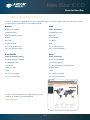
1.3 - HELP & TECHNICAL SUPPORT
For have any questions regarding the use of this equipment, please contact the representative from whom the system
was purchased, or alternatively use the following details:
Europe
USA
Andor Technology plc
Andor Technology
7 Millennium Way
425 Sullivan Avenue
Springvale Business Park
Suite # 3
Belfast
South Windsor
BT12 7AL
CT 06074
Northern Ireland
USA
Tel. +44 (0) 28 9023 7126
Tel. +1 (860) 290-9211
Fax. +44 (0) 28 9031 0792
Fax. +1 (860) 290-9566
Asia-Pacific
China
Andor Technology (Japan)
Andor Technology
4F NE Sarugakucho Building
Room 1213, Building B
2-7-6 Sarugaku-Cho
Lou Ke Time Square
Chiyoda-Ku
No. 103 Huizhongli, Chaoyang District
Tokyo 101-0064
Beijing 100101
Japan
China
Tel. +81-3-3518 6488
Tel. +86-10-5129-4977
Fax. +81-3-3518 6489
Fax. +86-10-6445-5401
The latest contact details for local representatives can be
found on our website via the following link:
andor.com/support
Page 16
New iStar ICCD
About the New iStar
1.4 - DISCLAIMER
The information contained herein is provided “as is” without warranty, condition or representation of any kind, either
express, implied, statutory or otherwise, including but not limited to, any warranty of merchantability, non-infringement
or fitness for a particular purpose.
In no event shall andor be liable for any loss or damage, whether direct, indirect, special, incidental, consequential or
otherwise howsoever caused whether arising in contract tort or otherwise, arising out of or in connection with the use of
the information provided herein.
COPYRIGHT AND PROTECTIVE NOTICES:
The copyright in this document and the associated drawings are the property of Andor Technology plc and all rights are
reserved. This document and the associated drawings are issued on condition that they are not copied, reprinted or
reproduced, nor their contents disclosed.
The publication of information in this documentation does not imply freedom from any patent or proprietary right of
Andor Technology plc or any third party.
1.5 - TRADEMARKS & PATENT INFORMATION
Andor, the Andor logo, New iStar & Solis are trademarks of Andor Technology plc. All other marks are property of their
owners. Changes are periodically made to the product and these will be incorporated into new editions of the manual.
Page 17
New iStar ICCD
About the New iStar
1.6 - ELECTRICAL & ENVIRONMENTAL SPECIFICATIONS
parameter
specification
Power supply ratings
100 - 240 V, 50 - 60 Hz, 1.6 A
Power consumption
85 W continuous
Location to be used
Indoor use only
Altitude
Up to 2,000 m
Operating temperature range
0°C to 40°C
Storage temperature
-20°C to +55°C
Operating relative humidity
< 70% non-condensing
Overvoltage category
CAT II
Pollution degree
2
Ingress protection rating
IP20
Electromagnetic compatibility
This is a Class A product. In a domestic environment this product may cause electromagnetic interference, in which
case the user may be required to take adequate measures
Cooling vent clearance
100 mm minimum
Dimensions (W x D x H)
Weight
110.7 x 231.0 x 137.2 mm [4.36 x 9.09 x 5.40 inches]
4.2 kg [9 lb 4 oz], power supply = 0.65 kg [1 lb 4 oz]
Note: Specifications are subject to change without notice
Page 18
New iStar ICCD
Introduction to the New iStar
SECTION 2 - INTRODUCTION TO THE NEW iSTAR
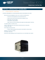
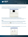
2.1 - COMPONENTS OVERVIEW
The main components of the Andor New iStar system are as follows:
•iStar camera head (see Figure 1 below), which contains the following items:
CCD sensor with integrated drive and readout electronics
Image Intensifier tube with associated drive and gating circuitry
Digital Delay Generator (DDG™)
Thermoelectric cooling interface
Input & output connectors (including USB, triggering and gating signal monitoring)
•1x USB 2.0 cable for connection to PC
•2x BNC to SMA cables (for synchronization with external events / equipment)
•1x Gate monitor cable
•Power Supply Unit (PSU) PS-90:
PowerPax SW4189 (Model STD-12090 with 3-pin Redel Connector Fitted)
•Software in CD format (if ordered)
•User Guide in CD format
•Performance sheet detailing the technical performance for your individual camera system
Figure 1: New iStar camera
Page 19
New iStar ICCD
Introduction to the New iStar
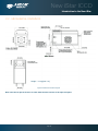
2.2 - Mechanical drawings
Weight = 4.2 kg [9 lb 4 oz]
Figure 2: New iStar mechanical layout
Note: The 10 mm optical distance is taken from the front surface of the input faceplate.
Page 20
New iStar ICCD
Introduction to the New iStar
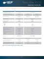
2.3 - CCD platform specifications - IMAGING SENSORS
MODEL
312T
334T
Total CCD matrix size (pixels)
512 x 512
Fibre optic taper magnification (std)
Ø 18 mm II
1:1
Ø 18 mm II
1:1
Ø 25 mm II
1.5:1
24 x 24 μm
100% fill factor
13 x 13 μm
100% fill factor
19.5 x 19.5 μm
100% fill factor
Effective CCD pixel size
Effective active area
1024 x 1024
12.3 x 12.3 mm
13.3 x 13.3 mm
Image pixel well depth
320,000 e-
100,000 e-
Register well depth
480,000 e-
150,000 e-
5.4 [7]
10 [14]
16 [20]
24 [50]
5 [7]
8 [12]
14 [18]
20 [50]
15.8 fps [28.5 fps]
633 fps
4.2 fps [7.3 fps]
333 fps
FVB
Crop mode (spectrum, 10 rows)
291 sps
5,556 sps
145 sps
3,450 sps
Fast Kinetics
4 rows
2 rows
32,150 Hz
55,250 Hz
29,850 Hz
-
2 to 10 e-/count
(software selectable)
1 to 5 e-/count
(software selectable)
Read noise (e-)
50 kHz
1 MHz
3 MHz
5 MHz
Maximum frame and spectral rates
Frame [2 x 2 binning]
Crop mode (frame, 10 rows)
Sensitivity
Linearity
Minimum temperature air cooled
[dark current, e-/pixel/sec]
Coolant chiller, coolant @ 10°C, 0.75 l/min
[dark current, e-/pixel/sec]
Better than 99%
Ø 18 mm II
Ø 18 mm II
Ø 25 mm II
-30°C [0.4]
-30°C [0.2]
-25°C [0.4]
-40°C [0.12]
-40°C [0.1]
-35°C [0.15]
Note: All specifications are typical unless otherwise stated
Page 21
New iStar ICCD
Introduction to the New iStar
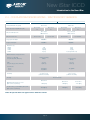
2.4 - CCD platform specifications - SPECTROSCOPY SENSORS
MODEL
320T
Total CCD matrix size (pixels)
Fibre optic taper magnification (std)
Effective CCD pixel size
Effective active area
340T
1024 x 255
2048 x 512
Ø 18 mm II
1:1
Ø 25 mm II
1:1
Ø 18 mm II
1:1
26 x 26 μm
100% fill factor
18 x 6.7 mm
Ø 25 mm II
1:1
13.5 x 13.5 μm
100% fill factor
25 x 6.7 mm
18 x 6.9 mm
25 x 6.9 mm
Image pixel well depth
500,000 e-
100,000 e-
Register well depth
550,000 e-
150,000 e-
Read noise (e-)
50 kHz
1 MHz
3 MHz
5 MHz
7 [9]
12 [13]
19 [20]
25 [32]
6 [8]
9 [12]
12 [18]
focussing mode only
Maximum frame and spectral rates
Frame [2 x 2 binning]
Crop mode (frame, 10 rows)
15.9 fps [28.9 fps]
320 fps
2.5 fps [5.6 fps]
184 fps
FVB
Crop mode (spectrum, 10 rows)
322 sps
2,941 sps
135 sps
1,825 sps
Fast Kinetics
4 rows
2 rows
16,610 Hz
26,590 Hz
16, 950 Hz
-
2 to 10 e-/count
(software selectable)
1 to 5 e-/count
(software selectable)
Sensitivity
Linearity
Minimum temperature air cooled
[dark current, e-/pixel/sec]
Coolant chiller, coolant @ 10°C, 0.75 l/min
[dark current, e-/pixel/sec]
Better than 99%
Ø 18 mm II
Ø 18 mm II
Ø 25 mm II
-30°C [0.4]
-30°C [0.2]
-25°C [0.4]
-40°C [0.12]
-40°C [0.1]
-35°C [0.15]
Note: All specifications are typical unless otherwise stated
Page 22
New iStar ICCD
Introduction to the New iStar
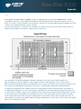
2.5 - Gen 2 Intensifier specifications
Photocathode model
18*-03
18*-04
18*-05.0
Useful aperture
18H-13
18H-83
18*-E3
Ø18 mm
25*-03
Ø 25 mm
Input window
Quartz
Quartz
MgF2
Quartz
Quartz
Quartz
Quartz
Photocathode type
W-AGT
W-AGT
W-AGT
WR
UW
WE-AGT
W-AGT
18
18
15
13.5
25
22
16
180 - 850
180 - 850
120 - 850
180 - 920
180 - 850
180 - 850
180 - 850
Image intensifier resolution limit
25 µm
30 µm
25 µm
25 µm
25 µm
25 µm
35 µm
Phosphor type
[decay time to 10%]
P43
[2 ms]
P46
[200 ns]
P43
[2 ms]
P43
[2 ms]
P43
[2 ms]
P43
[2 ms]
P43
[2 ms]
<2
<5
-
<2
<5
-
<5
< 10
-
< 50
< 100
<2
<5
-
<3
<7
-
> 1000
> 500
> 1000
> 850
> 500
> 300
> 1000
Peak QE @ room temperature
Wavelength range (nm)
Minimum optical gate width (ns)
U (Ultrafast)
F (Fast)
H (High QE)
Maximum relative gain
Maximum photocathode repetition rate (with
Intelligate™ OFF)
500 kHz (continuous)
Maximum photocathode repetition rate (with
Intelligate™ ON)
5 kHz (continuous)
Equivalent Background Illuminance (EBI) (e-/
pix/sec)
< 0.2
Page 23
New iStar ICCD
Introduction to the New iStar
2.6 - Gen 3 Intensifier specifications
Photocathode model
18*-63
18*-73
Useful aperture
18*-93
18*-A3
18*-C3
Ø18 mm
Input window
Glass
Glass
Glass
Glass
MgF2 + F/O +
Lumogen
Photocathode type
HVS
VIH
NIR
EVS
BGT
Peak QE @ room temperature
47.5
25.5
4
40
17
280 - 760
280 - 910
380 – 1090
280 - 810
< 200 - 910
30 µm
30 µm
30 µm
30 µm
40 µm
< 0.2
< 0.3
Wavelength range (nm)
Image intensifier resolution limit
Phosphor type
[decay time to 10%]
P43
[2 ms]
Minimum optical gate width (ns)
U (Ultrafast)
<2
F (Fast)
<5
Maximum relative gain
> 200
Maximum photocathode repetition rate(with
Intelligate™ OFF)
500 kHz (continuous)
Maximum photocathode repetition rate
(with Intelligate™ ON)
Equivalent Background Illuminance (EBI) (e-/pix/sec)
5 kHz (continuous)
< 0.1
< 0.3
Page 24
<2
New iStar ICCD
Introduction to the New iStar
2.7 – DDG™ specifications
The New iStar holds a fully integrated software-controlled digital delay generator (DDG)
with the following specifications:
Gate pulse delay & width
•Adjustable from 0 ns to 10 s in 10 ps steps
•Software controlled, pre-programmed or real-time
Trigger outPUTS
•3x output, +5V CMOS level with 50 Ω source impedance; can drive 5V into a non-terminating load or
2.5V into 50 Ω load; output synchronized triggers for auxiliary equipment, e.g. lasers, flash lamps, or National
Output A, B and C
Instrument™ hardware
•Individual delays control from 0 ns to 10 s in 10 ps steps
•Configurable polarity
•Software controlled, pre-programmed or real-time
Fire
•5V CMOS level reference signal for beginning and end of individual CCD exposure
•5V CMOS level reference signal to indicate when system is ready to accept external triggers. Signal goes high
Arm monitor
when system is ready to accept external triggers (after a complete readout has finished) including keep clean
and goes low when the exposure is finished
Gate & output A, B and C jitter
•35 ps rms (relative to external trigger signal)
Trigger INPUTS
•Trigger input for CCD and Digital Delay Generator
•Up to 500 kHz for Integrate-On-Chip mode
External trigger
•Software-configurable polarity, termination and trigger threshold
•Fast external software option for most rapid camera response to external trigger (CCD keep clean interruption)
– no need for pre-trigger pulse
Direct gate
•TTL input for exact external control of photocathode width and timing with smallest insertion delay.
Additional Controls
Gate monitoring
•AC coupling from photocathode to monitor exact photocathode On/Off switching and timings
Insertion delay
•< 19 ns in direct gate operation
Page 25
New iStar ICCD
Introduction to the New iStar
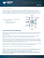
2.8 - Cooling
The New iStar detector is cooled using a thermoelectric (TE) cooler which is a small, electrically powered devices with
no moving parts, making it very reliable and convenient. A TE cooler acts as a heat pump, i.e. it achieves a temperature
difference by transferring heat from its ‘cold side’ (the CCD-chip within the New iStar camera head) to its ‘hot side’ (the
built-in heat sink).
Therefore the minimum absolute operating temperature of the New iStar sensor depends on the temperature of the heat
sink. The advanced thermal design of the New iStar means that a maximum temperature difference of over 60ºC can be
achieved. The maximum temperature difference that a TE device can attain is dependent on the following factors:
•
Heat load created by the CCD sensor, fiber-optic coupling to the intensifier and camera head design
•
Number of cooling stages of the TE cooler
•
Operating current
•
Operating temperature of TE cooler
The minimum temperature, to which the sensor within the New iStar can be cooled, will be dependent on either the room
temperature (when air-cooling is employed) or the coolant temperature circulating through the heat sink (when liquid
cooling is utilized).
2.8.1 - Air Cooling
Air cooling is the most convenient method of removing heat from the detector head, but it will not achieve as low an
operating temperature as water cooling. Even with a fan, a heat sink typically needs to be 10ºC hotter than the ambient
(room) temperature to transfer heat efficiently to the surrounding environment. Therefore the minimum CCD temperature
that can be achieved will be dependent on the room temperature.
The table below is a guide to the minimum achievable cooling for various ambient temperatures. Performance of
individual systems will vary slightly.
Air Temperature
CCD Temperature
Ǿ 18 mm
Ǿ 25 mm
20ºC
-30ºC
-25ºC
30ºC
-25ºC
-20ºC
40ºC
-20ºC
-15ºC
Table 1: New iStar air cooling performance versus image intensifier size
Notes:
1. The relationship between the air temperature and the minimum CCD temperature in the table is not 1:1.
This is because TE coolers become less efficient as they get colder
2. System cooling performance should be considered in terms of the minimum dark current achievable,
rather than absolute temperature. For dark current specifications, please refer to the specification sheet
for your camera
Page 26
New iStar ICCD
Introduction to the New iStar
2.8.2 - Fan Settings
The cooling fans can be switched On or Off simultaneously, which is useful if working with experimental configurations
which are extremely sensitive to vibration. The vast majority of applications, including LIBS or plasma imaging or
spectroscopy set-ups, can be used with the integral fans running, since the associated vibrations impact are negligible.
However some applications can be extremely sensitive to even the smallest of vibrations (such as when combining an
optical set-up with Atomic Force Microscopy - (AFM) and it can be useful to temporarily turn off the fans for the duration
of the acquisition.
If the fans are turned off, the usable range of acquisition parameters will be reduced (depending on the ambient
conditions) and can limit both the maximum gating frequency and the minimum cooling performance achievable. Once
a dataset has been acquired with the fans switched off, it is recommended that they be turned on again and the camera
head allowed to thermally re-stabilize (i.e. dissipate the excess heat built up in the heatsinks from both the Peltier cooler
and gating circuitry) before the next acquisition can begin.
Figure 3: Fan control interface in Solis software.
2.8.3 - Water Cooling
Circulating water is a very efficient method of removing heat from the heatsink. The heatsink temperature will be closely
coupled to the temperature of the circulating water and the cooling performance achievable will be dependent upon the
water temperature. Water cooling, either chilled though a refrigeration process or re-circulated (i.e. water which has been
forced air cooled then pumped) allows lower minimum operating temperatures than air cooling.
The table below is a guide to the minimum CCD operating temperatures for various water temperatures. Performance of
individual systems will vary slightly.
Water Temperature
CCD Temperature
Ǿ 18 mm
Ǿ 25 mm
10°C
-40ºC
-35ºC
15°C
-38ºC
-33ºC
20°C
-36ºC
-31ºC
25°C
-34ºC
-29ºC
Table 2: New iStar water-assisted cooling performance versus image intensifier size
Page 27
New iStar ICCD
Introduction to the New iStar
2.8.4 - Condensation
Condensation may be seen on the outside of the camera body if the temperature of the liquid coolant is too low, or if the
coolant flow is too great. The first signs of condensation will usually be visible around the connectors where the water
tubes are attached. In such circumstances, system should be switched off and camera wiped with a soft, dry cloth. It is
likely there will already be condensation on the cooling block and cooling fins inside the camera. The following actions
should be carried out:
•
Camera should be set aside to dry for several hours before attempting to re-use
•
Dry gas should then be blown through the cooling slits on the side of the camera to remove any residual
moisture
•
Warmer water or reduced flow should then be used when the device is started again
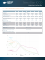
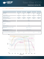
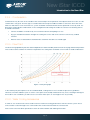
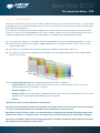
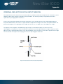
2.8.5 - Dew Point
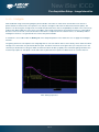
The Dew Point graph below plots the relationship between relative humidity and Dew Point at varying ambient temperature.
This can be used to calculate the minimum temperature the cooling water should be set to in order to avoid condensation.
Figure 4: Dew point graph
In the relatively dry atmosphere of an air-conditioned lab, cooling water at 10ºC should not present any problems.
However, in humid conditions (such as exist in some parts of the world) condensation may occur, resulting in damage to
the head. In such conditions you will have to use warmer water (20ºC or even higher if it is very humid).
2.8.6 - Water Cooling Accessories
A chiller or a re-circulator unit can be used to achieve maximum cooling performance with the camera system. These
units circulate coolant through hoses connected to the coolant channel within the camera head.
Please refer to the New iStar specification sheets for further details and ordering information.
Page 28
New iStar ICCD
Introduction to the New iStar
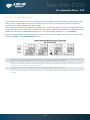
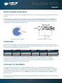
2.9 - Connectors
Water
connection
External
trigger
Output A, B, C
Arm monitor
Direct gate
Power
connector
Gate monitor
Earthing stud
USB 2.0 (optional
lockable interface)
On/Off switch
i2c
Figure 5: Rear & side views showing connectors interface
The user can synchronize the readout of the New iStar camera to external events / equipment by means of the SMA
receptacles. The functions of each are detailed below:
•
Ext Trig (External Trigger): TTL compatible input which is used to initiate data acquisition by the camera
•
Digital Delay Generator Outputs A, B & C: Programmable 5V CMOS level outputs used to synchronize
external events / equipment with operation of the New iStar
•Fire: 5V CMOS level reference signal relating to the CCD exposure time. This output remains high during the
charge / signal accumulation period, i.e. the time during which charge from the image area is not being read-out
•
Arm: 5V CMOS level reference signal to indicate when system is ready to accept external triggers. Signal goes
high when system is ready to accept external triggers after a readout sequence has finished, and goes low
when the exposure is finished
•
Direct Gate: TTL compatible input used to directly gate the photocathode of the image intensifier tube, i.e.
switch it On and Off. The photocathode is On when the input is high. User should provide (electrical) pulse
width and appropriate gate pulse delay
•
Gate Monitor: Enables user to monitor the accurate, actual On and Off switching of the photocathode
Page 29
New iStar ICCD
Introduction to the New iStar
The other connection points are as follows:
•
USB 2.0: A USB 2.0 compatible cable can be connected between the USB socket and a PC. Optional locking
connection is also available
•
I2C: The user can communicate with other I2C devices by means of the 5-way receptacle (Fischer P/N DBP 102
A 054 – 130) on the rear of the New iStar. The pin-out of this connector is shown below:
Pin
Function
1
SHUTTER (ttl)
2
I2C CLOCK
3
I2C DATA
4
+5 V
5
GROUND
Table 3: I2C connection (facing in) with pin-outs
•
Power: A 3-pin power connector is fitted for power connection, with the following pinout:
Figure 6: Power connector pin-outs. Matching cable connector is 3-pin Redel no. PAH.N0.3GL.LC65G
•
Earthing stud: Means of providing protective earth connection to camera head when it is not, or cannot be
provided via the 3-pin power connector
Before inserting the power connector, ensure that the orientation is correct. Never forcibly insert the
connector, otherwise damage to the equipment will occur.
Page 30
New iStar ICCD
Introduction to the New iStar
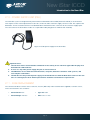
2.10 - Power Supply Unit (PSU)
The New iStar system is designed to be powered from an SW4189 external PSU (Andor P/N PS-90) as shown below.
This requires an AC mains input between 100-240 V, 47-63 Hz and a maximum supply current of 1.6A. The output of the
SW4189 is 12V DC at 9.0A maximum. The SW4189 PSU is fitted with an IEC connector for the electrical supply input.
The connection to the New iStar is made via a 3 pin Redel cable plug (Part No. PAH.N0.3GL.LC65GZ).
Figure 7: PS-90 power supply for the New iStar
Important notes:
1. The electrical mains lead should be certified for in the country of use and when applicable the plug must
be fitted with a 240 V 5A fuse
2. If users use any other power supply, they do so at their own risk
3. The SW4189 is for use with telecommunications, computer, industrial controllers & OA systems, and
must only be used indoors
4. The PS-90 is the only external power supply recommended for use with the New iStar camera. If this unit
fails or is damaged, the local Andor representative should be contacted for a replacement.
2.11 - Fuse replacement
The camera itself does not have a fuse. However, if a U.K. (BS 1363) mains lead has been supplied, it contains a fuse,
whose characteristics are as follows:
•
Rated Current: 5 A
•
Type: BS 1362
•
Rated Voltage: 240 Vac.
•
Size: 0.25 × 1 inch
Page 31
New iStar ICCD
Introduction to the New iStar
2.12 - Additional optional accessories
A lens (instead of a spectrograph) may be connected to the ICCD detector for imaging applications. The following items
are recommended for connection of standard lens types:
•C-Mount Lens Adaptor Kit (P/N LM-C), comprising C-mount adaptor,
spacer tubes, screws & allen key.
•Nikon F-Mount Lens Adaptor (P/N LM-NIKON-F)
•Nikon F-mount adaptor with shutter (P/N LMS-NIKON-F-NS25B)
Note: Although ICCDs efficiently act as optical shutters, the use of a mechanical shutter is recommended
when camera is not used to protect the photocathode from “passive” photo-bleaching.
2.13 - Spectrograph compatibility
The New iStar series is also fully compatible with Andor’s Shamrock spectrograph (163, 303, 500 and 750 mm focal
lengths) family and Mechelle 5000, Echelle spectrograph for broadband LIBS.
Spectrograph mounting flanges and software control are available for a wide variety of 3rd party spectrographs including,
McPherson, JY/Horiba, PI/Acton, Chromex/Bruker, Oriel/Newport, Photon Design, Dongwoo, Bentham, Solar TII and
others. Please contact your local representative for further details.
2.14 - Software
If ordered, Andor Solis Software or Andor Software Development Kit (SDK) is supplied on a CD and provides full control
of the New iStar camera system, including acquisition set-up, signal aquisition and data manipulation.
Solis and SDK provide simultaneous control of the Andor New iStar, Andor Shamrock and Andor Mechelle as well as a
range of 3rd party motorized spectrographs.
For further details of how to use the Solis software package, please refer to Section 4.
Page 32
New iStar ICCD
Installing the New iStar
SECTION 3 - INSTALLING THE NEW ISTAR
Prior to commencing installation, user should refer to the safety and warning information at the beginning of this manual.
3.1 - Mechanical CONNECTION TO the new istar
3.1.1 - Attaching to a Spectrograph
The New iStar can be easily connected to Andor’s Shamrock spectrograph. If the New iStar and Andor’s spectrograph
have been ordered at the same time, the system will arrive already pre-aligned and integrated. Outside this scenario including matching the New iStar to a third-party spectrograph - the following generic instructions should be followed:
1. Bolt the detector to the camera mounting flange, ensuring that the head is correctly orientated and that the
appropriate O-ring is inserted at the front of the detector head.
2. Attach the camera mounting flange to the spectrograph, ensuring that the appropriate O-ring is in place
between both detector flange and spectrograph flange.
3. Secure all four attachment screws so that the detector head, the flanges and the spectrograph are fitted together
securely in order to allow correct grounding through the connector cable. Good grounding maintains the low
noise performance of the detector, and in severe environments may prevent the instrument from damage.
3.1.2 - Attaching to a Lens System
The Andor New iStar can also be easily connected to a lens system for imaging purposes. Andor local representative
can supply details of the available adaptors for connecting the detector head to various manufacturers’ lenses. The
following general instructions should be followed:
1. When attaching the New iStar to a lens adaptor (C-Mount or F-Mount for example), ensure first that the
adpater is correctly orientated and aligned. Ensure that the appropriate O-ring is inserted between the camera
front plate and the lens adaptor plate. In the case of the C-Mount, place the side of the adaptor that is flush
with the brass insert towards the New iStar front plate. Ensure that all four attachment screws are secured to
the adaptor.
2. Attach the appropriate lens into the brass insert (C-Mount) or bayonnet interface (F-Mount) of the lens adaptor.
3.1.3 - Attaching to Nounting Posts
Three ¼ -20 UNC threaded holes are located on the underside of the unit. Drawing in section 2.2
provides precise location of these mounting holes.
Page 33
New iStar ICCD
Installing the New iStar
3.2 - Coolant hose inserts
Two barbed coolant hose inserts are supplied as standard with the New iStar camera, suitable for connection to 6 mm
(0.25”) internal diameter soft PVC tubing / hose. The recommended tubing should have 10 mm (0.4”) outside diameter,
i.e. a wall thickness of 2 mm (0.08”). Alternative hose dimensions and materials should be thoroughly tested to ensure
a leak tight seal is achieved with the barbed inserts. Once the hose has been secured to the barb, connection to the
camera is achieved by clicking hose inserts into the quick-release couplings on the rear of the camera head.
Before attempting to remove the hose connection, user should ensure that all water has been drained from the hoses
and integral coolant channel within the camera head. Care must be taken to avoid permanent damage to the camera
system resulting from either leakage of coolant during connection / removal of hoses or spillage of any residual coolant
contained within the camera head once the hoses have been removed.
Removal of the coolant hoses is achieved by slightly pulling the barbed connector, whilst at the same time depressing
the collar on the quick-release couplings, which releases the hose insert as shown below:
Collar
Figure 8: Removal of coolant hose inserts from quick release couplings on camera head
Some mains supply water are heavily mineralized, (i.e. “Hard”) which could cause deposits in the water
circuit inside the camera. This can reduce the flow-rate and affect the cooling preformance. It is therefore
recommended to use de-ionized water (without additives) as the coolant.
The specified cooling performance of the camera can be achieved with coolant flow rates of 0.75 litres per
minute, and the maximum recommended pressure of coolant circulating through the camera head is 2 bar.
In the event that replacement hose inserts / barbs are required, the local Andor representative should be contacted.
Important note: The temperature of liquid coolant circulated through the camera head should always be
above the dew point. Use of coolant at or below the dew point will result in permanent damage to the
camera head, due to formation of condensation on internal components. Section 2.8.5 provides further
details on this point.
Page 34
New iStar ICCD
Installing the New iStar
3.3 - Electrical connections
Prior to applying any power or triggering signals to the camera. The following recommendations should
be followed:
•
As part of the safety features of the New iStar system, the product is designed to have a protective earth
connected via the earth pin on the mains plug supplying the SW-4189 (PS-90). It is important to ensure that
this is connected to the buildings protective earth system, independently of the earth used for electrically noisy
instruments such as pulsed lasers.
•
When a protective earth is NOT provided to the camera head through the 3-pin power connector, the earthing
stud on the rear of the New iStar camera head MUST be connected to the buildings protective earth system.
The gauge of cable used for this connection must be 20 AWG or lower (i.e. wire diameter ≥ 0.812 mm).
•
The equipment should be positioned in such a way that the mains supply plug/cord can be easily accessed for disconnection.
•
Section 2.9 to should be used to identify correctly the plug location for the different interfaces, including power,
i2c as well as the comprehensive input / output connections
•
Prior to connecting the USB cable to the PC or laptop, software and USB driver installation instructions in
Section 3.4 should be followed.
Page 35
New iStar ICCD
Installing the New iStar
3.4 - INSTALLING SOFtware and usb drivers
3.4.1 - Minimum Computer Requirements
•
3 GHz Quad Core or 2.4 GHz multi core processor
•
2 GB RAM
•
100 MB free hard disc to install software (at least 1 GB recommended for data spooling)
•
USB 2.0 High Speed Host Controller capable of sustained rate of 40 MB/s
•
Windows (XP, Vista or 7) or Linux
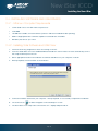
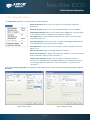
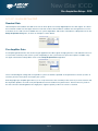
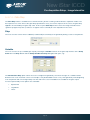
3.4.2 - Installing Solis Software and USB Driver
1. Terminate & exit any programmes which are running on the PC.
2. Insert the Andor Solis CD. The InstallShield Wizard should now start. If it does not start automatically, run the
file setup.exe directly from the CD.
3. Select appropriate location for installation of software and drivers on your computer / network.
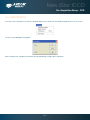
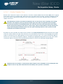
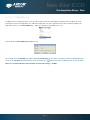
4. When prompted, select New iStar as shown below.
5. Continue installation and restart your computer - when prompted - to successfully complete the installation.
6. The shortcut icon
for Solis will appear on the desktop on re-start.
7. The New iStar is now ready to be connected to a PC / laptop and powered on.
Page 36
New iStar ICCD
Solis Software Operation
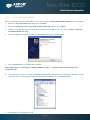
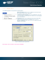
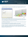
3.4.3 - New Hardware Wizard
When the New iStar camera is connected to a PC for the first time, the Found New Hardware Wizard screen will appear.
1. Select the ‘No, not this time only’ option then click Next> .
2. Select the ‘Install from a list or specified location (Advanced) option then click Next>.
3. Navigate to the directory where the Andor Solis software was installed to on the PC, then click Next> so that the
Installation Wizard can start.
4. When the hardware installation has been completed, the following screen will appear.
5. Click the Finish button to complete the installation.
Note: If the camera is connected to a different USB port, steps 1 – 5 will have to be repeated on the first
connection only.
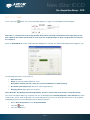
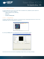
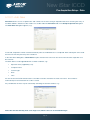
6. Check that the New iStar is correctly recognized and installed by opening the Device Manager in Windows, System
Properties section. The New iStar will be showing under the LibUSB root, as highlighted below:
7. The New iStar is now ready to be used.
Page 37
New iStar ICCD
Solis Software Operation
SECTION 4 - SOLIS SOFTWARE OPERATION
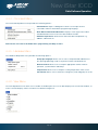
4.1 - STARTING THE APPLICATION
On the computer / laptop desktop, click on the
icon. The following Solis splash screen appears:
The Main Window then appears, e.g.:
Page 38
New iStar ICCD
Solis Software Operation
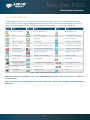
4.2 - Main Window
The Main Window is the user ‘entry point’ to the system. The menu options allow the user to either execute specific
functions directly, or launch further windows/dialog boxes to access more comprehensive functionalities. Some menu
options on the Main Window are also accessible through quick-launch buttons, as shown in the table below:
Icon
Title
Icon
Title
Icon
Title
Open file / program
Select sub-image area
Image display mode
Print
Select autoscale area
Change display color palette
Save
Reset scale
Time stamp settings
Real-time acquisition
Rescale data
Play kinetic series sequence
Take signal
Acquistion autoscale (live window)
Pause kinetic series sequence
Abort acquistion
99 to 1 contrast ratio adjustment
Stop kinetic series sequence
Setup acquisition
Data histogram display
Playback autoscale - Off
Run-time control
Region of interest settings
Baseline correction
Shutter control
File information
Periodic table
2D display mode with peak labels
Temperature control - Off
Run program
2D display mode
Temperature control - On
Command line
3D display mode
Help
Spurious noise filter
Table 4: Main window quick-launch buttons
Note: Some menu titles and buttons appear on the Main Window only under certain circumstances as shown on
the next sections.
Note: Icons are grouped by functionalities on dynamic display bars, which can be enabled / disabled through the
View menu.
Page 39
New iStar ICCD
Solis Software Operation
• The Display menu and its associated buttons will not appear until you open a Data Window is opened, e.g.:
• The Edit & Search menus and their associated buttons appear only when a Program Editor Window is active, e.g.:
4.2.1 - Main Window Status Bar
The following information is displayed on the bottom line of the display:
•
Current temperature status
•
Autoscale acquisition status
•
Sub-area dimension and location
•
Acquisition mode
•
Data type
•
Readout speed, No of bits and amplifier in use
Page 40
New iStar ICCD
Solis Software Operation
4.3 - HOT KEYS
Hot keys (or shortcuts) are shown in the following tables, enabling user to work with the system directly from the keyboard.
Key stroke(s)
Description
F5
Take signal
F6
Autoscale acquisition
Ctrl + B
Take background
Ctrl + R
Take reference
Esc
Abort acquisition
Table 5: Data acquisition Hot Keys
DISPLAY MODE
KEY STROKES
DESCRIPTION
2D
3D
+
Expand (‘Stretch’) data-axis
ü
ü
ü
-
Contract (‘Shrink’) data-axis
ü
ü
ü
Ins
If maintain aspect ratio off, expand x-axis.
If maintain aspect ratio on, expand x-axis and y-axis
ü
ü
ü
Del
If maintain aspect ratio off, contract x-axis.
If maintain aspect ratio on, contract x-axis and y-axis
ü
ü
ü
/
On image, if maintain aspect ratio off, expand y-axis.
On image, if maintain aspect ratio on, expand x-axis and y-axis.
Home
Move cursor furthest left
ü
ü
ü
End
Move cursor furthest right
ü
ü
ü
PgUp
Scroll up through track
ü
ü
ü
PgDn
Scroll down through tracks
ü
ü
ü
Shift + PgUp
Move to next image in series
ü
ü
ü
Shift + PgDn
Move to previous image in series
ü
ü
ü
Left Arrow
Move cursor left
ü
ü
ü
Right Arrow
Move cursor right
ü
ü
ü
Up Arrow
Scroll trace up (on image: move cursor up)
ü
ü
ü
Down Arrow
Scroll trace down (on image: move cursor down)
ü
ü
ü
Shift + Left Arrow
Scroll trace/image left
ü
ü
ü
Shift + Right Arrow
Scroll trace/image right
ü
ü
ü
Ctrl + Left Arrow
Peak search left
ü
ü
ü
Ctrl + Right Arrow
Peak search right
ü
ü
ü
F7
Toggle Palette
ü
ü
ü
F8
Reset
ü
ü
ü
F9
Rescale
ü
ü
ü
Alt + F9
Toggle Rescale Mode
ü
ü
ü
Ctrl + F9
Scale to Active (see Section 4 - Displaying Data) section)
ü
ü
ü
F10
File information
Table 6: Data window Hot Keys
Page 41
IMAGE
ü
New iStar ICCD
Solis Software Operation
Key stroke(s)
Description
Ctrl + N
New program
Ctrl + E
Run program
Esc
Abort acquisition / program
Ctrl + L
Command line
Ctrl + F1
Context sensitive help on reserved words in the Andor Basic programming language.
(Program Editor Window must be active).
Ctrl + S
Save
Ctrl + P
Print
Table 7: Andor Basic Programming Language Hot Keys
Page 42
New iStar ICCD
Solis Software Operation
4.4 MENU SELECTION
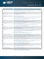
4.4.1 File Menu
Open: Opens a selected data file or program file
Close: Closes a selected data file or program file
Send To: Allows user to send selected sif or program files by e-mail
Color scheme: Setup of alternative color for background, acquisition window, data
set or program window
Save: Saves a selected data file or program file with a default (or current) filename
Save As: Saves a selected data file or program file with a user-defined filename
Export As: Allows user to export sif files to alternative formats (e.g. JPEG, TIFF)
Batch Conversion: Allows simultaneous conversion of large batches of data files from a
specified location to a particular format and a specified location
Virtual memory : Presets the disk storage system memory buffer size for extended
kinetic acquisitions
Additional FITS Keys: Allows addition of user’s own FITS information
Configuration Files: Loads or saves custom acquisition mode settings
New Program: Launches a program editor window for Andor Basic
Run Program: Runs Andor Basic program in active window
Run Program by Filename: Runs an Andor Basic program from a specific location
Custom Program Button: Adds or removes button shortcut for specific Andor Basic
programs
Start Program Setup: Allows automatic loading of Andor Basic program from a specific
location on Solis software launch
Remove Start Program: Deactivates automatic program loading on Solis software
startup
Print Preview: Allows preview of a sif or program file prior to printing
Print: Prints a selected sif or program file
Page Setup: Allows setting of document printing characteristics
Setup footnotes: Allows setting of footnotes associated with data file to be printed
Select another system: Allows toggling between several Andor detectors connected to
the current PC / laptop platform
Exit: Exits the Solis software
Page 43
New iStar ICCD
Solis Software Operation
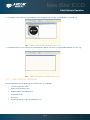
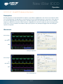
4.4.2 - Acquisition Menu
The Acquisition drop-down menu provides the following options:
Setup Acquisition: Allows user to set-up the CCD & Intensifier acquisition
parameters
Setup Data Type: Allows user to select the data windows X-axis unit display
Notify On Completion: Allows user to either start an application (.exe file) or play
a user-defined sound on completion of an acquisition sequence
Take Signal: Starts a data acquisition based on the current CCD & Intensifier
acquisition parameters
Take Background: Instructs the system to acquire raw background data based
on predefined shutter or image intensifier settings
Take Reference: Instructs the system to acquire reference signal from external
(light) source
Abort Acquisition: Stops the existing acquisition sequence
Autoscale Acquisition: Configures the acquisition window to scale automatically
during acquisition sequence when selected (‘ü‘)
Temperature Warnings: Displays any messages associated to setups or
processes incompatible with the standard operation of the temperature control
e.g. starting acquisition while sensor is still cooling down - only active when
selected (‘ü‘)
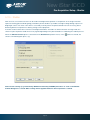
Selecting the Setup Acquisition menu brings the following interfaces which will be described and detailed throughout
Section 5.
Figure 9: CCD setup tab
Figure 10: Gating setup tab
Page 44
New iStar ICCD
Solis Software Operation
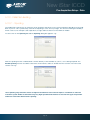
4.4.3 - Calibrate Menu
The Calibrate drop-down menu provides the following options:
Manual X-Calibration: Allows users to calibrate the x-axis of the active
data window through manually setup values
X-Calibration by Spectrograph: Allows user to calibrate the x-axis of the
active data window via specific dispersion calibration from a spectrograph
(see screenshot below)
Change Units: Allows user to change the x-axis units of an active data
window which has been previously calibrated e.g. cm-1, nm or eV
Remove X-Calibration: Allows user to remove any calibration previously
applied to a data window
Figure 11: X-Calibration by Spectrograph interface
Spectrograph setup and calibration will be detailed in Section 8
Page 45
New iStar ICCD
Solis Software Operation
4.4.4 - Command Menu
The Command drop-down menu provides the following options:
Command Line: Opens a dialog box to allow user to input one-line
commands written in Andor Basic programming language
Show Mean and Standard Deviation: Displays mean signal value and/or
standard deviation from mean in the data windows header
Arithmetic Operations: Allows basic arithmetic data manipulation e.g.
addition, subtraction etc.
Note: Please also refer to the Andor Basic programming and Help sections.
4.4.5 - Hardware Menu
The Hardware drop-down menu provides the following options:
Setup Spectrograph: Allows user to select, setup and load calibration for
the spectrograph being used, in conjunction with the Andor detector
Shutter Control: Allows user to setup the appropriate shutter mode of
operation, synchronization and delays
Temperature: Allows user to setup the cooling temperature of the sensor
Fan Control: Allows user to switch the cooling fans (CCD and gater) On or Off
4.4.6 - View Menu
The View drop-down menu allows user to enable or disable quick-access icon bars display on the main Solis window, as
well as reset the display of these icon bars to a default arrangement:
Page 46
New iStar ICCD
Solis Software Operation
4.4.7 - Display Menu
The Display drop-down menu provides the following options:
Change Display Mode: Allows user to change the display mode (2D, 3D or
Image) of the acquired data
Add Data Window: Allows user to duplicate an active window data in a new
window with display mode of choice, i.e. 2D, 3D or Image
Preferences: Allows user to optimize display interface e.g. peak labelling and
2D/3D graphical display
Axis Setup: Allows user to select data display range and units
Sequence options: Allows user to playback kinetic series acquisitions from a set
of custom parameters
Rescale Data Mode: Allows user to select the display range of the data intensity
Data Histogram: Allows user to plot a histogram showing the signal data
intensity versus number of pixels holding the same intensity value
Scale to Active: Allows overlaid signal traces to be rescaled to the active set of
data range
Region of Interest: Allows user to define a specific area of interest (ROI) in an
acquisition window
4.4.8 - Window Menu
The Window drop-down menu provides the following options:
Cascade: All data windows appear overlaid and offset within the Solis software frame
Tile Horizontal: Arranges selected data windows along the horizontal direction within the Solis
software frame
Tile Vertical: Arranges selected data windows along the vertical direction within the Solis
software frame
Close All: Closes all currently opened data windows
Copy to Clipboard: Copies the active data set into Windows clipboard for pasting to a
particular program, e.g. Word, Paint etc.
Page 47
New iStar ICCD
Solis Software Operation
4.4.9 - Help Menu
The Help drop-down menu provides the following options: Solis Help: Opens the Andor Solis Help dialog
Andor Basic Help: Opens the Andor Basic Help dialog
Shamrock Help: Opens the Andor Shamrock spectrographs Help dialog (if available)
About: Provides information on the Solis version number
About LibTIFF: Provides information on the TIFF library version integrated in Solis
4.4.10 - Software Help
The Andor Solis software provides on-line help based on the same format as typical of Windows applications.
When the application is running, click the
button or press F1 key should used to access the Andor Solis help dialog.
In addition to the main on-line help, the system provides help that relates specifically to the Andor Basic programming
language. When working with a Program Editor window, context sensitive help is available on the ‘reserved words’ of the
programming language. With the cursor on or immediately after a reserved word, this specific help can be accessed by
Ctrl + F1.
If you have any suggestions as to how our software, hardware and documentation might be improved, please let us
know by contacting your local Andor representative (see Section 1.3).
Page 48
New iStar ICCD
Solis Software Operation
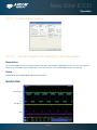
4.5 - RUN-TIME CONTROL
The run time control provides the user with the ability to control the following parameters in real-time using slider controls:
•
CCD exposure time
•
Gating mode
•
Gate width and delay
•
MCP gain
•
Output A, B and C delay and width
on the main
The controls are activated by clicking the button
window. When selected, the run time control appears, e.g.:
4.6 - ANDOR BASIC
Solis contains an embedded programming language called Andor Basic that can be used to setup custom acquisition
sequences. For example to run a sequence of 100 single scans with a 1 second delay between each scan, the following
program can be used:
create(#1, detectorx(), detectory(), 100) //creates a dataset #1 large enough to store all images
setkineticnumber(1)
//takes one image each time the loop iterates
for i = 1 to 100
run()
//acquires an image
#1{i} = #0{1}
//copies the acquired data from the #0 acquisition window to a location in #1
delay(1000)
//waits for 1000 milliseconds before progressing
next
Note: Documentation on the Andor Basic programming language is accessed via the Help menu in the main
application window
Page 49
New iStar ICCD
Pre-Acquisition Setup - CCD
SECTION 5 - PRE-ACQUISITION SETUP
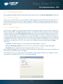
5.1 - SETTING TEMPERATURE
For accurate readings, the detector should first be cooled, as this will help reduce dark signal and associated shot noise.
To do this, either select the Temperature option from the Hardware drop-down menu on the main window:
or click the
button in the bottom-left of the screen. This will open up the Temperature dialog box :
Select the On radio button in the Cooler area.
The degrees (C) field in the Temperature Setting section will now be highlighted in blue and the Cooler will be indicated
as On, e.g.:
To adjust the temperature, either type in the new figure in the Degrees (C) box or move the slider bar down or up. Once
the desired temperature has been selected, click OK. The dialog box will disappear and the Temperature Control button
in the bottom-left of the screen will show the current temperature highlighted in red e.g.:
This figure will change as the head cools. Once the head has reached the desired temperature, the highlighted area
changes to blue.
You can also select the option to have the Cooler switched on as soon as you start the application. This is selectable in
the bottom-left of the Temperature dialog box.
Note: Please refer to Section 2.8 for details on minimal achievable temperatures
Page 50
New iStar ICCD
Pre-Acquisition Setup - CCD
5.2 - Fan control
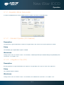
The state of the cooling fan can also be controlled. Select Fan Control from the Hardware drop-down menu as shown:
The Fan control dialog box will appear:
Select whether fans should be activated or deactivated during cooling and/or acquisition.
Page 51
New iStar ICCD
Pre-Acquisition Setup - CCD
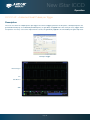
5.3 - CCD SETUP ACQUISITION
To select the mode of acquisition prior to data capture, the following steps should be followed:
button
•
Click the
•
Key in Ctrl+A
•
Select Setup Acquisition from the Acquisition drop-down menu:
The Setup Acquisition dialog box appears, e.g.:
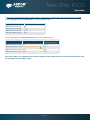
As user selects an acquisition mode, additional acquisition-related parameter fields will appear. The following matrix lists
the acquisition modes and the key set-able parameters:
Mode
Exposure
Time
Single Scan
ü
Accumulate
ü
Kinetic
ü
Accumulate
Cycle
Time
No.
Of
Accumulations
ü
ü
ü
Kinetic
Cycle
Time
No. in
Kinetic
Series
ü
ü
Note: The value entered in one field (e.g. exposure time) may affect the value in another field (e.g. acquisition
cycle time)
Note: Other modes such as photon counting or fast kinetics will be detailed specifically in following sections of
this user guide
Page 52
New iStar ICCD
Pre-Acquisition Setup - CCD
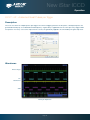
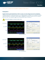
5.3.1 - Acquisition Modes & Timings
An acquisition is taken to be the complete data capture process that is executed whenever user selects Take Signal,
Take Background, or Take Reference from the acquisition menu, or whenever user clicks the Take Signal button. By
contrast, a scan (an “acquired scan” in the definitions that follow) is a single readout of data from the CCD-chip. Several
scans may be involved in a complete data acquisition. The minimum time required for an acquisition is dependent on
a number of factors, including the exposure time (i.e. the time in seconds during which the CCD collects light prior to
readout) and the triggering mode. Triggering modes are described in more detail later in this section.
5.3.1.1- Single Scan
Single scan is the simplest acquisition mode, in which the system performs one scan of the CCD.
The following parameters can then be changed:
•
Exposure Time
Note: Should user attempt to enter too low a value, the system will default to a minimum exposure time.
Page 53
New iStar ICCD
Pre-Acquisition Setup - CCD
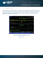
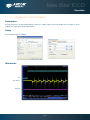
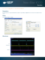
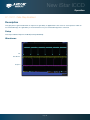
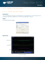
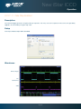
5.3.1.1.1 - Video
If user selects the
button, the system repeatedly performs a single scan and updates the data display.
Note: This is a useful mode for focusing the New iStar and for watching experimental events happening in real
time. However, this mode will not allow to save any of the acquired images or data, except for the last frame of
the sequence.
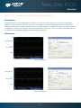
When the Video Mode tab on the setup acquisition dialog box is selected, the video mode dialog interface appears, e.g.:
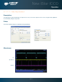
The following parameters can then be set:
•
Exposure Time
•
Delay: The interval required between scans.
Note: When entering too low a value, the system will default to a minimum delay
•
Resolution (sub-image area): Size of the sub-image (in pixels)
•
Binning pattern: Super pixel size (in pixels)
Note: When the ‘Use Settings From Standard Setup’ option is selected, these parameters cannot be altered.
The system will acquire data only as quickly as these can be displayed. If Take Background or Take Reference in video
mode are the chosen mode of operation, the system will perform one scan only. New data will continue to be acquired
and displayed until one of the following actions is being carried out:
•
Select Abort Acquisition from the Acquisition Menu
•
Click the
•
Press the <ESC> key
button
Page 54
New iStar ICCD
Pre-Acquisition Setup - CCD
5.3.1.2 - Accumulate
Accumulate mode allows user to ‘add together’ in the computer memory the data from a number of scans to create an
‘accumulated scan’ e.g.:
The following parameters can be entered in the Setup Acquisition dialog box:
•
Exposure Time
•
Accumulated Cycle Time: The period in seconds between each scan. This parameter is only available when
internal triggering is selected
•
No. of Accumulations: The number of scans to be added together
Note: This mode can be used to effectively improve the acquisition signal to noise ratio.
Page 55
New iStar ICCD
Pre-Acquisition Setup - CCD
5.3.1.3 - Kinetic Series
Kinetic series mode allows user to run, record and save a sequence of consecutive acquisitions in a single working
window. The following parameters are used to configure the acquisition:
•
Exposure Time
•
Kinetic Cycle Time: The time between the start of two consecutive scans within a kinetic series
•
Number in Kinetic Series: The number of scans taken in the kinetic series
This mode is particularly well suited to recording the temporal evolution of a process, and can also be used in
conjunction with accumulation mode for further signal-to-noise ratio enhancement
Note: If External trigger is selected the Kinetic Cycle dialog box will indicate the maximum achievable frame rate.
Page 56
New iStar ICCD
Pre-Acquisition Setup - CCD
5.3.1.4 - Fast Kinetics
Fast Kinetics mode allows access to exposure times (and time resolution) on a microsecond timescale, i.e. in the order of
magnitude of the CCD vertical shift speeds. However, in the case of ICCDs, the ultimate time-resolution will be dictated
by the photocathode gate time.
In Fast Kinetics the signal to be recorded is imaged across a certain section of the CCD, typically across the top rows
of the CCD sensor. The non-illuminated part of the CCD is used for storage of the consecutive images part of the same
acquisition sequence before readout. The overall sequence is recorded in one single acquisition window.
T1 - CCD keep clean sequence is interrupted, and useful signal builds-up on the user-defined top portion of a sensor
T2 - At the end of the exposure time, signal is rapidly shifted down by a pre-defined number of rows, and a second
exposure takes place
T3 - This process is repeated until the number of acquisitions equals the series length set by user
T4 - The sequence moves into the readout phase by shifting in turn the individual acquisitions to the readout register,
which is then read out
T1
T2
T3
T4
From the Setup Acquisition dialog box, the following parameters can be configured:
•
Exposure time: the exposure time also represents the cycle time of the Fast Kinetics series. There is no
separate parameter for a fast kinetics cycle time
•
Sub Area Height in rows
•
Number in Series: the number of time-sampled acquisitions in the series to be stored on the sensor. These will
depend on the sensor height and number of active rows selected
•
Binning
•Offset of the active area from the bottom of the detector
Note: Special offset flanges for Andor spectrographs are available so that active area of the sensor is positioned
across the spectrograph optical axis, where best optical performance can be achieved.
Note: When using fast kinetics mode, care should be taken to avoid (or greatly minimize) stray light falling on the
bottom of the sensor, i.e. outside the active area of the sensor, in order to avoid useful, stored signal corruption.
Note: The use of Andor’s Optomask for imaging applications should be considered to physically block unwanted
light falling on to the storage part of the sensor.
Page 57
New iStar ICCD
Pre-Acquisition Setup - CCD
5.3.1.5 - Cropped Sensor Mode
If an experiment demands the fastest image or spectrum acquisition rates, but cannot be constrained by the maximum
storage size of the sensor (as is the case for ‘Fast Kinetics Mode’), a specific ‘Cropped Sensor Mode’ can be set up
through the main acquisition set up window, e.g.:
In this mode, the user defines a ‘sub-array’ size from within the full image sensor area, such that it encompasses the
region of the image where change is rapidly occurring. The sensor subsequently ‘imagines’ that it is of this smaller defined
array size, achieved through software executing special readout patterns, and reads out at a proportionally faster frame
rate. The smaller the defined array size, the faster the frame rate achievable.
The cropped area must be positioned in the bottom-left of the sensor, thus the subject of study should be first positioned
in this area rather than centrally located.
Note: Special offset flanges for Andor spectrographs are available so that crop area of the sensor is positioned
across the spectrograph optical axis, where best optical performance can be achieved.
Note: When using crop mode, care should be taken to avoid (or greatly minimize) stray light falling on the top of
the sensor, i.e. outside the active ‘cropped’ area of the sensor, in order to avoid useful signal corruption.
Note: The use of Andor’s Optomask for imaging applications should be considered to physically block unwanted
light falling on to the upper part of the sensor.
Page 58
New iStar ICCD
Pre-Acquisition Setup - CCD
5.3.1.6 - Photon Counting
Photon Counting can only be successfully carried out with very weak signals, because as the name suggests, it involves
counting only single photons per pixel. If more than one photon falls on a pixel during the exposure, an ICCD cannot
distinguish the resulting signal spike from that of a single photon event, and thus the dynamic range of a single frame
exposure is restricted to one photon.
Under such ultra-low light conditions, ‘photon counting mode’ imaging carries the key benefit that it is a means to
circumvent the Multiplicative Noise, also known as ‘Noise Factor’. Multiplicative noise is a by-product of the Electron
Multiplication process and affects both EMCCDs and ICCDs. This gives the new ‘effective shot noise’ that has been
corrected for multiplicative noise.
Photon Counting mode does not measure the exact intensity of a single photon spike, but instead registers its presence
above a threshold value. It does this for a succession of exposures and combines the individual ‘binary’ images to create
the final image. As such, this mode of operation is not affected by the multiplication noise (which otherwise describes
the distribution of multiplication values around the mean multiplication factor chosen). The end result is that low light
images acquired through this mode of acquisition are improved by a factor of ~x2-2.5 Signal-to-Noise, compared to a
single integrated image with the same overall exposure time.
To successfully photon count with ICCDs, there has to be a significantly higher probability of seeing a ‘photon spike’
than seeing a darkcurrent/EBI ‘noise spike’. The lower the contribution of this dark noise sources to a single exposure
within the accumulated series, the lower the detection limit of photon counting and the cleaner the overall image will be.
Page 59
New iStar ICCD
Pre-Acquisition Setup - CCD
5.3.1.6.1 - Photon Counting in Real-Time
As the ICCD is continually scanned, the signal builds up in computer memory and can be viewed live on the screen.
Photon Counting can be selected and configured from the Acquisition Mode drop-down menu of the dialog box, e.g.:
Parameters to be set are:
•
Exposure Time per acquisition
•
Number of Acquisitions per Output Image or spectrum
•
Kinetic Series Length required.
The Photon Counting Threshold tab provides the following interface:
Min.Threshold and Max. Threshold values can be set to define the signal intensity range considered for the detection
of the single photons events. The new iStar photon counting mode allows selection of several ‘counting levels’ to
especially differentiate several photons from a single pixel or column - the latter is especially useful when working in FVB
mode. Each level is defined by a signal intensity in counts.
option selectable from the quick access button on the main window allows easy visualization of
The histogram
signal brackets population.
Page 60
New iStar ICCD
Pre-Acquisition Setup - CCD
5.3.2 - Readout Modes
The signal captured by a 2D CCD sensor can be read in several different ways, adapted to specific experimental
configurations. The main options available are:
•
Image (including sub-array and binning)
•
Multi-Track
•
Full Vertical Binning (FVB)
5.3.2.1 - Image Mode
The default image display mode is referred to as ‘full resolution image’, whereby signal information (in counts) of each
individual pixel of the CCD is reported and accessible, e.g.:
By selecting the Binning tab in the setup aquisition interface the following options appear:
This interface allows the user to tailor the image display through sub-arrays/sub-images, or binning.
Page 61
New iStar ICCD
Pre-Acquisition Setup - CCD
5.3.2.1.1 - Sub Image
For the purpose of initial focusing and alignment of the camera, or to increase the frame or spectral rate, user may select
a sub-image of the CCD chip. When the camera is running in sub-image mode, only data from the selected pixels will be
read out, and data from the remaining pixels will be discarded. To read out data from a selected area (or sub-image) of
the CCD, the radio buttons should be toggled to select the required resolution as shown below:
Note: The standard choices of sub-image configuration will vary with the CCD matrix used.
A custom sub-image can also be used to set a specific size and location of the desired aquisition area on the CCD chip.
To user-define a sub-image, the custom radio button should be selected so that the co-ordinate fields appear.
Draw
In addition to the previous methods of defining a sub-image on the sensor, a Draw option can be used to graphically
select the size and location of the sub-image. A full resolution image must first be acquired to provide the template on
which the sub-image will be drawn. The
button displays the Draw tool on the full resolution image.
Note: ‘Restore Absolute Co-ordinates in Data Set’ allows user to retain actual pixel X-Y co-ordinates on the CCD
5.3.2.1.2 - Image orientation
In image mode, the data can also be orientated in a specific way as they are acquired. The orientation of the image data
is accessible from the Image Orientation tab on the Setup Acquisition dialogue box e.g.:
Page 62
New iStar ICCD
Pre-Acquisition Setup - CCD
5.3.2.2 - Multi-track Mode
Multi-track mode allows creation of one or more individual aquisition tracks that can be defined (in rows) by the height
of each track, and the offset on the CCD-chip, which in effect ‘raises’ or ‘lowers’ the pattern of tracks from which the
charges will be read out.
In this way, the position of the tracks can be adjusted to match a light pattern produced on the CCD-chip by a fiberoptics bundle for example. To define multiple tracks on the CCD-chip can be defined under the Multi-track section from
the Readout Mode drop-down menu in the Setup Acquisition dialog box:
By clicking the
button, the following Setup Multi-track dialog box opens, e.g.:
There are two modes of operation, i.e. Standard or Custom.
•
In Standard mode, the user defines the Number of tracks, the Height & Offset. The software automatically
calculates the position of the tracks by distributing them evenly across the sensor.
•
In Custom mode, the user has the ability to define the tracks as required, e.g.:
The user can also save the position of the individual tracks to a file that can be reloaded later. The Load and Save
buttons are used to achieve this. The user can also utilize the Insert and Delete buttons to define or remove tracks. If
the Advanced button is clicked, the Advanced Multi-track options dialog box appears:
This allows the user to define the horizontal binning and position of all the tracks. The Transfer button can be used to
quickly load the automatically calculated tracks from the standard mode setup into custom mode.
Page 63
New iStar ICCD
Pre-Acquisition Setup - CCD
5.3.2.3 - Full Vertical Binning (FVB)
FVB allows the user to operate the CCD-chip as a linear image sensor (a photodiode array), typically for spectroscopy
applications. The charges from each column of pixels (each column being the chip height) are combined, or binned,
on the chip to give one single signal value per column. FVB mode is selected in the Setup Acquisition dialog box as
shown below:
For some spectrographs, it may be necessary to change the direction in which the data is displayed on screen. This is
accessible in the setup acquisition dialogue, in the FVB tab as shown below:
In some instances spectral rate can be more important than spatial/spectral resolution. For such applications, horizontal
binning can be applied by setting the desired binning format in the Horizontal Binning section of the acquisition setup
interface (see section 5.3.3.1) to a value greater than one.
Page 64
New iStar ICCD
Pre-Acquisition Setup - CCD
5.3.3 - Binning
Binning is a process that allows charge from two or more pixels to be combined on the CCD-chip prior to readout.
Summing charges on the CCD and doing a single readout gives better noise performance than reading out several
pixels and then summing them in computer memory. This is because each act of reading out charges from the CCD
contributes to noise.
Combining both the vertical and horizontal binning methods produces ‘superpixels’. These consist of two or more
individual pixels that are binned and read out as one large pixel. Thus the whole CCD, or a selected sub-area becomes a
matrix of superpixels.
On the one hand superpixels result in a loss of spatial resolution when compared to single pixel readout, but on the other
hand they offer the advantage of summing data on-chip prior to readout, thereby producing a better signal-to-noise ratio
and a higher frame rate.
5.3.3.1 - Vertical Binning
Charges from two or more rows of the CCD-chip are moved down into the shift register before the charges are read out.
The number of rows shifted depends on the binning pattern selected. Thus, for each column of the CCD-chip, charges
from two or more vertical elements are summed into the corresponding element of the shift register. The charges from
each of the pixels in the shift register are then clocked horizontally to the output amplifier and read out.
1. Single-Track: Charges are vertically binned and read out from a number of user-selected adjacent rows of
pixels on the CCD-sensor. The rows form a single track across the full width of the CCD-sensor.
2. Multi-Track: This mode differs from single-track in that user now defines two or more tracks (groups of rows)
on the CCD from which to read out charges. In processing terms, each track is treated as in single track.
3. Full Vertical Binning (FVB): Charges from each complete column of pixels on the CCD are moved down and
summed into the shift register, and the charge is then shifted horizontally one pixel at a time from the shift
register into the output node - in effect a value is read out for each complete column of the CCD-sensor. This
mode is typically used for spectroscopy (please refer to section 5.3.3.3).
The example below illustrates readout of data from adjacent tracks, each track comprising two binned rows of the sensor.
1
Exposure to light causes a pattern of charge (an electronic image) to build up on the frame (or ‘image area’) of the CCD-sensor.
2
Charge in the frame is shifted vertically by one row, so that the bottom row of charge moves down into the shift register.
3
Charge in the frame is shifted vertically by a further row, so that the next row of charge moves down into the shift register, which now contains
charges from two rows - i.e. the charges are vertically binned
4
Charges in the shift register are moved horizontally by one pixel, so that charges on the endmost pixel of the shift register are moved into the
output node of the amplifier.
5
The charges in the output node of the amplifier are passed to the analog-to-digital converter and are read out (digitized).
6
Steps 4 and 5 are repeated until the shift register is empty. The process is repeated from Step 2 until the whole frame is read out.
Page 65
New iStar ICCD
Pre-Acquisition Setup - CCD
5.3.3.2 - Horizontal Binning
In this configuration, charges from two or more pixels in the serial register are transferred into the output amplifier and
read out as one combined data value. Thus the charges from two or more of the horizontal elements are effectively
summed into the output amplifier before being readout.
In the example below (where each superpixel is of dimensions 2 x 2 pixels) charges from two rows is first binned vertically
into the shift register; then charges from two pixels of the shift register are binned horizontally into the output node of the
amplifier. The effect of the combined binning processes is a summed charges equating to a 2 x 2 ‘superpixel’.
Since this example initially involves binning charge from two rows, the process begins in the same way as the previous
example (see Steps 1 - 4 of Vertical Binning section).
(...4)
Charges from two rows have already been vertically binned into the shift register. Charges in the shift register are now moved horizontally by one
pixel, so that charges on the endmost pixel of the shift register are moved into the output node of the amplifier.
5
Charges in the shift register are again moved horizontally, so that the output node of the amplifier now contains charges from two pixels of the
shift register - i.e. the charges have been horizontally binned.
6
The charges in the output node of the amplifier are passed to the analog-to-digital converter to be read out.
7
Steps 4 to 6 are repeated until the shift register is empty. The process is repeated from Step 2 (in Vertical Binning section) until the whole frame
is read out.
Page 66
New iStar ICCD
Pre-Acquisition Setup
Section
- CCD
Title
5.3.4 - CCD Clocking Speed
5.3.4.1 - Vertical Pixel Shift
Shift speed
Shift Speed (µsecs) specifies the time taken clock (shift) charges from one row on the CCD sensor to the next. Speeds
which appear un-bracketed in the drop-down list are guaranteed to meet all the system specifications. In some
instances, using a slightly slower vertical shift speed may result in a slight increase in the single well capacity for imaging
applications. However it may also reduce the maximum frame/spectral rates achievable.
Bracketed vertical shift speed values are also available (CCD-model dependant) to achieve even faster acquisition rates.
However, with this setting the pixel well depth and charge transfer efficiency may be impacted.
Vertical Clock Amplitude Voltage
The vertical clock voltage amplitude can be used to increase the amplitude of the clock pulses used to perform row
shifts on the CCD. The normal setting is the default amplitude which has been set at the factory during the optimization
and testing of the camera. The other settings (if available) specify the voltage increase to be applied to this clock
amplitude. In some imaging applications, increasing this voltage can provide a slightly higher single pixel well depth and
improve charge transfer efficiency, at the expense of slightly higher CIC.
Application of higher voltage may be required in combination with the fastest of the bracketed vertical pixel shift speeds
in order to overcome image distortion effects that result from reduced charge transfer efficiency. Best practice is to
select the fastest vertical shift speed, then step the vertical clock voltage 1 unit at a time until distortive effects disappear
from the image.
Page 67
New iStar ICCD
Pre-Acquisition Setup - CCD
5.3.4.2 - Horizontal Pixel Shift
Readout Rate
Horizontal pixel shift readout rate defines the rate at which pixels are read (or digitized) from the shift register. The faster
the horizontal readout rate the higher the frame rate that can be achieved. Slower readout rates will generate less noise
in the data as it is read out. The available rates are system dependant, and can be selected from a drop-down list on the
Setup Acquisition dialog box, of which an example is shown below:
Pre-Amplifier Gain
Pre-amplifier gain determines the amount of gain applied to the video signal emerging from the CCD and allows the user
to control the sensitivity of the camera system. Depending on the system there are up to three options available. They
are again selected from a drop-down menu on the Setup Acquisition dialogue box:
These normalized gain settings will correspond to system sensitivities specified on the performance sheets (in terms of
electrons per A/D count) which accompany the system.
Selecting higher pre-amplifier gain values (i.e. x2 or x4) will increase the sensitivity of the camera (i.e. fewer electrons will
be required to produce one A/D count) and provide the lowest readout noise performance. However this may result in
the A/D converter saturating before the single pixel / register capacity of the CCD sensor is reached.
Page 68
New iStar ICCD
Pre-Acquisition Setup - Shutter
5.3.5 - Shutter
With an ICCD, a mechanical shutter can be used for background acquisition in complement of the image intensifier
optical shuttering (photocathode gating). Indeed the photocathode may exhibit some light leakage during exposure to
bright light source even when ‘Off’. But it is essentially used to protect the photocathode from unneccessary photobleaching between acquisitions or during storage of the equipment.
A shutter can be used to take a reference or background if FVB is selected. For either multi-track or image mode, the
shutter may be required to avoid unnecessary signals/light falling on the photocathode or CCD during the readout process.
When the Shutter Control option is selected from the Hardware drop-down-menu, or the
shutter control dialog box opens, e.g.:
button is clicked, the
Note: Certain settings (e.g. Permanently OPEN & Permanently CLOSED) take effect as soon as the Shutter
Control dialog box is closed. Other settings will be applied whenever data acquisition is started.
Page 69
New iStar ICCD
Pre Acquisition Setup - Shutter
•
In Permanently OPEN mode, the shutter will be open before, during and after any data acquisition. However if
the camera is to be left unattended for long periods, it is recommended that the shutter is closed.
•
Permanently CLOSED mode can be useful for taking a series of acquisitions in darkness (background) and do
not require the shutter to open between acquisitions. The shutter remains closed before, during and after any
data acquisition.
•
Fully Auto is the simplest shutter mode, as it leaves all shuttering decisions to the system. When a Take Signal
operation is performed, the shutter opens for the duration of the CCD exposure time.
•
If CLOSED for background mode is selected, any shutter driven from the shutter output of the camera will be
closed during background acquisition only.
•
The TTL (Transistor-Transistor Logic) buttons, TTL Low & TTL High, allow user to instruct the system as to how
it should control the opening and closing of the shutter i.e. open or closed status during high or low TTL states.
Note: The shutter pulse is not capable of driving a shutter. It is only a 5V pulse designed to trigger TTL & CMOS
compatible shutter drivers. The shutter pulse from the camera ca be directly connected to Andor Shamrock
spectrographs in order to control the internal shutter of these instruments, or to an Andor ACC-SD-VDM1000
external shutter driver for stand alone shutter operation.
Page 70
New iStar ICCD
Pre Acquisition Setup - Shutter
5.3.5.1 - Shutter Transfer Time
Shutters take a finite time to open or close and this is sometimes called the Shutter Transfer Time (STT). This is typically
in the order of a few tens of milliseconds, and will vary from one shutter type to the other. The STT should give enough
time for the shutter to open before acquisition starts, and enough time to close after acquisition finishes and before
readout commences.
Note: Mechanical shutters are limited to repetition rates of a few Hz for correct ‘opening’ and ‘closing’
operation. This frequency will vary from one shutter type to the other. If acquisition rate of the CCD
exceeds the maximum recommended shutter rate, then this will cause partial operation of the shutter
blades and potential damage to the device. At that stage, shutter should either be left fully opened (and
image intensifier photocathode becomes the sole signal shuttering interface in the system), or CCD
acquisition rate should be decreased.
By default, the value entered in the exposure time text box on the Setup Acquisition dialog box determines the length
of time the shutter will be in the open state. However, to accommodate the transfer time, the rising edge of the shutter
output is sent before the Fire output signal by an amount equal to the preset STT. The system automatically adds the
transfer time to the end of the acquisition sequence, introducing an appropriate delay between the start of the shutter
closed state and the commencement of the data being read out as shown in the following example diagram:
Important note: If no shutter is connected, the time to open or close should be set to 0. Setting the Time
to open or close to any other value will insert extra delays into cycle time calculations.
Page 71
New iStar ICCD
Pre Acquisition Setup - Data
5.3.6 - Acquistion and Data Types Selection
Some acquisitions, such as quantitative measurements or absorption / transmission / reflection require a degree of data
processing which can be executed and displayed seamlessly in Solis.
5.3.6.1 - Definitions of Data Types
Data processing and display involves the following bassline information:
•
Signal: Uncorrected raw data acquired via Take Signal. ‘Signal’, as used in the definitions of the calculations,
refers to ‘raw’ data from the detector and should not be confused with the possibly ‘processed’ data to be
found under the Sig tab of the Data window.
•
Background: Data in uncorrected counts, acquired in darkness
•
Reference: Background corrected data. Reference data is normally acquired from the light source, without the
light having been reflected from or having passed though the material being studied
5.3.6.2 - Data Display and Processing Modes
The data processing and display formats can be selected from the Acquisition drop down menu under Setup Data
Type, e.g.:
The descriptions of the different available data display and processing types are shown in Table 8.
Page 72
New iStar ICCD
Pre Acquisition Setup - Data
OPTION
FUNCTION
Counts
Counts represent raw, digitized data (i.e. no calculations have been performed on the data) from the EMCCD
detector’s analog to digital (A/D) converter. Please refer to the detailed performance sheet accompanying your
particular EMCCD detector for the number of electrons that correspond to 1 count.
Counts (Bg corrected)
Counts (Background Corrected) is digitized Data from the EMCCD detector’s analog to digital (A/D) converter,
where Background (or dark signal) has been removed.
Counts (Bg. Corrected) = Signal - Background
Counts (per second)
Counts ÷ Exposure Time.
Count (Bg corrected per second)
Counts (Bg corrected) ÷ Exposure Time.
%Absorptance
Represents the light absorbed by an object.
If Reference is the background corrected incident intensity, and Signal - Background the transmitted intensity
(i.e. the intensity of light which has passed through the material being examined), then:
% Absorptance = 100 x (1 - (Signal - Background) / Reference)
%Reflectance
Represents the light reflected by an object.
If Reference is the background corrected incident intensity, and Signal - Background the reflected intensity (i.e.
the intensity of light which has been reflected from the material being examined), then:
% Reflectance = 100 x (Signal - Background) / Reference
%Transmittance
Represents the light transmitted by an object.
If Reference is the background corrected incident intensity, and Signal - Background the transmitted intensity
(i.e. the intensity of light which has been transmitted through the material being examined), then:
% Transmittance = 100 x (Signal - Background) / Reference
Flatfield
Flatfield is used to remove any pixel-to-pixel variations that are inherent in the ICCD sensor. If Reference is the
background corrected incident intensity, the Signal is divided by the Reference so:
Flatfield = M x Signal / Reference
Where M is the Mean of Reference.
Absorbance units
A measure of light absorbed by an object (i.e. they represent the object’s Optical Density - OD). If Reference is
the background corrected incident intensity, and Signal - Background the transmitted intensity (i.e. the intensity
of light which has passed through the material being examined), then Transmission =
(Signal - Background) / Reference.
Absorbance Units are defined as Log10 (1 / Transmission).
Therefore: Absorbance Units = Log10 (Reference / (Signal - Background)).
Absorption Coefficient (/m)
Indicates the internal absorptance of a material per unit distance (m).
It is calculated as -loge t, where t is the unit transmission of the material and loge is the natural logarithm.
If Reference is the background corrected incident intensity, and Signal - Background the transmitted intensity
(i.e. the intensity of light which has passed through the material being examined), then:
Transmission = (Signal - Background) / Reference
and:
Absorption Coefficient = -loge ((Signal - Background) / Reference)
Attenuation
A measurement, in decibels, of light absorbed due to transmission through a material - decibels are often used
to indicate light loss in fiber optic cables, for instance.
If Reference is the background corrected incident intensity, and Signal - Background the transmitted intensity
(i.e. the intensity of light which has passed through the material being examined), then:
Attenuation = 10 x log10 ((Signal - Background) / Reference)
Data*Ref
Allows you to ‘custom modify’ the background corrected signal:
Data x Ref = (Signal - Background) x Reference Store Value
See the Andor Basic Programming Manual for similar operations.
Log 10
Calculates the logarithm to the base 10 of the background corrected signal counts.
Log Base 10 = log10 (Signal - Background)
Radiometry (Optional extra)
Allows you to calculate values for radiance or irradiance. The system requires that you supply calibration
details. This option must be ordered separately.º
Table 8: Data type and display available in Solis
Page 73
New iStar ICCD
Pre Acquisition Setup - Data
The illustration below shows a typical use of Background, Reference and Signal for computations such as
%Absorptance or %Transmittance:
For example, the % Absorption will be computed as:
100 x (1 - (Signal - Background) / Reference)
The default data type (used when capturing data and having not explicitly made a selection from the Data Type dialog
box) is counts.
If any data type other than counts or counts (Bg Corrected) are selected, user will have to perform Take Background
and Take Reference (in that order) before performing Take Signal.
Page 74
New iStar ICCD
Pre Acquisition Setup - Data
5.3.7 - Autoscale Acquisition
Prior to the Take Signal function being activated, autoscale acquisition can be selected from the Acquisition dropdown menu as shown below (or F6 on the keyboard):
•
With autoscale acquisition deselected, the display will remain the same size regardless of brightness settings,
button appears.
etc. When not selected, the
•
With autoscale acquisition selected, the system will configure the acquisition window (if necessary adjusting
button appears when
its scales in real time) so that all data values are displayed as they are acquired. The
selected on. The data are displayed in accordance with the selection made on the Rescale Data Mode on the
Display Menu:
Different scaling modes are available as follows:
•
Minimum & maximum (Min..Max)
•
Zero & maximum (0..Max)
•
Zero & 16383 (0..16383)
•
Minimum & 16383 (Min..16383)
•
Zero & 65535 (0..65535)
•
Minimum & 65535 (Min..65535)
•
Custom setting as required - user selectable min and max display range
Note: The histogram icon
can be used to adjust conveniently and in real time signal display scaling.
Page 75
New iStar ICCD
Pre Acquisition Setup - Data
5.3.8 - Data File Handling
5.3.8.1 - Spooling
The Andor Solis software has an extensive range of options that allows user to spool acquisition data direct to the hard
disk of your PC. This is particularly useful when acquiring a series of many images. The amount of data generated by a
kinetic series of, for example 1,000 acquisitions, is huge and more than most PC RAM can handle.
To select click on the Spooling tab and the Spooling dialog box appears e.g.:
With the spooling function enabled, data is written directly to the hard disk of you PC, as it is being acquired. The
Enable Spooling function should be selected as shown below, and user should enter the relevant stem name and
location root e.g.:
Note: Spooling large amounts of data straight to hard disk for later retrieval requires a hard disk of sufficient
read-write speed. Andor recommends only very high-speed hard disk drives be used for this type of operation
and these need to be dedicated for spooling.
Page 76
New iStar ICCD
Pre Acquisition Setup - Data
5.3.8.2 - Virtual Memory
In addition to the spooling function, it can also be useful to have the Virtual Memory (VM) function enabled. This will
speed up the retrieval of large data sets and allow larger data sets to be acquired. This works by buffering data in the
hard drive of the PC. The Virtual Memory… option is selected from the File menu, e.g.:
This will open the Virtual Memory dialog box,e.g.:
User should select the Enable box and the required Threshold level. The data is normally saved to the default directory
button and choose a different area to save the data.
shown in the Location field. Alternatively, user can click on the
Note: It is recommended to have the option activated for images > 50 MB.
Page 77
New iStar ICCD
Pre Acquisition Setup - Data
5.3.8.3 - Auto-Save
Auto-Save allows user to set parameters and controls for the auto saving of acquisition files thus removing the worry of
lost data and files. Selection of this mode is accessible under the Auto-Save tab on the Setup Acquisition dialog box.
The Auto-Save dialog box appears, e.g.:
If selected, acquisitions will be saved automatically after each individual one is completed. Each subsequent auto-saved
file will over-write the previously auto-saved one.
In the Auto-Save dialog box, a Stem Name may be entered. This is the main root of the name that the acquisition is to
be saved as.
The Stem Name can be appended with a number of details, e.g.:
•
Operator name (supplied by user)
•
Computer name
•
Camera type
•
Date
•
Time
An auto-increment On/Off tick box allows a number to also be entered to the main stem name. This number is
automatically incremented each time a file is saved.
Any combination of these may be selected by activating the relevant tick box, e.g.:
Note: This function will only auto-save single scan, kinetic series or accumulated images.
Page 78
New iStar ICCD
Pre-Acquisition Setup - Image Intensifier
5.4- Image Intensifier Settings
This section details the different image intensifier modes of operation relative to ‘gating’ and signal amplification.
5.4.1 - Gate Modes
In the Setup Acquisition interface, under Setup Gating tab, a drop-down menu allows the user to select the gate mode
used for data acquisition. Valid options are:
GATE MODE
DESCRIPTION
Fire and Gate
Photocathode is switched on only when both the Fire & Direct Gate input
are high.
Fire only
Photocathode is switched on only when the Fire pulse is high.
Gate only
Photocathode is switched on only when the Direct Gate input is high.
CW On
The photocathode is continuously in the ON state
CW Off
The photocathode is continuously in the OFF state.
DDG
The photocathode is switched on only when the Gate pulse from the
DDG is high.
Note: For direct gate input, the maximum safe levels are -0.5 to +5.75 V. The input impedance is 50 Ω
termination to ground. The minimum high logic level is 1.7 V and maximum low logic level is 0.8 V.
5.4.2 - Using Gate Monitor
The gate monitor connection, on the side of the main block of the New iStar, enables the user to monitor the temporal
position of the photocathode switching On (negative spike) and Off (positive spike). A cable is supplied with the New
iStar, which has a BNC connector on one end for attaching to an oscilloscope.
When Intelligate (see section 5.4.5) is selected an additional gate monitor spike precedes the spike from the
photocathode. This spike corresponds to the MCP switching on.
User should set the oscilloscope to trigger on the steepest part of Output A, typically to ½ of the peak amplitude. The
Fire pulse may also be used but its jitter performance with respect to the gate pulse will not be as good.
The plots on the next page show the preferred oscilloscope settings for working with short and long gate widths.
Page 79
New iStar ICCD
Pre-Acquisition Setup - Image Intensifier
Fire Pulse (Blue)
Gate Monitor (Yellow)
Output A (Green)
Short Gate Widths (<1 us)
For example: 100 ns gate width:
Set input impedance on oscilloscope to 50 Ω.
Set Voltage amplitude to 500 mV
Fire Pulse (Blue)
Gate Monitor (Yellow)
Output A (Green)
Long Gate Widths (>1 us)
For example: 100 us gate width:
Set input impedance on oscilloscope to 1 MΩ.
Set Voltage amplitude to 500 mV
Page 80
New iStar ICCD
Pre-Acquisition Setup - Image Intensifier
5.4.3 - MCP Gain
The gain of the Micro-Channel Plate (MCP) in the image intensifier can be varied through software from a setting of 0 to
4,095. By increasing the gain, the voltage across the MCP is increased and hence the signal reaching the CCD sensor is
amplified. The value can be entered in the MCP Gain text box of the Setup Gating tab of the Setup Acquisition dialog
box. It can also be selected on the Run time control dialog box, e.g.:
The graph below shows typically how the signal level on the CCD sensor varies with increasing gain setting.
Note: MCP gain versus DAC settings is reported for each system on the associated performance sheet.
Page 81
New iStar ICCD
Pre-Acquisition Setup - Image Intensifier
5.4.4 - Insertion Delay
Insertion delay refers to the propagation delay of a trigger source (External Trigger, Internal Trigger (Fire pulse) or Direct
Gate) to travel through the electronics and open the image intensifier. A radio button allows the user to select between
‘Normal’ and ‘Ultra Fast’ options. Switching from ‘Ultra Fast’ to ‘Normal’ adds 100 ns delay to the gate pulse. This
allows the MCP voltage to rise and settle when using Intelligate before opening the photocathode. Intelligate is not
available when using ‘Ultra Fast’ insertion delay.
External Trigger to intensifier opening using DDG
Ultra Fast ≈ 35 ns
Normal ≈ 135 ns
Page 82
New iStar ICCD
Pre-Acquisition Setup - Image Intensifier
Fire pulse to intensifier opening using DDG
Ultra Fast ≈ 50 ns
Normal ≈ 150 ns
Direct Gate to intensifier opening
Ultra Fast ≈ 20 ns
Normal ≈ 120 ns
Page 83
New iStar ICCD
Pre-Acquisition Setup - Image Intensifier
5.4.5 - Intelligate
With traditional Image Intensifier gating the photocathode of the tube is switched on and off. But even when the
photocathode is switched off, some photons can still pass through it and reach the Microchannel Plate (MCP). UV
photons can be energetic enough to be converted into photoelectrons that are amplified by the MCP in the normal way,
and are then detected by the CCD sensor. The ability of the Image Intensifier to reject photons when it is switched off
becomes worse in the UV, so the On/Off ratio of the tube is compromised. The solution to this, as utilized by Andor’s
Intelligate™ function, is to gate the MCP as well as the photocathode.
A checkbox is accessible under the Gating tab of the Setup Acquisition menu allows the user to apply the Intelligate
function.
The gating electronics will output a fast rising edge that is sent to the MCP. After a 100 ns delay, which allows the MCP
voltage to rise and settle, the photocathode will open. The MCP will remain at the gain value (as set by the user in the
software) for the duration of the gate width, and then the MCP will decay rapidly. This method of gating eliminates the
need for a pre-pulse or anticipator circuit and results in photoelectron rejection of better than 107:1, below 200 nm.
MCP Gating in practice
Page 84
New iStar ICCD
Pre-Acquisition Setup - Image Intensifier
5.4.6 - Integrate On Chip (IOC)
IOC is a function that enables the image intensifier to be opened and closed a number of times while the CCD sensor
makes a single acquisition. Light signal passes through the intensifier while it is open (or switched on) and reaches the
CCD sensor. The CCD sensor accepts the light continuously for the entire duration of the acquisition while the intensifier
is opening and closing. Charges are built up on the sensor or ‘integrated’ until the acquisition is complete. Then all the
charges that have been built up are read out in the normal way.
IOC greatly improves the signal-to-noise ratio achievable, since the signal is being integrated on the sensor itself while
being read out once. Hence noise will only be generated from a single readout. The signal-to-noise ratio achieved while
operating the New iStar’s IOC function is better than that obtained while operating the system in accumulate acquisition
Mode. This is because during accumulate mode, the CCD is read out a number of times and accumulated in computer
memory. So the signal-to-noise ratio in this case will include noise generated from each read out that occurs.
This mode also allows to mimimize the CCD dark current contribution by filling up the CCD exposure time with multiple
useful signal contributions, further enhancing the overall signal-to-noise performance.
A checkbox, accessible on the Gating tab of the Setup Acquisition interface, allows the user to apply the Integrate On
Chip function and is only available in DDG gate mode.
IOC allows several gate pulses, as well as outputs A/B/C synchronization signals, to be generated within the CCD
exposure. When outputs A, B, or C are enabled, the first set of pulses is determined by the delay and width of these
outputs as set by the user. The delay applies from the rising edge of the Fire pulse for internal trigger or rising/falling
edge (user selected) for external trigger. This delay is in addition to the inherent insertion delay.
Once the first set of pulses is finished, subsequent sets are spaced out by the period/frequency pre-set in the IOC
section. Since subsequent sets cannot start before the first set is finished, the software automatically adjusts the period/
frequency according to the time from the start of the first pulse to the end of the last pulse. The start of the first pulse
could be the delay value in gater or output A/B/C, and the end of the last pulse could be the delay plus width of gater or
output A/B/C.
Please refer to the following page for detailed setting of these modes under different trigger conditions.
Page 85
New iStar ICCD
Pre-Acquisition Setup - Image Intensifier
INTERNAL TRIGGER
IOC OPTIONS
Fit to CCD exposure:
Pulses per
Exposure
Burst:
DESCRIPTION
Software calculates the maximum number of pulses that can
fit into the exposure. The Fire pulse generates the first pulse
determined by the delay and width fields, subsequent pulses
are generated internally in the DDG by a user defined period/
frequency.
Same as “Fit to CCD exposure” but the user can chose the
number of gate pulses per exposure.
Note: A default minimum of 20 ns delay applies when Integrate on Chip is selected and when the DDG generates the pulse train internally by
a user-defined frequency or period. This is a characteristic of the DDG and it is related to its ability to set the period between pulses in 20 ns
intervals. This delay is in addition to the inherent insertion delay.
EXTERNAL TRIGGER
Pulses per
Trigger
IOC OPTIONS
DESCRIPTION
Default:
One pulse per Trigger
Standard mode of operation in external trigger. Every external
trigger will generate only one gate pulse.
Advanced:
Burst pulses per
trigger:
The user can select for multiple pulses per trigger. The external
trigger*generates the first pulse, subsequent pulses are
generated internally by a user defined Period/Frequency.
Advanced:
Burst/Fit pulses per
Exposure
Software calculates the maximum number of pulses that can fit
into the exposure. The external trigger generates the first pulse,
subsequent pulses are generated internally by a user defined
period/frequency. Any subsequent triggers that arrived within
the exposure time are ignored.
Page 86
New iStar ICCD
Pre-Acquisition Setup - Image Intensifier
5.4.7 - Digital Delay Generator (DDG)
The New iStar’s Digital Delay Generator (DDG) is built directly into the detector head. A trigger source (external trigger or
internal trigger (Fire pulse)) activates the DDG, so that it can control the image intensifier for gating applications.
5.4.7.1 - Gater
Gate Delay: The user can introduce a delay to the gate pulse in order to
synchronise the opening of the image intensifier with an optical pulse. The
range can be set from 0 to 10 s.
Gate Width: The user can enter the length of time the image intensifier is
switched (or gated) On. Optical signal falls on the CCD sensor during this
time. The range can be set from 0 to 10 s.
Resolution: 10 ps.
5.4.7.2 - Output A, B & C
The DDG can send out auxiliary output pulses called Output A, Output B, and Output C. These outputs are +5 V
CMOS level with 50 Ω source impedance. They can drive 5 V into a non-terminating load or 2.5 V into 50 Ω load. The
outputs can be used to synchronize triggers for auxiliary equipment, e.g.
lasers, flash lamps or National Instrument™ hardware. It is recommended
that these outputs be use as a trigger sources, rather than the Fire pulse,
since they have better jitter performance with respect to the gate pulse.
Fire pulse is best used as an indication of when the CCD expects to be
exposed to light.
Delay: The user can configure the delay individually for each output - The
range can be set from 0 to 10 s.
Width: The user can configure the width individually for each output - The
range can be set from 2 ns to 10 s.
Resolution: 10 ps.
Polarity: Positive (low-high-low) or negative (high-low-high).
5.4.7.3 - Optical Width
When this option is selected in the Gater tab of the Setup Acquisition interface, the gate width becomes the factory
measured actual optical gate width. Note: Optical width versus electrical TTL widths is reported individually on the performance sheet of every
New iStar.
Page 87
New iStar ICCD
Pre-Acquisition Setup - Image Intensifier
5.4.7.4 - Gate Step
The Gate Step feature is available for use with the kinetic, photon counting, and fast kinetics acquisition modes. The
first exposure in a series will use the gate delay specified. For every successive exposure in the series, the gate delay
applied is incremented by the gate step value. In this way the Gate Step feature causes the image intensifier to be
‘gated on’ progressively later (or earlier, if a negative value is entered) for each acquisition in the series.
Step
The user can enter a time which is added (or subtracted) incrementally to the gate delay during a series of acquisitions:
Variable
The user can also set up a variable gate step by selecting the Variable tick box on the gate step interface of the Setup
Gater tab. The Setup button and the Setup Variable Gate Step dialog box will open, e.g.:
The Variable Gate Step option allows the user to configure the gate delay such that it changes in a variable fashion
between each scan of a kinetic series. For example, it may be desirable to have a very short gate delay at the beginning
of an acquisition and a much larger delay near the end. In this case it would be more suitable for the gate step to
increase exponentially. Three options are selectable:
• Exponential
• Logarithmic
• Linear
Page 88
New iStar ICCD
Pre-Acquisition Setup - Image Intensifier
If, for example, the user sets up a Kinetic Series to acquire four scans during the series, with an initial gate delay of
10,000 ps and with variable gate step conditions as shown in the dialog box below, then:
The gate pulse delay will be increased by a gate step of:
1,000 + 5,000 * 1 = 6,000 ps after the first scan in the kinetic series (i.e. the gate delay changes to 16,000 ps)
The Gate Delay will be increased by a further:
1,000 + 5,000 * 2 = 11,000 ps
after the second scan (i.e. the gate delay changes to 27,000 ps)
and by:
1,000 + 5,000 * 3 = 16,000 ps
after the third scan (i.e. the gate delay changes to 43,000 ps)
This means that the gate delay for the final scan in the series is 33,000 ps (6,000 + 11,000 + 16,000) larger than the gate
delay for the first scan in the series.
Note: In fluorescence lifetime measurements, gate delay and gate step parameters can be set to allow a series of
decay curves to be built up automatically.
Note: The Andor Basic command ‘KineticSlice’ allows the extraction of pixel/column signal intensity throughout
a kinetic series, and plots this intensity versus time in a separate display window.
Page 89
New iStar ICCD
Pre-Acquisition Setup - CCD
5.5 - Triggering modes
The triggering modes are selected from a drop-down list on the Setup Acquisition dialog box.
5.5.1 - Internal Trigger
Camera acts as a timing master for any external device, and also triggers both CCD and intensifier simultaneously. The
camera determines the exact time when an exposure happens, based on the acquisition settings entered by the user.
To control an external device in time (e.g. a laser) output A, B or C can from the DDG should be used (see section 6 for
details on setup).
5.5.2 - External Trigger
Camera waits for a trigger from an external device to perform the acquisition sequence, hence acting as a timing slave;
both CCD and intensifiers are triggered simultaneously. Once an acquisition has been started, the camera is placed into
a special cleaning cycle called “External Keep Clean Cycle” which ensures that charge build up on the CCD is kept to
a minimum while waiting for the external trigger event. The external keep clean consists of a continuous sequence of
one vertical shift followed by one horizontal shift. Once the External Trigger is received the current keep clean sequence
is completed and the exposure phase initiated. The exact nature of the acquisition will depend on the user settings and
is explained in more detail in a subsequent section. The external trigger is fed via the Ext Trig input on the camera head.
The maximum safe input levels are -0.3 to +5.0 V. The user can configure the following settings under the Trigger
settings tab:
Termination: The input impedance can be change between High Impedance and 50 Ω.
Rising or Falling Edge Triggered: The system can be set to respond to rising edge or falling edge triggers.
Threshold Level: The trigger threshold can be programmed from +0.25 to +3.3 V.
When using external trigger the user may find it useful to monitor the Arm output at back of the detector head. When the
Arm is high the system will accept external triggers.
For lowest jitter, the user may need to adjust the input impedance and/or trigger threshold to set the trigger level to the
steepest part the input edge, typically 1/3 to 1/2 of the peak amplitude.
Page 90
New iStar ICCD
Pre-Acquisition Setup - Image Intensifier
5.5.3 - Fast External
Fast External Trigger is for the most part identical to external trigger. It differs in only one key aspect. In fast external
trigger the camera will not wait for a sufficient number of keep clean cycles to have been completed to ensure the image
area is completely clean of charge before accepting an external trigger event, but instead will allow a trigger event to
immediately start the acquisition process after performing a ‘1 vertical-1 horizontal, keep clean cycle’. As a result, fast
external trigger allows a higher frame rate than standard external trigger.
The Arm is set low and the Fire pulse high approximately one ‘keep clean cycle’ later. If one is monitoring on the
oscilloscope the external trigger with respect to the Fire pulse, the jitter of one ‘keep clean cycle’ will be seen. Note that
the intensifier will open in response to that first external trigger and the jitter in the Fire pulse is not important. Also note
that output A/B/C are available to offer lowest jitter between them and the external trigger and gate pulse.
The timings are the same as in external trigger mode, except that by removing the keep clean cycle the CCD can be
triggered earlier as shown by the Arm waveform below.
External Trigger
Fire
Gate Monitor
ARM
Page 91
New iStar ICCD
Pre-Acquisition Setup - Image Intensifier
5.5.4 - External Start
External Start is a mixture of External and Internal Trigger. In this mode the camera will perform a sequence of External
Keep Clean Cycles while waiting for one external trigger event to occur and then start the acquisition process going.
Once this external trigger event has occurred the camera will switch to internal trigger and the acquisition will progress
as if the camera was in internal trigger mode.
Page 92
New iStar ICCD
Operation
SECTION 6 - OPERATION: GATING, TRIGGERING & SYNCHRONIZATION
6.1 - Triggering: Internal
6.1.1 - Acquisition Mode: Single
6.1.1.1- Standard Operation (IOC Disabled)
Description
One gate pulse is generated within the exposure. A delay relative to the rising edge of the Fire pulse can be applied to
the Gate pulse (and output A/B/C).
Setup
IOC disabled, output A enabled.
Waveforms
Fire
Gate Monitor
Output A
Page 93
New iStar ICCD
Operation
6.1.1.2 - Integrate On Chip (IOC) Enabled
Description
Several gate pulses are generated within the exposure. A delay relative to the rising edge of the Fire pulse can be
applied to the gate pulse (and output A/B/C).
Setup
IOC enabled, output A enabled.
Waveforms
Fire
Gate Monitor
Output A
Page 94
New iStar ICCD
Operation
6.1.2- Acquisition Mode: Accumulate
A number of individual frames will be added together to produce the final accumulated image.
6.1.2.1 - Standard Operation (IOC Disabled)
Description
One gate pulse is generated within an exposure. The gate delay is the same for each of the exposures involved.
Setup
IOC disabled, gate step disabled, output A enabled.
Waveforms
Timings are the same as in kinetic series: 1 accumulation, standard operation (IOC disabled and gate step disabled). See
sections 6.1.3.1.1 and 6.1.3.2.1.
6.1.2.2 - Integrate on Chip (IOC)
Description
Several gate pulses are generated within each exposure. The gate delay is the same for each of the exposures.
Setup
IOC enabled, output A enabled.
Waveforms
Timings are the same as in kinetic series: 1 accumulation, IOC enabled. See sections 6.1.3.1.2 and 6.1.3.2.2.
Page 95
New iStar ICCD
Operation
6.1.3 - Acquisition Mode: Kinetic
6.1.3.1 - Number of Accumulations = 1
A number of single images will be acquired in the series.
Page 96
New iStar ICCD
Operation
6.1.3.1.1 - Standard Operation (IOC Disabled and Gate Step Disabled)
Description
One gate pulse is generated within an exposure. A gate delay is applied that is the same for each exposure in the series.
Setup
IOC disabled, gate step disabled, output A enabled.
Waveforms
Fire
Gate Monitor
Output A
Page 97
New iStar ICCD
Operation
6.1.3.1.2 - Integrate on Chip (IOC) Enabled
Description
Several gate pulses are generated within an exposure. A gate delay is applied that is the same for each exposure in the
series.
Setup
IOC enabled, Output A enabled.
Waveforms
Fire
Gate Monitor
Output A
Page 98
New iStar ICCD
Operation
6.1.3.1.3 - Gate Step Enabled
Description
One gate pulse is generated within an exposure. For every successive exposure in the series, the gate delay applied is
incremented by the gate step value.
Setup
Gate step enabled, Output A enabled (trackstep disabled).
Waveforms
Fire
Gate Monitor
Output A
Page 99
New iStar ICCD
Operation
6.1.3.1.4 - IOC and Gate Step Enabled
Description
Several gate pulses are generated within an exposure. For every successive exposure in the series, the gate delay
applied is incremented by the gate step value.
Setup
IOC enabled, gate step enabled, output A enabled (trackstep disabled).
Waveforms
Fire
Gate Monitor
Output A
Page 100
New iStar ICCD
Operation
6.1.3.2 - Number of Accumulations > 1
A number of accumulated images will be acquired in the series.
6.1.3.2.1 - Standard Operation (IOC Disabled and Gate Step Disabled)
Description
One gate pulse is generated within an exposure. A gate delay is applied that is the same for each exposure within an
accumulated image. The gate delay is also the same for every accumulated image that is returned.
Setup
IOC disabled, gate step disabled, Output A enabled.
Waveform
Fire
Gate Monitor
Output A
Page 101
New iStar ICCD
Operation
6.1.3.2.2 - Integrate on Chip (IOC) Enabled
Description
Several gate pulses are generated within an exposure. A gate delay is applied that is the same for each exposure within
an accumulated image. The gate delay is also the same for every accumulated image that is returned.
Setup
IOC enabled, Output A enabled.
Waveforms
Fire
Gate Monitor
Output A
Page 102
New iStar ICCD
Operation
6.1.3.2.3 - Gate Step Enabled
Description
One gate pulse is generated within an exposure. A gate delay is applied that is the same for each exposure within an
accumulated image. The gate delay is incremented for every accumulated image that is returned.
Setup
Gate step enabled, Output A enabled (trackstep disabled).
Waveforms
Fire
Gate Monitor
Output A
Page 103
New iStar ICCD
Operation
6.1.3.2.4 - IOC and Gate Step Enabled
Description
Several gate pulses are generated within an exposure. A gate delay is applied that is the same for each exposure within
an accumulated image. The gate delay is incremented for every accumulated image that is returned.
Setup
IOC enabled, gate step enabled, output A enabled (trackstep disabled).
Waveforms
Fire
Gate Monitor
Output A
Page 104
New iStar ICCD
Operation
6.1.4 - Acquisition Mode: Photon Counting
Same as Acquisition Mode: Kinetic operation. Please refer to section 5.3.1.6 to set up the appropriate counting thresholds.
6.1.5 - Acquisition Mode: Fast Kinetics
Page 105
New iStar ICCD
Operation
6.1.5.1 - Standard Operation (IOC Disabled and Gate Step Disabled)
Description
One gate pulse is generated within an exposure. A gate delay is applied that is the same for each exposure in the series.
Setup
IOC disabled, gate step disabled, Output A enabled.
Waveforms
Fire
Gate Monitor
Output A
Page 106
New iStar ICCD
Operation
6.1.5.2 - Integrate on Chip (IOC) Enabled
Description
Several gate pulses are generated within an exposure. A gate delay is applied that is the same for each exposure in the
series.
Setup
IOC enabled, Output A enabled.
Waveforms
Fire
Gate Monitor
Output A
Page 107
New iStar ICCD
Operation
6.1.5.3 - Gate Step Enabled
Description
One gate pulse is generated within an exposure. For every successive exposure in the series, the gate delay applied is
incremented by the gate step value.
The fire pulse rate cannot exceed 15 kHz in this particular mode.
Setup
Gate step enabled, Output A enabled (trackstep disabled).
Waveforms
Fire
Gate Monitor
Output A
Page 108
New iStar ICCD
Operation
6.1.5.4 - IOC and Gate Step Enabled
Description
Several gate pulses are generated within an exposure. For every successive exposure in the series, the gate delay
applied is incremented by the gate step value.
The fire pulse rate cannot exceed 15 kHz in this particular mode.
Setup
IOC enabled, gate step enabled, Output A enabled (trackstep disabled).
Waveforms
Fire
Gate Monitor
Output A
Page 109
New iStar ICCD
Operation
6.2 - Triggering: External
6.2.1- Acquisition Mode: Single
6.2.1.1 - Standard Operation (IOC Disabled)
Description
The external trigger generates one gate pulse per exposure. A delay relative to the trigger can be applied to the gate
pulse (and output A/B/C). Any subsequent triggers that arrive during the exposure are ignored.
Setup
IOC disabled.
Waveforms
External Trigger
Fire
Gate Monitor
ARM
Page 110
New iStar ICCD
Operation
6.2.1.2 - Integrate on Chip (IOC) Enabled
6.2.1.2.1 - Default: One Pulse per Trigger
Description
This is the standard mode of operation in external trigger. Every external trigger within an exposure will generate only
one gate pulse. A gate delay is applied that is the same per every trigger within an exposure.
Setup
IOC enabled, output A/B/C disabled.
Waveforms
External Trigger
Fire
Gate Monitor
ARM
One Pulse per Trgger
Page 111
New iStar ICCD
Operation
6.2.1.2.2 - Advanced: Burst of Pulses per Trigger
Description
The user can select for multiple pulses per trigger. The external trigger generates the first pulse, subsequent pulses are
generated internally by a user defined period/frequency.
Waveforms
External Trigger
Fire
Gate Monitor
ARM
Burst per Trgger
Page 112
New iStar ICCD
Operation
6.2.2 - Acquisition Mode: Kinetic
6.2.2.1 - Number of Accumulations = 1
A number of single images will be acquired in the series.
Page 113
New iStar ICCD
Operation
6.2.2.1.1 - Standard Operation (IOC Disabled and Gate Step Disabled)
Description
The external trigger generates one gate pulse per exposure. A gate delay is applied that is the same for each exposure
in the series.
Setup
IOC disabled, gate step disabled, output A/B/C disabled.
Waveforms
External Trigger
Fire
Gate Monitor
ARM
Page 114
New iStar ICCD
Operation
6.2.2.1.2 - Integrate on Chip (IOC) Enabled
6.2.2.1.2.1 - Default: One Pulse per Trigger
Description
Several gate pulses can be generated within an exposure. A gate delay is applied that is the same per every trigger
within an exposure. Every external trigger within an exposure can generate only one gate pulse.
Setup
IOC enabled, output A/B/C disabled.
Waveforms
External Trigger
Fire
Gate Monitor
ARM
One Pulse per Trgger
Page 115
New iStar ICCD
Operation
6.2.2.1.2.2 - Advanced: Burst Pulses per Trigger
Description
The user can select multiple pulses per trigger. The external trigger generates the first pulse, and subsequent pulses are
generated internally by a user defined period/frequency.
Burst per Trigger
Waveforms
External Trigger
Fire
Gate Monitor
ARM
Page 116
New iStar ICCD
Operation
6.2.2.1.2.3 - Advanced: Burst/Fit Pulses per Exposure
Description
Several gate pulses are generated within an exposure. A gate delay is applied that is the same for each exposure in the
series. For each exposure, the external trigger generates the first gate pulse, subsequent gate pulses are generated
internally via a user defined frequency or period. The maximum number of pulses is applied that can fit into the exposure or
the user defines the number of pulses per exposure. Any subsequent triggers that arrive during the exposure are ignored.
Waveforms
External Trigger
Fire
Gate Monitor
ARM
Burst per Exposure
External Trigger
Fire
Gate Monitor
ARM
Fit to CCD Exposure
Page 117
New iStar ICCD
Operation
6.2.2.1.3 - Gate Step Enabled
Description
The external trigger generates one gate pulse per exposure. For every successive exposure in the series, the gate delay
applied is incremented by the gate step value.
Setup
Gate step enabled, output A/B/C disabled.
Waveforms
External Trigger
Fire
Gate Monitor
ARM
Page 118
New iStar ICCD
Operation
6.2.2.1.4 - IOC and Gate Step Enabled
6.2.2.1.4.1 - Default: One Pulse per Trigger
Description
Several gate pulses can be generated within an exposure. A gate delay is applied that is the same per every trigger
within an exposure. For every successive exposure in the series, the gate delay applied is incremented by the gate step
value. Every external trigger within an exposure can generate only one gate pulse.
Setup
IOC enabled, gate step, output A/B/C disabled.
CCD Settings
One pulse trigger
Waveforms
External Trigger
Fire
Gate Monitor
ARM
Page 119
New iStar ICCD
Operation
Limitations
When using external trigger with IOC and gate step the software has to communicate to the
DDG in between scans in order to increment the gate delay. The time needed is :
•
7.5 ms when incrementing the gate delay
•
11.5 ms when incrementing the gate delay, output A delay, output B delay, output C delay (if track gate step is enabled)
This time is in most cases less than the time it takes to clean out the image area before each exposure. Therefore
precautions only need to be taken when the time to clean out the image area is less than 7.5 ms (or 11.5 ms if
other channels are tracking the gate step). Since this clean cycle depends on the sensor and vertical shift speed
combination the table below shows the recommended settings. Unless stated otherwise the maximum trigger rate is to
500 kHz (5 khz for intelligate).
a) When incrementing the gate delay only:
When using trigger rates less than 133 Hz, the recommended setup is:
Vertical Shift Speed (µsecs)
DH334T (47-10 sensor)
6.5
DH320T (30-11 sensor)
11.3
DH340T (42-10 sensor)
12.9
DH312T (77-00 sensor)
6.5
When using trigger rates greater than 133 Hz, the recommended setup is:
Vertical Shift Speed (µsecs)
Clean Cycle (msecs)
for information only
DH334T (47-10 sensor)
6.5
13.5
DH320T (30-11 sensor)
22.5
9.3
DH340T (42-10 sensor)
12.9
10
DH312T (77-00 sensor)
12.9
8.8
Page 120
New iStar ICCD
Operation
b) When incrementing the gate delay, output A delay, output B delay, output C delay, and track gate step is enabled
When using trigger rates less than 87 Hz, the recommended setup is:
Vertical Shift Speed (µsecs)
DH334T (47-10 sensor)
6.5
DH320T (30-11 sensor)
11.3
DH340T (42-10 sensor)
12.9
DH312T (77-00 sensor)
6.5
When using trigger rates greater than 87 Hz, the recommended setup is:
Vertical Shift Speed (µsecs)
clean cycle (msecs)
for information only
DH334T (47-10 sensor)
6.5
13.5
DH320T (30-11 sensor)
22.5 (107 Hz maximum)
9.3
DH340T (42-10 sensor)
25.7
16.6
DH312T (77-00 sensor)
25.7
15.4
Note: This mode is not supported in fast external trigger or when using fast kinetics. However IOC and gate step
are available in internal trigger mode.
Page 121
New iStar ICCD
Operation
6.2.2.1.4.2 - Advanced: Burst Pulses per Trigger
Description
The user can select for multiple pulses per trigger. The external trigger generates the first pulse, subsequent pulses are
generated internally by a user defined Period/Frequency. A gate delay is applied that is the same per every trigger within
an exposure. For every successive exposure in the series, the gate delay applied is incremented by the gate step value.
Waveforms
External Trigger
Fire
Gate Monitor
ARM
Burst per Exposure
Page 122
New iStar ICCD
Operation
6.2.2.1.4.3 - Advanced: Burst/Fit Pulses per Exposure
Description
Several gate pulses are generated within an exposure. For every successive exposure in the series, the gate delay
applied is incremented by the gate step value. For each exposure, the external trigger generates the first gate pulse,
subsequent gate pulses are generated internally via a user defined frequency or period. The maximum number of pulses
is applied that can fit into the exposure, given the final gate delay in the series, or the user defines the number of pulses
per exposure. Any subsequent triggers that arrive during the exposure.
Waveforms
External Trigger
Fire
Gate Monitor
ARM
Burst per Exposure
External Trigger
Fire
Gate Monitor
ARM
Fit to CCD Exposure
Page 123
New iStar ICCD
Operation
6.2.2.2 - Number of Accumulations > 1
6.2.2.2.1 - Standard Operation (IOC Disabled and Gate Step Disabled)
Description
The external trigger generates one gate pulse per exposure. A gate delay is applied that is the same for each exposure
within an accumulated image. The gate delay is also the same for every accumulated image that is returned.
Setup
IOC disabled, gate step disabled, output A/B/C disabled.
Waveforms
External Trigger
Fire
Gate Monitor
ARM
Page 124
New iStar ICCD
Operation
6.2.2.2.2 - Integrate on Chip (IOC) Enabled
6.2.2.2.2.1 - Default: One Pulse per Trigger
Description
Several gate pulses can be generated within an exposure. A gate delay is applied that is the same per every trigger
within an accumulated image. The gate delay is also the same for every accumulated image that is returned. Every
external trigger within an exposure will generate only one gate.
Setup
IOC enabled, output A/B/C disabled.
Waveforms
External Trigger
Fire
Gate Monitor
ARM
One Pulse per Trigger
Page 125
New iStar ICCD
Operation
6.2.2.2.2.2 - Advanced: Burst Pulses per Trigger
Description
The user can select for multiple pulses per trigger. The external trigger generates the first pulse, subsequent pulses are
generated internally by a user defined period/frequency.
Waveforms
External Trigger
Fire
Gate Monitor
ARM
Burst per Trigger
Page 126
New iStar ICCD
Operation
6.2.2.2.2.3 - Advanced: Burst/Fit Pulses per Exposure
Description
Several gate pulses are generated within an exposure. A gate delay is applied that is the same for each exposure
within an accumulated image. The gate delay is also the same for every accumulated image that is returned. For each
exposure, the external trigger generates the first gate pulse, subsequent gate pulses are generated internally via a user
defined frequency or period. The maximum number of pulses that can fit into the exposure is applied, or alternatively the
user defines the numbers of pulses per exposure. Any subsequent triggers that arrive during the exposure are ignored.
Waveforms
External Trigger
Fire
Gate Monitor
ARM
Burst per Exposure
External Trigger
Fire
Gate Monitor
ARM
Fit to CCD Exposure
Page 127
New iStar ICCD
Operation
6.2.2.2.3 - Gate Step Enabled
Description
The external trigger generates one gate pulse per exposure. A gate delay is applied that is the same for each exposure
within an accumulated image. The gate delay is incremented for every accumulated image that is returned.
Setup
Gate step enabled, output A/B/C disabled.
Waveforms
External Trigger
Fire
Gate Monitor
ARM
Page 128
New iStar ICCD
Operation
6.2.2.2.4 - IOC and Gate Step Enabled
6.2.2.2.4.1 - Default: One Pulse per Trigger
Description
Several gate pulses can be generated within an exposure. A gate delay is applied that is the same per every trigger
within an accumulated image. The gate delay is incremented for every accumulated image that is returned .Every
external trigger within an exposure can generate only one gate pulse.
Setup
IOC enabled, gate step enabled, output A/B/C disabled.
Waveforms
External Trigger
Fire
Gate Monitor
ARM
One Pulse per Trigger
Page 129
New iStar ICCD
Operation
6.2.2.2.4.2 - Advanced: Burst Pulses per Trigger
Description
The user can select for multiple pulses per trigger. The external trigger generates the first pulse, subsequent pulses are
generated internally by a user defined period/frequency. A gate delay is applied that is the same per every trigger within
an exposure. For every successive exposure in the series, the gate delay applied is incremented by the gate step value.
Burst per Trigger
External Trigger
Fire
Gate Monitor
ARM
Page 130
New iStar ICCD
Operation
6.2.2.2.4.3 - Burst/Fit Pulses per Exposure
Description
Several gate pulses are generated within an exposure. A gate delay is applied that is the same for each exposure within
an accumulated image. The gate delay is incremented for every accumulated image that is returned. For each exposure,
the external trigger generates the first gate pulse, subsequent gate pulses are generated internally via a user defined
frequency or period. The maximum number of pulses is applied that can fit into the exposure, given the final gate delay
in the series, or the user defines the numbers of pulses per exposure. Any subsequent triggers that arrive during the
exposure are ignored.
Waveforms
External Trigger
Fire
Gate Monitor
ARM
Burst per Exposure
External Trigger
Fire
Gate Monitor
ARM
Fit to CCD Exposure
Page 131
New iStar ICCD
Operation
6.2.3 - Acquisition Mode: Photon Counting
Same as Acquisition Mode: Kinetic. Please refer to section 5.3.1.6 to set up the appropriate counting thresholds.
6.2.4 - Acquisition Mode: Fast Kinetics
Allows the user to acquire a short kinetics series with a rapid cycle time. The image is captured on a sub section of the
sensor array, with the remainder of the array being used as a storage area until the data series is readout. The user can
specify the exposure time for each frame within the series (in seconds), the size of the sub-section capturing the image
(in rows) and the binning pattern. The number in the series can also be entered but is limited to a maximum value equal
to the number of rows in the sensor array divided by the number of rows specified in the sub section.
Page 132
New iStar ICCD
Operation
6.2.4.1 - Standard Operation (IOC Disabled and Gate Step Disabled)
Description
The external trigger generates one gate pulse per exposure. A gate delay is applied that is the same for each exposure
in the series.
Setup
IOC disabled, gate step disabled, output A/B/C disabled.
Waveforms
External Trigger
Fire
Gate Monitor
ARM
Page 133
New iStar ICCD
Operation
6.2.4.2 - Integrate on Chip (IOC) Enabled
6.2.4.2.1 - Default: One Pulse per Trigger
Description
Several gate pulses can be generated within an exposure. A gate delay is applied that is the same per every trigger
within an exposure. Every external trigger within an exposure can generate only one gate pulse.
Setup
IOC enabled, output A/B/C disabled.
Waveforms
External Trigger
Fire
Gate Monitor
ARM
Page 134
New iStar ICCD
Operation
6.2.4.2.2 - Advanced: Burst pulses per trigger
Description
The user can select for multiple pulses per trigger. The external trigger generates the first pulse, subsequent pulses are
generated internally by a user defined period/frequency.
Waveforms
External Trigger
Fire
Gate Monitor
ARM
Page 135
New iStar ICCD
Operation
6.2.4.2.3 - Advanced: Burst/Fit Pulses per Exposure
Description
Several gate pulses are generated within an exposure. A gate delay is applied that is the same for each exposure in the
series. For each exposure, the external trigger generates the first gate pulse, subsequent gate pulses are generated
internally via a user defined frequency or period. The maximum number of pulses is applied that can fit into the exposure or
the user defines the number of pulses per exposure. Any subsequent triggers that arrive during the exposure are ignored.
External Trigger
Fire
Gate Monitor
ARM
Burst per Exposure
External Trigger
Fire
Gate Monitor
ARM
Fit to CCD Exposure
Page 136
New iStar ICCD
Operation
6.2.4.3 - Gate Step Enabled
Description
The external trigger generates one gate pulse per exposure. For every successive exposure in the series, the gate delay
applied is incremented by the gate step value.
The external trigger rate can not exceed 15 kHz.
Setup
Gate step, output A/B/C disabled.
Waveforms
Page 137
New iStar ICCD
Operation
6.2.4.4 - IOC and Gate Step Enabled
6.2.4.4.1 - Default: One Pulse per Trigger
This mode is not supported with fast kinetics. However IOC and gate step is available in internal trigger mode.
6.2.4.4.2 - Advanced: Burst Pulses per Trigger
This mode is not supported with fast kinetics. However IOC and gate step is available in internal trigger mode.
Page 138
New iStar ICCD
Operation
6.2.4.4.3 - Advanced: Burst/Fit Pulses per Exposure
Description
Several gate pulses are generated within an exposure. For every successive exposure in the series, the gate delay
applied is incremented by the gate step value. For each exposure, the external trigger generates the first gate pulse,
subsequent gate pulses are generated internally via a user defined frequency or period, or the user defines the number
of pulses per exposure. The maximum number of pulses is applied that can fit into the exposure, given the final gate
delay in the series. Any subsequent triggers that arrive during the exposure are ignored.
The external trigger rate cannot exceed 15 kHz.
External Trigger
Fire
Gate Monitor
ARM
Burst per Exposure
External Trigger
Fire
Gate Monitor
ARM
Fit to CCD Exposure
Page 139
New iStar ICCD
Appendix
APPENDIX
A1 - DECLARATION OF CONFORMITY
Page 140
New iStar ICCD
Appendix
Page 141
New iStar ICCD
Appendix
A2 - GLOSSARY
The glossary that follows will help familiarize the users and potential users with the design philosophy and some of the
key terminology associated with the new iStar.
Page 142
New iStar ICCD
Appendix
CCD
Intensified Charge Coupled Devices (ICCD), comprise of a Gated Image Intensifier and a CCD-Sensor. A Charge
Coupled Device (CCD) is a silicon-based semiconductor chip bearing a two-dimensional matrix of photo-sensors, or
pixels. This matrix is usually referred to as the image area. The pixels are often described as being arranged in rows and
columns (rows running horizontally, columns vertically).
The CCD in your detector is a scientific slow scan device (in contrast to the fast scan CCD used in video cameras to
capture moving images). An example of a typical layout is shown here:
The shift register runs below and parallel to the light collecting rows. It has the same number of pixels as a
light-collecting row, but is itself masked, so that no light can fall on it. When light falls on an element, electrons
(photoelectrons) are produced and (in normal operation), these electrons are confined to their respective elements. Thus,
if an image (or any light pattern) is projected on to the array, a corresponding charge pattern will be produced.
To capture the image pattern into computer memory, the charge pattern must be transferred off the chip, and this is
accomplished by making use of a series of horizontal (i.e. parallel to the rows/shift register) transparent electrodes that
cover the array. By suitable ‘clocking’, these electrodes can be used to shift (transfer) the entire charge pattern, one row
at a time, down into the shift register. The shift register also has a series of electrodes (which are vertical, i.e. parallel
to the columns) which are used to transfer the charge packets, one element at a time, into the output node of the “onchip” amplifier. The output of the amplifier feeds the analog-to-digital (A/D) converter, which in turn converts each charge
packet into a 16-bit binary number.
Page 143
New iStar ICCD
Appendix
Accumulation
Accumulation is the process by which data that have been acquired from a number of similar scans are added together
in computer memory. This results in improved signal to noise ratio.
Acquisition
An Acquisition is taken to be the complete data capture process that is executed whenever you click Take Signal, Take
Background, or Take Reference on the Acquisition Menu or whenever you click the button
A/D Conversion
Charge from the CCD is initially read as an analog signal, ranging from zero to the saturation value. A/D conversion
changes the analog signal to a binary number which can then be manipulated by the computer.
Background
Background is a data acquisition made in darkness. It is made up of fixed pattern noise, and any signal due to dark
current.
Binning
Binning is a process that allows charge from two or more pixels to be combined on the CCD-sensor prior to readout
(see section 5.3.3).
Summing charge on the CCD and doing a single readout results in better noise performance than reading out several
pixels and then summing them in the computer memory. This is because each act of reading out contributes to noise
(see NOISE later in this section).
The two main variants of the binning process are:
1. Vertical binning
2. Horizontal binning
In addition there are several binning patterns that tailors the main binning variants to typical application usage.
Page 144
New iStar ICCD
Appendix
Cou
Counts
ts
Counts refer to the digitization by the A/D conversion and are the basic unit in which data are displayed and processed.
Depending on the particular version of the detection device, one count may, for example, be equated with a charge of 10
photoelectrons on a pixel of the CCD.
Dark Signal
Dark signal, a charge usually expressed as a number of electrons, is produced by the flow of dark current during the
exposure time. All CCD produce a dark current, an actual current that is measurable in (typically tenths of) milliamps
per pixel. The dark signal adds to your measured signal level, and increases the amount of noise in the measured signal.
Since the dark signal varies with temperature, it can cause background values to increase over time. It also sets a limit
on the useful exposure time.
Reducing the temperature of the CCD reduces dark signal (typically, for every 7ºC that temperature falls, dark signal
halves). CCD readout noise is low, and so as not to compromise this by shot noise from the dark signal, it is important
to cool the detector to reduce the dark signal. If you are using an exposure time of less than a few seconds, cooling the
detector below 0ºC will generally remove most of the shot noise caused by dark signal.
Detection Limit
The Detection Limit is a measure of the smallest signal that can be detected in a single readout. The smallest signal is
defined as the signal whose level is equal to the noise accompanying that signal, i.e. a signal to noise ratio (S/N) of
unity.
Sources of noise are:
•
Shot noise of the signal itself
•
Shot noise of any dark signal
•
Readout noise
If the signal is small, we can ignore its shot noise.
Exposure Time
The Exposure Time is the period during which the CCD collects light prior to readout. In the Andor system it is marked
by a pulse on the Fire output (Pin 11) of the Controller Card’s auxiliary connector
Keep Cleans
The CCD-sensor is continually being scanned to keep it in a “ready state”. Scanning involves moving charge from
the CCD-sensor into the shift register and then emptying the shift register. If the scan is being used simply to clean the
CCD-sensor (i.e. it is a keep-clean scan), the charge that is emptied from the shift register is not stored in memory and
is, in effect, discarded.
While running an Accumulate or Kinetic acquisition, use the Keep Clean Dialogue box to enter a minimum number of
Keep Cleans between each scan in the series.
Page 145
New iStar ICCD
Appendix
IMAGE INTENSIFIERS
An Image intensifier is an evacuated, proximity-focus device that amplifies the intensity of an incoming signal. The
device is small, typically 1-2 inches in diameter and 1 inch thick. As well as amplifying incoming signal, an image
intensifier can rapidly be switched on and off, allowing it to be used as a very fast optical shutter in the nanosecond time
regime. The image intensifier used in the system can either be of 2nd generation (‘Gen 2’) or 3rd generation (‘Gen 3’).
There are three major elements in an image intensifier :
•
The photocathode
•
The Micro-Channel Plate (MCP)
•
The output Phosphor screen
Photocathodes and windows
The photocathode is coated on the inside surface of an input window, typically made of silica, MgF2, Borosilicate glass
of fibre-optic plate. The input window typically set the lower detection limit, while the photocathode set the upper
detection wavelength.
When an incoming photon strikes the photocathode, a photoelectron may be emitted, depending on the QE of the
photocathode. This photoelectron is drawn across a small gap towards the MCP by an electric field.
‘Gen 2’ refers to multi-alkali based photocathodes that present a wide wavelength coverage from UV up to ~ 900 nm,
with moderate peak QE up to ~25-30%. The lower detection limited is set by the photocathode substrate, typically Silica
of Magnesium Fluoride (MgF2). These photocathode are quite resistive, and require a metallic underlay (full or grid-type)
to achieve nanosecond gating times (at the expense of a few percent QE).
‘Gen 3’ refers to Gallium-Arsenide (GaAs) – based photocathodes. These are typically deposited on glass - which set the
lowest detection limit at ~ 350 nm, and are sensitive up to ~900 nm. They present peak QE up to 50%.
Note: Please refer to sections 2.5 and 2.6 for further details on image intensifiers options.
Gating - The voltage on the photocathode in relation to the input of the MCP can be rapidly toggled between 2 levels. If
the voltage of the photocathode is made positive relative to the input of the MCP, then the photoelectrons will not have
sufficient energy to leave the photocathode and the image intensifier will effectively be OFF.
By switching the voltage the intensifier can be turned ON and OFF. This process is referred to as “Gating”. Gating
periods in the nanosecond scale (billionth of a second) can be readily achieved, making the image intensifier, one of the
fastest optical shutters available.
Page 146
New iStar ICCD
Appendix
Internal reflection in the input window
Data acquired from ICCDs with a 25 mm intensifier tube may exhibit an artifact due to light that has entered the camera
obliquely and has been internally reflected in the input window. The effect is generally not significant, but a brief
explanation may be appropriate nonetheless.
At the center of the photocathode the internally reflected rays may coincide with each other and with light falling on
the photocathode directly. The result is a signal around 5% higher than average at the center of the photocathode. The
phenomenon appears as a slight peak in the middle of a 2D trace, or as a slight cone in the middle of an image.
The aperture in the faceplate is left deliberately large to fully accommodate the light cone from lenses and
spectrographs. If an aperture of 25-26 mm diameter is placed in front of the input window, the range of angles at which
light can enter is reduced and the peak or cone effect disappears. There may then, however, be a vignette effect as light
from the outside of the light cone emerging from lenses or spectrographs is blocked.
Figure X: Internal reflection in the Intensifier input window.
Page 147
New iStar ICCD
Appendix
Micro Channel Plate (MCP)
The MCP is a thin disk (~1mm) of honeycomb glass. Each of the ~10 µm honeycomb channels is coated with a resistive
material.
The MCP plate has a high potential across it (500V to 1kV) so that an incoming photoelectron will cascade down the
channel, producing secondary electrons by impact ionization. Typical gain for single stage MCP can be as high as 104
– gain can be adjusted by varying the voltage potential across the MCP. This is typically achieved through a softwarecontrolled DAC in research-grade Intensified CCDs.
Figure X: Microchannel Plate (MCP)
Figure X: Amplification in one channel
Phosphors
The function of the Phosphor on the inside of the intensifier’s fiber optic exit window is to convert the incident electron
pattern into a visible light pattern that can be detected by the CCD. For best efficiency, it is important that the emission
of the phosphor is matched to the response of the CCD.
Phosphor type
Color
Emission peak (nm)
Decay time
(to 10%)
Composition
Relative light
output
P46
Yellow/Green
530
200 ns
Y3Al5O12:Ce
10
P43
Yellow/Green
545
2 ms
Gd2O2S:Tb
100
Our systems use either P46 or P43 Phosphor as standard (details are shown in the table above). P46 is used
for applications requiring fast scan rates (> 100 Hz). If these speeds are not required then the more efficient P43
is preferable. P43 is used in preference to the more commonly used P20 because of superior linearity. See the
specification supplied with your system for more details.
Coupling to the sensor
The output of the image intensifier is coupled to a sensor via either a lens - with possible vignetting and lower
throughput, or a fibre-optic plate for low distortion and maximum throughput. The high efficiency fibre optic coupling
in the New iStar is important because it means that the image intensifier can be operated at lower gains, which results
in better dynamic range and linearity. This is why ICCDs have replaced Intensified Photodiode Arrays (IPDAs) as the
detector of choice.
Fibre-optics plate can be tapered to best match the image intensifier aperture size (typically Ø18 or 25 mm for Intensified
CCDs) to the CCD size.
Page 148
New iStar ICCD
Appendix
Noise
Noise is a complex topic, a full exploration of which is beyond the scope of this glossary. Noise may, however, be
broken down into two broad categories:
1. Pixel Noise
2. Fixed Pattern Noise
Pixel Noise
Let us first attempt to define pixel noise. Assume that a light signal is falling on a pixel of the CCD. If the charge on the
pixel is read, and the read process is repeated many times, the noise may be taken as the variation in the values read.
The Root Mean Square (r.m.s.) of these variations is often used to express a value for noise. As a rule of thumb, the
r.m.s. is four to six times smaller than the peak to peak variations in the count values read from the pixel. Pixel noise has
three main constituents:
•
Readout noise
•
Shot noise from the dark signal
•
Shot noise from the light signal itself
Shot noise cannot be removed because it is due a known noise factor derived from these signals. Most simply defined,
shot noise is the square root of the signal (or dark signal) measured in electrons.
readout Noise
Readout noise is due to the amplifier and electronics: it is independent of dark signal and signal levels; it is only very
slightly dependent on temperature; and it is present on every read, as a result of which it sets a limit on the best
achievable noise performance.
•
Shot noise is dependent on the dark signal. The dark signal is itself dependent on the exposure time and is very
dependent on the temperature.
•
Shot noise from the signal is additionally dependent on the signal level itself. If either the signal or the dark
signal falls to zero, their respective shot noise also falls to zero.
The total pixel noise is not, however, simply the sum of the three main noise components (readout noise, shot noise from
the dark signal, and shot noise from the signal). Rather, the Root Sum Square (r.s.s.) gives a reasonable approximation thus:
total = sqrt (readnoise² + darkshot² + sigshot²)
where:
total is the pixel noise
readnoise is the readout noise
darkshot is the shot noise of the dark signal
sigshot is the shot noise of the signal
Fixed Pattern Noise (FPN) consists of the differences in count values read out from individual pixels, even if no light is
falling on the detector. These differences remain constant from read to read. The differences are due in part to a variation
in the dark signal produced by each pixel, and in part to small irregularities that arise during the fabrication of the CCD.
Since fixed pattern noise is partly due to dark signal, it will change if the temperature changes, but because it is fixed, it
can be completely removed from a measurement by background subtraction.
Page 149
New iStar ICCD
Appendix
Quantum Efficiency/Spectral Response
The glossary refers to signals as a number of electrons. More strictly speaking these are “photoelectrons”, created
when a photon is absorbed. When a UV or visible photon is absorbed by the detector it can at best produce only one
photoelectron. Photons of different wavelengths have different probabilities of producing a photoelectron and this
probability is usually expressed as Quantum Efficiency (QE) or spectral response.
QE is a percentage measure of the probability of a single photon producing a photoelectron, while spectral response is
the number of electrons that will be produced per unit photon energy. Many factors contribute to the QE of a CCD, but
the most significant factor is the absorption coefficient of the silicon that serves as the bulk material of the device.
Readout
Readout is the process by which data are taken from the pixels of the CCD and stored in computer memory. The pixels,
which are arranged in a single row, are read out individually in sequence. Readout involves amplifying the charge on
each pixel into a voltage, performing an A/D conversion, and storing the data in computer memory. The time taken to
perform this operation is known as the Read Time.
Page 150
New iStar ICCD
Appendix
Saturation
Saturation is the largest signal a CCD can measure. A signal is measured in terms of the amount of charge that has built
up in the individual pixels on the CCD-sensor. A number of factors determine the maximum amount of charge that the
CCD can handle.
Each pixel is ultimately limited in the amount of charge it can hold (its “well depth”), in other words, is finite. This
maximum charge, or well depth, is generally quoted in electrons. The well depth of a single pixel in the CCD detector is
typically in the order of 300,000 electrons, but is ultimately dependant on the sensor.
Scan Types: Keep Clean & Acquired
The CCD is continually being “scanned” to keep it maintained in a “ready state”. If the Scan is being used simply to
“clean” the CCD (i.e. it is a keep-clean scan), the charge from the CCD is discarded.
In an acquired scan, however, the charge undergoes A/D conversion and is acquired into computer memory so that
it can be used for subsequent processing and display: it is “read out” (see Readout previously). In this User’s Guide
“scan” generally refers to an acquired scan - unless the context specifically indicates otherwise.
Shift Register
The Shift Register usually consists of a single row of elements (or pixels) running parallel to and below the bottom row
of light-gathering pixels (the image area) on the CCD-sensor. The shift register is protected from light by an aluminum
mask. The elements in the shift register have a greater capacity to store charge (a greater ‘well depth’) than the other
pixels on the CCD-sensor.
Shot Noise
Shot Noise is due to basic physical laws and cannot be removed. Any signal, whether it be a dark signal or a light signal,
will have shot noise associated with it. Most simply defined:
•If the signal or dark signal = N electrons, the shot noise is the square root of N.
You can do nothing about the shot noise of your signal, but by choosing minimum exposures and operating the CCD at
suitably low temperatures, the dark signal, and hence the noise from the dark signal, can be reduced.
Signal to Noise Ratio
The Signal to Noise Ratio (S/N) is the ratio between a given signal and the noise associated with that signal. Noise has a
fixed component, and a variable component (shot noise) which is the square root of the signal. Thus, the Signal to Noise
Ratio usually increases (improves) as the signal increases.
The maximum Signal to Noise Ratio is the ratio between the maximum signal (i.e. the saturation level) and the noise
associated with that signal. At near saturation levels the dominant source of noise is the shot noise of the signal.
Page 151
New iStar ICCD
Appendix
A2 - TERMS & CONDITIONS
1. In these Conditions:
‘BUYER’ means the person who accepts a quotation of the Seller for the sale of the Goods or whose order for the
Goods is accepted by the Seller.
‘GOODS’ means the goods (including any instalment of the goods or any parts for them) which the Seller is to supply in
accordance with these Conditions.
‘SELLER’ means Andor Technology plc.
‘CONDITIONS’ means the standard terms and conditions of sale set out in this document and (unless the context
otherwise requires) includes any special terms and conditions agreed in writing between the Buyer and Seller.
‘CONTRACT’ means the contract for the purchase and sale of the Goods.
‘WRITING’ includes telex, cable, facsimile transmission and comparable means of communication.
2. Any reference in these Conditions to any provision of a statute shall be construed as a reference to that provision as
amended, re-enacted or extended at the relevant time.
3. The headings in these Conditions are for convenience only and shall not affect their interpretation.
A3 - STANDARD WARRANTY AND WARRANTY SERVICES
1.1 Introduction
1.1.1 This document describes the general Andor Standard Warranty policy and procedures as it relates to service
obtained by a Customer under warranty. It does not replace or supersede any Product or Customer specific Warranty
terms and conditions.
1.1.2 Warranty is a guarantee of quality of supplied goods (Software & Hardware). It is an obligation to rectify or replace
product defects during an agreed period of time.
1.2 Standard Warranty Policy
1.2.1 Andor’s Limited Standard Warranty Policy on Hardware warrants all new products to be free from defects in
materials and workmanship for 12 months from the date of dispatch. (Exceptions to the standard hardware
warranty offer exist and are shown in 1.2.2, 1.2.3 below). Within this period, Andor will, at its sole option, repair or
replace any components which fail in normal use. Such repairs or replacements will be made at no charge to the
Customer for parts or labour; however, the Customer shall be responsible for any transportation and insurance
costs from the Customer premises to the Andor designated point of return. Andor shall be responsible for
transportation and insurance costs related to returning the repaired or replacement unit to the Customer. The
customer shall be responsible for any import duties, taxes and customs clearance fees associated with the return
of the unit. This warranty does not cover failures due to abuse, misuse, accident, or unauthorized alterations or
repairs. Andor assumes no responsibility for special, incidental, punitive, or consequential damages, or loss of use.
Page 152
New iStar ICCD
Appendix
1.2.2 The following hardware components have warranties greater than 12 months:
ICCD: Andor provides a 2 year warranty for its ICCD products. Any damage caused by laser burn, bleaching of the
photocathode (brought about by over illumination of the cathode) or ion damage of the cathode (brought about by
excessive numbers of photoelectrons in the Multichannel plate) will not be covered by the warranty.
1.2.3 The following products and parts have specific warranty limitations:
X-RAY Cameras: Andor’s standard warranty terms apply to x-ray cameras except for the sensor and other exposed
parts, which are not covered in those models a) where the sensor is openly exposed (typically DO/DX models) and/or b)
where the sensor is used for the direct detection of x-ray photons.
Sensor: Andor does not warrant sensors to be completely free from defects.
Items considered as consumables are not covered under this warranty, including but not limited to the following items:
cables, fibre optics, filters.
Third party products not manufactured by Andor are not covered under this warranty. The customer will only be entitled
to the benefit of any such warranty or guarantee as is given by the manufacturer to Andor unless specifically agreed in
writing by both parties.
1.2.4 Andor guaranties that the supplied Software substantially conforms to published specifications - original license.
Andor does not warrant software to be error free or that Customers will be able to operate software without problems or
interruptions. The standard software warranty period is 12 months from dispatch.
1.2.5 During Warranty, customers have access to Andor support to report product defects only. Warranty does not
include training or consultancy services.
1.2.6 The Warranty period is deemed to start at the date of dispatch from Andor’s manufacturing facility.
1.2.7 Customers must notify the Andor customer service centre within 30 days of taking delivery of a product or part
they believe to be defective. Andor will refund all fees associated with the return of any product that has been reported
as defective within 30 days of delivery.
1.2.8 Failure to pay invoices when due may result in the interruption and/or cancellation of the standard warranty.
1.2.9 Andor warrants the replacement or repaired parts/components to be free from defects in materials and
workmanship for twelve months from the date of dispatch or for the reminder of the warranty period, whichever is longer.
1.2.10 For products returned under warranty Andor will extend the complete product warranty by 30 days.
Hardware and Software WARRANTY SERVICE
1.3 Service Description
1.3.1 The Andor Repair service provides a repair and return service for defective products supplied by Andor under a
supply contract. Using this service the original, defective part sent in by the Customer will be, where possible, returned
after repair or will be replaced. Any warranty obligation contained in an Andor supply contract will be carried out in
accordance with this Repair Service.
1.3.2 In order to be eligible for warranty repair or replacement, the equipment must be suffering a defect which meets
the criteria set out in the supply contract and must be within its specified warranty period. Services such as upgrades to
Hardware and Software are excluded from the scope of this service description and should be ordered separately.
1.4 Access to Service
1.4.1 A Customer who has purchased their product via a reseller or third party and who believes they have a warranty
defect should in the first instance contact a representative of their seller’s product support team. Customers who have
bought products directly from Andor can access the Service Desk at www.andor.com/contact_us/support_request .
Page 153
New iStar ICCD
Appendix
1.4.2 The Customer should indicate that they are pursuing a warranty claim and specify the equipment type and the
contract under which it was supplied. The Service Desk representative will then work with the Customer to establish
the nature of the defect and to determine whether the reported defect is one which meets the criteria under the supply
contract for warranty remediation. This process will comprise question and answer between Service Desk and Customer
and the Service Desk operative may, at their sole discretion, ask the Customer to perform some basic diagnostic actions
in relation to the problem item.
1.5 Hardware Remediation
1.5.1 If the issue cannot be resolved remotely and a fault has been diagnosed, a Return Materials Authorization (“RMA”)
number will be issued. This RMA number will be valid for 30 days from the date of issue. An RMA number must be
obtained from Andor prior to the return of any material. The RMA number must appear clearly on the outside of the
shipping container and on return paperwork included inside the package.
1.5.2 Following allocation of a RMA number by Andor, the Customer shall ship the PART to Andor at customer expense.
The customer is responsible for return shipping and insurance costs. Any products returned without an RMA number
may be refused and returned to the customer at their expense. Andor shall provide a single point of return for all
products.
1.5.3 On receipt of the part at the Andor repair facility, Andor shall carry out the necessary fault diagnosis and repair and
return the part to the Customer.
1.5.4 The method of shipment and choice of courier for the return will be at Andor’s discretion. Delivery Duties Unpaid
(DDU) Incoterms 2000. Andor does not guarantee the arrival time of the part.
1.5.5 Customer must adhere to Andor packing instructions (including anti-static precautions) when shipping the
defective unit as any damage incurred during shipment to Andor will not be covered under warranty. The packing
instructions can be obtained from Andor as part of the part request procedure.
1.5.6 If the part is not economically repairable then a replacement part (new or refurbished) will be supplied at Andor
discretion and expense.
1.5.7 In case of replacement the replacement unit becomes the property of the Customer on an exchange basis.
1.5.8 In case of misuse the Customer will be contacted to decide the course of action. These actions may include:
•
Scrapping the part
•
Return of the defective unrepaired part to the Customer
•
Replacement with a new or refurbished part. Andor will invoice the customer the full merchandise contracted
customer price of the unit.
1.5.9 Unless elsewhere agreed between the Customer and Andor, this service does not include root cause analysis, the
provision of fault reports or lead-time and performance metrics.
1.6 Software Remediation
1.6.1 During Warranty Customers have access to the Service Desk at andor.com/support to report product defects. A
Customer who has purchased their product via a reseller or third party and who believes they have a software warranty
defect should in the first instance contact a representative of their seller’s product support team.
1.6.2 Where as a result of the process described in 1.3.2 above it is determined that the defect relates to software, a
trouble ticket will be logged in respect of the software issues observed.
1.6.3 Under the warranty provisions of the supply contract we will not provide the customer with a guaranteed SLA
(service level agreement) for their problem.
Page 154
New iStar ICCD
Appendix
A4 -THE WASTE ELECTRONIC AND ELECTRICAL EQUIPMENT REGULATIONS 2006 (WEEE)
Where appropriate, Andor has labelled its electronic products with the WEEE label (crossed out wheelie bin) to alert our
customers that products bearing this label should not be disposed of in a landfill or with municipal waste. If you have
purchased Andor-branded electrical or electronic products in the EU after August 13, 2005, and are intending to discard
these products at the end of their useful life, Andor are happy to assist.
The cost for the collection, treatment, recycling, recovery and sound environmental disposal of these goods at the end of
its useful life has not been included in the price. If you require help/assistance regarding the disposal of this equipment
please refer to our website, or contact our sales team at which point instructions and a quotation can be provided.
A copy of the Company’s WEEE Policy can be viewed at the Company website andor.com.
TERMS AND CONDITIONS OF SALE
The terms and conditions of sale, including warranty conditions, will have been made available during the ordering
process. The current version may be viewed at:
andor.com/contact_us/support_request/warranty/standard_warranty.pdf
WASTE ELECTRICAL AND ELECTRONIC EQUIPMENT (WEEE)
The company’s statement on the disposal of WEEE can be found in the Terms and Conditions.
Page 155