1
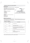
MPU
Version 2.2 revised 19 Mar 2015
User Guide
Multi-Port Unit for the ALC-601
in Revolution XD and WD systems
andor.com
© Andor Technology 2015
MPU
TABLE OF CONTENTS
SECTION 1: INTRODUCTION.............................................................................................................. 12
1.1 INTENDED USE....................................................................................................................... 13
1.2 TECHNICAL SUPPORT........................................................................................................... 14
1.3 DISCLAIMER.......................................................................................................................... 15
1.4 COPYRIGHT AND PROTECTIVE NOTICES............................................................................ 15
1.5 TRADEMARKS AND PATENT INFORMATION........................................................................ 15
SECTION 2: PRODUCT OVERVIEW.................................................................................................... 16
2.1 ANDOR IQ SOFTWARE........................................................................................................... 16
2.2 THE MULTI-PORT UNIT (MPU)............................................................................................... 17
2.2.1
Front View.................................................................................................................. 17
2.2.2
Rear View (MPU Controller)....................................................................................... 18
SECTION 3: SYSTEM OVERVIEW....................................................................................................... 19
3.1 SYSTEM SCHEMATIC............................................................................................................. 19
3.2 SYSTEM CONTROL................................................................................................................ 20
3.2.1
Port Selection ........................................................................................................... 20
3.2.2
Port Status LED Indicators ...................................................................................... 20
3.2.3
Safety Interlock Circuit ............................................................................................ 20
3.2.4
Software Interface...................................................................................................... 21
SECTION 4: SPECIFICATIONS............................................................................................................ 22
4.1 POWER SUPPLY..................................................................................................................... 22
4.2 OPERATING CONDITIONS..................................................................................................... 22
4.3 INTERFACE SPECIFICATIONS............................................................................................... 22
4.3.1
MPU Digital Control................................................................................................... 22
4.3.2
MPU Galvo Cable....................................................................................................... 23
4.4 OPTICAL SPECIFICATIONS.................................................................................................... 23
4.5 MPU MECHANICAL SPECIFICATIONS.................................................................................. 23
4.6 MPU CONTROLLER MECHANICAL SPECIFICATIONS......................................................... 24
4.7 TRANSPORT AND STORAGE................................................................................................. 24
Version 2.2 rev 19 Mar 2015
2
MPU
SECTION 5: INSTALLATION................................................................................................................ 25
5.1 INSTALLATION OF THE MPU................................................................................................. 25
5.1.1
Location and Mounting.............................................................................................. 25
5.1.2Ventilation................................................................................................................... 25
5.1.3Assembly.................................................................................................................... 25
5.1.4
5.2 5.3 Power Connection and Protective Earthing............................................................. 26
INSTALLING THE CABLES..................................................................................................... 26
5.2.1
Power Cabling............................................................................................................ 26
5.2.2
MPU Cabling.............................................................................................................. 26
5.2.3
MPU Galvo Cabling................................................................................................... 27
INSTALLING THE SOFTWARE................................................................................................ 27
SECTION 6: OPERATION.................................................................................................................... 28
6.1 EMERGENCY DISCONNECTION .......................................................................................... 28
6.2 INSTRUCTIONS FOR USE...................................................................................................... 28
6.3 MPU SAFETY SYSTEM OVERVIEW....................................................................................... 28
6.3.1Power Switch ................................................................................................................. 29
6.4 6.3.2
Power-on Indicator .................................................................................................. 29
6.3.3
Lid Interlock Indicator .............................................................................................. 29
6.3.4
Fibre Retaining Shroud ............................................................................................ 29
6.3.5
Fibre Interlock Switch .............................................................................................. 30
6.3.6
Lid Interlock Switch ................................................................................................. 30
INTERLOCK SAFETY SYSTEM OPERATION......................................................................... 30
6.4.1
Conditions for Laser Emission from the ALC........................................................... 31
6.4.2
Conditions for Laser Emission from the MPU.......................................................... 32
Version 2.2 rev 19 Mar 2015
3
MPU
SECTION 7: MAINTENANCE............................................................................................................... 33
7.1 CLEANING AND DECONTAMINATION................................................................................... 33
7.2 REGULAR CHECKS................................................................................................................ 33
7.3 ANNUAL ELECTRICAL SAFETY CHECKS ............................................................................ 33
7.4 FUSE REPLACEMENT............................................................................................................ 33
APPENDIX A: GLOSSARY................................................................................................................... 34
APPENDIX B: OTHER INFORMATION................................................................................................ 35
Version 2.2 rev 19 Mar 2015
4
MPU
Revision History
Version
Released
Description
1.0
Apr 2009
Initial Release
1.1
Apr 2009
Updated format and document structure.
Warning information updated from general to product specific warning.
2.0
Nov 2010
Updated and expanded laser safety section.
2.1
Dec 2010
Updated China office contact details.
Removed terms and conditions of sales link.
2.2
19 Mar 2015
Updated presentation throughout.
Laser safety information updated in line with recent Andor Microscopy
Systems range.
Version 2.2 rev 19 Mar 2015
5
MPU
Safety and Warning Information
PLEASE READ THIS INFORMATION FIRST
1. If the equipment is used in a manner not specified by Andor, the protection provided by the equipment may be
impaired.
2. The RF and Therm connectors on the front panel must be connected before power-on.
3. See Section 6.1, “Emergency Disconnection”.
4. There are no user-serviceable parts inside the product and the enclosure must not be opened. Only authorised
service personnel may service this equipment.
5. This product is powered by the mains and includes mains components. If you open the enclosure, you expose
yourself to electric shock hazards.
6. Protective earth is an integral part of the protection against electric shock in this product. Do not tamper with
any of the earthing measures, e.g. the earth bonding point on the rear panel.
7. Only the correctly specified mains power supply and fuse must be used.
8. A number of screws on the device may have been marked with red paint to prevent tampering. If you adjust
these screws your warranty will be void.
9. The product contains components that are extremely sensitive to static electricity and radiated electromagnetic
fields, and therefore should not be used, or stored, close to EMI/RFI generators, electrostatic field generators,
electromagnetic or radioactive devices, or other similar sources of high energy fields. The types of equipment
that can cause problems are plasma sources, arc welders, radio frequency generators, x-ray instruments, and
pulsed discharge optical sources.
10. Operation of the system close to intense pulsed sources (lasers, xenon strobes, arc lamps, and the like) may
compromise performance, if shielding is inadequate.
11. Your product is a precision scientific instrument containing fragile components. Always handle it with care.
12. Do not wet or spill liquids on the product. Do not store or place liquids on the Cabinet worktop. If spillage
occurs on the product, switch off power immediately, and wipe off with dry, lint-free cloth. If any ingress has
occurred or is suspected, unplug mains cable, do not use, and contact Andor service.
13. The product is only to be used as part of a Revolution XD or WD Microscope System. Users must be authorised
and trained personnel only; otherwise this may result in personal injury, and/ or equipment damage and
impaired system performance.
14. See Section 7.1, “Cleaning and Decontamination”.
15. See Section 5.1.2, “Ventilation”.
16. See the “Manual Handling” section below.
17. To ensure correct and safe operation of this product, please read this manual before use. Keep this user guide
in a safe place for future reference.
Version 2.2 rev 19 Mar 2015
6
MPU
General Safety Symbols
The following are explanations of the safety symbols found on this product:
Caution, risk of electric shock.
Caution, risk of danger.
Caution, consult technical manual before servicing.
Laser Safety and Product Compliance Labels
All relevant safety compliance information is visibly displayed on the ALC-601 as per the International Laser Safety
Standard IEC 60825-1 and the U.S. Laser Product Performance Standard 21 CFR 1040.10.
As the MPU is connected to the ALC-601, which in turn will form part of a unique configuration of components, it
cannot be classified in isolation. Therefore when integrated, it may form part of a system with one of the classifications
described below. A label in the format depicted below will be included for application by the System Integrator following
assessment and classification. The ALC-601 may be configured as part of a larger system that includes multiple Class
3B and Class 4 lasers. A number of separate emission wavelengths can also be available in any one system. In some
very rare occassions another classification label may be used, this will be explained in additional documentation as
appropriate.
Laser products that are safe during use, including long-term direct intrabeam
Class 1
viewing, even when exposure occurs while using optical viewing instruments
(eye loupes or binoculars).
Class 1 also includes high power lasers that are fully enclosed so that no
potentially hazardous radiation is accessible during use (embedded laser
product). Intrabeam viewing of Class 1 laser products which emit visible radiant
energy may still produce dazzling visual effects, particularly in low ambient light.
Class 3B
Class 4
Laser products that are normally hazardous when intrabeam ocular exposure
occurs (i.e. within the NOHD) including accidental short time exposure. Viewing
diffuse reflections is normally safe. Class 3B lasers which approach the AEL
for Class 3B may produce minor skin injuries or even pose a risk of igniting
flammable materials. However, this is only likely if it is a small focused spot.
Note: There exist some theoretical (but rare) viewing conditions where viewing a
diffuse reflection could exceed the MPE. For example for Class 3B lasers having
powers approaching the AEL, lengthy viewing of greater than 10 s of true diffuse
reflections of visible radiation and viewing at distances less than 13 cm between
the diffusing surface and the cornea can exceed the MPE.
Laser products for which intrabeam viewing and skin exposure is hazardous and
were viewing of diffuse reflections may be hazardous. These lasers also often
represent a fire hazard.
Version 2.2 rev 19 Mar 2015
7
MPU
Laser Aperture
Laser Aperture warning labels indicate that during installation laser radiation may be emitted from the optical fibres when
disconnected. When properly installed, no laser radiation will be emitted from these points during use.
LASER APERTURE
LASER APERTURE
Figure 1: Example of Laser aperture warning label
The System Integrator MUST ensure that the final system’s Laser Aperture is suitably labelled e.g. the microscope’s
Objective is identified by a label on the microscope’s stage top. An example is shown below.
The appropriate aperture label is included with the documentation for application by the System Integrator.
Figure 2: Example of Laser emission warning label on microscope
Description of Emitted Radiation from the Laser Product
Parameter
Values
Notes
Wavelengths
400-660 nm
Exact outputs will depend on the integrated laser source, please refer
to it’s Explanatory Label and User Documentation
Beam Divergence
0.3-1.4 NA
Exact divergence will be dependent on the objective in use, please
refer to the microscope’s User Documentation
Maximum Power or
Energy Output
<500 mW
The maximum output power will depend on the integrated laser
source and the configured optical elements but will be significantly
less than 500mW
Pulse Duration
N/A
All recommended laser sources for the Borealis Product are
Continuous Wave output
Pulse Repetition
Rate
N/A
All recommended laser sources for the Borealis Product are
Continuous Wave output
Irregular Pulse
Pattern
N/A
All recommended laser sources for the Borealis Product are
Continuous Wave output
Version 2.2 rev 19 Mar 2015
8
MPU
Description of Emitted Radiation from the Integrated Laser Source
This is dependent on the laser source(s) integrated within the ALC-601. As there are multiple options available from
Andor please refer to the Laser Source’s Explanatory Label and User Documentation for a description of its Emitted
Radiation.
Recommended Responsibilities of a Laser Safety Officer
These include, but are not restricted to, the following; however, national guidelines should also be referred to:
1. Ensuring all personnel requiring access to the product are fully trained in both using the product and the general
use of Class 3B and Class 4 lasers (see below).
2. Ensure users are familiar with the hazardous properties of lasers; namely that laser safety hazards differ from
those of normal light/radiation sources as they are high-intensity, highly collimated beams of electromagnetic
radiation.
3. Ensuring the equipment is used in a controlled area by trained end users in accordance with national guidelines.
4. Ensuring end-users are familiar with the operation of the laser’s key switch control, interlocks, emission LEDs
and other safety features.
5. Ensuring that all interlocks are connected and functioning correctly.
6. We recommend that a copy of IEC 60285-1 is purchased by the laser safety officer for reference.
Guidelines for Safe Operation of Laser Products
1. Read the safety instructions supplied with all equipment in the system.
2. Never look into a laser beam either directly or indirectly.
3. Do not attempt to disassemble the unit housing the lasers or any part of the system. If there is a problem please
contact Andor directly (see SECTION 1.1, “Help and Technical Support”).
4. Restrict and control access to the area(s) where laser(s) are in use to those persons who are trained in the
dangers of lasers and trained on the safety precautions to be observed when working with lasers.
5. Ensure suitable laser warning signs are prominently displayed in the area the system operates.
6. If the system is not in use turn the laser off using the key switch.
7. On a daily basis, or before every use, verify that the laser interlock circuit is working by confirming that the laser
emission indicator on the source turns off when any of the following are done:
•
The microscope binocular eyepieces are in the open position.
•
The articulated transmitted light arm on inverted microscopes is tilted back from the functional vertical
position before using the system.
8. Fluorescent cards should be used to visually locate and indicate the output of invisible wavelengths at all times
9. Additional precautions may need to be implemented as the necessary precautions will be specific to each
system’s installed configuration and typical mode of use. The responsible Laser Safety Officer must assess and
implement the necessary precautions to avoid possible exposure to hazardous radiation during use.
Version 2.2 rev 19 Mar 2015
9
MPU
Classification of an Installed System
The proposed installation scheme of all systems is captured and assessed for all orders received by Andor. To breach
the Class 4 limits for accessible emissions, due to known standard attenuations, the input laser power would have to be
in excess of 5W. We know this configuration is not possible at present and can therefore safely classify the majority of
systems at Factory QC as Class 3B products.
The only case to re-assess the accessible emissions if is the beam path appears to be fully enclosed. The following test
criteria should be applied if a system is felt to be fully enclosed e.g. uses a stage cover and / or environmental enclosure.
Assess if any of the laser emissions are open to Human Access as defined by:
1. ability of the human body to meet laser radiation emitted by the laser product, i.e. radiation that can be
intercepted outside of the protective housing, or
2. ability of a cylindrical probe with a diameter of 100 mm and a length of 100 mm to intercept levels of radiation of
Class 3B and below, or
3. ability of a human hand or arm to intercept levels of radiation above the AEL of Class 3B,
4. also, for levels of radiation within the protective housing that are equivalent to Class 3B or Class 4, ability of any
part of the human body to meet hazardous laser radiation that can be reflected directly by any single introduced
flat surface from the interior of the product through any opening in its protective housing.
The standard Ophir PD-300W sensor and power meter can be used to assess accessible power levels in conjunction
with suitable Safety Glasses and applicable Safe Systems of Work. Any queries should be referred to the Andor Product
Laser Safety Officer for guidance.
If Human Access is not possible then the device should be reclassified as a Class 1 device. This involves the following
steps:
1. Remove all other Explanatory (Classification) Labels EXCEPT those on the Laser Sources (these count as Removable
Laser Sources and need to remain labelled and classified as stand-alone products).
2. Fit a Class 1 Explanatory Label onto a permanently affixed surface which is easily visible before and during operation
of the system.
3. Ensure a Laser Hazard Symbol is clearly visible before and during operation and affix a label if not.
Eye Protection
Eye Protection is not required for the safe use of the device as the only radiation observable (without intentional misuse)
is directionally stable, diffuse and highly divergent from the designated aperture which is static and labelled. Eye
protection must be used by all Installation and service personnel when accessing any radiation during any installation or
service procedure.
If eye protection is deemed desirable by the local Laser Safety Officer, Andor recommends the following products:
•
360 nm – 510 nm – Kentek KXP-4001 Spectacles
•
510 nm – 670 nm – Kentek KRA 6702 Spectacles
Working with Optical Fibres
1. Only service personnel authorized by Andor should remove or inspect fibres.
2. The laser radiation passing through fibres is potentially hazardous, so great care should be taken to avoid
damage that may lead to exposure to this hazardous radiation.
3. The fibre can be easily damaged by bending or general mishandling. Ensure that the minimum curvature is
never exceeded when handling. Recommended minimum bend radius is 30 mm.
4. Optical fibres are prone to damage by bending local to the connector.
5. The coupler is not designed to withstand pulling of the fibre. If the fibre is pulled the system performance could
be compromised or the system may fail.
Version 2.2 rev 19 Mar 2015
10
MPU
Manual Handling
Due to the delicate nature of some of the components within, care must be exercised when handling this product.
Proper manual handling techniques are important when installing the Revolution XD or WD system to ensure that the
integrity of the product is safeguarded and individuals involved are not exposed to unnecessary manual handling risks,
such as:
•
Lifting a load which is too heavy
•
Poor posture or technique during lifting
•
Dropping a load
•
Lifting objects with sharp edges
The MPU is suitable for 1-person installation into an Andor Cabinet.
Version 2.2 rev 19 Mar 2015
11
MPU
INTRODUCTION
SECTION 1: INTRODUCTION
Thank you for purchasing an Andor Multi-Port Unit (MPU).
This manual is aimed at covering the installation, operation and maintenance of the MPU, which enhances the Andor
Revolution XD and WD systems by allowing the laser output of the ALC to be switched to 3 different ports using a fast
galvanometer in approximately 1 ms with good system stability, typically power drift < 2 %/°C over a 24 hour period.
You are now in possession of a unique laser distribution unit, designed for the most challenging microscopy applications.
Before you start to use the product, read this manual thoroughly and follow the instructions given. After reading this
manual, please keep it in a safe place for future quick reference.
The contents of this manual are subject to change without notice. Although every effort has been made to ensure
the accuracy of this manual, errors and/ or inconsistencies may remain. If you note any points that are unclear please
contact your representative.
This product forms part of the Revolution XD and WD systems, and so to use any other equipment with this product,
read the other manuals too. Some of the equipment described in this manual may not be included in the set you have
purchased.
The MPU consists of two major parts: the MPU Head, which is attached to the ALC and contains the optical
components; and the MPU Controller, which controls the galvanometer in the Head.
Figure 3: The Multi-port Unit (MPU) Head attached to an ALC601.
Figure 4: The Multi-Port Unit (MPU) Controller
Version 2.2 rev 19 Mar 2015
12
MPU
INTRODUCTION
The MPU doesn’t operate independently, but requires an ALC and a PCU (see respective user guides). The ALC is
shown in Figure 3 above with the MPU Head attached. The PCU is shown below:
Figure 5: PCUB-110 Precision Control Unit
1.1 Intended Use
This product is intended to be used as part of a Revolution XD or WD microscopy system and should only be used
indoors.
Version 2.2 rev 19 Mar 2015
13
MPU
INTRODUCTION
1.2 Technical Support
If you have any questions regarding the use of this equipment, please contact the representative* from whom your
system was purchased, or:
Europe
USA
Andor Technology
Andor Technology
7 Millennium Way
425 Sullivan Avenue
Springvale Business Park
Suite # 3
Belfast
South Windsor
BT12 7AL
CT 06074
Northern Ireland
USA
Tel. +44 (0) 28 9023 7126
Tel. +1 (860) 290-9211
Fax. +44 (0) 28 9031 0792
Fax. +1 (860) 290-9566
www.andor.com/contact_us/support_request
www.andor.com/contact_us/support_request
Asia-Pacific
China
Andor Technology (Japan)
Andor Technology
4F NE Sarugakucho Building
Room 1213, Building B
2-7-6 Sarugaku-Cho
Luo Ke Time Square
Chiyoda-Ku
No. 103 Huizhongli
Tokyo 101-0064
Chaoyang District
Japan
Beijing,100101 P.R.
Tel. +81-3-3518 6488
China
Fax. +81-3-3518 6489
Tel: +86 (0)10 51294977
Fax. +86(0)10-6445-5401
www.andor.com/contact_us/support_request
www.andor.com/contact_us/support_request
* The latest contact details for your local representative can be found on our website.
Version 2.2 rev 19 Mar 2015
14
MPU
INTRODUCTION
1.3 Disclaimer
THE INFORMATION CONTAINED HEREIN IS PROVIDED “AS IS” WITHOUT WARRANTY, CONDITION OR
REPRESENTATION OF ANY KIND, EITHER EXPRESS, IMPLIED, STATUTORY OR OTHERWISE, INCLUDING BUT NOT
LIMITED TO, ANY WARRANTY OF MERCHANTABILITY, NON-INFRINGEMENT OR FITNESS FOR A PARTICULAR
PURPOSE.
IN NO EVENT SHALL ANDOR BE LIABLE FOR ANY LOSS OR DAMAGE, WHETHER DIRECT, INDIRECT, SPECIAL,
INCIDENTAL, CONSEQUENTIAL OR OTHERWISE HOWSOEVER CAUSED WHETHER ARISING IN CONTRACT TORT
OR OTHERWISE, ARISING OUT OF OR IN CONNECTION WITH THE USE OF THE INFORMATION PROVIDED HEREIN.
1.4 Copyright and protective Notices
The copyright in this document and the associated drawings are the property of Andor Technology and all rights are
reserved. This document and the associated drawings are issued on condition that they are not copied, reprinted or
reproduced, nor their contents disclosed.
The publication of information in this documentation does not imply freedom from any patent or proprietary right of
Andor Technology or any third party.
1.5 Trademarks and Patent Information
Andor and the Andor logo are trademarks of Andor Technology. Andor Technology is an Oxford Instruments company.
All other marks are property of their owners. Borealis includes technology covered by the following patents: US Patent
No. 8,275,226, EP Patent No. 2196839, US Patent No. 8,670,178 and CA Patent No. 2779146.
Changes are periodically made to the product and these will be incorporated into new editions of the manual. New
versions of all Andor manuals will be made available through MyAndor http://my.andor.com/login.aspx. If you do not
have an account please register at http://my.andor.com/Register.aspx.
Version 2.2 rev 19 Mar 2015
15
MPU
PRODUCT OVERVIEW
SECTION 2: PRODUCT OVERVIEW
The Revolution XD and WD Systems provide a framework for Andor’s laser spinning disk, live-cell confocal microscopy
solutions, which combine our award winning iXon Electron Multiplying CCD (EMCCD) camera with the renowned
Yokogawa CSU-X1 and CSU-W1.
The Revolution XD System (shown below) encompasses a range of complementary components, both hardware and
software, that fit seamlessly together creating a complete confocal microscopy solution. A flexible component focus also
allows us to provide key pieces of hardware stand-alone.
Figure 6: Example of a typical Revolution XD Confocal Microscopy System Diagram
See the ALC User Guide and other user guides provided with this manual for more information.
2.1 Andor iQ Software
Andor iQ (Image and Quantify) is our flagship live cell imaging software, designed with flexibility and power in mind. iQ
occupies a central role in our Revolution product range and provides optimised control of Andor’s award winning iXon
EMCCD cameras and automation hardware for a range of bio imaging applications.
Continuous development and improvement ensures that Andor iQ represents a powerful and flexible core for live cell
imaging systems.
See the iQ User Guide supplied with this product for more information.
Version 2.2 rev 19 Mar 2015
16
MPU
PRODUCT OVERVIEW
2.2 The Multi-Port Unit (MPU)
The Multi-Port Unit (MPU) has been designed to attach to the laser exit aperture of the Andor Laser Combiner (ALC). It
allows the laser light output of the ALC to be efficiently coupled into a single mode fibre through one of up to three ports
and thereafter safely directed to one of several possible microscopy system accessories, e.g. confocal scanning unit
(CSU), photo-activation unit (FRAPPA), total internal reflection fluorescence attachment (TIRF). The MPU can be used
with any customer optical accessory designed to accept a single-mode fibre input in the wavelength range 400 to 650
nm. (The fibre output face angle and orientation required will be dependent on the attached accessory.)
The MPU is usually factory-fitted and aligned to an ALC and remains attached to the ALC for shipping to the customer
site. The system has been designed to be robust and should maintain a high fraction of the coupling efficiency
measured in the factory. Due to the extremely tight alignment tolerances required to maintain acceptable fibre power
coupling levels with single-mode fibres and the fact that fibres must be removed and then re-fitted on-site it may be
necessary to perform a re-alignment procedure during installation by an Andor Installation Technician or a trained Andor
Systems distributor.
The MPU has been designed to help ensure that there is no need for special air-conditioning requirements but as the
galvanometer pointing stability is a function of the ambient temperature it is recommended that the ambient laboratory
temperature is regulated if the long-term power output is to be maintained at a reasonable level.
The laser path is totally enclosed so that the user is not exposed to any unnecessary or dangerous levels of laser
radiation. Normally the laser beam is only visible as a highly divergent beam at the sample area of the attached
accessory. During normal operation the various enclosure lids and shrouds must be fitted. If not, the laser safety
interlock operates and laser emission is not possible from the MPU.
2.2.1Front View
MPU Digital
control (x2)
from PCU
Port Status
LED Indicators
Power
Switch
Fibre Output ports
A, B and C (shown
not connected)
MPU Head
MPU Galvo
Cable
Figure 7: MPU Controller and Head highlighted along with the PCU and ALC units.
Version 2.2 rev 19 Mar 2015
17
MPU
PRODUCT OVERVIEW
2.2.2Rear View (MPU Controller)
Mains Inlet
and Fuse
Fan
Exhaust
Vent
Figure 8: Rear Panel of the MPU Controller
Version 2.2 rev 19 Mar 2015
18
MPU
SYSTEM OVERVIEW
SECTION 3: SYSTEM OVERVIEW
3.1 System Schematic
The figure below shows a schematic of the MPU system:
Figure 9: MPU System Schematic
Version 2.2 rev 19 Mar 2015
19
MPU
SYSTEM OVERVIEW
3.2 System Control
The MPU head is attached to the optical output flange of the Andor Laser Combiner (ALC) and the rotation of a
galvanometer mirror allows the laser light output of the ALC to be coupled into one, of up to three, single-mode fibre
outputs.
The angle of the galvanometer mirror located inside the MPU head is controlled by signals generated by the MPU
control unit. The MPU control unit is in turn controlled using two dedicated digital outputs (A0 and A1) supplied by the
Precision Control Unit (PCU). The MPU control unit must also be connected to a mains voltage supply.
3.2.1 Port Selection
The two digital outputs (D0 and D1) control the analog voltage output of the Andor Galvanometer Control PCB. The
analog output of this circuit then feeds into the galvanometer driver PCB and also drives the Port Status LED Indicators.
These two outputs allow the selection of one of the three optical ports (A, B or C) and hence the fibre-optic selected.
The system obeys the following logic:
Port
D0
D1
A 0
1
B 0
0
C 1
0
In the absence of any digital control signals, the MPU will default to the Port B position.
3.2.2 Port Status LED Indicators
The Port Status LED Indicators are directly controlled by the MPU control box circuitry. These green LEDs indicate the
currently selected optical port.
3.2.3 Safety Interlock Circuit
As the MPU Head effectively replaces the standard fibre coupler attached to the front of the ALC chassis, it is important
that any possibility of access and exposure to the ALC laser radiation is minimised.
The MPU fibre retaining shroud and lid are mechanically interfaced to interlock switches and these switches are in
turn connected to and monitored by the ALC interlock safety system. If an attempt is made to remove either of these
components the interlock system will activate and all lasers are immediately turned off and a laser safety shutter will also
close. This ensures that the user will not be exposed to potentially high levels of laser radiation.
The main components and the operation of the safety system are described in more detail in the following sections.
Version 2.2 rev 19 Mar 2015
20
MPU
SYSTEM OVERVIEW
3.2.4 Software Interface
The following illustrates the basic control interface for the MPU. These controls are found on the Acquisition/Auxiliary
devices control window.
Figure 10: Control Interface for MPU
For full details of how to control the MPU option while running protocols please refer to the iQ User Guide.
Version 2.2 rev 19 Mar 2015
21
MPU
SPECIFICATIONS
SECTION 4: SPECIFICATIONS
4.1 Power Supply
This product must be powered via the rear 3-pin IEC C14 connector from an a.c. mains power supply with the following
ratings:
Parameter
Specification
Voltage Range (Europe etc.)
100-240 VAC
Frequency Range
47-63 Hz
Power Rating
15 W
Overvoltage Category
CAT II*
* Note that this is a technical term to say that the product will expect to be plugged into a typical mains socket and experience the typical
transient voltages that appear there.
4.2 Operating Conditions
The product has been designed for the following operating conditions:
Parameter
Specification
Location
Indoor use
Operating Temperature
23°C ± 5°C
Storage Temperature
-30°C to +50°C
Operating Relative Humidity
80% (non-condensing)
Altitude
Up to 2000 m
Pollution Degree
2*
* Note that this is a technical term to say that normally only non-conductive pollution occurs; occasionally, however, a temporary conductivity
caused by condensation must be expected.
•
This product has not been designed to operate correctly in direct sunlight, so it should be avoided.
•
The term “indoor use” also implies that it is not designed to expect water spills.
4.3 Interface Specifications
This section is focused on the electrical specifications of the interfaces, rather than their operation. Information on
operation (including switches) may be found in Section 6, “Operation”.
The following pictures show the front and rear panels of the product with the connectors referred to in this section.
4.3.1MPU Digital Control
This interface is used for control of the MPU from software via the PCU.
Connector Type: BNC Female (50 ohm size)
Signal Type: Digital Input
Electrical Specification: This is a dedicated connection to the PCU and is not designed for other uses.
Version 2.2 rev 19 Mar 2015
22
MPU
SPECIFICATIONS
4.3.2MPU Galvo Cable
This is a dedicated connection between the MPU Controller and the MPU Head for control of the galvanometer and is
not designed for other uses.
4.4 Optical Specifications
Parameter
Specification
Wavelength Range
400 – 650 nm
Power at Output Port
< 500 mW Class 3B*
Output Port
Free-space transmission through FC connector
Single-Mode, polarisation-maintaining armoured fibre assembly.
FC/APC on MPU-side to stop feedback from back-reflections
Optical Fibre
into the laser.
Various output angle and orientation options on output to other
equipment.
Fibre Numerical Aperture
0.11
Polarisation
Parallel to fibre o/p connector keyway
Port Switching Speed
< 1 ms
Fibre Output Power Drift
< 2 %/°C
Long-term Power Stability
<5%
* Output power will vary depending on lasers in system and which ones are switched on at any one time.
4.5 MPU Mechanical Specifications
Parameter
Specification
Enclosure Type
Aluminium block
Width
155 mm
Height
200 mm
Depth
100 mm*
Weight
3.8 kg
Finish
Painted
*Excluding connected cables.
Version 2.2 rev 19 Mar 2015
23
MPU
SPECIFICATIONS
4.6 MPU Controller Mechanical Specifications
Parameter
Enclosure Type
Specification
19” Sub-rack BS EN 60297
Aluminium Construction
Width
480 mm
Height
90 mm (2U)
Depth
315 mm*
Weight
5 kg
Finish
Painted: Housing, Front Panel
Ingress Protection
IP20†
*Excluding connected cables front and rear, but including handles.
†Protection against fingers or other object not greater than 80 mm in length and 12 mm in diameter. Not protected from
harmful entry of various forms of moisture (e.g. dripping, spraying, submersion, etc.)
4.7 Transport and Storage
•
The packaging used for the original delivery should be retained for further use.
•
This product must be shipped in accordance with the international standard ETS 300119 Class 2.1.
•
During shipping the temperature range should not exceed +70°C or fall below -40°C.
•
The crate must be protected from excesses of weather.
•
Shipping crate(s) must be wheeled, wooden and conform to ISPM15 regulations.
•
Relative humidity must not exceed 90% (non-condensing).
Parameter
Specification
Shipped Dimension
650 × 580 × 430 mm (25.6 × 22.83 × 16.93 inches)
Approximate Shipped Weight
10.1 kg
This is for the MPU Controller only. The MPU Head is covered as part of the ALC in the ALC User Guide.
Please note that the product’s cardboard box will be packed along with other boxes inside a larger wooden crate.
Version 2.2 rev 19 Mar 2015
24
MPU
INSTALLATION
SECTION 5: INSTALLATION
This product will usually be supplied as part of a system, and will be installed by Andor Installation Technician or
a trained Andor Systems distributor. The following is only provided to augment this.
5.1 Installation of the MPU
5.1.1Location and Mounting
•
Temperature and humidity must meet the specifications shown in Section 4.2, “Operating Conditions”.
•
Operation vibrations should be reduced as much as possible.
•
Usually the product will be installed in a cabinet. However, if this is not the case, then ensure that the product
is placed on a surface suitable for the weight and size of the product (see Section 4.5, “MPU Head Mechanical
Specifications”, and Section 4.6, “MPU Controller Mechanical Specifications”), and conforming to the other
requirements in this document, e.g. ventilation.
•
If a cabinet is used, it should not be placed tightly against a wall.
•
Power cabling and control cables should be routed to prevent accidents, damage and accidental unplugging.
5.1.2Ventilation
•
The product has an fan exhaust vent on the rear panel, with an intake on the bottom panel.
•
To prevent equipment failure, ensure that there are no obstructions at the inlet or exhaust vents.
•
The product should have a 1U air gap below when installed in a rack, or ensure it stands on its supplied feet if
desk-mounted.
•
Clearance to the rear should be 150 mm.
5.1.3Assembly
The PCU box itself requires no assembly. Cables connections are covered in Section 5.2, “Installation of Cabling”.
Version 2.2 rev 19 Mar 2015
25
MPU
INSTALLATION
5.1.4 Power Connection and Protective Earthing
•
See Section 6.1, “Emergency Disconnection”.
•
Before connection, check that the mains power socket used can provide the power specified in Section 4.1,
“Power Supply”.
•
Always switch off power before connecting/ disconnecting cables from the product.
•
A mains power cable is provided with this product, but ensure that it satisfies local regulations for safety.
•
Mains power is connected via the 3-pin IEC C14 connector on the rear panel of the product.
•
An integral part of protection against electric shock in the case of a fault is the protective earth provided via the
earth conductors in the mains cable. It is therefore vital that the earth system of the building, and in particular
the socket, is constructed properly to provide suitable protection when needed.
•
Do not pull cables by the sheath. Use the connector body.
5.2 Installing the Cables
5.2.1 Power Cabling
See Section 5.1.4, “Power Connection and Protective Earthing”.
5.2.2MPU Cabling
For the Multi-Port Unit (MPU) to operate, the MPU Controller must be connected to the PCU.
1. Connect a 1 m BNC cable (supplied with the MPU Controller) from “Output 0” on the PCU front panel to “Digital
Control 0” on the MPU controller front panel.
2. Connect a 1 m BNC cable (supplied with the MPU Controller) from “Output 1” on the PCU front panel to “Digital
Control 1” on the MPU controller front panel.
Figure 11: MPU to PCU Connection
Version 2.2 rev 19 Mar 2015
26
MPU
INSTALLATION
5.2.3MPU Galvo Cabling
The MPU Galvo Cabling involved accessing the interior of the MPU Controller. Contact Andor technical support if this is
required. (See Section 1.2, “Technical Support”).
5.3 Installing the Software
Refer to your iQ User Guide for details.
Version 2.2 rev 19 Mar 2015
27
MPU
OPERATION
SECTION 6: OPERATION
If the equipment is used in a manner not specified by Andor, the protection provided by the equipment may be
impaired.
6.1 Emergency Disconnection
In case of emergency, the disconnecting device is the mains lead.
This will either be the mains lead connected to the product, or in the case of a cabinet-based system the mains lead
to the cabinet.
SWITCH OFF THE MAINS SOCKET AND REMOVE THE MAINS LEAD FROM THE PRODUCT.
6.2 Instructions for Use
The main operation of this product is as part of the wider Revolution XD system and this is covered in the iQ User
Guide and by the training given by your Andor Installation Technician or trained Andor Systems distributor.
6.3 MPU Safety System Overview
Figure 12: MPU Switch and Indicators
Version 2.2 rev 19 Mar 2015
28
MPU
OPERATION
6.3.1Power Switch
The MPU can only be powered on when mains power is supplied to the MPU Controller and the power switch is turned
on. The switch will illuminate to indicate that the system is powered on (see Figure 10).
6.3.2 Power-on Indicator
The Power ON indicator is built into the Power Switch and will give an indication of a successful power ON condition. It
illuminates (RED) when mains power is supplied to the unit and the Power Switch is in the ON position (see Figure 10).
6.3.3Lid Interlock Indicator
The Lid Interlock Indicator is located on the front indicator panel of the attached ALC (see Figure 10). This indicator will
not only give an indication of the MPU hardware interlock status, but also the ALC interlock status. It illuminates (RED)
when any of the ALC/MPU hardware interlock micro-switches/connectors are in the OPEN state. In the OPEN interlock
state, laser emission is NOT possible from the ALC/MPU.
Figure 13: MPU Head and Interlock Features (note that this shows an image of an early production unit).
6.3.4Fibre Retaining Shroud
The Fibre Retaining Shroud is attached to the top face of the MPU using 2-off, M3 countersunk head machine screws. It
covers the MPU fibre couplers and the corresponding FC style connectors and receptacles (see Figure 14 below). The
connectors cannot be accessed and therefore the fibres cannot be detached from the MPU while the shroud is attached.
The shroud also helps to protect the fibres and couplers from misalignment and accidental damage. This shroud is
fitted after system installation and does not need to be removed during the normal operation of the system.
Version 2.2 rev 19 Mar 2015
29
MPU
OPERATION
6.3.5Fibre Interlock Switch
When the shroud is attached to the MPU the Fibre Interlock Switch is in the CLOSED state. When the shroud is
removed the switch is OPEN and the interlock safety circuit is activated. Access to the fibre optic retaining nut, and
hence fibre removal, can only be achieved when the Fibre Retaining Shroud is removed from the MPU head.
6.3.6Lid Interlock Switch
The Lid Interlock Switch is mounted internally on the middle of the bottom edge of the MPU lid. The reed switch
contacts are of the N/O type. The switch is positioned so that it is only actuated when the lid is located correctly on the
MPU unit. When the lid is removed the switch is OPEN and the ALC/MPU interlock safety circuit is activated. The lid
cannot be removed without de-activating the switch and hence breaking the interlock circuit.
Note that the system is designed so that over-riding the lid or fibre interlock switches will not automatically re-initiate
laser emission – it will also be necessary for the user to perform additional steps to re-initiate laser emission (see iQ User
Guide).
6.4 Interlock Safety System Operation
The MPU interlock system is connected to the ALC interlock safety system. The MPU interlock switches (lid and shroud)
ensure that the user cannot access any laser radiation without activating the ALC interlock safety system.
If any of the interlock switches are disturbed all lasers are immediately turned off and a laser safety shutter also closes
(for a more detailed description of the ALC interlock system please refer to the ALC manual). The iQ software will report
the interlock error as shown similar to that shown below.
Figure 14: Interlock Error in iQ
Version 2.2 rev 19 Mar 2015
30
MPU
OPERATION
To re-initiate laser emission it is first necessary to re-instate (close) the appropriate interlock microswitch(es) and then to
press the RESET button on the SETTINGS tab of the ACQUISITION/AUXILIARY DEVICES window as shown below:
Figure 15: Resetting the Interlock System after Closure of Interlock Switches
In the following sub-sections we define the interlock system to be in the CLOSED state when all of the hardware safety
interlock switches/connectors (see above) are CLOSED. Laser radiation can only pass from the ALC to the MPU when
the interlock system is in the CLOSED state. The electronics logic is designed to minimize any risk caused by faulty
wiring. In these cases the system defaults to a safe operating state:
i.e. an OPEN interlock state → No laser emission possible from ALC/MPU
6.4.1Conditions for Laser Emission from the ALC
Laser radiation can only enter and exit the MPU head when all the conditions for laser emission from the ALC have been
met. Namely:
•
AC Power is applied to the ALC system and the Power Switch (key switch) is ON.
•
All ALC interlocks must be in the CLOSED state.
•
The ALC HEALTH OK pin must be actively set HIGH by the software control interface.
•
The laser/s must be successfully turned on by the software control interface.
•
The appropriate laser line must be selected using the AOTF device
•
The safety shutter must be actively opened using the software control interface.
The appropriate ALC Laser Emission Indicator (see Figure 10) will only illuminate when all these conditions have been
satisfied.
Version 2.2 rev 19 Mar 2015
31
MPU
OPERATION
6.4.2Conditions for Laser Emission from the MPU
Laser radiation will optically couple into the MPU fibre optic cables only when the following conditions have been
satisfied:
•
All of the conditions for laser emission from the ALC unit have been met (see previous).
•
Electrical power is supplied to the MPU control unit and the power switch is on.
•
The MPU interlock switch is closed (i.e. the MPU lid is secured in place).
•
The MPU fibre retaining shroud interlock switch is closed (i.e. the shroud is secured in place).
Version 2.2 rev 19 Mar 2015
32
MPU
MAINTENANCE
SECTION 7: MAINTENANCE
PLEASE NOTE the following:
•
If the equipment is used in a manner not specified by Andor, the protection provided by the equipment
may be impaired.
•
In case of emergency, the disconnecting device is the mains lead. This will either be the mains lead
connected to the product, or in the case of a cabinet-based system the mains lead to the cabinet.
7.1 Cleaning and Decontamination
To clean the product, only use a damp lint-free cloth. Do not wet the connectors. Do not use solvents, cleaning agents,
or aerosols.
7.2 Regular Checks
The state of the product should be checked regularly, esp. the integrity of the enclosure and the mains cable.
Do not use equipment that is damaged.
7.3 Annual Electrical Safety Checks
It is advisable to check the integrity of the insulation and protective earth of the product on an annual basis, e.g. U.K.
PAT testing.
Do not use equipment that is damaged.
7.4 Fuse Replacement
The characteristics of the fuse used in this product are as follows:
Rated Current: 1 A
Rated Voltage: 250 V a.c.
Size: 5 × 20 mm
Type: Time delay, low breaking capacity
The rated voltage could be lowered in North America and countries who use a similar mains supply to 125 V a.c.
The actual fuse used in this product is a Cooper Bussmann S506-1-R or S506-1A.
Version 2.2 rev 19 Mar 2015
33
MPU
GLOSSARY
APPENDIX A: GLOSSARY
ADC
Analogue-to-Digital Converter: Converts an analogue voltage to a digital signal.
ALC
Andor Laser Combiner: The unit at the heart of the Revolution XD that combines laser light from several
internal sources and controls their emission into the microscopy system.
AOTF
Acousto-Optical Tuneable Filter
DAC
Digital-to-Analogue Converter: Converts a digital signal to an analogue voltage.
ESD
Electrostatic Discharge
EMC
Electromagnetic Compatibility
EU
European Union
FRAPPA
Fluorescence Recovery After Photo-bleach (FRAP) and Photo Activation (PA): Imaging protocols in which
a computer-steered laser beam is used to photo-bleach or photo-activate a user-defined region in the
specimen.
IO
Input/ Output: Generic input and output electrical signal connections.
iQ
The PC software used to control the Revolution system.
LED
Light Emitting Diode
MPU
Multi-Port Unit: An optional addition to the ALC that uses fast galvanometer switching to switch the ALC
laser light between multiple ports (usually CSU-X1, FRAPPA and TIRF)..
PCI
Peripheral Component Interconnect: A computer local bus standard for attaching hardware devices in a
computer that can take either the form of integrated circuits fitted onto the motherboard itself, or expansion
cards that fits into slots.
PCU
Precision Control Unit: A Revolution XD unit that provides part of the control of the system including ALC
AOTF control, MPU control, TTL input interface to PC, TTL output interface from PC and analogue piezo
stage control.
MPU
Multi-Port Unit: A special head using galvanometers to direct the laser light from an ALC through to multiple
ports, together with its control box.
SMA
Sub-Miniature version A: Coaxial RF connectors with a screw type coupling mechanism, and available in 50
Ω impedance only.
SMB
Sub-Miniature version B: Coaxial RF connectors with a screw type coupling mechanism, smaller than an
SMA connector, and available in 50 Ω and 75 Ω impedances.
SMC
Sub-Miniature version C: Coaxial RF connectors with a screw type coupling mechanism, smaller than both
SMA and SMB connectors, and available in 50 Ω and 75 Ω impedances.
TIRF
Total Internal Reflection Fluorescence: The electromagnetic field of the Totally- Internally Reflected light
extends into the sample beyond the interface by 100-200 nm into the medium of lower refractive index, so
that only a very thin section of the specimen undergoes fluorescence excitation.
USB
Universal Serial Bus: A serial bus standard to connect devices to a host computer.
Version 2.2 rev 19 Mar 2015
34
MPU
OTHER INFORMATION
APPENDIX B: OTHER INFORMATION
Terms and Conditions of Sale and Warranty Information
The terms and conditions of sale, including warranty conditions, will have been made available during the ordering
process. The current version may be viewed at: http://www.andor.com/pdfs/literature/Andor_Standard_Warranty.pdf
Waste Electronic and Electrical Equipment Regulations 2006 (WEEE)
The company’s statement on the disposal of WEEE can be found in the Terms and Conditions
Version 2.2 rev 19 Mar 2015
35