1
High Performance Image Control System, Version 6.4
HiPic
User Manual
LEGAL TERMS
Please read this license carefully before installing or using the software. By using the software, you are agreeing to be
bound by the terms of this license. If you do not agree to the terms of this license, do not install or use the software and
erase it from your computer.
COPYRIGHT
The HPD-TA software (herein called the Software) and all accompanying documentation (herein called the Documentation) are
copyrighted by Hamamatsu Photonics Deutschland GmbH (herein abbreviated as HPD) with all rights reserved. It is illegal to copy
(except as granted under section "License Agreement" below), duplicate, sell, or otherwise distribute the Software or the Documentation or any parts of them without written permission from HPD.
Any attempts to "reverse-engineer", "disassemble", "re-source" the Software or to modify the Software in any way are violations of
HPD's copyright and may be legally prosecuted.
LICENSE AGREEMENT
HPD gives you the permission to copy the software for your own use as long as it is absolutely necessary for using the Software for
its intended purpose. This includes your right of loading the Software into the computer's memory and making copies of the installation disks for the purpose of backup. You may also run multiple copies of the Software on several computers for the purpose of data
inspection and analysis. Under no circumstances, however, are you allowed to use the Software to drive data acquisition hardware
on more than one computer simultaneously at any given time.
WARRANTY
All efforts have been made to make the Software and the Documentation as accurate and free of "bugs" as possible. However, HPD
makes no warranties, express or implied, and specifically disclaims any warranty of merchantability or fitness for a particular purpose. In no event is HPD liable for direct, indirect or consequential damages of product or property, personal
damage, inconvenience, loss of time, data or profits, which may result from the use of the Software, even if advised the
possibility thereof. The entire risk as to the results and performance of the Software is assumed by the purchaser.
Specifically, where life or health is involved, results obtained with the Software should be examined carefully before any conclusions
are made. The Software and the Documentation are not designed and tested intending to ensure a level of reliability suitable for use
in diagnosis and treatment of humans.
TRADEMARKS
Product names and company names mentioned in the Software or the Documentation are trademarks or trade names of their respective holders.
UPDATES
Update conditions may vary depending on where you purchased this product. Please contact your local Hamamatsu subsidiary or
retailer to obtain information about the update conditions valid for you.
HPD is committed to a policy of customer satisfaction and product reliability. If you find any errors, "bugs" or other inconveniences in
the Software or the Documentation, please inform HPD or your local retailer so that countermeasures are possible with the next
update.
Copyright by Hamamatsu Photonics Deutschland GmbH, D-82211 Herrsching, 2002
ver 6.4/01
Content
Introduction
6
General ............................................................................................................................... 6
Update Information............................................................................................................. 7
What is New in HiPic 3.0? ................................................................................... 7
What is New in HiPic 3.1? ................................................................................... 7
What is New in HiPic 3.2? ................................................................................... 8
What is New in HiPic 4.0? ................................................................................... 8
What is New in HiPic 4.1 and higher? ................................................................. 8
What is New in HiPic 4.2? ................................................................................. 10
What is New in HiPic 5.0? ................................................................................. 10
What is New in HiPic 5.02? ............................................................................... 11
What is New in HiPic 5.1? ................................................................................. 11
What is New in HiPic 6.0? ................................................................................. 11
What is New in HiPic 6.1? ................................................................................. 11
What is New in HiPic 6.2? ................................................................................. 12
What is New in HiPic 6.3? ................................................................................. 12
What is New in HiPic 6.4? ................................................................................. 12
Set-up and Installation
13
Overview .......................................................................................................................... 13
Hardware Set-up and Configuration................................................................................. 13
Software Installation......................................................................................................... 14
Camera Configuration Files *.cnf ...................................................................... 17
Hardware Installation ....................................................................................................... 18
Starting the program
20
Start................................................................................................................................... 20
Initialisation ...................................................................................................................... 21
CCD camera access ............................................................................................ 21
Frame Grabber.................................................................................................... 21
Camera Type ...................................................................................................... 21
Configuration File .............................................................................................. 22
Getting Started
22
Overview .......................................................................................................................... 22
Starting with the C4742-95 Camera ................................................................................. 22
Starting with the C4880 Camera....................................................................................... 24
Starting with an Analog Video Camera............................................................................ 27
Command Overview
30
Basic operations
32
Overview .......................................................................................................................... 32
LUT Tool.......................................................................................................................... 32
Image Display................................................................................................................... 35
High Performance Image Control System, HiPic
Introduction • i
Selecting Regions of Interest (ROIs) ................................................................................ 37
QuickProfile...................................................................................................................... 39
General Comments on Image Acquisition ........................................................................ 40
Camera and Frame-buffer................................................................................... 40
How Areas are Transferred from Camera to Frame-buffer ................................ 40
Considering 8, 10, 12, 14, 16 and 32 bit Images ................................................ 41
Error Handling .................................................................................................................. 42
Application Control Window
43
Application Control Window............................................................................................ 43
Menu Bar ............................................................................................................ 43
Tool Bar.............................................................................................................. 44
File Menu
46
Overview........................................................................................................................... 46
Save As .. and Save ROI As .. ......................................................................................... 46
File Comment ..................................................................................................... 50
Open.................................................................................................................................. 50
File info .............................................................................................................. 50
Print... ............................................................................................................................... 51
Image Status...................................................................................................................... 51
Exit.................................................................................................................................... 51
Setup menu
52
Overview........................................................................................................................... 52
C4742-95 Set-up............................................................................................................... 52
C4742-95-12HR Set-up .................................................................................................... 55
C4880 and C7190-10 Set-Up............................................................................................ 57
Analog Contrast Enhancement and Shading Control ......................................... 58
Cooler and Temperature Control........................................................................ 58
Camera Info ........................................................................................................ 59
C4880-8x Set-Up .............................................................................................................. 59
Analog Contrast Enhancement ........................................................................... 59
Camera Info ........................................................................................................ 60
C4742-98 Set-up............................................................................................................... 60
C7300-10 Set-up............................................................................................................... 61
C8000-10 Set-up............................................................................................................... 64
C8000-20 Set-up............................................................................................................... 65
C7921/C7942/C7943 Set-up............................................................................................. 66
Analog Camera Set-up (IC-PCI with AM-VS or PCVision only).................................... 67
Scaling Set-up................................................................................................................... 68
Introduction to Scaling ....................................................................................... 69
Linear and Table Scaling.................................................................................... 70
System, Image and Profile Scaling..................................................................... 70
Scaling Set-up: Using Different Scaling Methods.............................................. 71
Scaling Method: No Scaling............................................................................... 72
Scaling Method: Square Scaling......................................................................... 72
Scaling Method: Free Scaling............................................................................. 73
Scaling File Editor ............................................................................................................ 74
Options.............................................................................................................................. 77
Overview ............................................................................................................ 77
Section General .................................................................................................. 77
Section Acquisition ............................................................................................ 78
Section Images.................................................................................................... 79
Section Sequence................................................................................................ 81
Acquisition Menu
ii • Introduction
83
High Performance Image Control System, HiPic
Overview .......................................................................................................................... 83
General ............................................................................................................................. 83
Basics of the Photon Counting Mode ............................................................................... 85
Conditions for Photon Counting Mode .............................................................. 86
Methods to Perform Photon Counting: Slice, Peak Detection, Gravity ............. 86
Photon Counting Setup....................................................................................... 87
Photon Counting Condition................................................................................ 88
Dynamic Photon Counting (time resolved 2-D photon counting)...................... 88
C4742-95 (ORCA) and ORCA HR .................................................................................. 90
Live Mode .......................................................................................................... 90
Acquire Mode..................................................................................................... 91
Analog Integration Mode ................................................................................... 92
Photon Counting Mode ...................................................................................... 92
C4742-98 (ORCA II)........................................................................................................ 93
Live Mode .......................................................................................................... 93
Acquire Mode..................................................................................................... 96
Analog Integration Mode ................................................................................... 97
Photon Counting Mode ...................................................................................... 97
C7300 ............................................................................................................................... 99
Live Mode .......................................................................................................... 99
Acquire Mode................................................................................................... 100
Analog Integration............................................................................................ 101
Photon Counting............................................................................................... 102
C4880 (except C4880-80) .............................................................................................. 103
Live Mode with C4880 and C7190-10 Cameras .............................................. 103
Acquire Mode for Standard C4880 and C7190-10 Cameras........................... 107
Analog Integration Mode with C4880 and C7190-10 Camera....................... 107
Photon Counting Mode with C4880 and C7190-10 Camera........................... 108
C4880-80 ........................................................................................................................ 110
Live Mode ........................................................................................................ 110
Acquire Mode................................................................................................... 111
Analog Integration Mode ................................................................................. 112
Photon Counting............................................................................................... 112
C8000 ............................................................................................................................. 113
Live Mode with C8000-10 Camera.................................................................. 113
Acquire Mode with C8000-10 Camera ............................................................ 114
Live Mode with C8000-20 Camera.................................................................. 115
Acquire Mode with C8000-20 Camera ............................................................ 116
C7921, C7942 and C7943 .............................................................................................. 117
Live Mode ........................................................................................................ 117
Acquire mode ................................................................................................... 118
Analog Integration............................................................................................ 119
Analog Video Cameras................................................................................................... 119
Live Mode ........................................................................................................ 119
Acquire mode ................................................................................................... 121
Analog Integration............................................................................................ 121
Photon Counting Mode .................................................................................... 122
Freeze ............................................................................................................................. 123
Changing the Acquisition Mode..................................................................................... 123
Clear Image..................................................................................................................... 123
Sequence......................................................................................................................... 124
Setting the acquisition parameters.................................................................... 124
Image Sequences .............................................................................................. 125
Profile sequences.............................................................................................. 130
Processing sequences ....................................................................................... 130
Averaging ......................................................................................................... 131
Corrections
High Performance Image Control System, HiPic
133
Introduction • iii
Overview......................................................................................................................... 133
Background Subtraction ................................................................................................. 133
Shading Correction ......................................................................................................... 133
Defect Pixel Correction Setup ........................................................................................ 134
Correction setup................................................................................................ 134
Enabling bad pixel correction........................................................................... 136
Correction Set-up............................................................................................................ 137
Background Subtraction ................................................................................... 138
Background Subtraction from Camera ............................................................. 138
Background Subtraction from File ................................................................... 139
Details About Background Subtraction............................................................ 140
Constant............................................................................................................ 140
Get real-time backsub data from camera .......................................................... 140
Shading Correction........................................................................................... 140
Get a Shading Reference Image ....................................................................... 141
Declare an Image as Shading Reference Image................................................ 141
Algorithm of Shading Correction ..................................................................... 141
Analysis Menu
143
Overview......................................................................................................................... 143
Profile ............................................................................................................................. 143
General Information on Profile Analysis.......................................................... 143
The Profile Control........................................................................................... 144
Acquiring Profiles ............................................................................................ 146
Displaying Profiles ........................................................................................... 147
Profile Scaling .................................................................................................. 149
Profile Analysis ................................................................................................ 150
Displaying Profile Data .................................................................................... 152
Using the Clipboard and DDE Links................................................................ 153
Histogram Analysis......................................................................................................... 153
3D Data........................................................................................................................... 154
Extract 3D Data from an Image........................................................................ 154
Using the Clipboard or a 3D Data DDE Link .................................................. 155
Display Menu
156
Overview......................................................................................................................... 156
LUT (Look up Table) ..................................................................................................... 156
Processing menu
158
Overview......................................................................................................................... 158
Map Values by LUT ....................................................................................................... 158
Arithmetic ....................................................................................................................... 158
User Function.................................................................................................................. 160
Superimpose ................................................................................................................... 163
Technical Explanation of Superimpose ............................................................ 163
The Superimpose Control................................................................................. 164
Info Menu
166
Overview......................................................................................................................... 166
RS232 ............................................................................................................................. 166
About .............................................................................................................................. 167
Appendix
169
Appendix A: Files Used in HiPic ................................................................................... 169
Appendix B: Image File Format ..................................................................................... 169
iv • Introduction
High Performance Image Control System, HiPic
Appendix C: Profile File Format .................................................................................... 170
Appendix D: Status String Format ................................................................................. 171
Appendix E: Scaling File Format ................................................................................... 179
Appendix F: DPC File Format........................................................................................ 179
Appendix H: Cameras and Peripheral systems supported .............................................. 180
Appendix I: UserFunction .............................................................................................. 180
Glossary
184
Index
187
High Performance Image Control System, HiPic
Introduction • v
Introduction
General
HiPic is an image processing software for high performance CCD cameras. It is
mainly designed for use in combination with the ORCA (C4742-9x b/w) digital
cameras and the C4880 cooled CCD cameras, but it can also be used with standard analog video cameras (CCIR or EIA standard)and CMOS X-ray flat panel
sensors.
HiPic was designed to offer a user-friendly operation system for these cameras
as well as all basic image processing functions needed for routine work.
You may use this manual for two reasons:
•
To get started with the digital image processing system
•
To get detailed information about complex operation methods and procedures. Since HiPic is a "look and feel" program, you may not need this
manual for your daily work. However there are several functions which
may not be understood easily by just using the program. We have put priority to explain such items in this manual.
You should read several parts of this manual before you start.
We recommend to read the chapter "Set-up and Installation" on page 13 first.
Then you should read the chapters "Starting the program" on page 20, "Basic
operations" on page 32 and "Setup menu" on page 52.
The chapter "Getting started" will show you step by step how to acquire your
first images, the chapter "Starting the Program" tells you in more detail, how to
start-up the program and gives you an overview about the main commands. In
the chapter "Basic Operations" you will find important basic information about
the program", in the chapter "Setup menu" a description about commands for
system set-up is given. You should be familiar to these commands before you
use the system extensively and make the set-up according to your system configuration.
If your system was installed by Hamamatsu already, you may skip the chapter
"Set-up and Installation".
Later on you may use the manual to understand and use special functions.
We assume that you are already familiar to Microsoft Windows/Windows NT
and its standard operations. If you use Windows/Windows NT for the first time,
please study its functions first.
Before you read this manual you should check your actual hardware system
configuration. Since several HiPic functions are different depending on the actual camera or frame grabber, it is important to know, which system you use.
6 • Introduction
High Performance Image Control System, HiPic
Note: C4742-95 is the Hamamatsu type number for ORCA , C4742-95ER is
the type number for ORCA ER and C4742-98 is the Hamamatsu type number for ORCA II. In this manual only type numbers are used for camera
identification.
Update Information
If you update your HiPic software from an older version to the actual version,
you may want to know, which functions have been added compared to your old
version. Following chapter describes these changes. If you use HiPic for the
first time, you do not need to read this information.
What is New in HiPic 3.0?
HiPic 3.0 is a completely updated program version which has a lot of new and
useful features. It can read all files created by previous versions and is fully
compatible to older versions. The major changes are:
•
A new and sophisticated scaling scheme is introduced
•
Completely revised profile functions including separate profile display
window, auto update, detailed analysis, faster profile generation, display of
the profile areas, print function, profile save with ASCII pairs (X,Y) and
real-time profile
•
A new hardware based program lock (a GAL has to be inserted in the AFG
board)
•
A new shading correction function
•
Automatic background subtraction and automatic shading correction
•
Improved scroll function
•
Unary and binary arithmetic operations
•
New TIGA extension code for background subtraction, shading correction
and profile generation, speeding up these operations considerably
•
The GAOI selection box displays scaled information now
•
An improved command interface for the C4880 cameras
•
A new 16 bit mode which allows integration into the frame-buffer
What is New in HiPic 3.1?
HiPic 3.1 is a new subversion and includes following new features and improved functions:
•
Video gain and offset adjustment for the analog video signal.
•
A new acquisition mode for analog video cameras called SyncLive mode,
which allows to synchronize the acquisition to external events (e.g. Laser
with low repetition rate). This mode is using the trigger input of the AFG
board, no additional hardware is necessary.
•
It allows to save profiles within the cycle mode.
•
Display of the profile data within a text box including scaling information.
•
Possibility to establish DDE links which can transfer profile data to other
programs (e.g. Microsoft Word for Windows, Microsoft Excel etc.) for
quick and customised data display and analysis.
High Performance Image Control System, HiPic
Introduction • 7
•
Display 3D Data.
•
Possibility to establish a DDE link which can transfer 3D data to other programs (e.g. Microsoft Word for Windows, Microsoft Excel etc.) for quick
and customised data display and analysis.
•
Possibility to specify the COM port when using the C4880 camera.
•
Non-linear scaling data is now kept within the image file. There is no
longer the need to keep separate scaling files.
•
Modified profile file format which allows more easy data exchange with
other programs.
•
An intelligent error handler which writes a detailed error report if an error
occurs. This allows to debug errors more quickly than before and assures
better program reliability.
What is New in HiPic 3.2?
HiPic 3.2 is a new subversion and contains several new features and improved
functions:
•
A new, more easy to use set-up program.
•
Ability to save images in 16 bit TIFF format.
•
Ability to switch between analog camera input channels.
•
A real-time background subtraction function for the C4880 camera.
•
User DLL calls within the HiPic. The user can now control external hardware, the frame grabber, the camera and analyse data while HiPic is running. These DLL calls are done from various points within HiPic before or
after acquisition and within a cycle.
•
Printout of file information.
What is New in HiPic 4.0?
HiPic 4.0 is a new main version and includes the following new features and
improvements:
•
A new and powerful PCI-based state of the art frame grabber is supported.
It is the IC-PCI from Imaging Technology (ITI).
•
Support of 14 and 16 bit data acquisition.
•
Image display on the VGA monitor.
•
Display of more than one image at a time.
•
Support of a mode where images can be viewed analysed and saved without
frame grabber.
•
Most functions perform considerably faster than with older versions.
•
Fully compatible to image and profile files of older program versions.
•
A new hardware lock is used. AFG board with the protection GAL still
works.
What is New in HiPic 4.1 and higher?
HiPic 4.1 is a new sub-version and contains the following new features and improvements:
8 • Introduction
High Performance Image Control System, HiPic
•
A sequence mode for the C4880 for fast acquisition of sequences is available a. This works as fast as the camera can output images and is only limited by the size of RAM in your computer.
•
An acquisition module (the AM-VS) to acquire analog video images for the
IC-PCI is supported. With a special small hardware also on-chip integration
for the Hamamatsu C3077 and C5405 cameras is supported.
•
Support of the C4880-81/82 camera models.
•
The superimpose and the photon counting function which was only available in the special HiPic/EM program is now available in the standard
HiPic. For this reason the HiPic/EM will be discontinued now.
In addition to these features the sub-version HiPic 4.1.2 includes the following new
features and improvements:
•
Improved support of the C4880-81/82 cameras.
•
Support of the C4742-95 camera
•
Support of the C4880-96/97 cameras
•
Image size can be 1280 x 1024 pixels now (Acquisition of this size is only
possible with the 4M version of the IC-PCI)
•
Now scaling tables can have a length of 1280 floating point values (old type
scaling files can still be used).
•
The sequence mode also works if the vertical blank (VB) is very short.
Older versions of the program have required a VB of at least several milliseconds duration.
•
Several bug fixes of the previous version
In addition to these features the sub-version HiPic 4.1.3 includes the following new
features and improvements:
•
•
In the cycle mode images can be saved in IMG, DataToTiff and DisplayToTiff Format.
•
A new improved photon counting algorithm for the video acquisition. Photon counting can now be done in real time (provided the computer is fast
enough). There are three methods for photon counting now: centre of gravity, peak detection and slice mode.
•
If no license is available (no hardware lock or GAL) the system starts in
demo mode. Then the user has the possibility to select between acquisition
and processing mode. In acquisition mode the user can acquire images (including sequence function if available for the camera/frame grabber) but
cannot save data (images or profiles). In processing mode the user can save
and load data but cannot do acquisitions.
•
The shutter camera C5987 (C4880-92) and the sub-nanosecond shutter
camera C6918-05 (C4880-93) is now supported
In addition to these features the sub-version HiPic 4.1.4 contains the following new
features and improvements:
•
•
The 4742-95 camera can now be operated in Live, Acquire, Analog Integration and Photon Counting mode.
•
The performance of Photon Counting and Analog Integration have been enhanced. For analog video cameras these modes can be performed in realtime.
High Performance Image Control System, HiPic
Introduction • 9
•
TIFF files have now scaling information. It is possible to save sequences in
TIFF format. The FITS format is supported.
•
New functions for ROI handling have been implemented. It is now possible
to move and resize ROIs.
•
It is now possible to save just data within a ROI in sequence mode.
What is New in HiPic 4.2?
HiPic 4.2 is a new sub-version and contains the following new features and improvements:
•
The Realtime Profile function is replaced by a more versatile function
called QuickProfile.
•
The sequence function is now also available for standard analog video cameras
•
Images can be saved in ASCII format
•
Sequence function has been improved. Now cyclic acquisition and replay is
possible. It is possible to display images during sequence acquisition.
What is New in HiPic 5.0?
HiPic 5.0 is a new main version and includes the following new features and
improvements:
•
eThe program is now true 32 bit code and runs under Windows NT
as well as Windows 95
•
It is now a MDI (Multiple document interface) application
•
The image save and image load functions have been completely
revised to allow a more user friendly operation
•
The analog integration function has been optimised to work accurately even with critical short integration times
•
The look and feel of all image acquisition modes has been improved (including tool-tips for online information)
•
A new option called “After-trigger integration for analog video
camera configurations has been introduced
Following features are not any more available since this version:
10 • Introduction
•
The frame grabber AFG is not supported any more
•
The camera C4742-01 is not supported any more
•
The program does not run under Windows 3.1 any more
•
Camera On-chip integration with standard analog video cameras is
not supported any more
High Performance Image Control System, HiPic
What is New in HiPic 5.02?
HiPic 5.02 is a new subversion and includes the following new features and improvements:
•
Sequenceand Cycle mode have been revised and unified in order to
get a more versatile functionality. Processing speed has been improved.
•
A new photon counting function for time resolved 2-D photon
counting called Dynamic Photon Counting has been implemented.
What is New in HiPic 5.1?
HiPic 5.1 is a new subversion and includes the following new features and improvements:
•
A real-time background image subtraction function in Live mode
has been added.
•
Image display speed in Live mode has been improved.
•
Non-linear contrast enhancement functions have been added.
What is New in HiPic 6.0?
HiPic 6.0 is a new main version and includes the following new features and
improvements:
•
The code is rearranged and grouped into objects. This has two consequences:
A) Testing, bug-fixing and maintenance is easier.
B) The program can be remotely controlled by another application.
•
Control of C4742-98 and C7300-10 are now available
•
There is a new menu command "Save ROI As" which saves only
the ROI. The command Save As always saves the full image without prompting the user.
•
The options are grouped more logical according to the objects
•
A new error handler is installed which gives more precise information about the calling list and the latest executed commands/events
before the occurrence of the error.
•
New timeout behaviour in many cases especially in the case of
triggered acquisition.
•
What is New in HiPic 6.1?
HiPic 6.1 is a new sub-version and includes the following new features and improvements:
•
Cooled CCD cameras with up to 16 bit A/D converter are supported. .
•
A 32-bit file format is used. Previous versions can not read this file
format.
High Performance Image Control System, HiPic
Introduction • 11
•
New frame grabber are supported: PCDIG for digital cameras and
PCVision for analog cameras.
•
New cameras are supported: ORCA ER, C8000 series, C7190 series.
What is New in HiPic 6.2?
HiPic 6.2 is a new sub-version and includes the following new features and improvements:
•
C8484, ORCA HR and X-ray Flat Panel sensors C7943/C7942 are
supported .
What is New in HiPic 6.3?
HiPic 6.3 is a new sub-version and includes the following new features and improvements:
•
Cameras with FireWire (IEEE1394) interface are supported using
the Hamamatsu DCAM driver concept.
•
Defect sensor pixel correction has been implemented.
•
Support of X-ray flat panel sensors has been extended.
What is New in HiPic 6.4?
HiPic 6.4 is a new sub-version and includes the following new features and improvements:
12 • Introduction
•
The frame grabber types National Instruments PCI1422 and
PCI1424 are supported
•
A modified setup procedure has been introduced
High Performance Image Control System, HiPic
Set-up and Installation
Overview
This chapter describes the hardware configuration, set-up and software installation of the HiPic system. If your system was already pre-installed by Hamamatsu you do not need to read his chapter.
Note: Please install the software at first. Install the hardware in a
second step.
Hardware Set-up and Configuration
The HiPic requires the following system components:
•
Cameras with RS422 or RS 644 interface:
Frame grabber:
IC-PCI+AM-DIG, or PCDig, or National Instruments PCI 1422 / PCI
1424
•
Cameras with IEEE1394 interface:
IEEE1394 adapter
•
Analog cameras
Frame grabber:
IC-PCI+AM-VS or PC-Vision
•
Computer environment:
An industry standard PC (at least with Pentium processor) with at least 32
MB RAM (64 MB recommended), a VGA board (PCI recommended),
one free serial port (for the C4880, C4742-98 and C4742-95 camera), one
PCI slot, Windows´98, Windows ME, Windows NT, Windows XP or
Windows 2000 is required.
•
HiPic software
•
•
Camera:
A Hamamatsu digital camera C4742-95, -98 (black and white version),
C4880, C7190, C7300-10, C8000, X-ray Flat panel sensor or a camera
with standard analog video signal (e.g. Hamamatsu C3077).
Accessories (if C4880 is used):
Depending on the C4880 camera type, a water cooler and vacuum pump
may be necessary.
High Performance Image Control System, HiPic
Set-up and Installation • 13
Software Installation
HiPic software is delivered on a CD.
Note: You should install the frame grabber board (or IEEE1394 adapter) into
your computer after software installation.
Start Windows´98SE, Windows ME, WindowsNT 4.0 SP6 ,Windows 2000 or
Windows XP.
Note: Cameras with IEEE1394 interface are not supported under Windows NT.
Insert the CD into you CD drive. The installation program will normally be
started automatically by a “autostart” routine.
If it does not run automatically, you have to select "Run" from the "Start" menu
and type D:\SETUP, then click "OK" (assuming that your CD drive has the
name D).
The set-up program will start.
Follow the instructions displayed on the screen.
-
Make sure that elder versions of the program are uninstalled before the new
version is installed.
-
Please collect information about the camera type and interface type (grabber, IEEE1394 etc) before you start the installation. Press Help on selecting cameras... to get some help about camera and interface selections.
Start with the software installation (Press “Install the HiPic”)
During installation you will be asked if you want to do a typical, compact or
custom installation.
14 • Set-up and Installation
High Performance Image Control System, HiPic
Setup type selection dialogue
We recommend to select “typical” installation. All necessary program components will be installed including hardware drivers.
If you choose “compact”, only the program components necessary to run the
core program will be installed. Choose this option only if you want to use the
program just for image analysis, not for image acquisition.
If you choose “custom” a dialogue box will be opened where you can choose the
program components which you want to install individually. Choose this only if
you are familiar with the program structure. The system may not work properly
if you do not install the proper components.
By default the program will be installed in the directory c:\programs\HiPic 640.
If you have installed a previous version of the software a warning message will
appear where you are asked if you want to overwrite the existing configuration
file or not. Unless you have changed your hardware configuration you should
use the existing file.
Depending on the camera model and camera interface type you have to decide
which setup type you want to use.
Select DCamAPI modules for configurations supported by a Hamamatsu
DCAM driver (e.g. cameras connected by IEEE 1394 interface).
Select Internal drivers for cameras not supported by DCAM.
Please ask your camera supplier if you are not sure which setup type you should
use.
High Performance Image Control System, HiPic
Set-up and Installation • 15
Setup type selection dialogue
If you have chosen the Internal drivers setup type you will be asked which
camera and frame grabber you want to use in the camera selection dialogue and
the frame grabber in the frame grabber selection dialogue. These dialogues will
show up only if you have selected No in the previous dialogue.
Camera selection dialogue
Please select the frame grabber which you intend to use in the next dialogue.
Frame grabber selection dialogue for digital cameras
16 • Set-up and Installation
High Performance Image Control System, HiPic
Frame grabber selection dialogue for cameras with analog signal output
At the end of the installation you will be advised to install additional program
components such as a hardware lock driver or a frame grabber driver and you
will be asked if you want to reboot your computer. If you decide to do it later,
you have to make sure that you do not start the program before you have restarted the computer.
Continue with the next installation step shown at the setup launcher.
Typically this is the installation of the hardware lock driver.
The final installation step is the installation of a hardware interface driver.
You have to choose 1 out of the 4 alternative drivers (ITEX, IFC, NI-IMAQ or
DCAM) shown in the setup launcher dialog. Please choose the proper driver for
your actual installation.
After completion of the installation you have to re-boot your system.
We recommend to read some parts of this manual before you start to work with
HiPic for the first time. In order to acquire the first images, proceed with the
chapters "Starting the program on page 20 and.
The following chapter gives you additional information. However, you need to
read it only in case you find some problems with your system.
Camera Configuration Files *.cnf
During installation the program will already load and activate the configuration
file which will fit for your configuration. However, if you want to change to another camera later, you should also change the configuration file (*.cnf). Please
insert the correct name of the configuration file in the start-up window (see also
High Performance Image Control System, HiPic
Set-up and Installation • 17
"Starting the program" on page 20). Following configuration files are currently
available:
Configuration file..
...with frame
grabber...
... for the cameras
DIGITAL.CNF
IC-PCI+AM DIG
All digital cameras like C4742
(ORCA) series and C4880 series
CCIR.CNF
IC-PCI+AM VS
For analog video cameras with
CCIR standard
EIA.CNF
IC-PCI+AM VS
For analog video cameras with
EIA standard
PCVSCCIR.CNF
PCVision
For analog video cameras with
CCIR standard
PCVS_EIA640.CNF PCVision
For analog video cameras with
EIA standard
C8000-20.CNF
IC-PCI+AM DIG
C8000-20
PCDig.txt
PCDig
All digital cameras
The National Instruments frame grabber PCI 1422 and PCI 1424 do not require
such file.
Hardware Installation
Do the following steps to install the hardware of your HiPic system:
Step 1: Install the frame grabber or IEEE1394 interface
board in your computer.
Install the frame grabber board in a free PCI slot of your computer. Following
frame grabber are supported: IC-PCI with AM-DIG and AM-VS module, PCVision, PCDig, NI PCI 1422, NI PCI 1424.
If you use a camera with IEEE1394 (FireWire) interface, an interface adapter is
needed instead of a frame grabber board.
Step 2: Install the software protection.
In order to work with HiPic you have to install a hardware lock.
If this is not installed, HiPic works in demonstration mode only.
Connect the hardware lock (this is a 25 pin connector labelled with the name of
the program or a USB stick type ) to the parallel port (LPT1) resp. a USB port of
your computer. The hardware lock is delivered with the HiPic program disk.
Step 3: Make the cable connections
•
Connect all cables of your computer (AC cable, keyboard, mouse, monitor
etc.)
•
Connect all AC line cables of your other devices.
•
Connect the camera to the input connector of the frame gabber board.
If you use a Hamamatsu digital camera:
•
18 • Set-up and Installation
Connect the camera head to the camera controller.
High Performance Image Control System, HiPic
•
Connect the serial cable to a serial interface port (default: COM 1) of
your computer. You can use any COM port, but you have to indicate
this port during start-up (see also “Starting the program" on page 20).
•
Connect the vacuum pump (only if a camera without permanent vacuum
feature is used).
•
Connect the water cooler (in case of a water cooled camera type).
High Performance Image Control System, HiPic
Set-up and Installation • 19
Starting the program
Start
The following chapters explain the system start-up procedure and give you an
overview about the commands and functions of this program. You should read
these chapters before you start to work with HiPic .
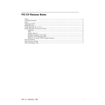
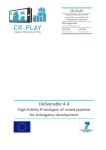
HiPic icon
After the installation of HiPic you will find the program icon in the program
group "HiPic 32". Start the program by clicking at this icon or by another common method used under Windows. After HiPic has been started the initialisation dialogue box is displayed.
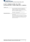
Hipic Introduction screen
20 • Starting the program
High Performance Image Control System, HiPic
Initialisation
You have to choose several basic settings which refer to your system configuration in the initialisation dialogue window.
CCD camera access
Select Internal drivers when a camera which is supported by HiPic internal
camera drivers shall be used. (Most cameras using a frame grabber use this
method). Then make the settings for frame grabber, camera type and configuration file as described below.
Select DCam API modules when a camera which is supported by a DCAM
API module shall be used (e.g. cameras with IEEE1394 interface). No additional
settings are required. The camera will be automatically detected.
When Internal drivers is selected, you have to make following settings:
Frame Grabber
Please select the frame grabber which is installed in your system.
• If no frame grabber is installed you can select the type None.
• Select IC-PCI+AM-DIG if you have the IC-PCI board installed with a
digital input module.
• Select IC-PCI+AM-VS if you have the IC-PCI board installed with an
analog input module.
• Select PCDig if you have the PCDig board installed which has a digital input module.
• Select PCVision if you have the PCVision board installed which has an
analog input module.
• Select PCI1422/1424 if you have the National Instruments frame grabber
installed which has a digital input module.
If you have installed more than one frame grabber of the same type in your
computer you have to select the number of the grabber which shall be used
during the actual session in the Board No.: field. Please select 0 if only one
grabber is installed.
Camera Type
Please select the camera type which is installed in your system.
When you use a digital input type frame grabber you can choose between No
camera, C4880, C4880-8x, StartHiPicOnlyC8000-10, C8000-20,
C7300-10, FlatPanel C4742-98 and C4742-95.
When you use the IC-PCI board with AM-VS module or the PCVision board
you can select No camera, C8000-20 or Analog 0 input for the Hamamatsu
C3077 and C5405 cameras or any other standard analog video camera.
If you have selected No frame grabber (None) you can only select No camera.
High Performance Image Control System, HiPic
Starting the program • 21
Configuration File
The frame grabber will be initialised by use of special configuration files. Normally a pointer to the correct file is automatically established during software installation.
During installation of the program the user is already asked for the camera he
wants to use and an entry in the initialisation file is already set specifying the
configuration file and camera.
Only if this entry is not correctly set you should enter the correct file name for
the configuration file in the text box Configuration file. (see also "Camera
Configuration Files *.cnf" on page 17). Press Get in order to open a dialogue
for the file selection.
If the software protection is not or not correctly installed (see also "Step 2: Install the software protection." on page 18) or does not contain a license for the
current application, a warning message appears and the program runs in demo
mode. The software protection is a hardware lock.
Note: The program will save your settings automatically. When you start it the
next time you will find that the previous settings are already set.
If all settings are finished you have to click OK in order to display the main program window and the LUT tool.
Getting Started
Overview
This chapter will describe first steps which may help you to start the system for
the first time and to acquire your first images. If you want to know details of operations please refer to the detailed explanations in the following chapters.
Starting with the C4742-95 Camera
This chapter refers to configurations which include a C4742-95 (ORCA or
ORCA ER) camera.
We assume that you have set up the C4742-95 camera as well as the frame grabber board and the HiPic program. For details, please refer to the C4742-95 manual and the chapter "Set-up and Installation" on page 13 of this manual.
Switch on the camera before you start the HiPic software.
Switch on the PC and start Windows. If HiPic is not yet installed under Windows, please do it now (refer to the Windows manual and the chapter "Software
Installation" on page 14).
22 • Getting Started
High Performance Image Control System, HiPic
Double-click the HiPic icon.
HiPic icon
Starting HiPic
Select camera and frame
grabber type
After the HiPic has been started the initialisation dialogue box will be displayed.
Now, please proceed with the initial system settings as described in the
chapter “Initialisation” on page 21.
Select C4742-95 from the Camera type section.
If you use another serial interface port than COM1, you have to insert the port
number in the text box on the right side of the C4742-95 option button.
Select IC-PCI+AM-DIG, if you work with an IC-PCI board, PCDig if you
work with a PCDig board or PCI1422/24 if you work with a National Instruments grabber.
Now click the OK button of the initialisation dialogue.
The main menu appears
After a few seconds HiPic will be initialised and the main menu (and perhaps a
few other windows) will be displayed.
The main menu includes the following items:
File, Setup, Acquisition, Corrections, Analysis, Display, Processing and Info.
Main menu
Now you can start an image acquisition by executing the following commands:
Click Acquisition. Now a command list will be displayed.
Or click
to display the
Live mode dialogue and click
it a second time to start Live
mode
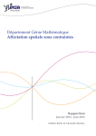
Click Live. Now the Live mode dialogue will be displayed.
High Performance Image Control System, HiPic
Getting Started • 23
C4742-95 Live mode dialogue box
The camera acquires images with default exposure time of 222 ms after you
started the Live mode by clicking the Live button.
In order to get familiar to the basic camera features, we recommend to start with
normal illumination conditions (daylight or bright field illumination) and put a
standard optical lens in front of the camera.
If you have sufficient light, you may see an image now. You can e.g. set focus
and aperture of your optical system or place the object under the camera now.
If the brightest parts of the image appear in red colour, the CCD detector is saturated. You should reduce the exposure time or the illumination level.
If you don't get a good image due to a too small amount of light, you should do
one or several of following actions:
Increase the exposure time of the C4742-95 camera with the slide bar
Exposure Time in the C4742-95 Live mode dialogue box.
LUT tool
Change the image contrast using the LUT tool.
After you started HiPic also the LUT (Look up table) tool is displayed.
Click around here
Look up table tool
This tool controls the way how an image is displayed on the display screen. By
converting grey values small changes of contrast can be enhanced.
Click
for automatic contrast enhancement.
By clicking at the right half of the top line of the LUT tool, a small red line
appears, which will indicate the uppermost grey level of the contrast enhanced image. By dragging this line with the left mouse button pressed, the
contrast will be increased or decreased.
Now you should be able to get first images with the C4742-95 camera. For details of camera settings, image processing and image storage commands, please
refer to the sections below.
Starting with the C4880 Camera
This chapter refers to configurations which include a C4880 camera.
24 • Getting Started
High Performance Image Control System, HiPic
We assume that you have set up the C4880 camera with cooling and vacuum
options as well as the frame grabber board and HiPic program. For details,
please refer to the C4880 manual and the chapter "Set-up and Installation" on
page 13 of this manual.
Please switch on the water-circulator (if you have a C4880 water-cooled type),
the monitors and the camera.
Then switch on the PC and start Windows. If HiPic is not yet installed under
Windows, please do it now (refer to the Windows manual and the chapter
“Software Installation" on page 14).
HiPic icon
There are several ways of
starting a program under
Windows. Please use the way
which is most convenient for
you.
Select camera and frame
grabber type
Click the HiPic icon.
After the HiPic has been started the initialisation dialogue box will be displayed.
Now, please proceed with the initial system settings as described in the
chapter “Initialisation” on page 21.
Select C4880 from the Camera type section.
If you use another serial interface port than COM1, you have to insert the port
number in the text box next to the C4880 radio button.
Select IC-PCI+AM-DIG, if you work with an IC-PCI board, PCDig if you
work with a PCDig board or PCI1422/24 if you work with a National Instruments grabber.
Now click the OK button of the initialisation dialogue.
After a few seconds HiPic will be initialised and the main menu (and perhaps a
few other windows) will be displayed.
The main menu shows following items:
File, Setup, Acquisition, Corrections, Analysis, Display, Processing and Info.
Main menu
Now, you can start an image acquisition by executing the following commands:
Click Acquisition. Now a command list will be displayed.
High Performance Image Control System, HiPic
Getting Started • 25
Or click
.to display the
Live mode dialogue box and
click a second time to start
Live mode immediately
Choose the Live command. Now the acquisition menu for fast scanning
mode will be displayed.
The C4880 cameras allow to work with two different scanning modes. The
fast scanning mode is mainly applicable for image adjustment (focusing),
while the high precision mode is used for precise image acquisition. In
HiPic the fast scanning mode is called "Live mode" and the high precision
mode is called "Acquire mode".)
C4880 Live mode dialogue box
After clicking the Live button, the camera starts to acquire images continuously with the default frame exposure time of 20 milliseconds. (You will
hear the mechanical shutter of the C4880 operating with the frame rate if
your C4880 is equipped with a mechanical shutter.). An image display box
will be opened. However you may not see an image yet, especially if you
work under low light level conditions. Also the cooler of C4880 does not
work yet.
Freeze Live mode
In order to stop acquisition, click Freeze. The last acquired image will be
frozen.
In order to get familiar with the basic camera features, we recommend to start
with normal illumination conditions (daylight or bright field illumination).
If you have sufficient light, you may see an image now. You can e.g. set focus
and aperture of your optical system and place your object under the camera.
How to change the exposure
time
Click Live again and change the camera exposure time by clicking the arrow on the right (left) side of the Exposure Time slide bar. The camera
exposure time is increased (decreased). Images get brighter (darker) on the
monitor now.
If the brightest parts of the image are displayed in red, the CCD detector is saturated. You should decrease the exposure time or the illumination level.
You may now want to reduce the light level more and more in order to check the
sensitivity of camera.
To get good image quality, you will have to increase the exposure time drastically (slide bar Exposure Time). However, before you do this you should
switch on the camera cooler.
Attention!: Please check if the
vacuum pump and the water
cooler (in case of water
cooling type) are switched on
and work correctly before you
turn on the camera cooler.
Otherwise the camera will not
cool down to the desired temperature and may be damaged in worst case.
26 • Getting Started
From the Setup menus select C4880 to display the camera set-up box.
Click the check button Cooler on in this menu. Now the cooler will work
and cool the detector to the default target temperature of -30°C. For
changing the target temperature, please refer to the chapter "Cooler and
Temperature Control" on page 58.
Then close the C4880 set-up menu again by clicking OK.
High Performance Image Control System, HiPic
Now you can change the exposure time to long integration times. In fast scanning mode the exposure time is limited to 10 sec. If you can't see a good image
even with a long exposure time due to the low brightness, you can try one or several of the following four methods:
Change the camera gain to "High" by clicking the High button in the Live
dialogue box. Now the camera operates with higher electrical gain.
Change the image contrast using the LUT tool.
After you started HiPic the LUT (Look up table) tool was displayed.
Click around here
Look up table tool
This tool controls the way how an image is displayed on the display screen.
Small changes of contrast can be enhanced by converting grey values.
Click
for automatic contrast enhancement
By clicking at the right half of the top line of the LUT tool, a small red line
appears, which will indicate the uppermost grey level of contrast enhanced
image. Shifting this line with the mouse (place the mouse above this line,
press the left mouse button and shift the mouse to the left or right), the
contrast will be increased or decreased.
Use the Superpixel mode of the C4880 by selecting Super-Pix. in the Live
dialogue box Scan Mode frame. Now the camera adds the charge of 4
pixels into one pixel. The image will appear smaller on the monitor, but the
camera sensitivity is increased.
Acquire mode
Change to Acquire mode and use a longer accumulation time. Under the
Acquire mode much longer accumulation times are allowed. In order to
change to Acquire mode, select the Acquire command from the Acquisition menu. Then the Acquire dialogue box appears. Now adjust the exposure time as you did in the Live mode and start an image acquisition by
clicking Acquire. One image will be acquired.
Now you should be able to acquire your first images with the C4880 camera. For
details of camera settings, image processing and image storage commands,
please refer to the sections below.
Starting with an Analog Video Camera
This chapter refers to configurations which include an analog video camera.
We assume that you have set up the camera as well as the frame grabber board,
the image display monitor and the HiPic program. For details, please refer to the
camera manual and the chapter "Set-up and Installation" on page 13 of this manual.
Switch on the camera before you start the HiPic software.
High Performance Image Control System, HiPic
Getting Started • 27
Switch on the PC and start Windows. If HiPic is not yet installed under Windows, please do it now (refer to the Windows manual and the chapter "Software
Installation" on page 14).
Double-click the HiPic icon.
HiPic icon
Starting HiPic
Select camera and frame
grabber type
After the HiPic has been started the initialisation dialogue box will be displayed.
Now, please proceed with the initial system settings as described in the
chapter “Initialisation” on page 21.
Select IC-PCI+AM-VS or PCVision according to the grabber used in your
system.
Select Analog 0 from the Camera type section.
Now click the OK button of the initialisation dialogue.
The main menu appears
After a few seconds HiPic will be initialised and the main menu (and perhaps a
few other windows) will be displayed.
Note: During initialisation the software will check if the camera delivers a
video signal to the frame grabber. If not a warning message will be issued. In
this case you should check if the camera is switched on and all cable connections are made properly.
If you are sure that it is working, you can continue to open the program.
The main menu includes the following items:
File, Setup, Acquisition, Corrections, Analysis, Display, Processing and Info.
Main menu
Now you can start an image acquisition by executing the following commands:
Click Acquisition. Now a command list will be displayed.
Or click
to display the
Live mode dialogue and click
it a second time to start Live
mode
28 • Getting Started
Click Live. Now the Live mode dialogue will be displayed.
High Performance Image Control System, HiPic
Analog video camera Live mode dialogue box
The camera acquires images after you started the Live mode by clicking the
Live button.
If the brightest parts of the image appear in red colour, the CCD detector is saturated. You should reduce the exposure time or the illumination level.
If you don't get a good image due to a too small amount of light, you can
LUT tool
Change the image contrast using the LUT tool.
After you started HiPic also the LUT (Look up table) tool is displayed.
Click around here
Look up table tool
This tool controls the way how an image is displayed on the display screen. By
converting grey values small changes of contrast can be enhanced.
Click
for automatic contrast enhancement.
By clicking at the right half of the top line of the LUT tool, a small red line
appears, which will indicate the uppermost grey level of the contrast enhanced image. By dragging this line with the left mouse button pressed, the
contrast will be increased or decreased.
Now you should be able to get first images with the camera. For details of camera settings, image processing and image storage commands, please refer to the
sections below.
High Performance Image Control System, HiPic
Getting Started • 29
Command Overview
Following list shall give you an overview about the most important commands
implemented into HiPic ., Please refer to the following chapters where you find
detailed descriptions of each command.
Command
Function (availability of several functions is depending on the camera and the frame grabber being
used.)
Acquire images
Live
Continuous acquisition and display of images, control of exposure time, gain and scan mode (Superpixel, subarray, binning etc.). C4880 cameras work
in fast scan mode.
Acquire
Single shot image acquisition with high precision,
control of exposure time, gain and scan mode (Superpixel, subarray, binning etc.). It is used for image
acquisition with high accuracy. C4880 works in
slow scan mode.
Freeze
Stops image acquisition in Live mode.
Analog Integration
Accumulation of images in the frame-buffer. This
mode is useful if the signal to noise ratio has to be
improved by averaging.
Photon Counting
Acquisition of images in photon counting mode.
This mode is useful when an image intensifier or a
streak camera is put in front of the camera. Single
photon events can be detected if this device is operated at high gain. The photon counting mode allows
to accumulate these single photon events.
Sequence
Acquisition of series of images, storage on computer memory (RAM) or hard disk. Sequence mode
can be used if a sequence of images shall be recorded with a high frequency. This command includes also a sequence replay function.
Correct Images
Background subtraction
30 • Command Overview
This function allows to subtract a background image. This can be used to subtract the camera dark
current.
High Performance Image Control System, HiPic
Shading correction
This functions allows to correct the shading of images.
Defect pixel correction This function corrects defective pixel (“dead pixel,
hot pixel”)
Average
This function allows to average images in the frame
memory.
Correction set-up
Make settings for the image correction commands.
Optimise Image Display
LUT tool
This is a tool which is used to control the contrast of
the displayed images on the screen.
Zoom
Images can be zoomed.
Analyse Images
Profile
Intensity profiles can be displayed and analysed.
This function is used to analyse intensity data of
images quantitatively. The data can be scaled in
order to allow measurement in physical units. One
intensity profile can be acquired in real-time
(QuickProfile). Data can be exported by DDE links.
QuickProfile
A special intensity profile function, which can be
used for real-time profile display
Histogram
Statistical analysis of intensity data.
Process Images
Arithmetic
Add, subtract, multiply or divide images, add offset
signals etc. This function can be used to make calculations among two images.
Superimpose
Overlay two images.
Save, Load and Print Images
Save As.., Save ROI
As.., Open..
Commands to save and load images or image sequences in IMG, TIFF or other formats.
Print
Print images
System Set-up
Camera set-up
Make settings for the camera.
Scaling set-up
Prepare scaling data for physical scaling of images
and intensity profiles.
We recommend that you read the chapters "Basic operations" on page 32 and
"Setup menu" on page 52 now.
In the chapter "Basic Operations" you will find important basic information
about the program. In the chapter "Setup menu" you will find a description about
commands for system set-up. You should be familiar to these commands before
you use the system intensively and make the set-up according to your system
configuration.
High Performance Image Control System, HiPic
Command Overview • 31
Basic operations
Overview
Several operation procedures and methods of HiPic are used throughout the
whole program. You may need the tool for contrast enhancement (LUT) whenever you work with images. You may need the tools for selecting areas of interest whenever you have to limit a zone of an image. You will find a description
about these basic operations in this chapter.
LUT Tool
The LUT tool is used to control the image display by manipulating its brightness
and contrast.
The LUT Tool
LUT Tool
If you acquire images you will find that the images are frequently displayed
with too low or too strong contrast. If you acquire images under low light level
conditions the display may be too dark. Use the LUT tool to adapt the image
display to the desired contrast. This is done by defining the lowest and highest
grey value which shall be displayed.
The tool contains an area with two cursors which represents a lower (blue cursor) and an upper limit (red cursor) for the LUT. The meaning of the values of
these cursors is described below. Cursors can be moved by clicking next to them
and dragging them while the left mouse button is pressed. When you use the
right mouse button instead both cursors will move simultaneously, keeping their
distance constant. An alternative way to move the cursors is provided by the two
sets of slide bars at the left and right side of the LUT tool. Two display boxes
(blue and red) display the exact values of the two cursors.
You can easily see how the image contrast is changed when you change the upper or lower limit.
32 • Basic operations
High Performance Image Control System, HiPic
The bottom part of the LUT shows a scale representing the input intensity values. In 8 bit mode the scale ranges from 0 to 255, in 10 bit mode from 0 to 1023,
in 12 bit mode from 0 to 4095 and in 16 bit mode from 0 to 32767.
At the centre part of the LUT tool (above the scale) a histogram is displayed
where the user can see the frequency by which intensity values are present in the
image. This histogram can be used as a guide for setting the LUT limits.
The LUT tool is re-sizeable horizontally. If the LUT tool is longer the intensity
scale can be seen and accessed with higher precision but the histogram display
will need more time to update.
LUT tool when using 32 bit image data files
When 32 bit image data file format is used (e.g. with 16 bit digital cameras) the
string “x16” in the lower left corner of the window indicates that the intensity
figures shall be multiplied by 16 to give the real intensity data values.
Upper and lower limits
HiPic allows to display images either in black and white or in pseudocolour
mode (see "LUT (Look up Table)" on page 156). The meaning of the LUT limits
is explained below for both modes.
Intensity values between the lower and the upper limit are displayed using the
full range of the LUT (either in grey-scale or in colour). The values above the
upper limit (which exceed the current LUT) are displayed in yellow (in case of
grey-scale LUT) or black (in case of colour LUT).
The uppermost intensity value of the current acquisition mode is displayed in red
(grey-scale LUT) or in white (colour LUT). Areas in these colours indicate an
overflow of the CCD camera. For 10 bit images the overflow value is 1023 and
for 12 bit images it is 4095. Be sure to reduce your light intensity if you encounter this situation. Please refer to “ Section Images” on page 79 for additional options of LUT useage.
Display mode
< blue cursor
Between cursors
> red cursor
saturation
B/W
Black
Black to white
Yellow
Red
Pseudocolor
Black
Blue to red
Black
White
B/W without
using colors
Black
Black to white
White
White
Table: Image colour-coding in different display modes
High Performance Image Control System, HiPic
Basic operations • 33
Mapping of LUT values for black and white LUT
Mapping of LUT values for colour LUT
Nonlinear contrast enhancement
The standard (default) enhancement mode offers a linear enhancement between
the lower and upper limits.
However sometimes a nonlinear enhancement function may be preferred. This
program supports two nonlinear modes: Gamma and Sigmoid.
LUT dialogue with linear contrast enhancement
34 • Basic operations
High Performance Image Control System, HiPic
In order to switch from the linear to a nonlinear mode, you have to open the
dialogue LUT in the Display menu. Click the option button of the enhancement
function which you want to use in the LUT type field. Then set the enhancement factor (Gamma-factor or sigmoid factor) by clicking and dragging the enhancement curve in the graphic box. Alternatively you can insert the desired
factor into the textbox Gamma. Then press the enter key to activate the new
factor and recalculate the image (see also „LUT (Look up Table)“ on page 156).
Automatic contrast enhancement
Automatic contrast enhancement
By clicking the small asterisk at the lower right side of the LUT tool or the corresponding button in the menu bar you can force LUT limits being calculated
automatically according to the intensity values present in the image. In most
cases this is an easy way to adapt the LUT settings to the current image and to
obtain optimum digital contrast enhancement.
Image Display
Up to 20 images can be displayed at a time. Each image has its own status. All
image processing functions refer to the currently selected image (called "current
image" in this manual). If you click to an image it becomes the current image.
Each image has its own properties concerning the LUT and colour selection. If
several images are displayed on the screen and they have different colour selection, not all images may be displayed correctly. Normally only the current image
is displayed correctly. This behaviour depends on the selected color depth of the
Windows display.
The image is always displayed within a window with specified zoom factor.
Zoom factors from 1/8 to 8 are available. When the image with the current zoom
factor does not fully fit into the window scrollbars appears on the side and only a
portion of the image is displayed (see "Zoom” on page 36).
The whole image displayed
High Performance Image Control System, HiPic
Basic operations • 35
Only a part of the image is displayed
When the window is larger than the area needed for the image a part of the window remains white.
When the image is smaller than the display window
You can freely select the size of the window. Sometimes one wants to set the
size of the window that it exactly matches the image. In such case it is sufficient
to double-click to a grey area on the image window or to select the image and
press the function key F2. When the window is smaller than the image there is a
small grey area on the lower right corner where one can click.
The caption of the window contains information about the image (image mode,
file name, zoom factor). Some functions resize the window automatically so that
the image fits into the window automatically (e.g. Acquire, Open.., Background
Subtraction).
Zoom
Zoom tool
When the Zoom tool is selected the left and right mouse buttons can be used to
change the zoom factor. When clicking with the left mouse button to the current
image area the zoom factor is increased by a factor of 2. When clicking with the
right mouse button the zoom factor is decreased by a factor of two.
The zoom factor ranges from 1/8 to 8.
The point where the user clicks to the image becomes the centre point of the image. Thus when you want to magnify a certain location it is sufficient to click to
this location with the left mouse button.
36 • Basic operations
High Performance Image Control System, HiPic
If there are scroll bars on the right or bottom side of the window, just a part of
the image is displayed. The scroll bars can be used to scroll to a location which
is currently not displayed. It is however more convenient to zoom out with the
right mouse button until the portion of the image which should be displayed becomes visible. Then click to this location with the left mouse button to magnify
it.
Selecting Regions of Interest (ROIs)
Frequently you will have to select special areas on an image. For example you
may sometimes want to save only a part of the image. In order to do this you
will need a tool to select a special area of the image, a region of interest (ROI).
On the main window of HiPic there is a group of push-buttons which allow to
set ROIs on the current image. These buttons are:
Pointing tool
Point ROI selection tool
Line ROI selection tool
Rectangular ROI selection tool
ROI move and resize tool
Display ROI info tool
The pointing tool deselects all other tools and clicking with it in an image window erases the existing ROI.
ROI
You can select an individual ROI (Region Of Interest) for every image, but each
image can have only one ROI at a time.
There are three types of ROIs: Point, Line and Rectangular ROIs. If a program
function requires such a ROI you have to select the correct ROI first and then
you can execute the function. If the wrong ROI type is currently selected the
program issues an error message and the function does not execute. To specify a
ROI proceed as follows:
Select the type of ROI by clicking to the icon on the main window tool bar.
Point ROI
Point ROI tool
Click at the desired point within the current image to select one pixel as ROI.
Line ROI
Line ROIs are straight (1-dimensional) lines with arbitrary start and end points.
They are typically used for specifying the sampling line for a profile.
Line ROI tool
Place the mouse cursor at the place within the current image where your lineROI shall start and press the left mouse button. Drag with the mouse to the desired end-point of your line ROI while you keep the left mouse button pressed.
Release the mouse button. The selected line will be displayed overlaid to the
image.
High Performance Image Control System, HiPic
Basic operations • 37
Rectangular Area ROI
Rectangular ROIs are rectangular (2-dimensional) areas. They are typically
used when saving or loading images to/from disk, when generating histograms,
and as sampling areas for vertical or horizontal profiles.
Area ROI tool
Note: If you have selected a
ROI, it will stay there (even if
the ROI border is not displayed)
until you select another ROI or
erase the ROI by clicking the
pointing tool.
Place the mouse cursor at the place within the current image where your areaROI shall start and press the left mouse button. Drag the mouse to the desired
end-point of your ROI while you keep the left mouse button pressed. Release
the mouse button. The selected (rectangular) area will be indicated by a frame.
For image processing functions which require an rectangular ROI the program
behaves as follows: When no rectangular ROI is selected the whole image area
is used for the processing, when a rectangular ROI is selected this ROI is used.
Move and Resize a ROI
Select the Move and resize tool to change an already defined ROI.
Move and resize ROIs
tool
In order to move an existing ROI, place the mouse cursor within the ROI (Area)
or next to the ROI (Line) and press the left mouse button. Than you can drag the
ROI to another location.
In order to change the size of an ROI, place the mouse cursor near the ROI and
press the right mouse button. As soon as you move the mouse while keeping the
mouse button pressed, the lower edge of the ROI will be "attached" to the cursor. You can now change the size as desired. (Not functional for point ROIs, of
course.)
Alternatively a ROI can be shifted by using the cursor keys (left, right, up,
down). Each time you press one of the keys the ROI is shifted by 1 pixel. If you
press the CTRL key + one of the cursor keys, the ROI is shifted by 10 pixel, if
you press CTRL+ALT + one of the cursor keys, the ROI is shifted by 100 pixel.
If you press the Shift key + one of the cursor keys, the lower right corner will be
shifted (ROI size is changed).
If you want to expand an ROI over the entire horizontal or vertical image area,
you can select an ROI and press H to extend the ROI over the maximum horizontal area, or V to extend it over the maximum vertical area, or F to extend it
over the full image.
Alternatively the Display ROI information tool can be used to set the size
and position of a ROI.
Display ROI info tool
If an ROI is currently displayed on the screen, you can open the ROI interface
dialogue box by clicking the Display ROI tool. Select the ROI parameter which
you want to change by clicking with the left mouse button. Then type the desired number. Repeat this for all numbers you want to change.
This way of changing the ROI size and position is especially useful when you
want to set the window very precisely (with accuracy of one pixel).
38 • Basic operations
High Performance Image Control System, HiPic
Display ROI data
Display ROI information
tool
ROI info dialogue box (example: Area ROI)
Select the Display ROI tool to display a dialogue box where several data about
the currently selected ROI are displayed. These data are:
X and Y position and intensity data in case of a point ROI.
X and Y co-ordinates of start and end point as well as length of the ROI in case
of a Line ROI.
X and Y co-ordinates of the edges of the ROI, the ROI area and the length of
ROI diagonal in case of an Area ROI.
Select the Calibrated checkbox if you want to display the data with scaling information.
The radio buttons Prf. Direction Hor. / Vert allow to choose the direction of
the QuickProfile analysis (see “QuickProfile” on page 39).
QuickProfile
With the QuickProfile function an intensity profile can be analysed and displayed in real-time. It is available during Live mode but also at any other time.
The profile is displayed as an overlay to the current image.
QuickProfile button
While the Live mode is running, but also during or after execution of another
image acquisition mode, a QuickProfile can be displayed. This is especially useful for focusing and set-up purposes. When you want to display a QuickProfile
select a rectangular ROI in the current image window. After pushing the QuickProfile button the profile will be displayed. It is overlaid with the image. Only
integrated horizontal or vertical profiles can be selected for the QuickProfile.
In order to decide the profile direction, you have two possibilities:
•
Default direction setting
Default setting can be made in the Options/ Acquisition and Display
dialogue(see “Section Acquisition” on page 78).
•
Online setting
Open the Display ROI info window by pressing the Display ROI info button. Select the checkbox Def. Direction Hor. or Ver. for the actual intensity display.
If there is a intensity distribution within the ROI which shows a clear intensity
maximum, the QuickProfile function tries to calculate the FWHM (Full width at
half maximum) value of this light peak. The result will be displayed on the left
upper corner of the image.
The QuickProfile will be automatically scaled in a way that the intensity value
given by the lower limit of LUT setting is displayed on the bottom of the image
(left of the image in case of a vertical profile) and the upper limit of LUT setting
is displayed on the top of the image (right of the image in case of a vertical profile).
High Performance Image Control System, HiPic
Basic operations • 39
Image with QuickProfile
A horizontal profile is displayed horizontally, a vertical profile is displayed vertically.
General Comments on Image Acquisition
Note: You do not need to read this chapter to understand the basic program operation but you should read it if you want to get a deeper understanding of scaling, shading correction and frame-buffer organisation. You can skip this section
now and return to it later.
Camera and Frame-buffer
To understand what happens during data acquisition it should be distinguished
between two objects:
•
The camera delivering the image.
•
The frame-buffer which stores the image and displays it.
The camera has two dimensions (X and Y) and a data depth. Here are some examples:
An analog camera such as the Hamamatsu C3077 has an 8 bit data depth and a
size of 768 x 572. The C4880-10 has a data depth of 10 or 12 bit (depending on
the acquisition mode) and a size of 1000 x 1018 (or 1008 x 1018 if scan optical
black is valid).
The frame-buffer has an overall data depth of 8, 16 or 32 bit and an area m x n
pixel. The frame buffer is always located in the PC memory.
How Areas are Transferred from Camera to
Frame-buffer
As these two objects are not identical in their general organisation structure, we
have to know how an image from the camera is transferred to the frame-buffer.
Therefore we define the following numerical parameters:
40 • Basic operations
pntOrigCh.X
The origin of the image on chip (X-direction)
pntOrigCh.Y
The origin of the image on chip (Y-direction)
pntBinning.X
Binning factor in X-direction
pntBinning.Y
Binning factor in Y-direction
areSource.X
Area on the frame buffer (X starting value)
High Performance Image Control System, HiPic
areSource.Y
Area on the frame buffer (Y starting value)
areSource.DX
Area on the frame buffer (Width in X direction)
areSource.DY
Area on the frame buffer (Width in Y direction)
Area definitions used in HiPic
The image which is read out starting at the location pntOrigCh (X,Y) on the chip
is transferred to the frame-buffer. If binning is active the image is reduced in
size according to the binning factors in both dimensions. If one knows the a.m.
numbers the chip origin of every pixel in the frame-buffer can be calculated.
This is especially necessary for scaling and shading correction:
•
When assigning a scaling to the system, every pixel on the chip is assigned
a scaled value in both dimension. For obtaining the scaled information the
pixel origin on the chip must be known.
•
Shading correction is a correction of different sensitivity of the overall system at every pixel on the chip. The correct origin on the chip must be
known for areSource in this case.
The “areSource” values describe the image area on the frame-buffer which contains a valid image. If only a part of the image is saved, these values are modified accordingly.
You can open the Image Status dialogue box (see "Image Status" on page 51)
to view the parameters of a image.
Note: If the frame grabber memory is not large enough to handle the entire image of your sensor, a smaller part of the image will be acquired starting from the
top left corner. You will see this on the status bar during acquisition.
Considering 8, 10, 12, 14, 16 and 32 bit Images
Depending on the camera and the acquisition mode the image has a certain data
type (data depth). The IC-PCI acquires images which are 8, 10, 12, 14 or 16 bit
deep. Only 16 bit images can have negative values (signed data type). During
background subtraction values are clipped to zero or negative values appear.
This is depending on the setting Clip to zero during background sub. In
the section General of tthe Setup – Options dialogue (see also “Section
General” on page 77). 8 bit images are always clipped to zero during background subtraction.
The data type of images is as follows:
Mode
Data Type
Live
8 bit (analog cameras), 10 or 12 bit (according to the version of C4880 or C474295)
High Performance Image Control System, HiPic
Basic operations • 41
Acquire
8, 10, 12,14 or 16 bit according to the
camera version
Analog integration
16 or 32 bit
Photon Counting
16 bit
The data itself are stored either in 8, 16 or 32 bit.
If the camera outputs 16 bit images the resulting images will be always 32 bit
images (to allow to store signed values). There is also an option to force the
creation of 32 bit images in Analog Integration mode (see “Section Acquisition”on page 78).
Error Handling
Though the program is carefully designed, planned, coded, tested and debugged,
software which exceeds a certain amount of code cannot be absolutely bug free
in every circumstances and with all available parameter settings. As a consequence this program also may have certain bugs which are not detected during
test but which may appear at customers site. To allow easy debugging and ensure program quality a powerful error handler has been established within this
program. When a fatal error occurs the chain of function calls and other important data is written to a file before the program is ending. This file can be used to
locate the origin of the error as quickly as possible.
When such an error occurs a message-box appears informing the user that such
an error has appeared and all information has been written to the file ERRORS.
TXT within the directory in which the programs EXE file is located. If such bug
has occurred at your side please send this file to your local Hamamatsu dealer.
In the following sections of this manual you will find detailed descriptions about
the commands of the program. You may not need to read them, as long as you
do not have specific questions about details of a command. However you should
read the chapter "Setup menu" on page 52 before you use the system extensively
and make the set-up according to your system. In the chapter "Setup menu" you
will find a description about commands for system set-up. You should be familiar with these commands .
42 • Basic operations
High Performance Image Control System, HiPic
Application Control Window
Application Control Window
After you clicked OK in the initialisation dialogue box (see Starting the program” on page 20) the application control window will appear.
Application control window
The application control window contains the menu bar, a tool bar and a status
bar on the bottom of the window.
In the status bar messages about the status of the action under progress (e.g.
"Save image file xxxx") and other important system status parameter will be displayed. If an image is loaded it also contains the size of the image in pixels.
Menu Bar
In the Application Control windows menu bar you find following topics:
File, Setup, Acquisition, Corrections, Analysis, Display, Processing,
Window (only if at least one image is displayed) and Info
The File menu offers commands for saving and loading images, for displaying
the status of the current image and for exiting the program.
The Setup menu offers commands for control of the overall behaviour of the
system.
The Acquisition menu contains commands for image acquisition.
The Corrections menu contains commands for image data corrections
High Performance Image Control System, HiPic
Application Control Window • 43
The Analysis menu contains commands for analysing image data.
The Display menu controls properties of the image display on the monitor.
The Processing menu contains commands for processing image data.
Under the Window menu the open images are listed.
The Info menu provides information about the program including its version
number and its status.
Tool Bar
The tool bar includes several push-buttons for execution of frequently used
functions. These functions are:
Icon
Name
Description / Where to find a detailed command description
Open image file
The Open Image dialogue will be displayed. See "Open" on page 50.
Save image file
The Save Image as.. window will be displayed. See "Save As .." on page 46.
Live mode
If the Live mode dialogue box is not opened, it will be opened as you click this
button for the first time. If you click it while the Live mode dialogue box is
open, image acquisition in Live mode will be started. The acquisition parameters as shown in the Live mode dialogue box are used.
Freeze Live mode
Live mode stops. The last image will be stored.
Acquire
If the Acquire mode dialogue box is not opened, it will be opened as you click
this button for the first time. If you click it while the Acquire mode dialogue box
is open, an image acquisition in Acquire mode will be executed. The acquisition parameters as shown in the Acquisition mode dialogue box are used..
Analog integration
If the Analog integration mode dialogue box is not opened, it will be opened as
you click this button for the first time. If you click it while the Analog integration mode dialogue box is open, an image acquisition in Analog integration
mode will be executed. The acquisition parameters as shown in the Analog integration mode dialogue box are used.
Photon counting
If the Photon counting mode dialogue box is not opened, it will be opened as
you click this button for the first time. If you click it while the Photon counting
mode dialogue box is open, an image acquisition in Photon Counting mode
will be executed. The acquisition parameters as shown in the Photon counting
mode dialogue box are used. See "Basics of the Photon Counting Mode" on
page 85.
Background subtrac- A background subtraction will be executed. See "Background Subtraction" on
tion
page 133.
Shading correction
Shading correction will be executed. See ""Shading Correction" on page 133.
Profile Analysis
The Profile analysis window will be opened and displayed in the foreground.
See "Profile" on page 143.
LUT
The LUT tool will be displayed. See "LUT Tool" on page 32.
Auto LUT
Automatic contrast enhancement will be made.
About
The About window will be opened. See "About" on page 167.
Pointing tool
This tool is used for deselecting the other ROI tools and for erasing an ROI
from an image. See "Basic operations" on page 32 to learn details about this and
the following tools.
44 • Application Control Window
High Performance Image Control System, HiPic
Zoom tool
If the cursor is within an image area, it will be used as zooming/dezooming tool.
Point ROI selection
tool
If the cursor is within an image area, it will be used to select an point as area of
interest.
Line ROI selection
tool
If the cursor is within an image area, it will be used as tool to select a line as
area of interest.
Rectangle ROI selection tool
If the cursor is within an image area, it will be used as tool to select a rectangular area of interest.
Modify ROI
If you set the mouse cursor within an ROI and press the left mouse button, you
can change its position, if you press the right mouse button, you can change its
size.
ROI data
A dialogue box will be opened where information about the currently selected
ROI is displayed (position, size).
QuickProfile
After selecting a rectangular ROI, the QuickProfile tool can be used to display a
intensity profile overlaid with the image data. This profile is also continuously
updated during image acquisition.
Note: Depending on the system configuration some of these push-buttons may
not be visible (e.g. if you choose the "No frame grabber mode" the push-buttons
related to acquisition are not visible: Live, Freeze, Acquire)
.
High Performance Image Control System, HiPic
Application Control Window • 45
File Menu
Overview
The File menu contains the topics Open..., Save As...,Print, Image Status
and Exit.
File menu
Save As .. and Save ROI As ..
The Save As.. command opens a dialogue box where you can input file name,
file type drive and directory name for the image file to be saved. The complete
image will be saved.
The Save ROI As.. command saves the partial image within the currently selected rectangular ROI .
Save As.. tool
Define the image area (ROI)
which shall be saved before
you invoke Save ROI As...
46 • File Menu
Choose Save As... from the File menu.
If you want to save a part of the image only, you have to select the ROI before you open the Save ROI As.. dialogue box (see also “Selecting Regions
of Interest (ROIs)" on page 37)!
High Performance Image Control System, HiPic
Save As... dialogue box
If you select Cancel the program cancels the operation.
The dialogue box behaves like a standard Windows dialogue box. It allows to
select the directory where the file shall be saved, to define new directories, to
display the file list in different formats etc.
After selecting the desired directory, you have to type the desired file name in
the File name textbox.
Note: The correct file extension (e.g. “.tif” or “.img”) will be automatically appended to the file name. If you type a file extension which is not identical to the
file extension as defined by the file type (e.g. you type “image.pix”), the correct
file extension will be appended automatically (e.g. “image.pix.tif”).
Image data are saved in a format as selected in the Save as type list. Following
formats are supported:
Save as type list
The file formats for image sequences will be available only, if the current image
is a sequence image.
•
ITEX image(*.img format).
This is one of the standard image formats (the other standard format is
“Data to TIFF image”) which maintains the full information of all images
and is compatible with all data processing functions of this program. If it is
not intended to export image data to other programs, we recommend to use
this format. See "Appendix B: Image File Format" for details of the file
format.
Notes: If a camera with 16 bit data output is used, the image files will be
saved in 16bit/pixel format. Images saved in the new 32 bit data format can
not be loaded in software versions lower than 6.1.
•
TIFF format
TIFF (Tagged Image File Format) is a widely used image format and supported by most image-processing and word-processing software packages.
High Performance Image Control System, HiPic
File Menu • 47
HiPic also supports this file format. Two types of TIFF files can be generated:
•
Display to TIFF image
If Display to TIFF image is selected, a (palletised)8 bit TIFF will be
saved.
Note: Display to TIFF will
reduce the bit depth of the
images!
The function of this command is to create a TIFF file which looks exactly like the image which you see on the display screen, including
contrast enhancement by the LUT. It does, however, not contain the
full data bit depth of the image, and hence it should not be used to store
measurement results for other than display purposes.
If you want to store HiPic
image data in another file
format than IMG or TIFF,
save them as TIFF first and
use a graphic program
(PhotoShop, Paint Shop Pro,
Corel PhotoPaint) to convert
the format.
ROI overlay and QuickProfile will not be saved.
The TIFF image looks exactly like the image which you see on the
monitor.
Note: If you want to load TIFF images within this program later on, always use the Data to TIFF image format.
Note: If the current image is part of a sequence, you have the choice, if
you want to save the full sequence or only the current image.
• Data to TIFF image
Data to TIFF image allows to save image data with full data depth in
TIFF format. The file will contain 8 or 16 bit data without the LUT
transformation.
Note: Though 16 TIFF files are true TIFF files according to their definitions, not many other programs support this relatively new data format
yet. If you are not sure whether your image analysis program can handle
these files try it and use standard TIFF, as generated with the Display
to TIFF image in the case your program cannot handle them.
Images stored in 32 bit format will be saved in 16bit/pixel format. Most
upper 16 bits are used. Lower bits are skipped.
Note: If the current image is part of a sequence, you have the choice to
save the full sequence or only the current image.
.
•
ITEX Sequence
This command allows to save a sequence of images which has been previously recorded with the Sequence function (see “Sequence” on page
124).
You have to choose the name for the first image in the sequence. The system will automatically name all other images. Sub-areas of images (ROIs)
can be selected.
48 • File Menu
High Performance Image Control System, HiPic
Note: There are two naming conventions for naming a sequence:
NAMEXXX.IMG and NAME.XXX where XXX is a numeric expression
(e.g. 001). See also chapter "Sequence image file naming conventions" on
page 128.
Choose a file name according
to the sequence image naming
convention.
Select the file format ITEX Sequence (*001.img) to save a sequence in the
format NAMEXXX.img.
Select the file format ITEX Sequence (*.001) to save a sequence in the
format NAME.XXX. Note:This format may not be supported in future versions of this program. It is only provided for compatibility reasons with
older program versions!
If you do not add any numbers to the file name, the program will automatically add numbers.
TIFF Sequence
HiPic also supports TIFF file format for image sequences. Two types of
TIFF file sequences can be generated:
•
Display to TIFF Sequence
If Display to TIFF Sequence is selected, 8 bit TIFF files will be
saved.
Note: Display to TIFF will
reduce the bit depth of the
images!
The function of this command is to create a sequence of TIFF files
which look exactly like the images which you see on the display screen,
including contrast enhancement by the LUT. They do, however, not
contain the full data bit depth of the original images, and hence this
format should not be used to store measurement results for other than
display purposes.
If you want to store HiPic
image data in another file
format than IMG or TIFF,
save them as TIFF first and
use a graphic program
(PhotoShop, Paint Shop Pro,
Corel PhotoPaint) to convert
the format.
Note: If you want to load TIFF images within this program later on,
always use the Data to TIFF image format.
The sequence will we recorded in the naming convention
NAMEXXX.tif.
• Data to TIFF Sequence
Data to TIFF Sequence allows to save image sequence data with full
data depth in TIFF format. The files will contain 8 or 16 bit data without the LUT transformation.
Note: Though 16 bit TIFF files are true TIFF files according to their
definitions, not many other programs support this relatively new data
format yet. If you are not sure whether your image analysis program can
handle these files try it and use standard TIFF, as generated with the
Display to TIFF Sequence in the case your program cannot handle
them.
Images stored in 32 bit format will be saved in 16bit/pixel format. Most
upper 16 bits are used. Lower bits are skipped.
The sequence will be recorded in the naming convention
NAMEXXX.tif.
•
ASCII image
Image data can be saved in ASCII format. The data are stored without any
High Performance Image Control System, HiPic
File Menu • 49
header information. Each pixel data is separated by a TAB character. The
end of each line is indicated by carriage return + line feed.
The data can not be read by this program. ASCII files can be read by many
spreadsheet programs like Excel and data analysis programs like Origin.
The extension *.dat is used for indicating ASCII image files.
•
ASCII Sequence
Image sequences can be saved in ASCII format using this format. The data
are stored without any header information. Each pixel data is separated by a
TAB character. The end of each line is indicated by carriage return + line
feed.
The data can not be read by this program. ASCII files can be read by many
spreadsheet programs like Excel and data analysis programs like Origin.
The naming convention NAMEXXX.dat is used for this file format.
•
DPC image file
The DPC file format is a special file format for photon counting images.
The x-y co-ordinate of each photon and the time when it was detected is
stored in these files. The file format selection *.dpc is only available when
DPC-type photon counting images are generated (for details also refer to
“Basics of the Photon Counting Mode” on page85).
File Comment
In the text box below the Save As.. or Save ROI As...dialogue you can input
a comment. This comment will be saved to disk together with the image file and
it can be used to identify the image later.
Open...
This command allows to load and display an existing image file.
The Open.. tool
The Open... command pops up a dialogue similar to the Save As... dialogue.
You have to select an image file type which you want to load and display. To
select a file you can either input a file name in the file name text box or doubleclick on the filename in the file list.
If the selected file is part of an image sequence, the sequence, starting at the
chosen file number will be loaded.
Following file types can be read by this program:
ITEX files and sequences, TIFF files and sequences (however not 24 bit colour
TIFF images), DPC files and DPC sequences (see “Dynamic Photon Counting
(time resolved 2-D photon counting)” on page 88).
File info
As soon as you have selected a file, detailed information about the actually selected file will be displayed in the File info table below the dialogue box.
50 • File Menu
High Performance Image Control System, HiPic
File info table
Print...
If you choose this command, the current image will be printed on your printer.
Image Status
The Image Status command displays a window with the image status information of the current image.
Image status control box
Exit
The Exit command terminates the program unconditionally.
Most set-up parameters will be automatically saved to disk and re-activated
when the program is started the next time.
High Performance Image Control System, HiPic
File Menu • 51
Setup menu
Overview
In the Setup menu you find all entries for setting of the system parameters. You
should read this chapter before you start to use your system extensively. You
may have to change some of the settings before you can work with your system
properly.
The Setup menu has the following entries:
Camera (Analog Camera, C4880, C4742, C4742-98, C4880-8x, C730010, C8000-10, C8000-20 depending on the camera selected in the initialisation setup), Scaling, Scaling File Editor and Options.
Setup menu
C4742-95 Set-up
Note: This menu is available if a black and white C4742-95 or C8484 type camera is used.
Some parameters may sligtly differ depending on the camera version used.
In the C4742-95 set-up dialogue box several parameters of the C4742-95 camera can be set.
Choose C4742 in the Setup menu to display the C4742-95 set-up dialogue
box.
52 • Setup menu
High Performance Image Control System, HiPic
C4742-95-12ER camera set-up dialogue box
Several basic settings of the C4742-95 can be selected here. The user normally
wants to select these settings once and keep them for some time. Therefore these
settings are stored and automatically used for your next session with HiPic .
CCD area
You can select, if the full CCD area of 1344 x 1024, a field of 1280 x 1024 or if
only a square of 1024 x 1024 pixel shall be used.
Scan Mode
The camera operation can be switched between Normal mode (full resolution),
Superpixel mode (then one of 3 Binning modes can be selected) and Subarray mode (then readout area can be user-defined). Note: Subarray mode is only
available if it is supported by the camera version.
Binning
Different binning formats can be selected. This is only available if Superpixel
or Subarray mode is selected
Timing
If Internal timing is used the exposure time is controlled from the computer
and the start of exposure from the C4742-95 camera, if External timing is
used, exposure time and/or start of exposure is generated by an external trigger
signal (please refer also to the camera manual).
If External timing is selected, two external trigger modes can be selected:
Edge or Level triggering (please refer to the camera manual for a detailed description). In Edge trigger mode the start of an exposure is defined by an external trigger. The exposure time is defined by the program.
In Level trigger mode, start of an exposure and exposure time are defined by
an external trigger signal.
If External timing is selected, there are three ways to supply the trigger signal
to the camera (Trigger source). Select BNC to supply the signal to the BNC
connector at the camera control unit. Select D-Sub, if the signal shall be sup-
High Performance Image Control System, HiPic
Setup menu • 53
plied to the D-Sub connector at the camera control unit. Select Digital I/F, if the
signal shall be supplied from the computer via the digital camera cable.
Select Trigger Polarity in accordance to the elctrical polarity of your trigger
signal.
Camera information
In this textbox the camera version and some important features of the camera are
displayed.
Light mode
This is only available for C4742-95 ER camera models.
Two different settings of the camera can be selected. In Light mode “Low” the
camera works with reduced sensitivity but maximum dynamic range, while in
Light mode “High” the camera works with maximum sensitivity at a slightly
lower dynamic range (please refer also to the camera manual).
Subarray mode
In subarray mode the dialog box changes slightly
.
C4742-95-12ER setup dialogue in subarray mode
Select the CCD area which shall be read out either by typing the desired values
in the Subarray settings sections or draw a rectangle in the area below the
Subarray settings section. Have the left mouse button pressed while you drag
from the upper left corner to the lower right corner of the desired readout area.
Press the OK button when you have finished your choice. Now the settings
come into effect.
54 • Setup menu
High Performance Image Control System, HiPic
C4742-95-12HR Set-up
Note: This menu is only available if the ORCA HR (C4742-95-12HR ) camera is
used.
In order to acquire images at full resolution with ORCA HR, Windows
2000 and PC DIG frame grabber or PCI1422/24 frame grabber with more
than 42 MB on board memeory have be used! With other configurations
not the whole image area may be captured.
In the C4742-95 set-up dialogue box several parameters of the C4742-95-12HR
camera can be set.
Choose C4742 in the Setup menu to display the C4742-95 set-up dialogue
box.
C4742-95-12HR camera set-up dialogue box
Several basic settings of the C4742-95 can be selected here. The user normally
wants to select these settings once and keep them for some time. Therefore these
settings are stored and automatically used for your next session with HiPic .
Scan mode
Four different scan modes are available:
Superpixel is a mode where square format pixel binning is supported. The binning factors as chosen in the Binning setting are applied.
Subarray is a mode where a sub-portion of the image is read out and displayed.
Binning and subarray settings are applied.
Interlace is a mode where the image is grabbed in two sub-portions. This offers
the best spatial resolution but reduces the image update rate.
Outline is a special mode where image is read out with reduced resolution but
maximum frame rate. This mode is considered for preview operations.
Binning
2 different formats can be selected. This is only available if Superpixel or
Subarray mode is selected.
Fast repeat mode (PIV)
High Performance Image Control System, HiPic
Setup menu • 55
PIV mode is a special camera acquisition mode for particle imaging velocimetry
applications. This mode is only available if the camera is equipped with the PIV
option.
If External timing and Fast repeat mode (PIV) Trigger mode is selected,
the camera will work in the special PIV mode. In this mode two images are acquired within a short time after a external trigger signal has been detected by the
camera. This mode works with Live mode and Sequence mode only.
The exposure time of the first image is defined by the exposure time setting of
the Live dialogue, the exposure time of the second image is defined by the camera frame readout time. PIV mode works only if Scan mode is Normal or Superpixel.
Timing
If Internal timing is used the exposure time is controlled from the computer
and the start of exposure from the C4742-95 camera, if External timing is
used, exposure time and/or start of exposure is generated by an external trigger
signal (please refer also to the camera manual). Only Superpixel and Subarray mode are available with External timing If External timing is selected,
two external trigger modes can be selected: Edge or Level triggering (please
refer to the camera manual for a detailed description). In Edge trigger mode
the start of an exposure is defined by an external trigger. The exposure time is
defined by the program.
In Level trigger mode, start of an exposure and exposure time are defined by
an external trigger signal.
If External timing is selected, there are three ways to supply the trigger signal
to the camera (Trigger source). Select BNC to supply the signal to the BNC
connector at the camera control unit. Select D-Sub, if the signal shall be supplied to the D-Sub connector at the camera control unit. Select Digital I/F, if the
signal shall be supplied from the computer via the digital camera cable.
Select Trigger Polarity in accordance to the electrical polarity of your trigger
signal.
Camera information
In this textbox the camera version and some important features of the camera are
displayed.
Subarray mode
In subarray mode the dialog box changes slightly
56 • Setup menu
High Performance Image Control System, HiPic
.
C4742-95-12HR setup dialogue in subarray mode
Select the CCD area which shall be read out either by typing the desired values
in the Subarray settings sections or draw a rectangle in the area below the
Subarray settings section. Have the left mouse button pressed while you drag
from the upper left corner to the lower right corner of the desired readout area.
Press the OK button when you have finished your choice. Now the settings
come into effect.
C4880 and C7190-10 Set-Up
Note: This menu is only available if a C4880 type camera is used!
In this dialogue box several operation parameters of the C4880 camera can be
set.
The chapter is split up into three parts. In the first part control of contrast enhancement and shading correction is explained, in the second part the cooling
functions are described, in the last part some additional settings are explained.
Please refer also to the C4880 manual.
Choose C4880 from the Setup menu to display the C4880 set-up display box.
High Performance Image Control System, HiPic
Setup menu • 57
C4880 set-up control box (standard)
Analog Contrast Enhancement and Shading
Control
By clicking the Panel Switch check box, you can specify whether the panel
switch on the C4880 shall be active or not. If it is selected the control on the
front panel of the C4880 is active (default). Normally you may not need to use
the panel switch.
Shading correction and analog contrast enhancement are
only effective in Live mode.
The C4880 cameras offer an analog shading control feature for the fast scan
mode. It can be used to correct uneven illumination to a certain degree. If the
Shading Control check mark is selected the four potentiometers SHADING
on the right side of the C4880 controller are active for the Live mode (fast scan
mode).
The C4880 cameras offer also an analog contrast enhancement feature for the
fast scan mode. It may be used if very strong contrast enhancement is needed by
the application (e.g. brightfield or DIC microscopy). Usually the digital contrast
enhancement function of HiPic (see “LUT Tool" on page 32) is sufficient.
With the radio-buttons within the Contrast enhancement frame you can select whether or not the contrast enhancement is active for the Live mode (fast
scan mode) and by which means the contrast enhancement is controlled.
•
When the Off radio button is selected the contrast enhancement is switched
off.
•
When the Potentiometer radio button is selected the contrast enhancement is controlled by the potentiometers located in the middle part of the C
4880 controller front panel.
•
When the Computer control radio button is selected the contrast enhancement can be controlled by the two slide bars Offset and Gain below
the Computer control radio button.
Cooler and Temperature Control
Please ensure that the vacuum pump and/or water
cooler is/are switched on before you switch on the camera cooler
The check box Cooler on selects whether the cooler of the camera is switched
on or off. After starting the HiPic program, the cooler is switched off (default)
and has to be switched on explicitly.
Attention!: Some camera versions require a vacuum pump and/or a water
cooler for correct operation. Please ensure that the vacuum pump and/or water cooler is/are switched on and work correctly before you switch on the
camera cooler. Otherwise the camera will not cool down to desired temperature and may even be damaged (if the protection circuit should fail).
The controls in the frame Temperature control the temperature of the CCD
detector of the C4880 camera.
The Actual display box displays the actual temperature of the CCD whereas the
Target edit box allows the user to specify the target temperature (from -110 to
+50 oC in steps of 5 degrees). Please check your camera manual for the recommended operation temperature.
58 • Setup menu
High Performance Image Control System, HiPic
Camera Info
Inside of the frame Camera Info several camera features, as ROM Version
(camera firmware version), Chip type and the settings of the potentiometers for
contrast enhancement (Vol. Offs. and Vol. gain) are displayed.
C4880-8x Set-Up
Note: This menu is only available if a C4880-8x type camera is used!
In this dialogue box several operation parameters of the C4880-8x camera can
be set.
Choose C4880-8x from the Setup menu to display the C4880-8x set-up display box.
C4880-8x set-up control box
Analog Contrast Enhancement
Analog contrast enhancement
is only effective in Live mode.
The C4880-8x cameras offer also an analog contrast enhancement feature for
the fast scan mode. It may be used if very strong contrast enhancement is
needed by the application (e.g. brightfield or DIC microscopy). Usually the
digital contrast enhancement function of HiPic (see “LUT Tool" on page 32) is
sufficient.
With the radio-buttons within the Contrast enhancement frame you can select whether or not the contrast enhancement is active for the Live mode (fast
scan mode) and by which means the contrast enhancement is controlled.
•
When the Off radio button is selected the contrast enhancement is switched
off.
•
When the Potentiometer radio button is selected the contrast enhancement is controlled by the potentiometers located on the right side of the C
4880 controller front panel.
•
When the Computer control radio button is selected the contrast enhancement can be controlled by the two slide bars Offset and Gain below
the Computer control radio button.
High Performance Image Control System, HiPic
Setup menu • 59
Camera Info
Inside of the frame Camera Info several camera features, as ROM Version
(camera firmware version), Chip type and the settings of the potentiometers for
contrast enhancement (Vol. Offs. and Vol. gain) are displayed.
C4742-98 Set-up
Note: This menu is only available if a C4742-98 (including the C4742-98ER and
C4742-98BT versions) type camera is used!
In the C4742-98 set-up dialogue box several parameters of the C4742-98 camera can be set.
Choose C4742-98 in the Setup menu to display the C4742-98 set-up dialogue
box. Appearance of the dialogue differs slightly depending on the camera model.
C4742-98 camera set-up dialogue box
C4742-98ER camera set-up dialogue box
60 • Setup menu
High Performance Image Control System, HiPic
Several basic settings of the C4742-98 can be selected here. The user normally
wants to select these settings once and keep them for some time. Therefore these
settings are stored and automatically used for your next session with HiPic .
Light mode
This is only available for C4742-985 ER camera models.
Two different settings of the camera can be selected. In Light mode “Low” the
camera works with reduced sensitivity but maximum dynamic range, while in
Light mode “High” the camera works with maximum sensitivity at a slightly
lower dynamic range (please refer also to the camera manual).
Timing
If Internal timing is used the exposure time is controlled from the computer
and the start of exposure from the C4742-98 camera, if External timing is
used, exposure time and/or start of exposure is generated by an external trigger
signal (please refer also to the camera manual).
If External timing is selected, two external trigger modes can be selected:
Edge or Level triggering (please refer to the camera manual for a detailed description). In Edge trigger mode the start of an exposure is defined by an external trigger. The exposure time is defined by the program.
In Level trigger mode, start of an exposure and exposure time are defined by
an external trigger signal.
Select Trigger Polarity in accordance to the electrical polarity of your trigger
signal.
Shutter control
This is available for C4742-98 BT type cameras only.
If Open is selected the shutter will be always open. If Close is selected, the
shutter will be always closed. If Close on readout is selected, the shutter will
be automatically oipened during exposure time.
Camera information
In this textbox the camera version and some important features of the camera are
displayed.
Press the OK button when you have finished your choice. Now the settings
come into effect.
C7300-10 Set-up
Note: This menu is only available if a black and white C7300-10 type camera is
used!
In the C7300-10 set-up dialogue box several parameters of the C7300-10 camera can be set.
Choose C7300-10 in the Setup menu to display the C7300-10 set-up dialogue
box.
High Performance Image Control System, HiPic
Setup menu • 61
C7300-10 camera set-up dialogue box
Several basic settings of the C7300-10 can be selected here. The user normally
wants to select these settings once and keep them for some time. Therefore these
settings are stored and automatically used for your next session with HiPic .
Note: The size 1280 x 1024
with 1x1 binning can not be
selected if a IC-PCI frame
grabber with 2 Megabyte
frame memory is installed in
your computer.
CCD area
You can select, if the full CCD area shall be read out 1280 x 1024 or if only a
square of 1024 x 1024 pixel shall be used.
Scan Mode
Normal: The full CCD area is read out with full resolution
Superpixel: The camera works with 2x2 pixel binning if this scan mode is selected.
Subarray: Only a part of the CCD area is read out. Inn horizontal direction always full lines are read out while in vertical direction a smaller readout area can
be selected. The area can be selected with the sliders for the vertical offset (start
line) and width (of scan area) below the Scan Mode selection buttons.
Timing
If Internal timing is used the exposure time is controlled from the computer and
the start of exposure from the C4742-95 camera, if External timing is used,
exposure time and/or start of exposure is generated by an external trigger signal
(please refer also to the camera manual).
Fast repeat mode (PIV)
62 • Setup menu
High Performance Image Control System, HiPic
PIV mode is a special camera acquisition mode for particle imaging velocimetry
applications.
If External timing and Fast repeat mode (PIV) Trigger mode is selected,
the camera will work in the special PIV mode. In this mode two images are acquired within a short time after a external trigger signal has been detected by the
camera. This mode works with Live mode and Sequence mode only.
The exposure time of the first image is defined by the exposure time setting of
the Live dialogue, the exposure time of the second image is defined by the camera frame readout time. PIV mode works only if Scan mode is Normal or Superpixel.
Please refer to the section about PIV mode in the C7300-10 camera manual for
details of the signal timing.
How to acquire images in PIV mode:
The Live mode can be used for checking of the camera settings and settings of
the experiment.
Set the camera to PIV mode as described above. Open the Live dialog and press
Live to start image acquisition (see “
Live Mode” on page 99). After each external trigger signal two images will be
acquired. However only the first image will be displayed.
The Sequence mode can be used to acquire sequences of PIV images.
Open the Sequence dialog (see “Sequence” on page 124) and choose Cycle
features Full speed with acquisition mode Live. Please make sure that Always display image option is not selected. Set No. of loops to 2 if just a
pair of images shall be acquired. If e.g. 5 pairs shall be recorded, set it to 10.
Press Start Acquisition to start the image acquisition. After each external
trigger signal, 2 consecutive images will be acquired and stored.
If External timing is selected, two external trigger modes can be selected:
Edge or Level triggering (please refer to the camera manual for a detailed description). In Edge trigger mode the start of an exposure is defined by an external trigger. The exposure time is defined by the program.
In Level trigger mode, start of an exposure and exposure time are defined by
an external trigger signal.
If External timing is selected, there are three ways to supply the trigger signal
to the camera (Trigger source). Select BNC to supply the signal to the BNC
connector at the camera control unit. Select D-Sub, if the signal shall be supplied to the D-Sub connector at the camera control unit. Select Digital I/F, if the
signal shall be supplied from the computer via the digital camera cable.
Select Trigger Polarity in accordance to the electrical polarity of your trigger
signal.
Camera information
In this textbox the camera version and some important features of the camera are
displayed.
High Performance Image Control System, HiPic
Setup menu • 63
Press the OK button when you have finished your choice. Now the settings
come into effect.
C8000-10 Set-up
Note: This menu is only available if the C8000-10 camera is used.
In the C8000-10 set-up dialogue box several parameters of the C8000-10 camera can be set.
Choose C8000 in the Setup menu to display the C8000-10 set-up dialogue
box.
C8000-10 camera set-up dialogue box (superpixel mode)
Several basic settings of the C8000-20 can be selected here. The user normally
wants to select these settings once and keep them for some time. Therefore these
settings are stored and automatically used for your next session with HiPic .
Binning
4 different formats can be selected.
Timing
If Internal timing is used the exposure time is controlled from the computer
and the start of exposure from the C4742-95 camera, if External timing is
used, exposure time and/or start of exposure is generated by an external trigger
signal (please refer also to the camera manual).
If External timing is selected, two external trigger modes can be selected:
Edge or Level triggering (please refer to the camera manual for a detailed description). In Edge trigger mode the start of an exposure is defined by an external trigger. The exposure time is defined by the program.
In Level trigger mode, start of an exposure and exposure time are defined by
an external trigger signal.
Select Trigger Polarity in accordance to the electrical polarity of your trigger
signal.
64 • Setup menu
High Performance Image Control System, HiPic
Camera information
In this textbox the camera version and some important features of the camera are
displayed.
Subarray mode
In subarray mode the dialog box changes slightly
.
C8000-10 setup dialogue in subarray mode
Select the CCD area which shall be read out either by typing the desired values
in the Subarray settings sections or draw a rectangle in the area below the Subarray settings section. Have the left mouse button pressed while you drag from the
upper left corner to the lower right corner of the desired readout area.
Press the OK button when you have finished your choice. Now the settings
come into effect.
C8000-20 Set-up
This command is only available if a C8000-20 camera is used.
A window with camera status information is displayed.
C8000-20 setup dialog
High Performance Image Control System, HiPic
Setup menu • 65
C7921/C7942/C7943 Set-up
Note: This menu is only available if the C7921, C7942 or C7943 Flat Panel
Sensors are used.
In order to acquire images at full resolution with these sensors, Windows
2000 and PC DIG or PCI 1422/24 frame grabber have be used! With other
configurations not the whole image area may be captured.
In the Flat Panel set-up dialogue box several parameters of the C7942/C7943
can be set.
Choose Flat Panel in the Setup menu to display the C7942/C7943 set-up dialogue box.
C7921/C7942/C7943 camera set-up dialogue box (superpixel mode)
Several basic settings of the Sensor can be selected here. The user normally
wants to select these settings once and keep them for some time. Therefore these
settings are stored and automatically used for your next session with HiPic .
Binning
3 different formats can be selected.
Timing
If Internal timing is used the exposure time is controlled by the sensor,. The
exposure time is then determined by the sensor model and binning mode. Iif
External timing is used, exposure time and/or start of exposure is controlled
by an trigger signal generated by the frame grabber. The user can set the exposure time in the acquisition dialogue (please refer also to the camera manual).
Camera information
In this textbox the camera version and some important features of the camera are
displayed.
66 • Setup menu
High Performance Image Control System, HiPic
Analog Camera Set-up (IC-PCI with AM-VS or PCVision
only)
Note: This command is only available if you use a configuration with the PCVision or the IC-PCI board with the AM-VS input module attached in combination
with an analog video camera.
This feature allows the user to set-up the analog video camera.
According to the type of camera used and according to some internal camera
settings different drive methods for the cameras are supported. Please check
your actual configuration before you make following settings. If you are not sure
which setting is applicable, please consult your camera supplier.
If you choose Analog camera from the Setup menu the Analog camera setup dialogue box will be opened.
Attention: Do not remove the
camera cable while your
computer is switched on. Do
not open the computer before
you disconnected the power
line.
You have to tell the program whether the camera runs with internal sync or
should be driven externally.
For use with IC-PCI and AM-VS only: The program then tells you about the
jumper settings on the AM-VS module. Please check whether they are correctly
set on your frame grabber. Otherwise please modify them.
Analog camera set-up for internal sync
High Performance Image Control System, HiPic
Setup menu • 67
Analog camera set-up for external sync (C3077 or C5405 only).
The option Start Acquisition for sequence mode allows to choose, if
grabbing of a sequence starts with the next field or with the next odd or even
field (See also „Sequence“ on page124).
Scaling Set-up
HiPic allows to assign a scale to the horizontal and vertical axis of an image. In
the scaling set-up the scaling information is assigned to the system, to the current image or to intensity profiles.
First you can learn what scaling means in this program. Then you get an introduction to the different scaling methods (linear and table type) used in HiPic . In
the section "System, Image and Profile Scaling" you learn about the hierarchical ordering of scaling. The following chapters show how to make the set-up of
scaling for the different methods.
68 • Setup menu
High Performance Image Control System, HiPic
Introduction to Scaling
Due to practical considerations a scaling scheme is implemented which is easy
What is Scaling?
When acquiring images with a two-dimensional camera, light intensities are measured at certain detector elements. These elements are called pixels. Of course there is some spatial relationship (correspondence) between the pixels and the real world. The camera may look into a room with an ordinary
objective lens, or it may look at some microscope image, or it may be used as a sensor behind a spectrograph or streak camera. In all cases there is a specific spatial correspondence between the image on
the camera and the real world. Scaling is a way to get quantitative information about the real world by
extracting data from the camera image.
The geometrical transformations made during scaling process may be simple or more complicated depending on the type of transformation the physical measure undergoes in the complete system:
The simplest (and most often used) way of scaling is to attach a single scaling factor to the system.
The pixel distance from one point to the next is then just multiplied by that factor.
The most general way of scaling is to allow a totally free mathematical co-ordinate transformation
function like:
X_scaled =X_scaled (X_camera,Y_camera)
Y_scaled =Y_scaled (X_camera,Y_camera).
Such a very general scaling method, though it is the most versatile one, has three disadvantages:
•
To perform such a scaling one would need two two-dimensional scaling arrays of the size of horizontal x vertical pixel number (x 4 byte at least).
•
Lines with X_scaled =const or Y_scaled =const are no longer straight, making it very difficult to
extract profiles along such lines (what the user typically wants to do).
•
It is very complicated to handle this scaling scheme considering how the scaling data could be
entered by the user.
to use but versatile enough for most cases. This scaling scheme has the following possibilities and restrictions:
Example image of scaling (non-linear in X and Y direction)
•
Lines with X_scaled =constant or Y_scaled =constant always have to be
parallel to the camera axes.
•
The scales in X and Y can be linear or non-linear. In the latter case they
have to be monotonous (increasing or decreasing).
High Performance Image Control System, HiPic
Setup menu • 69
•
Non-linear scaling is realised by function tables (called Table Scaling) and
any functional relationship can be modelled freely by the user, as long as
the "monotony condition" is met.
•
Linear scaling in both dimension enables the user to measure data along any
arbitrary direction (also non-parallel to the axes).
Linear and Table Scaling
The system scaling contains two sets of scaling data. One for the X axis and one
for the Y axis. Each scaling axis can either be of linear or of table type.
The linear scaling consists of a scaling factor and a unit. When the unit is the
same for both directions and the scaling is linear in both axes, the scaling information can be attached to profiles generated in any arbitrary direction (see
"Scaling Method: Square Scaling" on page 72 and "Scaling Method: Free Scaling" on page 73). When the dimension is not the same in both directions or when
table scaling is used at least for one axis, only horizontal or vertical profiles can
be scaled.
When linear scaling is used the zero point for the scaling data of intensity profiles is always the starting point of the profile. The scaling of a profile therefore
looks always like:
Pixel No.
Scaling value
0
1
2
n...
0
1 * Factor
2 * Factor
n * Factor
Thus, the absolute value will depend on the location of the starting point. If
normal images are analysed this is what the user typically wants. As a consequence, however, if you want to compare two profiles they should start at the
same location. If you want to compensate an offset simply change the starting
point.
The table type scaling consists of a table of n floating point values and a unit.
n corresponds to the number of pixel in the axis. The n values reside in a scaling
file with the extension .scl and are read automatically into memory when
needed. The table may contain any values provided that they are strictly monotonous, either increasing or decreasing. (In other words, the function which
the table resembles must be invertable.)
If you want to make non-linear scaling or attach absolute values to certain pixels
or if you want to create scaling information which does not start at the value
zero (e.g. for a spectrograph) you should use table scaling. Table scaling always
yields the same scaled value at the same pixel location. Therefore absolute comparison is possible even if the profile windows do not start at the same location.
System, Image and Profile Scaling
The program distinguishes between the system scaling, the image scaling,
and the scaling for every intensity profile.
System, image and all profiles individually can have different scaling information.
The scaling which is assigned to the system is always automatically applied to
the current image at the moment the image is acquired. In case a profile is extracted from an image, the current image scaling is applied to the profile. The
70 • Setup menu
High Performance Image Control System, HiPic
system passes its scaling to the image, and the image passes its scaling to the
profiles.
For this transmission mechanism the following situations may appear:
•
The system scaling attaches information to the pixels on the chip (camera).
If the image origins on chip and on frame-buffer are not the same, the system scaling must be shifted accordingly.
•
If binning is active during image acquisition, the system scaling is modified
accordingly. This means, internally a table will be compressed accordingly,
and a scaling factor will be multiplied by the binning factor. All these
mechanisms are fully automatic and do not require special care from the
user.
•
When a profile is extracted from the frame-buffer the valid image area is
regarded and automatically checked whether the profile sampling window
is contained in the valid image area. If not, the user will be prompted to
modify the profile sampling window, extend the scaling data linearly or do
not assign any scaling information to the profile.
The scaling is always automatically attached to the images and profiles and reactivated when images and profiles are reloaded from disk. In most cases the
system scaling can also be reconstructed from the information in the image or
profile.
Scaling Set-up: Using Different Scaling Methods
The expression "scaling
method" refers to the way
how the system scaling is defined.
Choose Scaling from the Setup menu to display the Scaling set-up dialogue
box.
There are several methods to tell the system which scaling it should apply for
the X and Y axis.
Scaling set-up window
On the left side of the scaling dialogue box general information about the scaling
method can be defined whereas the right side contains control elements to specify details about the scaling.
Scaling method offers several methods for scaling input:
No Scaling, Square Scaling, Free Scaling .
See "Scaling Method: No Scaling" on page 72,, "Scaling Method: Free Scaling"
on page 73 .
High Performance Image Control System, HiPic
Setup menu • 71
Below the frame Scaling method the current system scaling parameter in
horizontal and vertical direction are displayed. The scaling factors or the scaling
file name and the unit are displayed.
The field below specifies the directory in which the scaling files reside.
When you set the system scaling you can select whether the scaling is also applied to the current image and/or to the profiles which may already exist. (Note:
This is the only way how scaling information can be applied to images or profiles after they have been acquired.)
Assign the scaling data to the current image by clicking Assign scaling to
current image and assign the scaling data to all existing profiles by clicking
Assign scaling to existing profiles. Use this with care since this overrides
any previously existing scaling information in these data sets. Normally these
checkboxes should be off.
A typical case would be that you have taken an image and extracted a profile from this image and
you now want to assign special scaling information to this profile. In this case the scaling information
should be assigned to the current image and the profiles.
If you already have assigned valid values to the system, taken some images and some profiles, and if
you then change something within your system (e.g. magnification), the scaling of the already existing data should not be changed, of course.
Therefore you can select whether you want to assign the scaling information to the image and the
profiles or not. You can even display profiles with different scaling information in one display, provided that the unit is the same.
Scaling Method: No Scaling
When the program is started for the first time No Scaling is selected by default.
No scaling is linear scaling with the factor 1 and the unit "”No unit" for the X
and Y direction.
No scaling
Scaling Method: Square Scaling
Square Scaling is linear scaling with identical factors and units in both directions.
Select Square to enable the square scaling method.
72 • Setup menu
High Performance Image Control System, HiPic
Square scaling
Square size pixel are necessary to apply the square
scaling method.
Square scaling is used in imaging applications when a camera with square pixels (like the Hamamatsu C4742-95, or the C4880-10 camera is used. For setting
of scaling one must input three values:
Pixel, Value, Unit.
The scaling is calculated in a way that the specified Pixel distance corresponds
to the length Value with the unit Unit.
The Pixel distance can also be specified interactively by selecting a line ROI
and pressing the Get button on the right side of the edit box Pixel. The distance
in pixels is automatically calculated and inserted into the edit field.
Under some circumstances the three values can also be transmitted from the current image or from a profile.
When clicking Get From Image the system scaling is passed from the scaling
assigned to the current image. In this case, the scaling is transmitted from "bottom to top", in the opposite direction than the normal (automatic) transmission
mechanism. The binning property of the image is taken into account to correctly
derive the system scaling as it has been when the image was created.
When clicking Get from profile only the scaling factor from the current profile
is derived. The full information of the image scaling is not re-established.
Scaling Method: Free Scaling
Free scaling is a method of scaling where the user can select different scaling
for the x and y direction.
Select Free Scale to enable the free scaling method.
High Performance Image Control System, HiPic
Setup menu • 73
Free scaling
The user can select the scaling type and the unit independently for both directions. For each direction five values can be specified:
Type, Pixel, Value, File and Unit.
When selecting the linear scaling, the meaning of Pixel, Value and Unit is the
same as for square scaling. The only difference to square scaling is that you are
specifying the scaling for each axis separately. Hence for horizontal scaling you
specify a horizontal pixel distance and for vertical scaling a vertical distance.
For the ease of input you have to select a rectangular ROI (see "Rectangular
Area ROI" on page 38) where either its width or its height are used to calculate
the pixel distance depending on the axis direction.
When selecting table scaling Value is no longer valid, the entry File is valid instead. By pushing the small button Get on the right side of the File entry you
can chose a scaling file from a file list. (See also the section "Scaling File Editor” on page 74 on how to create and edit scaling files).
By pushing the button Get From Image the system scaling is transmitted from
the scaling assigned to the current image. The binning property of the image is
taken into account to correctly pass the system scaling as it has been when the
image was created.
Scaling File Editor
The scaling file editor is used to create, view and edit scaling files (tables).
Scaling files are files which contain floating point entries (old type scaling files
contain 1024 or 1280 entries) in either ascending or descending order. (They
must be strictly monotonous). They are used to assign scaling information to the
system.
74 • Setup menu
High Performance Image Control System, HiPic
If you want to add new scaling tables, be sure to have the necessary data (polynomial coefficients) prepared.
Choose Scaling File Editor from the Setup menu to display the Scaling File
Editor.
Scaling File Editor
It displays the values of the floating point numbers as a graphical curve. The
display can be either integral of differential. If the display is integral the values
themselves are displayed. If the display is differential the differences of neighbouring values are displayed. One can look at values by moving a cursor to a
special location. The cursor can be stepped through all values by clicking < or >.
Additionally the display shows the filename (if any), the pixel number of the
actually displayed value, the value itself in numerical form, and an indication
whether the display is integral or differential.
As soon as the scaling file editor is opened, the main menu of the program will
be replaced by the scaling file editor menu. It includes following commands.:
Menu
Command
Function
File
Load Scaling File
Loads a scaling file into the memory and displays it.
Save Scaling File
Saves the current set of data to a scaling file on disk.
Exit
Closes the editor.
Integral Display
Display curve in integral mode.
Differential Display
Display curve in differential mode.
Create Diff. Polynomial
Opens a dialogue box where a set of scaling data
starting from a differential polynomial can be calculated.
Create Integr. Polynomial
Opens a dialogue box where a set of scaling data
starting from an integral polynomial can be calculated.
Multiply with value
Multiplies the polynomial with a value.
Add value
Adds a value to the polynomial.
Print
Print scaling file data.
Options
Functions
Load Scaling File loads a scaling file into memory and displays it. This function automatically checks whether the specified file is a valid scaling file or not.
High Performance Image Control System, HiPic
Setup menu • 75
Save Scaling File saves the current set of data to a scaling file on disk. It is
only enabled when valid scaling data are defined.
Exit closes the Scaling File Editor window.
Integral Display switches to integral display mode.
Differential Display switches to differential display mode.
Create Diff. Polynomial allows to calculate a set of scaling data starting from
a polynomial specifying the differences of data values.
Diff = A0 + A1*i + A2*i² + ...
A0: Coefficient 0
A1: Coefficient 1 etc.
An: Coefficient n (if the order of the polynomial is n)
A dialogue box Create Differential Polynomial is opened, if you choose
Create Diff. Polynomial from the Functions menu.
To create a polynomial select the order of polynomial first. Then insert the coefficients. Finally press OK to confirm the data input.
Create differential polynomial
Create Integr. Polynomial allows to calculate a set of scaling data starting
from a polynomial specifying the data values.
x
Value = ∑ A0 + A1× i + A2 × i ² + ...
0
A0: Coefficient 0
A1: Coefficient 1 etc.
An: Coefficient n (if the order of the polynomial is n)
A dialogue box Create Integral Polynomial is opened, if you choose Create
Integr. Polynomial from the Functions menu.
To create a polynomial select the order of polynomial first. Then insert the coefficients. Finally press OK to confirm the data input.
76 • Setup menu
High Performance Image Control System, HiPic
Create integral polynomial
The maximum order allowed of the polynomial is five for the integral and the
differential polynomials.
Options
Overview
Several program options can be controlled with the commands listed in the Options menu.
The dialogue is split up into four tab control sections: The section General,
Acquisition, Images and the section Sequence.
Section General
In this section some settings for the preferences of several commands can be set.
Choose the tab General to display following dialogue:
High Performance Image Control System, HiPic
Setup menu • 77
Dialogue Options, General
LUT Tool
The LUT tool
When the LUT tool option is checked the LUT tool is visible (default) after
starting the program.
User Functions
When the UserFunctions option is checked, function calls to a DLL named
CUSTOMER.DLL are enabled. With this option the user can implement his own
control and data analysis functions into (see also chapter “ User Function” on
page 160.
Restore Window Positions
If this option is checked, the program stores position and size of every window
when it is closed. The settings will be restored, when the window is opened for
the next time.
Set background color
If you click Set background color a color selection window will be displayed where you can choose the background color of the program main window.
Section Acquisition
Choose the tab Acquisition from the Options menu to display the Acquisition
options dialogue.
Acquisition and display options dialogue
Auto Backsub
When the Auto Backsub option is checked, background subtraction is automatically performed after an image acquisition. Please refer to "Background
Subtraction" on page 138 and "Background Subtraction" on page 133 for details
about Background subtraction.
78 • Setup menu
High Performance Image Control System, HiPic
Auto Shading
When the Auto Shading option is checked, shading correction is automatically
performed after an image acquisition. This menu item can only be enabled if
Auto backsub is enabled. Please refer to "Shading Correction" on page 140
and "Shading Correction" on page 133 for details about Shading correction.
Clip to zero during background sub.
If this command is selected, negative intensity data are clipped to zero. Negative
intensity data may appear after background subtraction.
Write dynamic photon counting file
If Write dynamic photon counting file is selected, the recording of photon
counting images in the special DPC file format is enabled. In a DPC files the x-y
co-ordinates of each photon and the time when it has been detected are recorded.
This allows to make a time dependent analysis of photon counting images (see
“Dynamic Photon Counting (time resolved 2-D photon counting)” on page 88).
Additional timeout
The parameter Additional timeout (sec) can be used to define an additional
timeout, after which an image acquisition will be stopped, if no response comes
from the camera.
Usually this time should be 0. Only in some special case when you get timeout
errors before an image acquisition has been finished, you may increase this parameter. Normally the timeout is automatically calculated:
Timeout = System defined timeout (derived from the exposure time) + Additional timeout (sec).
Slow Display
This function reduces image display speed. It should not be selected unless it is
evident that your computer has problems with image display speed.
32bit images in Analog Integration
If this parameter is checked, the image files of all images acquired in Analog
Integration mode (see e.g. „Analog Integration Mode“ on page 92) will have 32
bit depth. If it is not checked, the files will be 32 bit files only if the camera has
16 bit data output.
Defect pixel correction
If this parameter is checked the defect pixel correction function will be applied
for all images which are acquired newly.
Select the pixel correction map file which fits to your sensor in the File field.
(for generation of a pixel correction file please refer to “Corrections” on page
133).
Section Images
Choose the tab Images from the Options menu to display the Images options
dialogue.
High Performance Image Control System, HiPic
Setup menu • 79
Image options dialogue
Acquire always to the same window
When the option Acquire always to the same window is selected the Acquire and Analog Integration functions always use the same image window
for acquisition. This is useful to avoid that the PC memory is quickly used up for
storage of images. The default behaviour concerning new images is as follows:
The Live mode always acquires to the same window. The image load function
opens always a new image. The Acquire and Analog Integration function opens
up a new window every time they are invoked.
Warn when unsaved images are closed
When a window is closed and the image is not or not fully saved the program issues a warning prior to closing the window (default). When the checkbox is not
selected the program does not issue such a warning.
Auto LUT
When the Auto LUT option is checked the LUT is adapted automatically during
image acquisition (e.g. during analog integration and photon counting), after acquisition, background subtraction and loading an image (see also "LUT Tool" on
page 32).
Auto LUT in Live Mode
When this option is checked the image contrast will be updated by the AUTO
LUT function whenever a new image is displayed in Live mode.
Lower values always zero
When this option is checked the lower limit of the LUT will always be set to 0
when automatic LUT calculation is executed (e.g. by pressing the „*“ button of
the LUT tool or by using AUTO LUT mode). If the option is unchecked the
lower value will be calculated.
Get Histogram for Auto LUT in ROI only
When this option is checked the Auto LUT function will optimize the image
contrast for grey values which are within the boundaries of the actual ROI. This
allows to optimize the contrast based on the grey levels within a limited image
area. Please refer to the section „Rectangular Area ROI“ on page 38 for how to
set a ROI. If no ROI is selected, the whole image area will be considered as actual ROI. This function will be only active if Auto LUT is enabled.
80 • Setup menu
High Performance Image Control System, HiPic
Default zooming factor
When a new window is opened up a default zooming factor is used for the display. The radio buttons within the frame Default zooming factor is used to
define the default zooming factor.
Quick profile
In the frame QuickProfile several default parameters of the QuickProfile function can be set (see also “QuickProfile.” on page 39).
You can select the Default direction of intensity analysis by choosing either
the Horizontal or Vertical button. You can change this setting also later on at
an actual profile by changing the direction in the ROI info window. (see
“Display ROI data” on page 39)
Select Use Min. as zero for FWHM in order to calculate the FWHM data
relative to the minimum intensity value of the profile. If it is not selected, the
FWHM value will be calculated relative to the intensity value 0.
Select Display FWHM on image if the FWHM value shall be displayed on
the image. If this is selected the color and size of the FWHM digits can be selected as well as the number of digits No. of digits.
Fixed header for ITEX images
The image status information is stored in a string in the image file header. Normally the length of this string varies with its content. However, in some cases it
is desired that the header has a fixed length. If this option is checked the length
of the header is always 10K.
Section Sequence
Choose the tab Sequence from the Options menu to display the Sequence
options dialogue. This dialogue will can also be opened from the Sequence dialogue (see “Sequence” on page 124).
High Performance Image Control System, HiPic
Setup menu • 81
In the frame Sequence several default parameters of the sequence acquisition
mode can be selected.
Prompt before start
Normally a sequence acquisition is not started immediately after you clicked
Start Acquisition in the sequence acquisition dialogue (see “Sequence” on
page 124). Before the acquisition actually starts, an initialisation procedure is
executed. If Prompt before start is selected, the system will display a message box after the initialisation is completed. Sequence acquisition will be
started immediately after you click OK in this message box. This is useful if you
want to control the starting time of sequence acquisition precisely.
Enable stop
If Enable stop is selected, it will be possible to stop sequence acquisition at
any time. If it is not selected, sequence acquisition can be stopped only by the
user function (see “User Function” on page 160). Of course sequence acquisition
will stop latest when the pre-selected number of images has been acquired. If
Enable stop is selected, the sequence acquisition may be slightly slower on
older computer.
Enable wrap around
If Enable wrap around is selected, the sequence function will allow to acquire a sequence in the wrap around mode (see “Sequence” on page 124). This
function is only available, when the Enable stop is selected.
Do auto corrections after sequence
If the checkbox Do auto corrections after sequence is checked, all correction functions, as background or shading correction, are performed after a
complete sequence has been acquired. A background image will be acquired
only once at the end of the sequence. If this checkbox is unchecked, the corrections will be made after acquisition of each image. It may depend on your experiment, which mode to use: The mode Do auto correction after sequence allows a much faster processing of an image sequence. We recommend
to use it as default. However there may be circumstances which do not allow to
use this mode, e.g. if the background image is changing after each acquisition.
Then it is better to perform background subtraction immediately after an image
has been acquired with an newly acquired background image (see also
“Corrections” on page 133 and “Sequence” on page 124).
Always display image during acquisition
If this option is selected each image acquired during sequence acquisition will be
displayed. This will reduce the acquisition speed. We recommend not to select
this option if sequences shall be acquired with high speed.
Warning on
If this option is selected warning messages will be displayed before sequence
acquisition is started. It is recommended to have this option checked.
82 • Setup menu
High Performance Image Control System, HiPic
Acquisition Menu
Overview
In the Acquisition menu all commands related to image acquisition are listed.
The Acquisition menu includes the commands Live, Freeze, Acquire,
Analog Integration, Photon Counting, Clear Image and Sequence.
Acquisition menu
General
Four acquisition modes (Live, Acquire, Analog Integration and Photon Counting) can be controlled from the Acquisition tab control.
There are two ways to open this control:
1.
Choose the desired acquisition mode from the Acquisition menu.
2.
Click on the desired acquisition mode button as described below:
Live mode is a mode in which images are acquired continuously. It is intended
for monitoring images with maximum speed. It differs from other acquisition
modes from display window handling. Live images are always displayed in the
same window, while in other modes each new image can be displayed in a new
display window.
In Acquire mode the C4880 and C4742-98 cameras acquire images while the
camera readout is running in slow scan mode with a dynamic range of 12, 14 or
16 bit. It is intended for high precision measurements..
There is also an Acquire mode for C4742-95, C7300-10, C8000-10 and analog
video cameras. For these cameras Acquire mode behaves similar to the “Single
High Performance Image Control System, HiPic
Acquisition Menu • 83
exposure” mode of Live mode with the exception of different display window
handling (see Live mode”).
Analog Integration is a mode where several images from the camera are accumulated in the frame memory up to 16 bit depth.
Photon Counting is a mode in which single photon events are added up in the
frame memory. If the signal integration time is sufficiently long, a very high signal-to-noise ratio can be achieved. This mode also effectively suppresses certain
crosstalk effects inherent to some image intensifier and streak tubes. A dynamic
photon counting mode allows temporal analysis of photon counting images.
Live mode
If the Live mode dialogue box is not opened, it will be opened as you click this
button for the first time. If you click it while the Live mode dialogue box is
open, image acquisition in Live mode will be started. The acquisition parameters as shown in the Live mode dialogue box are used.
Freeze Live mode
Live mode stops. The last image will be stored.
Acquire
If the Acquire mode dialogue box is not opened, it will be opened as you click
this button for the first time. If you click it while the Acquire mode dialogue box
is open, an image acquisition in Acquire mode will be executed. The acquisition parameters as shown in the Acquisition mode dialogue box are used.
Analog integration
If the Analog integration mode dialogue box is not opened, it will be opened as
you click this button for the first time. If you click it while the Analog integration mode dialogue box is open, an image acquisition in Analog integration
mode will be executed. The acquisition parameters as shown in the Analog integration mode dialogue box are used.
Photon counting
If the Photon counting mode dialogue box is not opened, it will be opened as
you click this button for the first time. If you click it while the Photon counting
mode dialogue box is open, an image acquisition in Photon Counting mode
will be executed. The acquisition parameters as shown in the Photon counting
mode dialogue box are used. See "Basics of the Photon Counting Mode" on
page 85.
If the Acquisition tab control is opened once, you can switch between the different modes either by selecting the desired mode from the main menu or by selecting the tab corresponding to the desired mode.
The acquisition buttons work different depending on the display status of the acquisition window:
If the window is closed, it will be opened by clicking one of the buttons.
If the window is already opened, the corresponding acquisition function will
start after pressing an acquisition button. The acquisition will be made with the
parameters set in the corresponding tab control.
The Acquisition dialog can be changed in its size using the two pushbuttons on
the right side of the dialogue box.
If you want to see the whole window with all options, you have to choose the
largest size.
However after you have finished initial settings, you may not need to see all setting features of the control. Then you can make it smaller and display just the
controls you need for your work (e. g. start acquisition and set exposure).
84 • Acquisition Menu
High Performance Image Control System, HiPic
Each acquisition can be started by an hot-key and stopped by pressing the ESC
key.
Hot-keys for start of an acquisition are:
Ctrl +L
Ctrl +F
Ctrl +A
Ctrl+I
Ctrl+C
Live
Freeze
Acquire
Analog integration
Photon counting
If you use CCD camera access by DCAM API modules, a few functions described in this section may not be enabled due to preliminary program code restrictions. These limitations will be removed in future program versions.
Basically following functions are supported with DCAM API access:
-All acquisition modes (Live, Acquisition, Analog Integration, Sequence etc.)Exposure time control
–Binning (however not subarray scan)
–External trigger
–Camera information
Example: C4742 Acquisition control, Live mode (left small size, right largest
size)
Basics of the Photon Counting Mode
Photon Counting is a mode in which single photon events are added up in the
frame memory. If the signal integration time is sufficiently long, a very high signal-to-noise ratio can be achieved. This mode also effectively suppresses certain
crosstalk effects inherent to some image intensifier and streak tubes. A dynamic
photon counting mode allows temporal analysis of photon counting images.
High Performance Image Control System, HiPic
Acquisition Menu • 85
This chapter is divided into six parts. First you get an introduction to the photon
counting principle, followed by a detailed description of the three counting
methods (slice, peak, gravity) supported in this program. The next two parts give
you a step- by step introduction to the set-up for photon counting. The last
chapter describes the acquisition of dynamic photon counting images and analysis of this image type.
Conditions for Photon Counting Mode
Photon Counting requires that the system sensitivity is high enough to see single
photon events. This is not the case if a CCD camera is used without any other
light amplification device. Such a light amplification device could be an image
intensifier whose gain is set above a certain threshold.
Methods to Perform Photon Counting: Slice,
Peak Detection, Gravity
Depending on the frame grabber hardware and the camera features several image processing methods, called slice, gravity and peak detection can be used to
perform photon counting.
One common feature of all these methods is that only the portions of the image
are regarded where the intensity exceeds a certain threshold. Only these portions contribute to the result. The setting of this threshold is depending on features of the camera and of the photon spots which are recorded by the camera.
Photon counting modes
Slice
The most simple method to perform photon counting is the slice. Every pixel
which exceeds the threshold results in an increase of the frame-buffer value.
Normally every photon entering the photocathode of a detector is imaged onto
an area of several pixels (kind of spot). The frame-buffer intensity is incremented by one within this area. The size of this area depends on the resolution
86 • Acquisition Menu
High Performance Image Control System, HiPic
of the imaging system, the gain setting of the MCP (or the image intensifier) and
the threshold level. This means the overall number of counts in an area of the
frame-buffer is not identical to the number of photons. It is, however, equal to
the number of detected photons times the average area a single photoelectron
produces. As the pulse height of a photoelectron has a certain distribution that
area has a certain distribution, as well. The number of detected electrons is also
dependent on the overall system sensitivity, which means it is subject to shading
effects.
Peak Detection
The peak detection mode avoids the disadvantages of the slice mode and
yields only one count per photoelectron. The peak detection mode determines
the pixel which has the maximum count rate within the photon spot area. Only
the corresponding pixel-value in the image is incremented.
In peak detection and gravity mode there will be only one count in the image
for every photon, thus Poisson statistics is well fulfilled and a statistical analysis
can be done easily.
Center of Gravity Detection
Due to special features of a camera the exact position of a photon sometimes
cannot be localised precisely with the peak detection method. Therefore it is
sometimes necessary to perform a centre of gravity detection additionally to the
peak detection. This is done by a special gravity detection mode. For example
centre of gravity detection is recommended if there is a difference between odd
and even pixels in either x or y direction due to the (interlaced) detector readout
method.
For digital cameras the peak detection mode or the slice mode can be used,
whereas for analog video cameras the user has the choice between slice, peak
detection and gravity mode. Photon counting is realised with the PC processor.
Each frame is transferred with high speed to the PC RAM (50 - 100 Mbytes/sec)
and then analysed. The count rate is only limited by the rate how often an image
can be analysed. On modern computers the photon counting algorithm normally
can be performed in real-time, which means every frame can be analysed.
Photon Counting Setup
Before you start photon counting image acquisition a suitable threshold has to
be set. A sophisticated automatic setup routine has been implemented to automatically search for the most suitable threshold.
Open the Photon Counting dialogue and press Setup to start this routine. The
program automatically acquires Live mode images and performs histogram
analysis. Then it starts photon counting acquisition in test mode to get an optimal threshold for the given system. Finally it proposes certain values necessary
for the photon counting, as described in the chapter "Photon Counting Condition" on page 88. Depending on the detector settings and type of detector, the
procedure may take up to several ten seconds.
Note: If you did not perform Photon Counting Setup before you start photon
counting acquisition, the system will prompt you to do so first. If you prefer to
enter the threshold manually, you can answer No. This prompt is re-activated after you changed some parameters (like CCD exposure time) that can affect the
proper threshold determination.
High Performance Image Control System, HiPic
Acquisition Menu • 87
Photon counting, Proposed threshold after automatic threshold detection
Photon Counting Condition
In case that the photon spot areas of two photons overlap at the same image on
the CCD they will be recognised as only one photon event. To avoid such a
counting error the probability of a "two-photon event" should be low. A good
indication of this probability is the percentage of the image which is "covered"
by photons, in other words the percentage of the image which exceeds the
threshold. The smaller this percentage is the smaller is the probability that a
"new" photon hits an already recorded one. To keep this value small the "single
photoelectron" probability should be made small by reducing the intensity of the
light signal or minimising the single photoelectron spot size.
There is a display indicating the current percentage of pixels above the threshold
in a specified ROI. This value should not exceed a few percent (5-7%).
Dynamic Photon Counting (time resolved 2-D
photon counting)
The standard photon counting mode just accumulates the photons detected during the acquisition period. If you want to record also the time when a photon has
been detected, you can use the Dynamic Photon Counting acquisition mode. If
this mode is enabled, a DPC-type file will be generated where the x-y coordinate of each photon is registered as well as the time when it has been detected. In a later analysis step this file can be used for temporal analysis of
photon counting images.
Acquisition
To activate the dynamic photon counting mode you have to select the item
Write dynamic photon counting file in the menu Setup - Options- Display
(see “Section Acquisition” on page “78).
Then start photon counting image acquisition as described above.
Before the acquisition will start, a file name selection dialogue will be shown.
There you have to define the file name of the file where the image data will be
stored. For these files a special file extension is used: *.dpc. In this file the x-y
co-ordinates of each photon and the time (CCD frame number) when it was detected are stored. The time resolution is limited by the frame rate of the camera
you use for image acquisition.
In parallel to the data recording in the DPC file, an accumulated photon counting
image is generated as described above.
88 • Acquisition Menu
High Performance Image Control System, HiPic
Analysis
There are two ways to use dynamic photon counting image files of the DPC
format:
•
If you want to see the accumulated photon counting image without using the
time information you can load the file by selecting the “dpc file” format in
the File – Open dialogue.
•
If you want to analyze the temporal information of a DPC file you have to
open the file by selecting the “dpc sequence” format in the File – Open
dialogue. Then an image sequence will be generated from the file.
After you opened the file a dialogue box is displayed where you can set
several parameters of the image sequence which will be generated:
.
Dynamic photon counting load dialogue
In the upper part of this dialogue several basic parameters of the DPC file
are displayed, like file size, exposure time of one frame, number of exposures and total acquisition time.
In the lower part you can set parameters of the sequence which will be generated:
Start frame sets the frame of the photon counting image at which the sequence will start. Frames /image defines the number of frames which
will be accumulated for one image of the sequence and No images defines
the number of images of the sequence.
Example (shown in above dialogue): If data were recorded with 15000
camera frames and you intend to split the data into 10 images, each image
will be calculated from 1500 frames.
Set the No images parameter to define the number of sequence images
you want to generate. If the number exceeds the value (No.exposures /
Frames/image), the No images parameter will be automatically corrected.
The header of the sequence images will show the time of the first image of
the time frame.
Click OK to generate the sequence after you defined the sequence parameters. The generated sequence is a normal image sequence and can be treated
in the standard fashion.
For information about handling and analysis of image sequences please refer to the chapter “Sequence” on page 124.
You can find a description of the DPC file format in Appendix F. You can use
this if you want to use your own program for analysis of DPC files.
High Performance Image Control System, HiPic
Acquisition Menu • 89
C4742-95 (ORCA) and ORCA HR
This chapter describes the different acquisition modes of the C4742-95 camera
models including the C4742-95-12ER and C4742-95HR type.
Live Mode
Choose Live from the Acquisition menu to display the Live mode dialogue
box.
C4742-95 Live mode dialogue box (large size)
Start Live mode
Freeze (Stop) Live mode
If the dialogue is open, you click Live to starts acquisition of images. Clicking
Freeze stops the acquisition. With the Exposure Time slide bar the exposure
time can be set.
Click Single Exp. to acquire a single image.
While Live mode is running all other acquisition commands are disabled.
When the Freeze push-button is pressed the last image is displayed and a intensity histogram of this image is calculated and displayed on the LUT tool. This
serves for easy adjustment of LUT values (see "LUT Tool" on page 32 for details). The actual parameters are attached to the image. If the image is saved
these parameters are kept in the header of the image file (see also "Save " on
page 46).
A QuickProfile can be displayed during Live mode and after the acquisition has
been terminated (see "QuickProfile" on page 39 for details).
Analog Gain and Offset of the camera can also be selected in this dialogue
box. See also the chapter "C4742-95 Set-up" on page 52 and the camera manual
for details on the operation modes.
Realtime background subtraction
Realtime background subtraction is a operation where a background image is
continously subtracted from the acquired live images. This function can be used
to subtract a background like mottle image, intensity offset signals etc. from images.
90 • Acquisition Menu
High Performance Image Control System, HiPic
To execute background subtraction you have to decide if you want to acquire a
new background image or if you want to use any saved image as background:
Open the dialogue Background-Corrections setup and select or deselect the
checkbox Get real-time backsub data from camera. The way how to get
the background image depends on this setting:
-
Get real-time backsub data from camera is checked:
Acquire a new background image in Live mode with your camera by clicking the button Get BG data in the Live menu while your camera is working in Live mode.
-
Get realtime backsub data from camera is unchecked:
Use a image from file as background image (use this function if you have
stored a background image on your harddisk before). After you press the
Get BG data in the Live dialogue a file selection dialogue will be opened.
Select the file which you want to use as background image for realtime
background subtraction.
To start realtime background subtraction press Do RT Backsub while the
camera is working in Live mode.
The subtracted image is now displayed. In many cases you may have to change
the contrast settings with the LUT tool now in order display the resulting images
in good contrast.
Press Do RT Backsub again to stop realtime subtraction.
Acquire Mode
Choose Acquire from the Acquisition menu to display the Acquire mode
dialogue box.
Acquire an image in Acquire mode
The commands in this box are similar as explained under the chapter "This
chapter describes the different acquisition modes of the C4742-95 camera models including the C4742-95-12ER C4742-95HR typeEndHiPicOnly.
Live Mode" on page 90, with the exception that there is no Live mode. Only
single images can be acquired by pressing the Acquire button.
High Performance Image Control System, HiPic
Acquisition Menu • 91
C4742-95 Acquire dialogue
Analog Integration Mode
Analog Integration with C4742-95 adds a specified number of frames in the
frame memory.
Choose Analog Integration from the Acquisition menu to display the Analog integration dialogue box.
C4742-95 Analog integration
Its parameters are similar to those of the Live window (see “This chapter describes the different acquisition modes of the C4742-95 camera models including the C4742-95-12ER C4742-95HR typeEndHiPicOnly.
Live Mode” on page 90). Additionally you can specify the parameter # of Exposures in the section Integration, which determines, how many images will
be accumulated.
If Clear on start is checked, the last image which has been acquired will be
cleared. If it is not checked, new images will be added to the last image.
Analog integration mode
Press Integrate to start acquisition and integration of a number of images (as
defined under # of Exposures). Each images is acquired with an exposure
time as defined under Exposure time.
Photon Counting Mode
Choose Photon Counting from the Acquisition menu to display the Photon Counting dialogue box.
92 • Acquisition Menu
High Performance Image Control System, HiPic
Photon counting dialogue box with C4742-95 camera
Besides of the standard controls for exposure time, Gain and Offset, there are the
following parameters and commands:
Setup, Threshold, Clear on Start, Method Peak, Method Slice, # of
Exposures, Above thresh. (%).
The meaning of the other parameters are as follows:
Threshold.:
Threshold for Photon counting
# of Exposures: Number of exposures (images) to integrate
Start photon counting by
clicking this button
Clear on Start
The previously recorded image will be cleared before the
next acquisition will be executed. If this checkbutton is
unchecked, the new images will be added to the previously recorded ones.
Above thresh.
(%):
An indication how many pixels in the ROI (or if no ROI
is selected in the whole image) are above the threshold in
percent. We recommend to keep this value below 5%.
Method (Slice,
Peak)
Photon counting method
An photon counting acquisition can be started by clicking on the Count button.
C4742-98 (ORCA II)
Live Mode
Choose Live from the Acquisition menu to display the Live dialogue box .
High Performance Image Control System, HiPic
Acquisition Menu • 93
Live mode dialogue box with optional parameters
In LIVE mode the C4742-98 (ORCA II) is running continuously in fast scanning
mode with a dynamic range of 12 bit. It may be used for set-up, focusing, alignment etc. where a fast update of the image is necessary.
Start Live mode.
Freeze (stop Live mode).
Click the Live push-button to start Live mode.
Live mode starts the camera, switches the frame grabber into continuous grab
mode, selects the correct LUT.
Click Freeze to stop Live mode and Single Exp. to acquire a single image in
fast scan mode.
While Live mode is running, the Live dialogue box allows to specify the camera
parameters for the Live mode:
Exposure Time:
The exposure time can be changed by clicking on the slide bar Exposure. The
range of exposure time which can be set depends on the camera model.
Analog Amplifier Gain and Offset:
Analog Gain and Offset of the camera can also be selected in this dialogue
box. See also the chapter "C4742-98 Set-up” on page 60 and the camera manual
for details on the operation modes.
Scan Mode:
The Scan mode determines which part of the CCD sensor is read out by the
system (see the C4742-98 manual for details). The selections are: normal (full
area), subarray (a part of the sensor), or superpixel. Select one of the Normal,
Super-Pixel or Subarray radio buttons within the frame Scan Mode.
Subarray
When the Subarray scan mode is selected, the Subarray dialogue box titled
Live mode Subarray selection appears.
94 • Acquisition Menu
High Performance Image Control System, HiPic
Live mode subarray selection box
The radio buttons in the frame Horizontal sub-array region control the part
of the CCD sensor from where the image is read out. With the slide bars within
the Vertical frame the vertical region of subarray scanning is defined. The left
slide bar specifies the upper limit and the right slide bar controls the lower limit
of subarray scanning. The rectangle in the centre of the bottom part of the
Subarray dialogue box represents the full surface of the CCD sensor. The red
rectangle inside this rectangle represents the relative position of the subarray
area which is read out.
Note: The binning factor set in the super-pixel mode will be applied for the
subarray mode as well.
While Live mode is running all other acquisition commands are disabled.
When the Freeze push-button is pressed the last image is displayed and a intensity histogram of this image is calculated and displayed on the LUT tool. This
serves for easy adjustment of LUT values (see "LUT Tool" on page 32 for details). The actual parameters are attached to the image. If the image is saved
these parameters are kept in the header of the image file (see also "Save as..." on
page 46).
A QuickProfile can be displayed during Live mode (see "QuickProfile" on page
39 for details).
Realtime background subtraction
Realtime background subtraction is a operation where a background image is
continuously subtracted from the acquired live images. This function can be
used to subtract a background like mottle image, intensity offset signals etc.
from images.
To execute background subtraction you have to decide if you want to acquire a
new background image or if you want to use any saved image as background:
Open the dialogue Background-Corrections setup and select or deselect the
checkbox Get real-time backsub data from camera. The way how to get
the background image depends on this setting:
-
Get real-time backsub data from camera is checked:
Acquire a new background image in Live mode with your camera by clicking the button Get BG data in the Live menu while your camera is working in Live mode.
-
Get realtime backsub data from camera is unchecked:
Use a image from file as background image (use this function if you have
High Performance Image Control System, HiPic
Acquisition Menu • 95
stored a background image on your harddisk before). After you press the
Get BG data in the Live dialogue a file selection dialogue will be opened.
Select the file which you want to use as background image for realtime
background subtraction.
To start realtime background subtraction press Do RT Backsub while the
camera is working in Live mode.
The subtracted image is now displayed. In many cases you may have to change
the contrast settings with the LUT tool now in order display the resulting images
in good contrast.
Press Do RT Backsub again to stop realtime subtraction.
Acquire Mode
Choose Acquire from the Acquisition menu to display the Acquire mode
dialogue box.
Acquire an image in Acquire mode
Clicking the Acquire push-button on the Acquire dialogue box starts one image acquisition cycle. The frame grabber is set to single frame snap mode. The
correct LUT is selected.
While the acquisition is pending it can be interrupted by clicking Stop.
Camera parameters can only be selected while no acquisition is under progress.
Acquire mode dialogue box (maximum size)
The dialogue is similar to the Live mode dialogue box with the following exception:
The Acquire mode has three gain settings instead of two: low, high, super high
gain (select the Low, High or Super high gain with the Gain slider).
96 • Acquisition Menu
High Performance Image Control System, HiPic
Analog Integration Mode
Choose Analog Integration from the Acquisition menu to display the Analog integration dialogue box.
Its parameters are similar to those of the Live window (see “Live Mode” on
page 93). However there are additionally some controls to determine the special
integration functions.
C4742-98 Analog Integration window
First of all you can specify how many images are to be added in the frame memory by entering a number in the text box # of Exposures. Additionally you
can specify whether the existing image in the frame memory (current image)
should be cleared on start of the function or not. This features enables you to
continue an integration.
The Analog Integration function produces signed 16 bit images. Care must be
taken not to exceed the 16 bit range. In this case overflow occurs. During background subtraction negative values can occur (see also the chapters "Basic operations" on page 32 and "Background Subtraction" on page 133 for further information).
Analog integration mode
Press Integrate to start acquisition and integration of a number of images (as
defined under # of Exposures). Each images is acquired with an exposure
time as defined under Exposure time.
The parameter Exposure Time contains the time for a single image acquisition (not the overall time) and the parameter # of exposures. is set to the
number of integrated exposures. In a normal case (if the acquisition has not been
interrupted) the overall exposure time is # of Exposures x Exposure Time.
Photon Counting Mode
Choose Photon Counting from the Acquisition menu to display the Photon Counting dialogue box.
High Performance Image Control System, HiPic
Acquisition Menu • 97
When doing photon counting with the C4742-98, the camera is switched to fast
scan mode. Since the mechanical shutter is closed during readout, the ratio of
exposure time to readout time should be far below 1 in order not to waste too
much time for the readout. On the other hand, the maximum intensity which can
be counted is determined by the repetition rate (see above), so the exposure time
should not be too high. Values between 200 milliseconds and 1 second may be
recommended as starting values.
Photon counting dialogue box with C4742-98
Most of the parameters are identical to those of the Live mode dialogue box (see
“Live Mode” on page 93). The differences are the following controls: # of Exposures, Clear image on start, Threshold, Above thresh.,
The meaning of the other parameters are as follows:
Threshold.:
Threshold for Photon counting
# of Exposures: Number of exposures (images) to integrate
Start photon counting by
clicking this button
98 • Acquisition Menu
Clear on Start
The previously recorded image will be cleared before the
next acquisition will be executed. If this checkbbutton is
unchecked, the new images will be added to the previously recorded ones.
Above thresh.
(%):
An indication how many pixels in the ROI (or if no ROI
is selected in the whole image) are above the threshold in
percent. We recommend to keep this value below 5%.
Method (Slice,
Peak)
Photon counting method
A photon counting acquisition can be started by clicking on the Count button.
High Performance Image Control System, HiPic
C7300
Live Mode
Choose Live from the Acquisition menu to display the Live mode dialogue
box.
C7300-10 Live mode dialogue box (large size)
Start Live mode
Freeze (Stop) Live mode
If the dialogue is open, you click Live to starts acquisition of images. Clicking
Freeze stops the acquisition. With the Exposure Time slide bar the exposure
time can be set.
Click Single Exp. to acquire a single image.
While Live mode is running all other acquisition commands are disabled.
When the Freeze push-button is pressed the last image is displayed and a intensity histogram of this image is calculated and displayed on the LUT tool. This
serves for easy adjustment of LUT values (see "LUT Tool" on page 32 for details). The actual parameters are attached to the image. If the image is saved
these parameters are kept in the header of the image file (see also "Save " on
page 46).
A QuickProfile can be displayed during Live mode and after the acquisition has
been terminated (see "QuickProfile" on page 39 for details).
Analog Gain and Offset of the camera can also be selected in this dialogue
box. See also the chapter "C7300-10 Set-up” on page 61) and the camera manual
for details on the operation modes.
Note: C7300-10 cameras allow image acquisition in binning and subarray readout modes. A special acquisition mode called “Fast repeat mode (PIV)” is also
High Performance Image Control System, HiPic
Acquisition Menu • 99
supported. The related camera settings are made in the Setup section. Please see
“C7300-10 Set-up” on page 61 for details.
Realtime background subtraction
Realtime background subtraction is a operation where a background image is
continuously subtracted from the acquired live images. This function can be
used to subtract a background like mottle image, intensity offset signals etc.
from images.
To execute background subtraction you have to decide if you want to acquire a
new background image or if you want to use any saved image as background:
Open the dialogue Background-Corrections setup and select or deselect the
checkbox Get real-time backsub data from camera. The way how to get
the background image depends on this setting:
-
Get real-time backsub data from camera is checked:
Acquire a new background image in Live mode with your camera by clicking the button Get BG data in the Live menu while your camera is working in Live mode.
-
Get realtime backsub data from camera is unchecked:
Use a image from file as background image (use this function if you have
stored a background image on your harddisk before). After you press the
Get BG data in the Live dialogue a file selection dialogue will be opened.
Select the file which you want to use as background image for realtime
background subtraction.
To start realtime background subtraction press Do RT Backsub while the
camera is working in Live mode.
The subtracted image is now displayed. In many cases you may have to change
the contrast settings with the LUT tool now in order display the resulting images
in good contrast.
Press Do RT Backsub again to stop realtime subtraction.
Acquire Mode
Choose Acquire from the Acquisition menu to display the Acquire mode
dialogue box.
Acquire an image in Acquire mode
100 • Acquisition Menu
The commands in this box are similar as explained under the chapter "Live
Mode” on page 99, with the exception that there is no Live mode. Only single
images can be acquired by pressing the Acquire button.
High Performance Image Control System, HiPic
C7300-10 Acquire dialog
Analog Integration
Analog Integration with C7300-10 adds a specified number of frames in the
frame memory.
Choose Analog Integration from the Acquisition menu to display the Analog integration dialogue box.
C7300-10 Analog integration
High Performance Image Control System, HiPic
Acquisition Menu • 101
Its parameters are similar to those of the Live window (see “Live Mode” on
page 99). Additionally you can specify the parameter # of Exposures in the
section Integration, which determines, how many images will be accumulated.
If Clear on start is checked, the last image which has been acquired will be
cleared. If it is not checked, new images will be added to the last image.
Analog integration mode
Press Integrate to start acquisition and integration of a number of images (as
defined under # of Exposures). Each images is acquired with an exposure
time as defined under Exposure time.
Photon Counting
Choose Photon Counting from the Acquisition menu to display the Photon Counting dialogue box.
Photon counting dialogue box with C7300-10 camera
Besides of the standard controls for exposure time, Gain and Offset, there are the
following parameters and commands:
Setup, Threshold, Clear on Start, Method Peak, Method Slice, # of
Exposures, Above thresh. (%).
The meaning of the other parameters are as follows:
Threshold.:
Threshold for Photon counting
# of Exposures: Number of exposures (images) to integrate
102 • Acquisition Menu
Clear on Start
The previously recorded image will be cleared before the
next acquisition will be executed. If this checkbutton is
unchecked, the new images will be added to the previously recorded ones.
Above thresh.
(%):
An indication how many pixels in the ROI (or if no ROI
is selected in the whole image) are above the threshold in
percent. We recommend to keep this value below 5%.
High Performance Image Control System, HiPic
Method (Slice,
Peak)
Start photon counting by
clicking this button
Photon counting method
A photon counting acquisition can be started by clicking on the Count button.
C4880 (except C4880-80)
Live Mode with C4880 and C7190-10 Cameras
Choose Live from the Acquisition menu to display the Live dialogue box
Live mode dialogue box with optional parameters
In LIVE mode the C4880 is running continuously in fast scanning mode with a
dynamic range of 10 or 12 bit. It may be used for set-up, focusing, alignment
etc. where a fast update of the image is necessary.
Start Live mode.
Freeze (stop Live mode).
Click the Live push-button to start Live mode.
Live mode starts the camera, switches the frame grabber into continuous grab
mode, selects the correct LUT.
Click Freeze to stop Live mode and Single Exp. to acquire a single image in
fast scan mode.
While Live mode is running, the Live dialogue box allows to specify the camera
parameters for the Live mode:
High Performance Image Control System, HiPic
Acquisition Menu • 103
Exposure Time:
The exposure time can be changed by clicking on the slide bar Exposure. The
range of exposure time which can be set depends on the camera model.
Analog Amplifier Gain:
By clicking to the radio buttons within the frame Amp. Gain the user can select
either Low or High camera amplifier gain.
Scan Mode:
The Scan mode determines which part of the CCD sensor is read out by the
system (see the C4880 manual for details). The selections are: normal (full area),
subarray (a part of the sensor), binning (additional binning), or superpixel. Select one of the Normal, Subarray, Binning or Super-Pixel radio buttons
within the frame Scan Mode.
Subarray
When the Subarray scan mode is selected, the Subarray dialogue box titled
Live mode Subarray selection appears.
Live mode subarray selection box
The radio buttons in the frame Horizontal sub-array region control the part
of the CCD sensor from where the image is read out. With the slide bars within
the Vertical frame the vertical region of subarray scanning is defined. The left
slide bar specifies the upper limit and the right slide bar controls the lower limit
of subarray scanning. The rectangle in the centre of the bottom part of the
Subarray dialogue box represents the full surface of the CCD sensor. The red
rectangle inside this rectangle represents the relative position of the subarray
area which is read out.
Binning
When the Binning scan mode is selected, the Binning dialogue box titled LIVE
Mode Binning selection appears.
104 • Acquisition Menu
High Performance Image Control System, HiPic
Live mode binning window
The Binning dialogue box is identical to the Subarray window except two additional controls: The Hor. Bin. (Horizontal Binning) combo box and the Vert.
Bin. (Vertical Binning) edit box. By these controls the user can specify a binning factor in horizontal and vertical direction additionally .
While Live mode is running all other acquisition commands are disabled.
When the Freeze push-button is pressed the last image is displayed and a intensity histogram of this image is calculated and displayed on the LUT tool. This
serves for easy adjustment of LUT values (see "LUT Tool" on page 32 for details). The actual parameters are attached to the image. If the image is saved
these parameters are kept in the header of the image file (see also "Save as..." on
page 46).
A QuickProfile can be displayed during Live mode (see "QuickProfile" on page
39 for details).
On the bottom part of the dialogue box you can find several additional settings
in order to control several special acquisition parameter.
Shutter Control:
Auto, Open, or Close (Select one of Auto, Open, or Close from the Shutter
combo-box).
If Auto is selected the mechanical shutter of the camera is automatically opened
for every exposure and closed during every image readout (this is the default
setting).
If Open is selected, the shutter will be always open, if Close is selected, the
shutter will be always closed.
Optical Black:
Valid or Invalid (Select Invalid or Valid from the Opt. Black combo-box).
Default setting is Invalid.
Mode:
Internal, External Time, External Event, or External Stop (Select Internal
Trig., Ext.Trig./Time, Ext. Trig./Event, Ext. Trig./Level or Ext.
Trig./Stop from the Mode combo-box).
If Internal Trig. is selected the start of an acquisition and the exposure time is
controlled from HiPic .
High Performance Image Control System, HiPic
Acquisition Menu • 105
If Ext.Trig./Time is selected, the start of an acquisition is controlled from
HiPic and the exposure time is controlled by an external signal (applied to the
trigger input of the camera).
If Ext. Trig./Event is selected, exposure will start when Live has been clicked
and an external trigger has been sent to the camera. If Ext. Trig./Stop is selected the exposure will start after you click Live. It ends as soon as an external
signal is sent to the camera.
Finally, exposure time and start of exposures is controlled by an external trigger
signal, if Ext. Trig./Level is selected.
Trigger Polarity:
Positive or Negative (Select Positive or Negative from the Trigger Pol.
combo-box). You can select the trigger polarity for an external trigger signal
which may be sent to the camera.
Trigger Number:
1 to 9999 (Input a number into the Trig. Numb. edit box). This parameter determines, how many trigger signals are counted before an exposure will end.
Realtime background subtraction
Realtime background subtraction is a operation where a background image is
continuously subtracted from the acquired live images. This function can be
used to subtract a background like mottle image, intensity offset signals etc.
from images.
To execute background subtraction you have to decide if you want to acquire a
new background image or if you want to use any saved image as background:
Open the dialogue Background-Corrections setup and select or deselect the
checkbox Get real-time backsub data from camera. The way how to get
the background image depends on this setting:
-
Get real-time backsub data from camera is checked:
Acquire a new background image in Live mode with your camera by clicking the button Get BG data in the Live menu while your camera is working in Live mode.
-
Get realtime backsub data from camera is unchecked:
Use a image from file as background image (use this function if you have
stored a background image on your harddisk before). After you press the
Get BG data in the Live dialogue a file selection dialogue will be opened.
Select the file which you want to use as background image for realtime
background subtraction.
To start realtime background subtraction press Do RT Backsub while the
camera is working in Live mode.
The subtracted image is now displayed. In many cases you may have to change
the contrast settings with the LUT tool now in order display the resulting images
in good contrast.
Press Do RT Backsub again to stop realtime subtraction.
106 • Acquisition Menu
High Performance Image Control System, HiPic
Acquire Mode for Standard C4880 and C7190-10
Cameras
Choose Acquire from the Acquisition menu to display the Acquire mode
dialogue box.
Acquire an image in Acquire mode
Clicking the Acquire push-button on the Acquire dialogue box starts one image acquisition cycle. The frame grabber is set to single frame snap mode. The
correct LUT is selected).
While the acquisition is pending it can be interrupted by clicking Stop.
Camera parameters can only be selected while no acquisition is under progress.
Acquire mode dialogue box (maximum size)
The dialogue is similar to the Live mode dialogue box with the following exception:
The Acquire mode has three gain settings instead of two: low, high, super high
gain (select the Low, High or Super high gain radio buttons).
Please refer to the “Live Mode with C4880 C7190-10EndHiPicOnly Cameras”
on page 103 for a detailed description of the other functions of this dialogue.
Analog Integration Mode with C4880 and
C7190-10 Camera
Choose Analog Integration from the Acquisition menu to display the Analog integration dialogue box.
Its parameters are similar to those of the Live window (see “ Live Mode with
C4880 C7190-10EndHiPicOnly Cameras” on page 103). However there are additionally some controls to determine the special integration functions.
High Performance Image Control System, HiPic
Acquisition Menu • 107
Analog Integration window, without extended parameter settings
First of all you can specify how many images are to be added in the frame memory by entering a number in the text box # of Exposures. Additionally you
can specify whether the existing image in the frame memory (current image)
should be cleared on start of the function or not. This features enables you to
continue an integration.
The Analog Integration function produces signed 16 bit images except if a
camera with 16 bit A/D converter is used. With these cameras 32 bit images are
produced. Care must be taken not to exceed the 16 bit range (resp.32 bit). In this
case overflow occurs. During background subtraction negative values can occur
(see also the chapters "Basic operations" on page 32 and "Background Subtraction" on page 133 for further information).
Analog integration mode
Press Integrate to start acquisition and integration of a number of images (as
defined under # of Exposures). Each images is acquired with an exposure
time as defined under Exposure time.
The parameter Exposure Time contains the time for a single image acquisition (not the overall time) and the parameter # of exposures. is set to the
number of integrated exposures. In a normal case (if the acquisition has not been
interrupted) the overall exposure time is # of Exposures x Exposure Time.
Photon Counting Mode with C4880 and
C7190-10 Camera
Choose Photon Counting from the Acquisition menu to display the Photon Counting dialogue box.
When doing photon counting with the C4880, the camera is switched to fast
scan mode. Since the mechanical shutter is closed during readout, the ratio of
108 • Acquisition Menu
High Performance Image Control System, HiPic
exposure time to readout time should be far below 1 in order not to waste too
much time for the readout. On the other hand, the maximum intensity which can
be counted is determined by the repetition rate (see above), so the exposure time
should not be too high. Values between 200 milliseconds and 1 second may be
recommended as starting values.
Photon counting dialogue box with C4880
Most of the parameters are identical to those of the Live mode dialogue box (see
“ Live Mode with C4880 C7190-10EndHiPicOnly Cameras” on page 103). The
differences are the following controls: # of Exposures, Clear image on
start, Threshold, Above thresh.,
The meaning of the other parameters are as follows:
Threshold.:
Threshold for Photon counting
# of Exposures: Number of exposures (images) to integrate
Start photon counting by
clicking this button
Clear on Start
The previously recorded image will be cleared before the
next acquisition will be executed. If this checkbbutton is
unchecked, the new images will be added to the previously recorded ones.
Above thresh.
(%):
An indication how many pixels in the ROI (or if no ROI
is selected in the whole image) are above the threshold in
percent. We recommend to keep this value below 5%.
Method (Slice,
Peak)
Photon counting method
A photon counting acquisition can be started by clicking on the Count button.
High Performance Image Control System, HiPic
Acquisition Menu • 109
C4880-80
Live Mode
Choose Live from the Acquisition menu to display the Live mode dialogue
box.
Live mode window with C4880-80
Start Live mode
When you click Live the camera starts acquisition of images. Clicking Freeze
stops the acquisition.
Freeze (Stop) Live mode
A single exposure will be made if you click Single Exp.
With the Exposure Time slide bar on top of the dialogue box the exposure
time can be set. The exposure time will be displayed in units of time and frames
(please refer to the camera manual for details).
Further to the exposure time one can select between Normal scan mode and
Extended scan mode. The Extended scan mode allows to select one (and
only one) subarray region with any valid binning factor (1, 2, 4, 8, 16, or 32).
The format of the entry in the Extended mode text box is as follows:
X,Y,DX,DY,Bin, where
X:
left start co-ordinate of subarray region
Y:
upper start co-ordinate of subarray region
DX:
Width of subarray region
DY:
Height of subarray region
Bin:
Binning factor
Example 1: Full area is read out with 4 x 4 binning: 0,0,659,493,4
Example 2: A subarray, starting at pixel 100,50 with a width of 100 x 100 pixel
and 2 x 2 binning is read out:
100,50,100,100,2
110 • Acquisition Menu
High Performance Image Control System, HiPic
The camera can be controlled by an external trigger signal, if the Active
checkbox is checked.
Please refer to the C4880-80 manual for details on the scan mode.
While Live mode is running all other acquisition commands are disabled.
When the Freeze push-button is pressed the last image is displayed and a intensity histogram of this image is calculated and displayed on the LUT tool. This
serves for easy adjustment of LUT values (see "LUT Tool" on page 78 for details). The actual parameters are attached to the image. If the image is saved
these parameters are kept in the header of the image file (see also "Save as.." on
page 46).
A QuickProfile can be displayed during Live mode as well as after acquisition
has been terminated (see "QuickProfile" on page 39 for details).
Realtime background subtraction
Realtime background subtraction is a operation where a background image is
continuously subtracted from the acquired live images. This function can be
used to subtract a background like mottle image, intensity offset signals etc.
from images.
To execute background subtraction you have to decide if you want to acquire a
new background image or if you want to use any saved image as background:
Open the dialogue Background-Corrections setup and select or deselect the
checkbox Get real-time backsub data from camera. The way how to get
the background image depends on this setting:
-
Get real-time backsub data from camera is checked:
Acquire a new background image in Live mode with your camera by clicking the button Get BG data in the Live menu while your camera is working in Live mode.
-
Get realtime backsub data from camera is unchecked:
Use a image from file as background image (use this function if you have
stored a background image on your harddisk before). After you press the
Get BG data in the Live dialogue a file selection dialogue will be opened.
Select the file which you want to use as background image for realtime
background subtraction.
To start realtime background subtraction press Do RT Backsub while the
camera is working in Live mode.
The subtracted image is now displayed. In many cases you may have to change
the contrast settings with the LUT tool now in order display the resulting images
in good contrast.
Press Do RT Backsub again to stop realtime subtraction.
Acquire Mode
Choose Acquire from the Acquisition menu to display the Acquire mode
dialogue box.
Acquire an image in Acquire mode
The commands in this box are similar as explained under the chapter “Live
Mode” on page 110, with the exception that the camera will acquire images in
slow scan mode and there a 3 types of amplifier gain settings.
High Performance Image Control System, HiPic
Acquisition Menu • 111
Analog Integration Mode
Analog Integration with C4880-80 adds a specified number of frames in the
frame memory.
Choose Analog Integration from the Acquisition menu to display the Analog integration dialogue box.
C4880-80 Analog integration
Its parameters are similar to those of the Live window (see “Live Mode” on
page 110). Additionally you can specify the parameter # of Exposures in the
section Integration, which determines, how many images will be accumulated.
If Clear on start is checked, the last image which has been acquired will be
cleared. If it is not checked, new images will be added to the last image.
Analog integration mode
Press Integrate to start acquisition and integration of a number of images (as
defined under # of Exposures). Each images is acquired with an exposure
time as defined under Exposure time.
Photon Counting
Choose Photon Counting from the Acquisition menu to display the Photon Counting dialogue box.
When doing photon counting with the C4880-80, the camera is switched to fast
scan mode.
112 • Acquisition Menu
High Performance Image Control System, HiPic
Photon counting dialogue box with C4880-80
Most of the parameters are identical to those of the Live mode dialogue box (see
“ Live Mode” on page 110). The differences are the following controls: # of
Exposures, Clear image on start, Threshold, Above thresh.,
The meaning of the other parameters are as follows:
Threshold.:
Threshold for Photon counting
# of Exposures: Number of exposures (images) to integrate
Start photon counting by
clicking this button
Clear on Start
The previously recorded image will be cleared before the
next acquisition will be executed. If this check-button is
unchecked, the new images will be added to the previously recorded ones.
Above thresh.
(%):
An indication how many pixels in the ROI (or if no ROI
is selected in the whole image) are above the threshold in
percent. We recommend to keep this value below 5%.
Method (Slice,
Peak)
Photon counting method
A photon counting acquisition can be started by clicking on the Count button.
C8000
Live Mode with C8000-10 Camera
Choose Live from the Acquisition menu to display the Live mode dialogue
box.
High Performance Image Control System, HiPic
Acquisition Menu • 113
Start Live mode
Freeze (Stop) Live mode
In this dialogue box you can select Live, Freeze, Single Exp.. The program
assumes that the camera acquires already images when you start this command
and HiPic immediately starts to read these images. When you click Freeze the
image acquisition stops and the last image acquired is displayed.
Live mode dialogue box for C8000-10
A QuickProfile can be displayed during Live mode and after image acquisition
has been terminated (see "QuickProfile" on page 39 for details).
Exposure time can be set with the slider Exposure.
Analog Gain and Offset of the camera can also be selected in this dialogue
box. See also the camera manual for details on the operation modes.
Acquire Mode with C8000-10 Camera
Choose Acquire from the Acquisition menu to display the Acquire mode
dialogue box.
Acquire an image in Acquire mode
Clicking the Acquire push-button on the Acquire dialogue box starts one image acquisition cycle. The frame grabber is set to single frame snap mode. The
correct LUT is selected).
While the acquisition is pending it can be interrupted by clicking Stop.
Camera parameters can only be selected while no acquisition is under progress.
114 • Acquisition Menu
High Performance Image Control System, HiPic
Live mode dialogue box for C8000-10
Exposure time can be set with the slider Exposure.
Analog Gain and Offset of the camera can also be selected in this dialogue
box. See also the camera manual for details on the operation modes.
Note: Analog integration and Photon Counting modes are also supported for this
camera. The operation procedures are equivalent to the procedures described for
analog video cameras (see “Analog Integration” on page 121 and “Photon
Counting Mode” on page 122).
Live Mode with C8000-20 Camera
Choose Live from the Acquisition menu to display the Live mode dialogue
box.
Start Live mode
Freeze (Stop) Live mode
In this dialogue box you can select Live, Freeze, Single Exp. or Close. The
program assumes that the camera acquires already images when you start this
command and HiPic immediately starts to read these images. When you click
Freeze the image acquisition stops and the last image acquired is displayed.
Live mode dialogue box for C8000-20 cameras
A QuickProfile can be displayed during Live mode and after image acquisition
has been terminated (see "QuickProfile" on page 39 for details).
High Performance Image Control System, HiPic
Acquisition Menu • 115
Analog Gain and Offset of the camera can also be selected in this dialogue
box. See also the camera manual for details on the operation modes.
Realtime background subtraction
Realtime background subtraction is a operation where a background image is
continously subtracted from the acquired live images. This function can be used
to subtract a background like mottle image, intensity offset signals etc. from images.
To execute background subtraction you have to acquire a new background image Press Store BG in order to store the actual image as background image.
To activate realtime background subtraction check the BG Sub checkbox.
The subtracted image is now displayed. In many cases you may have to change
the contrast settings with the LUT tool now in order display the resulting images
in good contrast.
Unchek the BG Sub checkbox again to stop realtime subtraction.
Set the BG offset value in order to set an additional offset value to the background signal.
Recursive Filtering
The camera has a recursive filter function built in. Recursive filter or rolling average help to noise at the cost of time resolution.
Check the checkbox Recursive filter to activate recursive filtering and select
the filtering factor in the Number slider. The higher the number the better the
noise will be reduced.
Acquire Mode with C8000-20 Camera
Choose Acquire from the Acquisition menu to display the Acquire mode
dialogue box.
Acquire an image in Acquire mode
Clicking the Acquire push-button on the Acquire dialogue box starts one image acquisition cycle. The frame grabber is set to single frame snap mode. The
correct LUT is selected).
While the acquisition is pending it can be interrupted by clicking Stop.
Camera parameters can only be selected while no acquisition is under progress.
Acquire mode dialogue box for C8000-20 cameras
116 • Acquisition Menu
High Performance Image Control System, HiPic
Exposure time can be set with the slider Exposure.
Analog Gain and Offset of the camera can also be selected in this dialogue
box. See also the camera manual for details on the operation modes.
Realtime background subtraction
Realtime background subtraction is a operation where a background image is
continously subtracted from the acquired live images. This function can be used
to subtract a background like mottle image, intensity offset signals etc. from images.
To execute background subtraction you have to acquire a new background image Press Store BG in order to store the actual image as background image.
To activate realtime background subtraction check the BG Sub checkbox.
The subtracted image is now displayed. In many cases you may have to change
the contrast settings with the LUT tool now in order display the resulting images
in good contrast.
Uncheck the BG Sub checkbox again to stop realtime subtraction.
Set the BG offset value in order to set an additional offset value to the background signal.
Recursive Filtering
The camera has a recursive filter function built in. Recursive filter or rolling average help to noise at the cost of time resolution.
Check the checkbox Recursive filter to activate recursive filtering and select
the filtering factor in the Number slider. The higher the number the better the
noise will be reduced.
Note: Analog integration and Photon Counting modes are also supported for this
camera. The operation procedures are equivalent to the procedures described for
analog video cameras (see “Analog Integration” on page 121 and “Photon
Counting Mode” on page 122).
C7921, C7942 and C7943
Live Mode
Choose Live from the Acquisition menu to display the Live mode dialogue
box.
Start Live mode
Freeze (Stop) Live mode
In this dialogue box you can select Live, Freeze and Single Exp.. The program assumes that the camera acquires already images when you start this
command and HiPic immediately starts to read these images. When you click
Freeze the image acquisition stops and the last image acquired is displayed.
High Performance Image Control System, HiPic
Acquisition Menu • 117
Live mode dialogue box
A QuickProfile can be displayed during Live mode and after image acquisition
has been terminated (see "QuickProfile" on page 39 for details).
Exposure time
Exposure time can be set if trigger mode is set to External Trigger in the C7921
setup dialogue (see „C7921/C7942/C7943 Set-up“on page 66)
Realtime background subtraction
Realtime background subtraction is a operation where a background image is
continously subtracted from the acquired live images. This function can be used
to subtract a background like mottle image, intensity offset signals etc. from images.
To execute background subtraction you have to decide if you want to acquire a
new background image or if you want to use any saved image as background:
Open the dialogue Background-Corrections setup and select or deselect the
checkbox Get real-time backsub data from camera. The way how to get
the background image depends on this setting:
-
Get real-time backsub data from camera is checked:
Acquire a new background image in Live mode with your camera by clicking the button Get BG data in the Live menu while your camera is working in Live mode.
-
Get realtime backsub data from camera is unchecked:
Use a image from file as background image (use this function if you have
stored a background image on your harddisk before). After you press the
Get BG data in the Live dialogue a file selection dialogue will be opened.
Select the file which you want to use as background image for realtime
background subtraction.
To start realtime background subtraction press Do RT Backsub while the
camera is working in Live mode.
The subtracted image is now displayed. In many cases you may have to change
the contrast settings with the LUT tool now in order display the resulting images
in good contrast.
Press Do RT Backsub again to stop realtime subtraction.
Acquire mode
Choose Acquire from the Acquisition menu to display the Acquire mode
dialogue box.
118 • Acquisition Menu
High Performance Image Control System, HiPic
Acquire an image in Acquire mode
The commands in this box are similar as explained under the chapter "Live
Mode” on page 119 with the exception that there is no Live mode. Only single
images can be acquired by pressing the Acquire button.
Acquire mode dialogue
Analog Integration
Analog Integration with analog video cameras adds up video frames in the
frame memory during a specified time or number of frames.
Choose Analog Integration from the Acquisition menu to display the Analog integration dialogue box.
Its parameters are similar to those of the Live window. Additionally you can
specify the parameter # of Exposures in the section Integration, which determines, how many images will be accumulated..
If Clear on start is checked, the last image which has been acquired will be
cleared. If it is not checked, new images will be added to the last image.
Press Integrate to start acquisition and integration of a number of images (as
defined under # of Exposures)..
Analog Video Cameras
Live Mode
Choose Live from the Acquisition menu to display the Live mode dialogue
box.
Start Live mode
Freeze (Stop) Live mode
In this dialogue box you can select Live, Freeze, Single Exp. or Close. The
program assumes that the camera acquires already images when you start this
command and HiPic immediately starts to read these images. When you click
Freeze the image acquisition stops and the last image acquired is displayed.
High Performance Image Control System, HiPic
Acquisition Menu • 119
Live mode dialogue box for analog cameras
A QuickProfile can be displayed during Live mode and after image acquisition
has been terminated (see "QuickProfile" on page 39 for details).
Realtime background subtraction
Realtime background subtraction is a operation where a background image is
continously subtracted from the acquired live images. This function can be used
to subtract a background like mottle image, intensity offset signals etc. from images.
To execute background subtraction you have to decide if you want to acquire a
new background image or if you want to use any saved image as background:
Open the dialogue Background-Corrections setup and select or deselect the
checkbox Get real-time backsub data from camera. The way how to get
the background image depends on this setting:
-
Get real-time backsub data from camera is checked:
Acquire a new background image in Live mode with your camera by clicking the button Get BG data in the Live menu while your camera is working in Live mode.
-
Get realtime backsub data from camera is unchecked:
Use a image from file as background image (use this function if you have
stored a background image on your harddisk before). After you press the
Get BG data in the Live dialogue a file selection dialogue will be opened.
Select the file which you want to use as background image for realtime
background subtraction.
To start realtime background subtraction press Do RT Backsub while the
camera is working in Live mode.
The subtracted image is now displayed. In many cases you may have to change
the contrast settings with the LUT tool now in order display the resulting images
in good contrast.
Press Do RT Backsub again to stop realtime subtraction.
One can synchronise the acquisition to external events by using the Frame
grabber trigger. Enable this function by selecting the Active. checkbox. After
you clicked Live the system waits for the next external trigger signal. Then acquisition starts. It is possible to average several frames if you select the parameter Integrate after trig. to 2, 4 or 8 frames. This is especially useful, if you
120 • Acquisition Menu
High Performance Image Control System, HiPic
press Single exp. and want to be sure to get the whole signal from an image intensifier including the phosphor screen afterglow signal.
Acquire mode
Choose Acquire from the Acquisition menu to display the Acquire mode
dialogue box.
Acquire an image in Acquire mode
The commands in this box are similar as explained under the chapter "Live
Mode” on page 119 with the exception that there is no Live mode. Only single
images can be acquired by pressing the Acquire button.
Acquire mode dialogue for analog video cameras
Analog Integration
Analog Integration with analog video cameras adds up video frames in the
frame memory during a specified time or number of frames.
Choose Analog Integration from the Acquisition menu to display the Analog integration dialogue box.
Analog Integration window for analog cameras
High Performance Image Control System, HiPic
Acquisition Menu • 121
Its parameters are similar to those of the Live window. Additionally you can
specify the parameter # of Exposures in the section Integration, which determines, how many images will be accumulated. Each exposure takes 33 ms in
case you use an EIA type camera and 40 ms if you use a CCIR type camera.
If Clear on start is checked, the last image which has been acquired will be
cleared. If it is not checked, new images will be added to the last image.
Press Integrate to start acquisition and integration of a number of images (as
defined under # of Exposures)..
Photon Counting Mode
Choose Photon Counting from the Acquisition menu to display the Photon Counting dialogue box.
When doing photon counting with an analog camera, the frame rate is fixed (it is
defined by the video standard, e.g. for CCIR it is 25 Hz).
Photon counting dialogue box for analog cameras
There are the following parameters and commands:
Setup, Thres., Photon counting method, # of Exposures, Clear on
Start, Frame grabber trigger, Integrate after Trigger, Above threshold.
If the Setup command is selected you will be guided through a procedure to
find the optimum threshold parameter for photon counting. The program automatically acquires Live mode images (see “ Live Mode” on page 119) and performs histogram analysis. Finally it proposes certain values necessary for the
photon counting, as described in the chapter "Photon Counting Condition" on
page 88. Depending on the detector settings and type of detector, the procedure
may take up to several seconds.
The meaning of the other parameters are as follows:
Threshold:
Threshold for Photon counting
# of Exposures: Number of exposures (images) to integrate
Clear on Start
122 • Acquisition Menu
The previously recorded image will be cleared before the
next acquisition will be executed. If this check-button is
unchecked, the new images will be added to the previ-
High Performance Image Control System, HiPic
ously recorded ones.
Start photon counting by
clicking this button
Frame grabber
trigger:
The frame grabber synchronises the acquisition to external trigger events
Integrate after
Trigger
Here you can define, how many frames shall be averaged
after each Frame trigger event. This function is only
available if the IC-PCI frame grabber with AM-VS board
is used.
Above thresh.
(%):
An indication how many pixels in the ROI (or if no ROI
is selected in the whole image) are above the threshold in
percent.
Photon Counting Method
(slice, peak,
gravity)
Here you can select the photon counting method
An photon counting acquisition can be started by clicking on the Count button.
Freeze
If the camera is running in Live mode it can be stopped by selecting the Freeze
command of the Acquire menu (or press Ctrl+F keys). The last image which has
been acquired will be kept in the image memory.
Changing the Acquisition Mode
A full set of parameters is stored for all acquisition modes (e.g. Live and Acquire) mode and is restored every time the acquisition mode is changed.
The correct LUT is selected and the previously selected settings for this mode of
the LUT are restored.
In case of the C4880 the scan area is saved and restored when switching from
one acquisition mode to another. If subarray or binning mode has been selected
last time, the appropriate dialogue box is shown with the correct label. All dialogue boxes for all acquisition modes can be kept open simultaneously at the
screen, and it is convenient to switch from one to the other mode just by clicking
to the corresponding push-buttons.
When an acquisition has ended (either by clicking to the Freeze push-button in
Live mode or at the end of the readout in the other modes) a histogram is calculated and displayed on the LUT tool, and the corresponding acquisition parameters are copied into the image status and displayed in the Image Status dialogue
box if the Image status command has been selected.
Clear Image
The Clear Image command clears the image data.
High Performance Image Control System, HiPic
Acquisition Menu • 123
Sequence
In sequence acquisition mode a series of images can be acquired. Dependent on
the settings the sequence is recorded to the computer RAM (fast method, but
length of recording is limited by RAM size) or to hard disk (not so fast). The sequence function can save and load sequences and replay the sequence. Also sequences of intensity profiles can be recorded.
Note: At any time only one sequence can be active (either image or profile sequence).
Setting the acquisition parameters
Before you can start image or profile sequence acquisition, you have to make a
few initial settings.
Open the sequence dialogue by clicking Sequence in the Acquisition menu.
Then select the Data storage tab.
Sequence Data storage dialogue
Then you can choose if you want to record images on computer RAM or on a
disk.
Select Acquire Images to store image sequences.
If you select Store to RAM the sequence will be recorded to the computer
RAM. Use this in order to acquire a sequence with the highest speed. However
you may also have to consider that the RAM is limited so the number of images
you can record is limited.
If you select Store to HD, the images will be stored under the file name as defined under the file text box on your hard disk. Storing images to the hard disk is
not as fast as storing images on the RAM, however your hard disk may have a
larger capacity.
If you select Acquire and store defined profiles, all intensity profiles with
defined and displayed ROIs will be stored. You have to select the file name in
the file text box. Profile sequences are always stored to disk.
124 • Acquisition Menu
High Performance Image Control System, HiPic
Image Sequences
Image Sequence acquisition
To acquire a sequence proceed as follows:
First of all start the acquisition for which you want to record a sequence (Live,
Analog Integration, Photon Counting or Acquire mode) and adjust exposure time, scan area, focus etc.
Then choose the Acquisition tab from the Sequence control menu.
Sequence acquisition dialogue box.
The sequence acquisition dialogue box consists of two parts, the lower one containing controls for the sequence display and the upper one containing controls
for the sequence acquisition.
In the upper right half of the dialogue box you find some information
about the current system status:
Disk space displays the actual free space on disk.
Bytes / image displays the number of bytes which one image occupies.
Free images display the estimated number of images which can be
saved to disk, before the disk gets full.
Time left (s) displays the number of seconds until start of the next
acquisition. This is useful if you use long intervals.
The program calculates the number of bytes needed for all images in
the series and outputs an informative message if the remaining space on
disk is not sufficient.
At first you have to select the Acquisition mode you want to use and the
number of images you want to record (No. of loops).
Then you can select the timing of the sequence. Choices are Full speed or
Fixed intervals. If you select Full speed the camera is running freely and the
sequence is recorded with this timing. Immediately after the acquisition and
storage of an image the next acquisition will be executed. The time interval is
High Performance Image Control System, HiPic
Acquisition Menu • 125
just defined by the exposure time, the readout time, the response time of the mechanical shutter and the data storage time.
If you select Fixed intervals you can define the interval from one acquisition
to the next (examples of allowed formats: 500ms, 2.5s, 1m). This interval should
of course be larger than the time needed for acquisition, readout and data storage.
It is possible to acquire only a part of the image by selecting the checkbox Acquire ROI. In order to use this function, you have to define a ROI first by using
the area ROI tool. Then click Get ROI to select (activate) the ROI.
Further settings of the sequence acquisition mode can be set by clicking on the
Options.. button. Then the Options dialog will be opened. There you can do
following settings:
Sequence Options dialog
After the sequence acquisition has been started, the system will first do several
procedures in order to prepare your computer for the acquisition (e.g. allocate
memory). Therefore some time will pass before the first image will be acquired.
Check Prompt before start in the Setup – Options dialogue if you want to
get a message after preparation has been finished and before the first image will
be recorded (for details see “ Section Acquisition” on page 78).
Set Enable stop in order to enable the possibility to stop the image acquisition
at a desired time. On older computers this function may sometimes slow down
the sequence acquisition a little bit.
Wrap around mode is only available if Store in RAM is selected (dialogue
Sequence – Data storage) and if following settings are made:
Set Enable wrap around in order to enable the option for wrap around image
acquisition. The related checkbox will be displayed in the sequence acquisition
window (for details see “ Section Acquisition” on page78).
Warning: If Enable stop is not checked, the acquisition cannot be stopped before it has been ended or before it has been terminated by a UserFunction.
This behaviour was implemented to allow error free acquisition with fast timing.
Be careful not to specify very long intervals.
126 • Acquisition Menu
High Performance Image Control System, HiPic
Always display image during acquisition is selected, each image is displayed after acquisition. This may sometimes slow down the sequence acquisition speed. If this function is not enabled, images will be displayed after sequence acquisition is finished.
If Warning on is selected several warning messages may be displayed before
acquisition start and after acquisition. Only experienced users should deselect
this item.
If Wrap around is selected, the sequence acquisition will be continued until
you stop the acquisition by pressing the Stop acquisition button or by an external event. Sequence acquisition in Wrap around mode works as follows:
Images are acquired as described above No. of loops has been reached. The
next image will be then stored in the first frame buffer again, thus overwriting
the image which was recorded first. Then the next frame will be overwritten and
so on.
If you want the images being automatically background-subtracted or shadingcorrected use the Auto Backsub and Auto Shading options (see "Options"
on page 77) and select the Do auto corrections after sequence option.
Image Sequence display
To control the display and replay of a sequence the controls on the lower part of
the sequence dialogue box are used. If you run the program in demo mode you
still can display and replay existing sequences.
Unless a sequence is already opened, you have to open a sequence using the File
– Open dialogue or acquire a new sequence.
Select Images in the Sequence control – Acquisition dialogue to display a sequence of images (only necessary if a image sequence and a profile sequence are
currently loaded).
The controls in the center are used to specify the image within the sequence. The
text box Current shows the index of the image currently shown. You can enter
the desired image number, switch to the first (with "|<<") or last image (with
">>|") or switch to the next (with ">|") or previous image (with "|<"). You can
automatically replay the sequence backward or forward with the controls > and
<. The parameter Interval defines the time for which each image will be displayed.
If the parameter Wrap is selected, the sequence display will be continued until
the user stops it by pressing the µ (=Stop) button.
If you want to extract a single image from the sequence you can use the pushbutton Copy to new image to create a single image with the same data as the
current image. This is displayed in a separate window.
The currently displayed image within the sequence contains some useful information in the window title bar. The word "Sequence", the file name (or the image number if the sequence is not yet saved), the time and the zooming factor. If
the image is the first image within a sequence the time parameter shows the time
when the image was acquired (11:08:09). If it is another image it shows the offset to the first image in milliseconds (e.g. 147 ms). Therefore an exact timing
can be reconstructed. If Full speed was selected during acquisition the time
when the image has been read out completely is registered, if Fixed Timing
was selected the start time of the acquisition command is registered. This is
normally more precise.
High Performance Image Control System, HiPic
Acquisition Menu • 127
Title bar of a sequence image
Sequence image file naming conventions
When you select the Save as.. function within the File menu you will find several formats to save image sequences:
Save as.. file type list
1. ITEX sequence
All images of a sequence are saved to separate ITEX-files. These files are only
linked together by the naming convention. There are two possible naming conventions:
1.1. *.001 format
Example1:
Starting name: TEST.001
Sequence: TEST.001, TEST.002, TEST.003 ...
Example2:
Starting name: TEST.031
Sequence: TEST.031, TEST.032, TEST.033 ...
Note: This format should not be used any more, since it may not be
supported in future versions of this program. It is only provided due
to compatibility reasons with previous versions.
1.2. *001.img format
Example:
Starting name: TEST145.IMG
Sequence: TEST145.IMG, TEST146.IMG, TEST147.IMG etc.
The default extension is 001 and the user only has to select a file base name. In
this case the files are named NAME.001, NAME.002 etc.
When saving a sequence one has to select the starting name. All other file names
are derived starting from this file name:
Note: The numbering can have up to 7 digits
2.
TIFF sequence format.
There are two ways to save image sequences in TIFF format:
2.1. Data to TIFF sequence
Images are saved in 8 or 16 bit TIFF format, depending on the depth of the image buffer. If the image buffer is 8 bit, TIFF will be 8 bit deep, otherwise it will
be 16 bit deep.
"Data to TIFF" preserves the measurement data. The saved image data do not
depend on the LUT settings, although the LUT settings are saved in the TIFF
header and restored from it when re-loading such an image.
2.2. Display to TIFF sequence
Images are saved in 8 bit TIFF format. This is a color-palette format. If the LUT
128 • Acquisition Menu
High Performance Image Control System, HiPic
is grayscale when saving the TIFF file, the palette contains gray scales, otherwise it contains hued colors.
"Display to TIFF" does not preserve the measurement data. Its purpose is to
store pictures which look like the image on the monitor screen. So, the contents
of image data depend on the current LUT settings. Use "Disaplay to TIFF" if
you want to save images for presentation purposes, but never try to store your
measurement data this way!
3. ASCII sequence
Images are saved in ASCII format. Note that ASCII format does not preserve
any calibration information.
The files created can be read with the Open function (however ASCII files can
not be read by this program). Depending on the file format you choose, you can
either display single images or a whole sequence.
If you execute image processing operations on a sequence all sequence images
are treated in parallel. This is true for Background subtraction (the background image is taken and is subtracted from all images), Shading correction, Arithmetic operations and Map values by LUT.
Details of sequence mode
Following information may be useful to use the sequence mode most effectively:
The program for sequence mode has been designed to allow fast and flexible
image acquisition. However these two targets can not be reached under all operating conditions at the same time. Therefore two submodes of the sequence
mode can be distinguished:
A mode optimized for highest speed (Mode S) and a mode optimized for best
flexibility (Mode F).
The Mode S is the default mode and is used when all of following conditions are
true:
• The images are saved to RAM
• No profiles are saved
• Live or Acquire mode is used
• Interval is “full speed” or < 1 second
• No auto corrections are used or “Do auto correction after sequence” is selected
The mode F us used when one of following conditions is given:
• Analog or Photon counting mode is used
• No images are saved (neither to RAM not to hard disk)
• Images are saved to hard disk
• Profiles are saved to hard disk
• Fixed interval is used with interval time > 1 second
• Auto corrections are executed directly after image acquisition
Additional remarks:
Wrap during acquisition is only available when Live mode is used.
The image is displayed and the Auto LUT is executed after every sample if either Always display image during acquisition is selected or fixed interval
with interval time >2 seconds is used or if no images or profiles are saved (neither to RAM nor to hard disk).
Histogram and Profile update is done if fixed interval with interval time > 2 seconds is used.
If fixed interval with interval time > 10 seconds is used the timing information in
the image caption ( and in the header of the image files) is formatted like
High Performance Image Control System, HiPic
Acquisition Menu • 129
hh:mm:ss, using the system standard time. Otherwise it is formatted like xxxxms
showing the time passed after acquisition of the first image in milliseconds.
Only if images are stored to hard disk every image status can have its individual
information. Only in these cases the sBackString of the UserFunction will be
appended to the status string and saved to the image header.
Profile sequences
Profile sequence acquisition
Select Acquire and store defined profiles in the Sequence – Data storage
dialogue to enable recording of profile sequences. Also a base file name or the
name of the first profile within the sequence has to be defined. During sequence
acquisition the system adds four digits to the base name: The first digit specifies
the profile memory number and the last three or four digits the number of the series. For example a profile name test6001.prf indicates the profile memory number 6 and the first exposure
Before you can start to record a sequence of profiles, you have to get a sample
images and define the profiles (see “Acquiring Profiles” on page 146).
Profile sequences are recorded for all profiles for that ROIs are defined.
Then you have to define the timing parameters of an sequence as described in
the chapter above. After pressing Start Acquisition a series of profile files
will be stored.
Profile sequence display
Unless you have just recorded a sequence, you need to load one from disk before you can display it . Use the Load function of the profile dialogue in order
to open a profile sequence. The system will automatically detect if the selected
file is part of a sequence.
Select Profiles in the Sequence control – Acquisition dialogue to display a sequence of profiles.
The way how to use the profile sequence dialogue is analog to the image display.
Processing sequences
It is possible to do some post processing operations with image and profile sequences. Choose the Processing tab from the Sequence control to display
the dialogue for sequence processing. It is possible to
•
Average a number of images or profiles
•
130 • Acquisition Menu
High Performance Image Control System, HiPic
Sequence processing dialogue
Averaging
If you press Average, all data (images or profiles) of the current sequence will
be averaged. This can be used for creating noise reduced data.
It is possible to exclude some data of the sequence from averaging. This is e.g.
useful, if one or several data of the sequence show unwanted contents.
Display the data you want to exclude from averaging and click exclude this
sample in order to eliminate this data from averaging.
Finally, hit the Proceed button.
In case of image data, the result will be displayed in a new image window. In
case of profiles, the result will be displayed in the Profile Display window.
The result image is always a 16 bit type. All images are averaged, and in the
case that the original images are no 16 bit images they are multiplied by an appropriate factor to use the full 16 bit depth without exceeding it. In the case of
photon counting images the images are only summed up without averaging. The
following formulas are applied to normal and photon counting images:
RN =
∑I
n
∗f
n
, R PC = ∑ I n
Where RN is the result pixel value for normal images, RPC is the result pixel
value for photon counting images, In is the pixel value of the image n (at the
shifted location), f is a factor indicated below and n is the number of samples.
Data type of the
original images
16 bit
14 bit
12 bit
10 bit
8 bit
High Performance Image Control System, HiPic
f
1
2
8
32
128
Acquisition Menu • 131
132 • Acquisition Menu
High Performance Image Control System, HiPic
Corrections
Overview
In the corrections menu you find commands which are related to image data corrections.
There are following commands:
Background Subtraction, Shading Correction, , Dead pixel correction and Correction Setup..
Background Subtraction
Make Background subtraction
The Background subtraction command subtracts a background image from
the current image in the frame buffer. How this is done is determined by the
settings in the correction set-up dialogue box (see chapter "Background Subtraction" on page 138 for details).
If you want to automatically subtract background after each acquisition, you can
select the Auto Backsub item in the Options menu (see “Auto Backsub” on
page 78).
Shading Correction
Make Shading correction
The Shading Correction command corrects intensity non-uniformities of an
image in the frame buffer. How this is done is determined by the settings in the
correction set-up dialogue box (see chapter "Shading Correction" on page 140
for details).
If you want to automatically correct shading after each acquisition, you can select the Auto Shading item in the Options menu (see "Auto Shading” on
page 79).
High Performance Image Control System, HiPic
Corrections • 133
Defect Pixel Correction Setup
A special function has been implemented into HiPic in order to correct defective
pixel.
In a first step (Setup), bad pixel, lines or columns of the camera are detected.
The co-ordinates of the bad pixel are then stored in a special bad pixel mask data
file.
During normal operation with the sensor the bad pixel are then corrected if the
pixel correction function is enabled.
The intensity value of an defective pixel, line or colomn is calculated by the intensity values of the neighbouring pixel.
Correction setup
The setup has to be made to find and store a defective pixel mask of the actual
detector. This procedure has to be done just once for a detector. In later sessions
the stored pixel mask data will be used for correction.
Step 1
Acquire and store images with hot and/or dead pixel:
Recommended procedure is to acquire an image with a homogenious illumination (only small grey level variation) at an average pixel intensity of 50% of the
maximum value. Whenever possible it is recommended to acquire the image in
Image Accumulation mode with 8 or 16 images integration. Use the camera binning mode and exposure time which you will normally use for daily operation.
Save the image on your hard disk.
This image will be further used to calculate dead and hot pixel.
If you will use the detector with several binning modes, you have to record one
image of any binning mode.
If you are planning to correct for hot pixel only, you may acquire an image
without illuminating the detector (dark image).
You can also acquire an dark image and an image with illuminated detector and
later use the dark image for hot pixel correction and the illuminated image for
dead pixel correction.
134 • Corrections
High Performance Image Control System, HiPic
Step 2
Select Defective Pixel Correction Setup from the Correction menu to open the
setup dialog.
Step 3
At first you have the to decide which method you want to apply. Select Calculate hot pixel... if you want to correct the pixel which have a higher dark signal
than average pixel. Select Calculate dead pixel... if you want to correct the pixel
which have a lower sensitivity than average pixel. Select Both if you want to
correct hot and dead pixel (this is usually recommended).
Step 4
Select the defective pixel image in the correction setup dialog. If you have acquired one image for dark and hot pixel correction, please select the same file
name in the Use image dat“ of the hot and dead pixel section. If you have acquired different images for hot and dead pixel, please select the corresponding
images in the sections.
Step 5
The system will suggest a reasonable threshold for discriminating normal pixel
from bad pixel. The threshold is an intensity value which is related to the average intensity value and the standard discrimination of the reference image. The
value suggested by the software can be manually changed if the correction map
is not reasonable upon customers considerations.
Press ReCalculate in the Hot pixel and/or dark pixel section to calculate the
suggested threshold value.
A separate value for singular pixel and lines/columns can be selected. These
values may have to be chosen upon the features of individual sensors. If it turns
High Performance Image Control System, HiPic
Corrections • 135
out that the recommended values do not lead to satisfying results manual change
is recommended. We can not give general recommendations for optimising the
threshold. User has to change and try.
An additional threshold is applied for lines/columns. Lines/columns are considered as defective if the percentage of defective pixel in a line or raw exceeds the
value defined in
Usually a value of greater than 80% leads to reasonable results.
Step 6
After completing the threshold settings you have to click Calculate defective
pixel. Then the defective pixel mask will be calculated. You can see the number
of defective pixel and lines/columns indicated below the Calculate defective
pixel button. The calculation will take a few seconds. As soon as „finished“ is
displayed the calculation has ended.
Step 7
Finally you have to save the defective pixel mask in an specific file (*.ini file).
Press Save to *.ini file and then select file name and directory.
Note: When you generate different pixel masks with different binning factors of
the same detector you have to choose the same file for all pixel masks. The data
are then all collected in one *.ini file.
Enabling bad pixel correction
After generating a bad pixel mask file (if not already supplied with the detector
system) you can do bad pixel correction for the images which you acquire.
Open the Options dialog of the Setup menu.
136 • Corrections
High Performance Image Control System, HiPic
Then click on the Acquisition tab.
Select the Defect pixel correction selection box and define the file location and
file name of your defective pixel mask file. Do this by pressing the Get button
and selecting the proper file in the file open dialogue.
Finaly you can close the dialogue. The setting will be kept for the next session
with HiPic.
Now bad pixel correction will be performed for all images.
Correction Set-up
In the Correction Setup dialogue box the behaviour of the background subtraction and shading correction can be set.
Choose Correction Setup... from the Corrections menu to display the Correction Setup dialogue box.
This chapter is split up into following sections: First Background subtraction is
explained in general, in the next section you learn how to set-up the subtraction
from camera image method. In the third part subtraction from file is described.
In the section "Details about Background Subtraction" you can read technical
details of this correction method. The next part refers to the handling of constants for subtraction.
The following chapters refer to shading correction. After a short introduction
you learn how to set-up shading correction. In the section "Algorithm of Shading Correction" you can read technical details of this correction method
High Performance Image Control System, HiPic
Corrections • 137
Correction Setup dialogue box
The controls within the frame Background subtraction determine the behaviour of the background subtraction. The controls within the frame Shading
correction determine the behaviour of the shading correction. In the text box
Directory the path where the system looks for the specified correction files is
defined.
Background Subtraction
The Background subtraction function allows you to subtract the camera dark
current from an acquired image. The function can also be used to subtract offset
signals of other origin such as undesired background light or stray light.
Background subtraction can be performed either "from camera" or "from file".
Background Subtraction from Camera
When the option Camera is selected a new background image is acquired after
each image acquisition and then subtracted from the acquired image. This
means, the background image is taken after the data acquisition.
The background image is automatically acquired with the same parameters (such
as exposure time and camera gain) as the acquired image. This method is easy to
use and convenient if the exposure time is not too long. (In case of long exposure times you may wish to use the "from file" method instead.).
Following description refers to a configuration where a C4880 type camera except C4880-80 and C4880-40 is used.
The check box Don’t prompt the user before backgr. sub defines
whether the C4880 shutter will be closed or opened during background acquisition. In most cases you will prefer that the shutter is closed automatically
during background acquisition since this is the most convenient way. However, if you want to subtract also background light which has an external ori-
138 • Corrections
High Performance Image Control System, HiPic
gin (such as stray light), you could disable this automatic shutter control by
selecting the check box.
Following description refers to a configuration where a analog video camera or
another camera without mechanical shutter (e.g. C3077, C4880-80, C4880-40 or
C4742-95) is used.
If Don’t prompt the user before backgr. sub is not selected the user is
prompted to close any external shutter or switch off the illumination light or
take a similar action to avoid that the light signal comes to the camera during
background acquisition. If the option Don’t prompt the user before
backgr. sub is selected the user is not prompted to take any such action and
Background subtraction immediately proceeds.
Background Subtraction from File
In case of long exposure times, the "from camera" method may become inconvenient since it would take the same time to acquire the background image after
every data acquisition. In these cases, it is preferable to save a background image to hard disk once and load it every time it is needed. Of course, this makes
sense only if you can assume that the same background image can be used for a
series of data acquisitions (i.e. the acquisition conditions, like exposure time,
will not change considerably.)
Note: When using the "from
file" method the user must
take care by himself that the
background image contains
suitable background data.
To perform background subtraction "from file" select the option File. As the
readout parameters can be different for the different acquisition modes you can
specify different files for the different acquisition modes. Press Get to open a
file selection dialogue and select the desired file.
Save a background image
To obtain a valid background image you simply take an image under background light conditions with the desired image parameters which you want to
use for your measurement, e.g. correct exposure time, scan area, binning factor
etc. Save this image by using the Save as... command (see "Save As .." on
page 46).
Warnings
If the file which you defined as background image file (see below) does not fit to
your measurement conditions (e.g. if the binning factors are different) you get an
warning message when executing Background subtraction (see
"Background Subtraction" on page 133) and you are prompted to prepare a suitable file and try background subtraction again.
In some case, e.g. if temperature conditions or exposure conditions are very
much different for the image in the background image file and in the frame
buffer, you will get a warning message before the subtraction is performed and
you can decide whether to proceed anyway or you want to prepare another
background image. This should be just a hint from the program that the data may
not be well suitable, but -as said above- the choice is yours.
Note: Background subtraction "from file" always subtracts pixels which have
the same locations on the frame buffer one by one. Images which serve as background images should not have been shifted to another location (e.g. by loading
it to a different location and saving it), and conditions like binning factors and
optical black parameters should not differ.
High Performance Image Control System, HiPic
Corrections • 139
Details About Background Subtraction
Note: This chapter contains information about how the background subtraction process works.
If the original image or parts of it and the background image have similar intensities and/or if the
original image is completely dark on some areas, negative intensity values may result in several pixels after background subtraction. There are, however, some reasons not to allow negative values in
the image:
•
Negative intensity values often do not have a physical meaning (there is no "negative light intensity").
•
Image processing programs often cannot interpret negative values correctly.
Considering all these arguments HiPic handles the question of negative values as follows:
The user can select if the images should be clipped to zero or not during background subtraction by
selecting or deselecting the checkbox Clip to zero during background sub. in the section General of the Setup – Options menu. 8 bit images are always clipped to zero.
Constant
You can add a constant during background subtraction process. This is especially useful when normal acquisition modes are used and negative values would
be clipped to zero. By adding a constant you will see the image noise correctly
even in dark areas. To add a constant during background subtraction processing
you simply enter the desired offset value in the edit box Add constant after
background subtraction.
If you add a positive constant it may happen that the current bit range is exceeded. In this case the values are clipped to the maximum possible value within
the bit range (e.g. 255 in 8 bit images, 1023 in 10 bit images and 4095 in 12 bit
images). Therefore it is recommended to choose a constant not higher than necessary (the amount of noise is normally only a few counts). The constant is used
for "from camera" type subtraction as well as for background subtraction "from
file".
Get real-time backsub data from camera
This function is related to the realtime backgound subtraction of the Live mode.
There are two ways of getting the background image for the realtime background subtraction (see also „Basics of the Photon Counting Mode“ on page
85):
-
Get real-time backsub data from camera is checked:
Acquire a new background image in Live mode with your camera by clicking the button Get BG data in the Live menu.
-
Get realtime backsub data from camera is unchecked:
Use a image from file as background image (use this function if you have
stored a background image on your harddisk before). After you press the
Get BG data in the Live dialogue a file selection dialogue will be opened.
Select the file which you want to use as background image for realtime
background subtraction.
Shading Correction
Shading correction is a method to flatten a spatially non-uniform sensitivity of
the complete imaging system.
Due to several reasons an imaging system can have a non-uniform sensitivity at
different locations. The reasons may be uneven illumination, lens shading (vignetting), different sensitivity of the CCD pixels. If an image intensifier is used,
the image intensifier may have a spatially varying light amplification.
140 • Corrections
High Performance Image Control System, HiPic
All these effects can be compensated by a multiplicative correction which we by convention - call shading correction.
Get a Shading Reference Image
Sometimes, especially if one
has to work under low light
level conditions it may be
very difficult or even impossible to obtain a shading reference image. In this case,
shading correction can not be
applied.
To be able to perform shading correction one must first acquire a shading reference image. A shading reference image is taken from a scene which is completely flat (homogenous illumination) within the field of view.
First, acquire this image by the imaging system (see section “Acquisition Menu"
on page 83), then perform background subtraction (see "Background Subtraction" on page 138). Then you have to store the reference image using the Save
as... command (see "Save As .." on page 46). Pay attention that the shading
reference image should not have an intensity value of 0 at any pixel.
Declare an Image as Shading Reference Image
In order to declare the shading reference image which you acquired as described
above as the shading reference image to the system, you have to press Get next
to the text box Shading file of the correction set-up window. A dialogue for
file selection will be opened. Please refer to the chapter "Shading Correction" on
page 133 for to learn how to actually perform shading correction.
Algorithm of Shading Correction
During shading correction the following calculation is performed:
C (x,y) =
C:
D:
K:
S:
D (x,y) * K
S (x,y)
Corrected image data (output image)
Uncorrected image data (input image)
Constant
Shading reference image
The calculation is performed with long integer arithmetic.
Constant K
The constant K can be specified by the user. At locations where K = S(x,y) the
data will not be changed, at locations where S(x,y) < K the image intensity will be
enhanced after shading correction, and at locations where S(x,y) > K the image
intensity will be reduced after shading correction. The upper LUT cursor (see
also chapter "LUT Tool" on page 32) of the shading reference image is used to
specify the constant K.
When setting the LUT values by the AUTO LUT function (see "Auto LUT" on
page 80) the upper LUT cursor will be set around the maximum value of the
shading reference image. Normally shading data have a maximum intensity at
the centre of the image and will slightly decrease at the image borders. Thus
shading correction with a shading reference image where the LUT cursors have
been set by the AUTO LUT function will keep the image intensity in the centre
and enhance it at the borders. In almost every case this is the most convenient
and easiest way of specifying the constant K.
Shading correction automatically accounts for chip type, frame-buffer type and
binning factor, thus you can compensate an image which has been taken from
the C4880 camera in normal mode with an image taken in 2 x 2 binning mode
High Performance Image Control System, HiPic
Corrections • 141
(see the section on "Basic operations" for details). Generally speaking the correction is always done with the pixels from the shading reference image which
correspond to the same location on chip.
The normal clipping is performed when the data exceed the current bit range.
When zero is found in the shading reference image the corresponding pixel is
not corrected (Shading reference images should not have zero values as a contents). The shading data should be background subtracted and should not be
shading corrected itself. Otherwise an error message will be issued and the
shading correction is not performed.
142 • Corrections
High Performance Image Control System, HiPic
Analysis Menu
Overview
In the menu Analysis functions for quantitative image analysis are available.
The Analysis menu includes the items Profile, Histogram and 3D Data.
Profile
Profile Analysis extracts one-dimensional intensity data from the image along
user-defined positions, attaches scaling information and calculates and displays
various information about these data.
In the following eight sections you learn how to use the profile analysis tools.
First you get general information about the profile tools, followed by a detailed
description of the profile control and profile display window. Then you learn
how to acquire and display profiles, how to attach scaling to the profiles and
how to make a more detailed analysis. Finally you get information about how to
handle profile data and how to export them to other programs.
General Information on Profile Analysis
Profile tool
Choose Profile from the Analysis menu to display the Profile Control and the
Profile Display dialogue boxes.
Profile control dialogue box
The Profile Control dialogue box offers a variety of controls to acquire, display and handle profiles.
High Performance Image Control System, HiPic
Analysis Menu • 143
Profile display dialogue box
The Profile Display window is used to display the profiles. It can be freely
resized by the user. A toolbar on top of the Profile Display dialogue box offers
a variety of display and analysis options.
When the option Analysis on the Profile Display dialogue box (see below) is
selected, the Profile Analysis dialogue box appears on the screen in its standard size.
Standard type of the profile analysis dialogue box
If the option Detailed analysis is additionally selected the Profile Analysis
dialogue box becomes larger and displays several additional analytical data.
Large type of the profile analysis dialogue box
The Profile Control
The Profile Control dialogue box is designed in the sense that you first select
the desired action (command button) and then the desired memory the action
should work on. The last command remains active unless another command
button is pressed. For example if you want to delete several profiles it is sufficient to click the Del push-button once and then the memory buttons whose profiles you want to delete.
144 • Analysis Menu
High Performance Image Control System, HiPic
Profile control dialogue box
The Profile Control window contains the following parts:
•
A series of command buttons on the top of the window.
•
10 memory buttons
•
10 small fields below the memory buttons displaying the colour
and the type of the profile (these fields are invisible if the memory
is empty)
•
10 check boxes to specify the Auto update function
•
A text box displaying messages such as a brief description of the
currently selected command or an error message
The command buttons activate the following commands:
Get
Acquires a profile with arbitrary starting and ending points (requires a line ROI)
GetH
Acquires a horizontal integrated profile (requires a rectangular ROI)
GetV
Acquires a vertical integrated profile (requires a rectangular ROI)
Updt
Updates the profile from the current image (at the same position and
direction).
Load
Loads a profile from disk into memory. If the profile is a part of a
profile sequence the sequence will be loaded starting with the file
you selected (see also “Profile sequence display” on page 130)
Save
Saves a profile from memory to disk. If the profile is acquired from
a image sequence, profile data for all images of the sequence will be
saved.
Hide
Hides a profile. It disappears from the Profile Display window.
Show
Shows a profile which previously has been hidden.
Del.
Deletes a profile from memory (Caution: this command is irreversible).
Recall
Shows the profile sampling window on the current image and displays its co-ordinates in pixels and scaled units in the message field.
The selected ROI becomes the current ROI. Its parameter can be
changed now (e.g. using the ROI info tool).
Info
Shows the Profile Info window, which contains the full information about the profile and the parent image
Zoom
Adjusts the scale of the Profile Display window so that the selected profile will best fit into it.
Data
Displays the content of a profile memory in a text box. This can be
used for Clipboard and DDE links.
High Performance Image Control System, HiPic
Analysis Menu • 145
Acquiring Profiles
There are three types of profiles: Line profiles, Integrated Horizontal profiles and Integrated Vertical profiles.
Before you acquire profiles, you may want to assign scales to the X-and Y-axis
of the image. Please refer to the chapter “Scaling Set-up " on page 67 for details about scaling set-up.
Line ROI tool
When you want to get a Line profile select a line-type ROI. See details on the
methods for selection of areas of interest in the chapters "Selecting Regions of
Interest (ROIs)" on page 37). Press Get and the memory button where you want
to store the profile. The profile values are sampled along the line as described in
the following drawing.
Line profile
Starting point 1,0
End point
4,6
Sampling points:
1,0
1,1
2,2
2,2
3,3
3,4
4,5
4,6
Sampling pixel data along a specified line
The profile is generated by sampling pixel data along the line with at a step
width of one pixel. When square scaling (or free scaling with linear scaling in
both direction with the same unit) is selected (see "Scaling Method: Free Scaling") the measured distance will be always correct, independent of the orientation of the sampling line.
Note: As a side effect of this sampling technique the value of one image pixel
may appear twice in two adjacent profile channels. The method of getting Line
profiles is especially useful for imaging applications with image sensors having
square or non-square pixels.
Integrated Horizontal profiles and Integrated Vertical profiles are sampled
along the sensor axis either horizontally or vertically.
Area ROI tool
When you want to get a integrated profile select a rectangular ROI. See details on the selection of area of interests in the chapter "Selecting Regions of
Interest (ROIs)" on page 37.
To get either of both profile types press the GetH or GetV command button and
click to the memory button where to store the profile. Depending on the type of
profile (horizontal or vertical) a profile is extracted from the image within the
specified window. The pixel intensities are averaged (integrated and normalised
by the sampling window width) along the direction perpendicular to the profile
direction. Since the values are averaged they will be independent of the width of
the profile sampling window and fractional pixel intensities may occur with integrated profiles.
146 • Analysis Menu
High Performance Image Control System, HiPic
When there is already a profile in the specified memory the previously selected
profile sampling window is displayed as default. If you select the Updt command you automatically get the same profile type as it has been in the memory
before with the previously selected profile sampling window, but the data are recalculated from the current image (which may have changed).
When the Auto update checkbox is clicked for an already existing profile the
profile is automatically updated when the image data have changed. This function is triggered for example by image acquisition, by dark subtraction, by loading an image from disk, and so on. This checkbox has to be clicked if the profile
shall be saved during profile sequence acquisition (see also “Profile sequence
acquisition” on page 130).
Displaying Profiles
The Profile Display window is used for displaying the extracted profiles.
Profile display window
Note: The system is not able
to compare profiles with the
same physical dimensions but
with different units like mm
and cm or m.
The full area of the Profile Display window is used to display the profiles.
Several profiles can be displayed at a time, provided that the scaling unit is the
same. (The scaling may be different, but the unit must be the same.) Hence it is
possible to simultaneously display profiles which were derived from different
images, even with different scaling (see also "Scaling Set-up: Using Different
Scaling Methods" on page 67).
Above the profile display you will find a task bar with functions to save and load
ROI sets, to print profiles and to set some preferences.
Print Profile
Prints the profile display window on your printer
Save ROI
Save the actual set of ROIs
Load ROI
Load a previously saved set of ROIs
Unzoom
Zooms out completely. (Then the intrinsic limits will determine
the zoom ranges).
Zoom last
Restores the last zoom setting. This is useful is you have
zoomed too deeply into a profile and you want to get back one
step.
Note: By using this command repeatedly you can alternate between two defined zoom settings.
Zoom all
High Performance Image Control System, HiPic
Optimises the zoom factor to display all actual profiles in a
maximum size
Analysis Menu • 147
Options
Opens a dialogue box to set profile display options
Profile options
In the profile display options dialogue you can set following parameter:
When Analysis is selected, two cursors appear on the Profile Display Window and the Profile Analysis window appears on the screen.
The option Detailed Analysis and Use Minimum as zero are explained in
the chapter "Profile Analysis".
When Scaled Display is active, the scaling data attached to the profile is used
to get the correct physical value for every data point. If Scaled display is inactive corresponding pixel values are displayed. With this option you can even
display profiles with different units. All analysis values are displayed in scaled
values or in pixels according to this option.
There are three different possibilities for display of the intensity axis. It can be
either displayed linear or logarithmic with the base 10 or with the base e. This
can be selected by choosing one of the options Linear, Log(base e) or
Log(base 10).
Background black determines whether the profile background will be displayed black or white.
If Auto zoom is selected, the system performs a zoom operation whenever a
profile has been changed. This ensures that always the best display mode is selected to show all actual profiles within the display window with maximum size
(like the Zoom all button).
By using the mouse you can interactively zoom into a portion of the profile as
follows:
•
Move the mouse cursor to one of the corners which defines the area you
want to zoom in.
•
Press the right mouse down.
•
Move the mouse to the opposite corner of the area you want to zoom in.
•
Release the mouse button.
You can repeat this process as often as you like.
148 • Analysis Menu
High Performance Image Control System, HiPic
Every profile has its intrinsic data limits. These are defined by the first and last
data point in the X direction and by the data type and the detailed circumstances
of the exposure in the intensity direction. When the Unzoom function is executed these intrinsic limits are used to define the zoom ranges. If more than one
profile is displayed the absolute maximum and minimum values of the intrinsic
limits of all these profiles are determined. The intrinsic limits for different type
of data are as follows:
If a memory contains a profile the "Mn" text on the push-button is underlined. In
addition, the type of profile can be determined by the small symbol below the
button.
\
is displayed for line profiles,
---
for integrated horizontal profiles and
|
for integrated vertical profiles.
s
profile sequence
f
profile file
a
averaged profile
If a memory contains a profile which is not hidden than the background colour
under the symbol is the same as the profile's colour. If it is hidden, that colour is
white.
You can temporarily hide a profile by clicking the Hide button in the Profile
control dialogue box. But the system may also hide a profile automatically. This
happens if you display a scaled profile with a unit different to that of other profiles in the display. In this case, the other profiles will be hidden (until you show
them again).
When selecting Print Profile from the Profile Display window the systems
sends a hard-copy of the current Profile Display window to the currently
installed Windows printer.
Profile Scaling
In the moment a profile is generated the scaling information is transferred from
the image to the profile (see also "Scaling Set-up" on page 67). When an integrated horizontal or vertical profile is generated the scaling for the corresponding axis is transferred from the image to the profile. If a line profile (arbitrary direction) is generated scaling information is only transferred when the scaling for
both axes are linear and have the same unit. If the scaling factor is not the same
for both directions, the angle of the profile sampling line is taken into account
and a new scaling factor which is correct for the profile direction is calculated. If
the starting point of the line is Sx,y, the ending point of the line is Ex,y and the
scaling factors are SCx and SCy, then the new scaling factor SCn is:
SC n =
((S x − E x )∗ SC x ) 2 + ((S y − E y )∗ SC y ) 2
(S x − E x ) 2 + (S y − E y ) 2
The numerator is an expression for the scaled length of the line, while the denominator is an expression for its pixel length.
High Performance Image Control System, HiPic
Analysis Menu • 149
Scaling information cannot be attached to the profile when the profile sampling
window is extended beyond the valid image area (because the image scaling is
defined only inside the valid image area) and a warning message will appear.
The user can select among following possibilities:
•
If the user selects Clip profile to image area the overlapping area between the valid image and the previously selected profile sampling window
is used for the profile generation.
•
If the user selects Get new profile he can define the profile sampling
window again. The previously selected area will serve as the default.
•
If he selects Extend scaling data linearly the scaling factor is calculated
as if the profile sampling window had been within the valid image. This
works only for linear scaling.
The user can select whether he wants to clip the profile sampling window to
the valid image.
•
If the user selects Do not assign scaling data the profile will obtain no
scaling at all (will remain non-scaled, and its values will be pixels).
Profile Analysis
When Analysis from the Option menu of the Profile Display window is selected, the Profile Analysis window will appear on the screen in its standard
size and two cursor will appear within the Profile Display window.
Profile analysis window
You can move the cursors by clicking and dragging them with the left mouse
button (like the cursors on the LUT tool). The profile analysis display shows the
X-values (pixel numbers or scaled values) and the difference between the two
cursors. This is useful for measuring distances. It also shows the intensity values
of all profiles at the cursors locations. If the cursor is out of the range of a profile
the strings "out>" or "<out" will appear instead of a number.
Note that the movement of the cursors is not bound to the profile channels. If
you move them between two channels an interpolated value between the two
neighbour channels will be used. The colours of the profiles are displayed in the
text box showing the memory numbers. This Profile Analysis window can show
the intensity values of all memories at one time (up to 10 memory buffers). If
more memories are going to obtain profiles the width of the window will increase automatically.
When Scaled Display is selected under the Options menu all values are
scaled values, otherwise all displayed values are pixel values. During movement
of the cursors the values Cursor1, Cursor2, Difference, Value at cursor1 and
Value at cursor2 are updated continuously.
If the Detailed analysis is selected under the Options menu several additional numerical values will be displayed.
150 • Analysis Menu
High Performance Image Control System, HiPic
Profile analysis window (extended type)
The profiles are analysed in the region between the two cursors and the values
for FWHM (full width at half maximum), Lifetime, Risetime, Falltime,
Maximum, Location of Max., Integral and Center of Gravity. These values are updated when the cursor is placed at a certain location and the mouse is
released. They are not continuously updated during mouse movement.
All these analysis functions first search for the absolute maximum in the interval
between the two cursors.
Cursor 1
Location of maximum
Maximum
Cursor 2
Half height
FWHM
Minimuum
Data which are analysed from an intensity profile
It does not matter whether cursor 1 is at the right side of cursor 2 or vice versa.
The region for the analysis is always extended to the next measuring point. (This
may be important to know when the selected area is very small.) After the absolute maximum has been found, the profile is scanned until its value becomes
smaller or equal to a certain value. (For example, for the FWHM this value is
just half the value of the maximum.) When the value lies between two data values a linear interpolation is made to find an estimation for the correct value.
For some functions the "zero point" has to be determined. By default this point
is exactly at intensity =0. However, if the option Use Minimum as zero under
the Options menu is selected the minimum found in the region between the two
cursors is regarded as the zero point. This is very useful if the profile contains an
undesired offset.
The values are calculated as follows:
Value
Search starts Direction
at
Search value
Search value if "Use Minimum
as zero"
FWHM right
Maximum
to right
(Max)/2
(Max+Min)/2
FWHM left
Maximum
to left
(Max)/2
(Max+Min)/2
High Performance Image Control System, HiPic
Analysis Menu • 151
Lifetime top
=Maximum
Lifetime right Maximum
to right
Max/exp(1)
(Max-Min)/exp(1)+Min
Risetime 10% Maximum
to left
Max*0.1
(Max-Min)*0.1+Min
Risetime 90% Maximum
to left
Max*0.9
(Max-Min)*0.9+Min
Falltime 90% Maximum
to right
Max*0.9
(Max-Min)*0.9+Min
Falltime 10% Maximum
to right
Max*0.1
(Max-Min)*0.1+Min
FWHM=FWHM right-FWHM left
Lifetime=Lifetime right-Lifetime top
Risetime=Risetime 90%-Risetime 10%
Falltime=Falltime 10%-Falltime 90%
Note: The purpose of these simple analysis functions is to get fast information
about the profile characteristics. The usefulness for precise analysis, however, is
limited.
Integral calculates the integral (area under the profile) between the two cursors.
(This can e.g. be used to calculate pulse energies).
Center of Gravity calculates the center of gravity of the profile between the
two cursors. This can be used to calculate the position of a relatively broad pulse
with greater precision than the Peak function.
This fast analysis cannot replace a thorough data analysis which is often necessary. Especially the fast analysis tends to be quite sensitive to noise. A thorough
analysis would often require treatments like Fourier analysis, filtering, curve fitting, etc. which are out of scope of the functions built into the HiPic .We recommend to use specialised software for those higher requirements. See also
"Using the Clipboard and DDE Links" on page 153.
To visually check the search values which the profile analysis routines used to
calculate analysis data simply click on one of the values in the Profile Analysis
window you are interested in. While any mouse button is held down small red
ticks appear on the profile display window showing the location of the search
values.
Displaying Profile Data
When the Data command is selected on the Profile Control dialogue box the
content of the profile data is displayed in a text box Profile X Data where X
stands for the number of the profile (e.g. Profile 0 Data).
The data contains two entries for each data point (X and Y) separated by a TAB
character. The data points are separated by CR+LF characters. X is the assigned
scaling value and Y the intensity value.
152 • Analysis Menu
High Performance Image Control System, HiPic
Using the Clipboard and DDE Links
When the profile data is displayed in a text (see "Displaying Profile Data" on
page 152) you can easily fill the clipboard or establish a DDE link to another
application. To do so proceed as follows:
•
Copy the content of the text box to the clipboard by selecting the Edit
Copy (Ctrl C) command of the text box.
•
Select the other application (like Microsoft Word for Windows, Microsoft
Excel) and select either Paste (for pasting the clipboard contents) or the
Paste Link function (some applications may use a different command
name).
•
Data are now transferred. In case od DDE, the link is now established.
Whenever the data is changing, the other application gets the new data via
DDE link.
This function can be used to make profile display or analysis within a separate
program. Remember that the profile data are updated automatically after image
acquisition if the auto update checkbox is checked within the profile control
dialogue box.
Histogram Analysis
Histogram analysis is a statistical analysis of intensity data within an userdefined area of interest
Choose Histogram from the Analysis menu to display the Histogram window.
Select an rectangular Area of Interest ("Selecting Regions of Interest (ROIs)" on
page 37) If no area is defined, the histogram will be calculated from the whole
image area.
Click Get Histogram to get the intensity histogram.
The histogram window displays the calculated histogram. By clicking the right
mouse button and moving the mouse into the histogram display a cursor will appear. You can see some statistical data for the selected intensity like how often
this intensity value appears in the specified region (Total Count), average intensity value (Average)or standard deviation (Stand. Dev.). These data may
sometimes be useful for signal characterisation (e.g. noise characterisation).
Move the cursor to inspect the data of other intensity values. By using the < and
> arrow buttons you can move the cursor position in single steps.
High Performance Image Control System, HiPic
Analysis Menu • 153
Histogram window
Note: Due to technical reasons 14 and 16 bit image data can be analysed by the
Histogram function only with reduced accuracy.
3D Data
This function allows to display numerical intensity data from within an userdefined area of interest.
Extract 3D Data from an Image
Image data can be displayed in a text box. As the maximum number of characters in a text box is 32000 not all pixels values can be displayed. Therefore only
every nth Pixel value is displayed. n is determined by the size of the area to display.
Tool to define an area
ROI
Choose 3D Data from the Analysis menu. Than the user is prompted to select
the area from where to extract the 3D data (see "Selecting Regions of Interest
(ROIs)" on page 37). According to the size of the area one has to select the
factor n for every direction from the 3D data selection dialogue box.
3D data selection dialogue box
The minimum values for the horizontal and vertical reduction (means maximum
amount of data) are predefined. If one wants to select less data points one has to
increase the values for horizontal and vertical reduction. After you click OK the
154 • Analysis Menu
High Performance Image Control System, HiPic
3D Data will be extracted from the current image and its numerical values will
be displayed in the 3D Data dialogue box.
The pixels values of one line are separated by TAB characters. Different lines
are separated by CR+LF characters. The first line contains scaling information in
the X direction, The first column contains scaling information in the Y direction.
3D Data dialogue box
Using the Clipboard or a 3D Data DDE Link
A DDE link can be established similar to the links which can be established with
profile data. To do so please perform the following:
•
Copy the content of the text box to the clipboard by selecting the Edit
Copy (Ctrl C) command of the text box.
•
Select the other application (like Microsoft Word for Windows, Microsoft
Excel) and select either Paste (for pasting the clipboard contents) or the
Paste Link function (some applications may use a different command
name).
•
Data are now transferred. In case od DDE, the link is now established.
Whenever the data is changing, the other application gets the new data via
DDE link.
This feature can be used to display and analyse 3D Data.
High Performance Image Control System, HiPic
Analysis Menu • 155
Display Menu
Overview
Under the Display menu several functions related to image display can be accessed.
The Display menu contains the command LUT.
Display menu
LUT (Look up Table)
With this function you can select if images shall be displayed in black and white
or pseudocolour.
Choose LUT from the Display menu to display the LUT parameters dialogue
box.
LUT parameter dialogue box
Within the dialogue box you can select the LUT type (either black-and-white or
rainbow) by clicking to the B/W or Rainbow radio button in the Color frame.
B/W will produce a grey scale display where data overflow is marked by yellow
and red colour, while Rainbow will produce a pseudo-colour display where
different intensities are coded as different colours. B/W without using colors
156 • Display Menu
High Performance Image Control System, HiPic
for overflow will produce a grey scale display where data overflow is not
marked by yellow and red colour. (see also "LUT Tool" on page 32)
Warning: When using the program with a streak camera or a camera with image intensifier, you should not use the setting B/W without using colors for
overflow, since it is difficult to recognise over exposure of the tube, which may
damage your detector system!
LUT type
There are three types of LUT (see also „Nonlinear contrast enhancement“ on
page 34):
-
Linear LUT (default), which makes a linear grayscale transformation between the input image data and the displayed data.
Int out =
-
Intin − L
* 253
H −L
Gamma, which makes a nonlinear grayscale transformation according to
following algorithm:
k
Int − L
Int out = in
* 253
H −L
-
Sigmoid, which makes a nonlinear grayscale transformation according to
following algorithm:
k
where Int in <
H −L
+L:
2
Int out
Intin − L
*126
=
H −L
2
Int out
H − Intin
*126
= 253 −
H −L
2
k
where Int in ≥
H −L
+L:
2
Choose LUT type according to your desire by selecting the related radio button
inthe LUT type section.
Set the Gamma or Sigmoid parameters either by clicking in the box where the
transfer curve is drawn and dragging the curve (current image will be updated
immediately) or by inserting the desired factor in the textbox Gamma followed
by pressing the enter key to activate the new factor.
High Performance Image Control System, HiPic
Display Menu • 157
Processing menu
Overview
Under the Processing menu several functions for image processing are listed.
The Processing menu contains the functions Map values by LUT, Arithmetic..., User Function... and Superimpose....
Processing menu
Map Values by LUT
This command reduces image bit depth to 8 bit intensity range.
Choose Map values by LUT from the Processing menu to change the bit
depth of the current image to 8 bit.
This command destroys a part
of the information in the
original image irreversibly.
Use it with care.
If you issue this command the data of the specified area of interest from the current image are rewritten to it in such a way that they will contain the values
which are currently output by the LUT. The LUT size is then changed to 8 bit
and the LUT cursors are set to 0 and 256. After completion of this command the
image looks exactly like it has been before, the data, however, are reduced to 8
bit range. This may be useful when working with other image analysis software
which does not support images with more than 8 bits. (see also "Save As .." on
page 46).
Arithmetic
Arithmetic operations on an image or among two images can be made by using
the Arithmetic commands.
Choose Arithmetic from the Processing menu to display the Arithmetic dialogue box.
158 • Processing menu
High Performance Image Control System, HiPic
Arithmetic dialogue box
Caution: Save your original
image first if you need to keep
it.
The arithmetic functions can be used for tasks like subtracting or multiplying
two images. These functions will always work on the current image and will
change that image.
Both, unary and binary operations are possible. In case of binary operations the
first operand is always the current image and the second operand is always an
image in a file on a disk.
The Area ROI tool
You can select a partial area of the image and the function will be performed
only inside that area (see "Selecting Regions of Interest (ROIs)" on page 37).
In case of binary operations the system always automatically calculates the
overlapping area between the two images and will perform the function only on
that area. After the operation is finished the systems valid image area will be set
to that area.
In addition, for all functions (also the unary ones) a constant may be defined as a
calculation parameter. This constant has to be input into the edit box named
Const.
For the binary operations the name of the file which contains the second operand
image must be defined. Press the Get button to open a dialogue and select a image file.
You may also specify which type of arithmetic is used for the calculations,
(long) integer or floating-point arithmetic. If the given constant is an integer
value by default the arithmetic type is integer but you can force the program to
use floating-point arithmetic, if you like. Choose the desired radio button in the
frame Type of arithmetic used.
Note : The data type (bit range) of the resulting image may be different from the
operand images. You can influence the type of the result by using the radio buttons in the frame Destination data type.
Note: This function can also be used to convert the bit range of an image without altering it otherwise. Just select the function F=F+C with C=O, for example.
After you pushed the Proceed button the program calculation will start.
High Performance Image Control System, HiPic
Processing menu • 159
Note: The time required for an calculation will depend on the speed of your
computer.
The following unary operations are available:
F=F+C
Adds a constant (integer only)
F=-F+C
Inverts the frame-buffer contents (integer only)
F=F*C
Multiplies the frame-buffer by a constant (integer or float)
F=F/C
Divides the frame-buffer by a constant (integer or float)
F=ln(F)*C
Calculates the natural logarithm (float only)
The following binary operations are available:
F=F+D+C
Adds a constant and a disk file to the frame-buffer (integer
only)
F=F-D+C
Adds a constant and subtracts a disk file from the framebuffer (integer only)
F=F*D/C
Multiplies the image in frame-buffer with a disk file (integer
or float)
F=F/D*C
Divides the image in frame-buffer by a disk file (integer or
float)
All integer operations are performed with long integers (4 byte) and are done in
a way to minimise rounding errors (e.g. multiplication is done before division
etc.). After the calculation clipping is performed to keep the values within the
range of the destination data type. The lower and upper clipping values for the
different data types are as follows:
Data type
Lower
Upper
8 bit
0
255
10 bit
0
1023
12 bit
0
4095
14
0
16383
-32768
+32767
16 bit
User Function
User function is a feature that allows the user to implement any own functionality at specific locations within HiPic E.g. control of other devices or online
analysis of data.
Choose User Function from the Processing menu to display the User function dialogue box.
This function is kept for compatibility reasons with elder versions. To perform
similar tasks and even more complex tasks the powerful Remote Control SDK
is now available. Please contact your supplier for more detailed information.
160 • Processing menu
High Performance Image Control System, HiPic
User function dialogue box
User function is a feature of HiPic which allows the user to implement his own
routines into the system. When the option User Functions from the Options
menu is selected, the system calls the function UserFunction within a DLL
with the name CUSTOMER.DLL from various locations. The definitions of the
Function UserFunction is given below:
int FAR PASCAL UserFunction(int iIndex, char far *
sStatusString, int iStringLen, char far * sBackString,
int nBackStringMaxLen, int far * nBackStringLen, float
ftPar1, float ftPar2, float ftPar3, float ftPar4, int
iCycleIndex);
A dummy DLL is already delivered with the distribution disk and can be used as
a prototype to built user-specific functions. The function UserFunction is
called from various locations from within HiPic e.g. before and after an acquisition. The dummy DLL contains a list of all locations from where the Function is
called. The parameter iIndex indicates from which location within HiPic the
call came (e.g. Start of Acquire, Live etc.)
The meaning of the parameters are as follows:
Parameter
Meaning
iIndex
Location from where the call came
sStatusString
Status string indication information about the image
iStringLen
Length of the status string in bytes
sBackString
String which can be handled back to HiPic Under
certain circumstances this string is appended to the
comment area of the status string (see below).
nBackStringMaxLen
Maximum number of bytes for the string of
sBackString
nBackStringLen
Length of the string handled back (must not be bigger than nBackStringMaxLen)
ftPar1
Parameter which can be handled to the Function*
ftPar2
Parameter which can be handled to the Function*
ftPar3
Parameter which can be handled to the Function*
ftPar4
Parameter which can be handled to the Function*
iCycleIndex
Cycle number (when the Function called from
High Performance Image Control System, HiPic
Processing menu • 161
within the cycle, Index numbers 25, 26, 27 only)
*: The user has to input these parameters in the user function dialogue box
Memory and Display parameters
- handled to the UserFunction with the sBackString parameter 2,-1,0,0,1000,1018,0,0,1000,1018,0.25,3288,1688,
0 1 2 3 4 5 6 7 8 9 10 11 12
4,140,297,485,309,148176908,2097152,150274064,1048576,
13 14 15 16 17 18
19
20
21
123896328,1318,96622516,10340,LIVE (0),0,3
22 23 24
25 26 27 28
0:
1:
2:
3:
4:
5:
6:
7:
8:
9:
10:
11:
12:
13:
14:
15:
16:
17:
18:
19:
20:
21:
22:
23:
24:
25:
26:
27:
28:
iBytesPerPixel
fDisplayOnVGA
areSource.iX
areSource.iY
areSource.iDX
areSource.iDY
areImgToDisplay.iX
areImgToDisplay.iY
areImgToDisplay.iDX
areImgToDisplay.iDY
ftZoom
FormImageDisplay.hwnd
FormImageDisplay.PicImage.hwnd
iROIType
areROI.iX
areROI.iY
areROI.iDX
areROI.iDY
lDataHandle
lDataBytes
lDisplayHandle
lDisplayBytes
lStatusHandle
lStatusBytes
lScalingHandle
lScalingBytes
sFileName
fDataSaved
iPRFDirection
Notes:
areSource:
fDisplayOnVGA:
areImgToDisplay:
ftZoom:
FormImageDisplay.hwnd:
162 • Processing menu
Coordinates of the stored image.
0=Image is not displayed, -1 is displayed on
the VGA screen
Coordinates of the image which is display
within the window FormImageDisplay.PicImage
Zooming factor range: 0.25, 0.5, 1, 2, 4
Handle of the Window containing the displayed image including caption, white areas
and scroll bar.
High Performance Image Control System, HiPic
FormImageDisplay.PicImage.hwnd: Handle of the Window containing the image
area (areImgToDisplay) only.
iROIType:
NONE =0, ZOOM = 1, ROIPOINT = 2,
ROILINE = 3, ROIRECTANGLE = 4,
ROIMODIFY = 5
areROI:
Area of the user specified ROI.
lDataHandle:
Memory is allocated with the GlobalAlloc
function. To use the memory call
lpvData=GlobalLock(lDataHandle) to unlock
it call lpvData=GlobalUnlock(lDataHandle).
lDataBytes:
Number of Bytes allocated for the data.
LDisplayHandle, lDisplayBytes: Same for Display data (8 bit per pixel)
LStatusHandle, lStatusBytes:
Memory area used to store the status string in
the case another image is activated.
lScalingHandle, lScalingBytes:
1280 single (=float, 4 byte) values containing
the scaling table, in the case table scaling is
used
sFileName:
Name which appears in the image caption. In
the case the image is saved it contains the full
path of the file name.
fDataSaved:
0 if the image data is created or modified, -1
if the image is saved.
iPRFDirection:
Direction of the quick profile
(HORINTEGRPROFILE = 2,
VERINTEGRPROFILE = 3)
If the image does not exist (e.g. if the UserFunction is called prior to the acquisition) the sBackString is empty and iLenBackString=0.
If the string exceeds 255 chars it will be truncated to 255 chars.
The User function dialogue box can be used to check the DLL function. It allows to enter the function index and the 4 parameters and returns the Cycle
number, the index number and the returned string. The 4 free parameters which
are entered at the corresponding locations are always passed to the function independent whether the function is called from the User function dialogue box or
from within HiPic . These parameters can be used to rule specific behaviour or
the user function. See "Appendix I: UserFunction" on page 180 for a printout of
the prototype UserFunction.
Superimpose
Superimpose is a function which can overlay two images. This chapter is split
into two parts. In the first part you can learn how Superimpose technically
works, in the second part you learn how to operate the Superimpose function.
Technical Explanation of Superimpose
Two layers within the image memory are used to display two images simultaneously: The bottom layer and the top layer (see figure below).
The bottom layer is displayed in the colour scale currently selected (either B/W
or colour). The display of the bottom layer can be modified with the LUT tool
like at any other image.
The top layer overlays the bottom layer. The top layer is displayed in colours
when the bottom layer is B/W and it is displayed in B/W when the bottom layer
is coloured. Thus, you can easily distinguish between the two layers.
High Performance Image Control System, HiPic
Processing menu • 163
The bottom layer is displayed with 8 bit grey level resolution and the top layer is
displayed with 4 bit grey level resolution. The image containing both layers is 12
bit deep and can additionally contain an overlay.
When images are superimposed the source images must be reduced in its dynamic range to 8 bit for the bottom layer and 4 bit for the top layer. This is done
in a similar way as the output LUT displays images: The full dynamic range of
data (e.g. 12 bit) is reduced to 8 bit which are also output on the monitor. The
LUT cursors saved with the source images are used to reduce the dynamic. This
means if the LUT settings were appropriate to display the image correctly the
images with reduced dynamic range also yield a correct image.
Scheme: How two source images are superimposed
Sometimes it happens that the top image hides wide areas of the bottom image.
Therefore a possibility has been provided to make the display of intensity values
representing low intensity values of the top image transparent. If more and more
of the lower intensity values are transparent only the high intensity parts of the
top image remain visible and you can more and more see all parts of the bottom
image.
The Superimpose Control
Choose Superimpose from the File menu to display the Superimpose dialogue box.
Superimpose dialogue box
The Superimpose Control dialogue box contains several controls to handle
the superimpose function.
With the two push-buttons on the top of the Superimpose Control dialogue box
FB → Top + File → Bottom and FB → Bottom + File → Top a superimposed image can be created in one step. The current content of the frame buffer
(current image) is transferred to one layer whereas the other layer is created using the data from a file.
164 • Processing menu
High Performance Image Control System, HiPic
With the push-button FB → Top + File → Bottom the current image is transferred to the top layer and the bottom layer is loaded from a specified file.
With the second push-button FB → Bottom + File → Top the current image
is transferred to the bottom layer and the top layer is loaded from a specified file.
To specify the file which should be used as bottom or top layer image a file
name must be entered into the text box below the corresponding push-buttons.
The Get push-button on the right side can be used to select a file name out of a
file list.
Use the LUT tool to change the brightness of the bottom image and the 8/12
bit Top layer color slider of the LUT parameter dialog to change the top image color settings.
Example: A typical application of the superimpose function is present in the
field of fluorescence microscopy. One wants to display an image of the illuminated sample showing the sample structure in detail together with an image of
the fluorescence labelled parts.
The normal procedure for to get a superimposed image is as follows:
One first acquires the image with the illuminated sample and saves it to a file,
using the Save Image command.
This file name has to be selected as file reference for the bottom layer by inserting the file name into the text box below the button FB → Top + File →
Bottom.
Then acquire an image of the fluorescence light.
By pressing the push-button FB → Top + File → Bottom the superimposed image is created.
High Performance Image Control System, HiPic
Processing menu • 165
Info Menu
Overview
The Info menu includes the RS232 and the About command.
Info menu
RS232
RS232 command can be used to watch or send control commands to the C4880
or C4742 camera. It is mainly intended for diagnostics purposes and should not
be used under normal circumstances.
If you choose RS232 from the Info menu the Communication dialogue box appears. It shows the commands sent to the camera by the program and the response strings received from the camera. Also, the user can send commands to
the camera manually (see the camera manual for details on the commands and
their syntax). To send a command, write your command into the text box
Command to send and push the Send button. The received response string is
displayed in the display box Received string.
As long as the input focus is at the RS232 dialogue box the user no longer can
see commands sent and strings received in the meantime (Otherwise the user's
commands would be permanently overwritten by the system's commands and
could not be entered correctly). Once the user sets the focus to another window
the RS232 dialogue box continues to display all system messages.
RS232 communication dialogue box
If, at any time during program operation, there should be a time-out problem
with the serial communication to the camera, the program will display the following RS232 Timeout dialogue box.
166 • Info Menu
High Performance Image Control System, HiPic
RS232 Timeout dialogue box
You can either select Retry to retry to communicate via RS232, Continue to
continue the program without sending the command, or Close to close the
communication link. When selecting Retry you can change to another COM
port.
About
The About dialogue box informs the user about the current version of the program.
About dialogue box
High Performance Image Control System, HiPic
Info Menu • 167
Appendix
Appendix A: Files Used in HiPic
The program uses several kinds of files for data storage, export and parameter
storage. There are several different programs (such as "HiPic", "HiPic/EM",
"HIPIC", "HPD-TA") offered by Hamamatsu which share the same file formats.
These programs can easily exchange data. Sometimes the identification keyword
"HiPic" is used to identify these common file formats independent of the program which created the file. The file format is also defined by a version identifier because the format may change to support new features of new program versions. The current file format identifier is 5.0.
Following files are used:
•
Configuration files like: DIGITAL.CNF, CCIR.CNF and EIA.CNF.
These files are used to correctly initialise the frame grabber board for
certain operation modes, cameras and monitors. Refer to your frame
grabber hardware reference manual and your ITEX programmers manual for details (if you have purchased the ITEX library).
•
Image files: *.IMG. The ITEX file format is used. The image status is
stored in the comment string of an ITEX file (see Appendix E for details). Either 8, 16 or 32 bit files are generated in non compressed form.
•
TIFF image files. 8 and 16 bit grey-scale TIFF images are used to save
the data. 8 bit TIFF images are used to save the display.
•
Profile files: Profiles are stored in ASCII format. See Appendix C for
details.
•
Dynamic photon counting image filed *.dpc: This is a special file format
used for recording dynamic photon counting images. See Appendix G
for details.
•
The WINDOWS initialisation file: HIPIC32r.INI. It automatically stores
parameter settings which are re-used the next time the program is
started.
Appendix B: Image File Format
The .IMG file format used in HiPic is compatible to the ITEX format. It is described in the Appendix A of the ITEX documentation. We reproduce it here:
Bytes
Content
0-1
Characters IM
High Performance Image Control System, HiPic
Appendix • 169
2-3
Comment length (byte)
4-5
Width of the image in pixels
6-7
Height of the image in lines
8-9
X-Offset
10-11
Y-Offset
12-13
File type:
0=8 Bit, 1=Compressed (Not used by HiPic ), 2=16 Bit
14-64
Reserved
64-nnn
Comment area containing the status string (see Appendix E)
nnn+1-End
Data Area (one or two bytes per pixel stored in row order
from the top to the bottom of the image)
TIFF images are stored using TIFF format version 6.0. When scaling tables are
used, these are appended to the normal data according to the status string which
is saved in the comment tag (see Appendix D).
Note: If Table scaling is used, the scaling tables are stored after the end of this
section (see Status string entries for details.
Appendix C: Profile File Format
The format of the profiles files written by HiPic is as follows:
;"HiPic 6.0 Profile"
1.)
;"HiPic,5.0,1,4.0,3,6,3,3,373,3868,1,01-28-1994..."
2.)
;585,70,799,411
3.)
;342,0,3
4.)
;1,1.515152,"ps
","scal1 "
5.)
0,357.4605
1.515152,360.8232
3.030303,354.1535
4.545455,352.8047
1) Identification line (contains ;"HiPic 6.0 Profile").
2) Status string in "" (see Appendix D), preceded by semicolon.
3) Start and end position of the profiles in the form:
StartX, StartY, EndX, EndY. For Integrated profiles it indicates the position of two opposite corners of the rectangle used for integration, preceded
by semicolon.
4) Number of data points, X-Offset (always 0) and Profile Type:
1=line, 2=Integrated horizontal, 3=Integrated vertical, preceded by semicolon.
5) Scaling Type (1=Linear, 2=Table), Scaling Factor (linear scaling only),
Unit in "", Scaling file without extension (table scaling only), preceded by
semicolon.
170 • Appendix
High Performance Image Control System, HiPic
6) Data in subsequent lines, as many lines as number of data
points. Format: X, Y value
Appendix D: Status String Format
The status string is a string which is attached to an image and to profiles derived
from an image. It contains all information about the image. The following is a
sample string and the description of the different information. The status string
contains only ASCII strings separated by comma.
The image status in this version is formatted differently from former versions.
The image status is still saved as one string but it is organized like a *.INI file. It
contains different sections where every section can contain tokens with assigned
values. This method is much more flexible than the method used in previous
versions.
As an example we take the following status string (It was created when acquiring an image from the C4880):
[Application],Date="05-11-2000",Time="15:41:51",Software="HiPic",Application=1,ApplicationTitle="High
Performance Image Control System",SoftwareVersion="6.0.0",SoftwareDate="9.5.2000"
[Camera],SSP=H,SAG=H,SMD=N,SHA=F,SVO=0,SVW=1018,SVB=2,SHB=2,SPX=2,SOP=I,AET=20ms,ASH
=A,AMD=I,ATP=N,ATN=1,ACN=1,CSW=F,PSW=O,SHC=F,TST=30,CEG=0,CEO=0,CEC=F,SHC=F,Temperature=
27.2,CVG=0,CVO=31,CameraName="C4880",Type=1,SubType=1
[Acquisition],NrExposure=1,NrTrigger=0,ExposureTime=0,AcqMode=1,DataType=2,DataTypeOfSingleImage=2,B
acksubCorr=0,ShadingCorr=0,CurveCorr=0,areSource="0,0,1000,1018",areGRBScan="8,0,1000,1018",pntOrig
Ch="0,0",pntOrigFB="0,0",pntBinning="1,1",BytesPerPixel=2
[Grabber],ConfigFile="D:\Program
Files\HiPic32\digital.cnf",Type=2,SubType=1,ICPMemSize=0,ComPort=1
[DisplayLUT],EntrySize=2,LowerValue=0,UpperValue=1024,BitRange="10
bit",Color=1,LUTType=0,Gamma=1,First812OvlCol=1
[Scaling],ScalingXType=1,ScalingXScale=1,ScalingXUnit="No
unit",ScalingXScalingFile="",ScalingYType=1,ScalingYScale=1,ScalingYUnit="No
unit",ScalingYScalingFile=""
The name of every section is enclosed in brackets []. Every token is separated from it's value with a "=" character.
The tokens are separated from each other with comma. After one section there can be a Carriage Return – Line Feed
combination, but this is optional.
As an example we take the "SoftwareVersion" token with the "Application" section. It's value is "6.0.0". The value
can be enclosed by quotes if necessary, but this is optional. Lets take the "EntrySize" token from the "DisplayLUT"
section. It's value is "2" (But no quotes are used). When quotes are used the value can even contain commas like the
"pntOrigCh" token within the "Acquisition" section. Section and token names are case sensitive which means "camera" and "Camera" are different.
Images created from the HiPic and the HPD-TA can contain the following sections with the following tokens:
[Application]
Token
Date
Time
Software
Application
Type
String
String
String
Integer
Description
Image creation date
Image creation time
Creating software
Creating software (see Appli-
High Performance Image Control System, HiPic
Example
05-11-2000
15:41:51
HiPic
1
• 171
ApplicationTitle
String
SoftwareVersion
SoftwareDate
String
String
cationType)
Title of creating software
Version of creating software
Version date of creating software
High Performance Image
Control System
6.0.0
9.5.2000
[Camera]
This section can have different values depending on the camera used for acquisition:
In the case of an Analog Camera it has the following tokens:
Token
Type
Description
CameraName
String
Name of the camera
Type
Integer
Camera type (see CameraType)
SubType
Integer
Camera subtype (see CameraSubType)
VideoInput
Integer
Video input
FrameTime
String
Video frame time
ExternalSync
Integer
External Sync (flag)
StartAcquisitionField
Integer
Starting acquisition field in
sequence mode
ICP_EVEN=0
ICP_ODD=1
ICP_NEXT=2
In the case of a C4742-95 it has the following tokens:
Token
Type
Description
AMD
String
Acquire mode (N=Normal,
E=External)
NMD
String
Normal mode (N=Normal,
S=Electrical Shutter,
F=Frame Blanking)
EMD
String
External mode (E=Edge Trigger, L=Level Trigger)
SMD
String
Scan mode
ADS
String
AD select (possible values
are 8 10 or 12)
SHT
String
Shutter (number of lines,
possible values are depening
on superpixel settings)
EST
String
External shutter (number of
lines, possible values are depening on superpixel settings)
SHA
String
Scan horizontal area (F=Full,
K=Kilo)
SFD
String
Scan front dummy (flag)
SPX
String
Superpixel (possile values
are depending on camera
version)
ATP
String
Acquire trigger polarity
(P=Positiv, NB=Negativ)
CEG
String
Contrast enhancement gain
CEO
String
Contrast enhancement offset
ESC
String
External source (B=BNC,
D=D-Sub, I=Digital I/F)
TimingMode
String
Timing mode
TriggerMode
String
Trigger mode
172 •
Example
Analog camera
3
0
0
40ms
0
0
Example
N
F
L
S
12
1
1
K
F
2
N
0
0
I
Internal timing
Level trigger
High Performance Image Control System, HiPic
TriggerSource
TriggerPolarity
CCDArea
Binning
CameraName
Type
String
String
String
String
String
integer
SubType
integer
Trigger source
Trigger polarity
CCD area
Binning mode
Camera name
Camera type (see CameraType)
Camera subtype (see CameraSubType)
In the case of a C4880 it has the following tokens:
Token
Type
Description
SSP
String
Scan speed (H=High,
S=Slow)
SAG
String
Scan amplitude gain (L=Low,
H=High, SH=Super High)
SMD
String
Scan mode (N=Normal,
A=Subarrary, S=Superpixel,
B=Binning)
SHA
String
Scan horizontal area (F=Full,
HC=Half-center, HL=Half-left,
HR=Half-right, QC=Quartercenter, QL=Quarter-left,
QR=Quarter-Right, EC-Eightcenter)
SVO
String
Scan vertical offset
SVW
String
Scan vertical width
SVB
String
Scan vertical binning
SHB
String
Scan horizontal offset
SPX
String
Superpixel
SOP
String
Scan optical black (flag)
AET
String
Acquire exposure time
ASH
String
Acquire shutter (A=Auto,
C=Close, O=Open)
AMD
String
Acquire mode (I=Internal,
E=External Event, T=External
Time, S=External Stop,
L=External Level)
ATP
String
Acquire trigger polarity
(N=Negativ, P=Positiv)
ATN
String
Acquire number
ACN
String
Acquire cycle number
CSW
String
Cooler switch (O=On, F=Off)
PSW
String
Panel switch (O=On, F=Off)
SHC
String
Shading control (O=On,
F=Off)
TST
String
Temperature set
CEG
String
Contrast enhancement gain
CEO
String
Contrast enhancement offset
CEC
String
Contrast enhancement control (V=Volume, E=through
CEG and CEO commands,
F=Off)
IGC
String
Image intensifier gain control
IIG
String
Image intensifier gain
TDY
String
Trigger delay
AGT
String
Acquire gate time
Temperature
String
Temperature
High Performance Image Control System, HiPic
Digital I/F
neg.
1024 x 1024
2x2
C4742-95
7
7
Example
H
H
N
F
0
1018
2
2
2
I
20ms
A
I
N
1
1
F
O
F
-30
0
0
F
O
0
0
0
-27.7
• 173
CVG
CVO
CameraName
Type
String
String
String
Integer
SubType
Integer
Contrast volume gain 0
Contrast volume offset 31
Camera name
Camera type (see CameraType)
Camera subtype (see CameraSubType)
In the case of a C4880-8X it has the following tokens:
Token
Type
Description
ACN
String
Acquire cycle number
AET
String
Acquire exposure time
AMD
String
Acquire mode (I=Internal,
E=External)
ATP
String
Acquire trigger polarity
(P=Positiv, N=Negativ)
CEC
String
Contrast enhancement control (V=Volume, E=through
CEG and CEO commands,
F=Off)
CEG
String
Contrast enhancement gain
CEO
String
Contrast enhancement offset
SAG
String
Scan ampitude gain
SAR
String
Scan area
SHT
String
Shutter (number of lines)
SMD
String
Scan mode (N=Normal,
E=Extended)
SSP
String
Scan speed (H=High,
S=Slow)
Chip
String
Chip
VolGain
String
Volume gain
VolOffset
String
Volume offset
ROM
String
ROM version
Version
String
Firmware version
Gain
String
Gain 0
Offset
String
Offset
ContrastEnhancement String
Contrast enhancement
CameraName
String
Camera name
Type
integer
Camera type (see CameraType)
SubType
integer
Camera subtype (see CameraSubType)
In the case of a C4742-98 it has the following tokens:
Token
Type
Description
SSP
String
Scan speed (H=High,
S=Slow)
AET
String
Acquire exposure time
AMD
String
Acquire mode (N=Normal,
E=External)
SMD
String
Scan mode (N=Normal,
S=Super-Pixel, A=Subarray)
SPX
String
Superpixel (1, 2, 4, 8)
SHA
String
Scan horizontal area (F=Full,
HC=Half-center, HL=Half-left,
HR=Half-right, QC=Quartercenter, QL=Quarter-left,
174 •
C4880
1
1
Example
1
0
I
N
V
0
0
H
0,0,659,493,1
500
N
H
ICX074
0
0
2.1D
2.5C
0
Potentiometer
C4880-81
8
3
Example
H
20ms
N
N
2
F
High Performance Image Control System, HiPic
CEG
CEO
EMD
String
String
String
SFD
String
ATP
String
SVO
SVW
SHO
SHW
Temperature
TimingMode
TriggerMode
TriggerPolarity
CameraName
Type
String
String
String
String
String
String
String
String
String
integer
SubType
integer
QR=Quarter-Right, EC-Eightcenter)
Contrast enhancement gain
Contrast enhancement offset
External mode (E=Edge,
L=Level)
Scan front dummy (O=On,
F=Off)
Acquire trigger polarity
(P=Positiv, N=Negativ)
Scan vertical offset
Scan vertical width
Scan horizontal offset
Scan horizontal width
Temperature
Timing mode
Trigger mode
Trigger polarity
Camera name
Camera type (see CameraType)
Camera subtype (see CameraSubType)
In the case of a C7300-10 it has the following tokens:
Token
Type
Description
AMD
String
Acquire mode (N=Normal,
E=External)
NMD
String
Normal mode (N=Normal,
S=Shutter, F=Frame blanking)
EMD
String
External mode (E=Edge,
L=Level)
SMD
String
Scan mode (N=Normal,
S=Superpixel, A=Subarray)
ADS
String
AD select (8, 10 or 12)
SHT
String
Shutter (number of lines)
FBL
String
Frame blanking mode (number of frames)
EST
String
External shutter (number of
lines)
SHA
String
Scan horizontal area (F=Full,
K=Kilo)
SFD
String
Scan front dummy (O=On,
F=Off)
ATP
String
Acquire trigger polarity
(P=Positiv, N=Negativ)
CEG
String
Contrast enhancement gain
CEO
String
Contrast enhancement offset
ESC
String
External source (B=BNC,
D=D-Sub, I=Digital I/F)
SVW
String
Scan vertical width
SVO
String
Scan vertical offset
TimingMode
String
Timing mode
TriggerMode
String
Trigger mode
TriggerSource
String
Trigger source
TriggerPolarity
String
Trigger polarity
CameraName
String
Camera name
High Performance Image Control System, HiPic
0
0
L
F
N
0
1024
0
1024
50.0
Internal timing
Level trigger
neg.
C4742-98
10
11
Example
N
F
L
N
12
1
1
1
K
F
N
0
0
I
1024
0
Internal timing
Level trigger
Digital I/F
neg.
C7300-10-12NRP
• 175
Type
integer
Camera type (see CameraType)
Camera subtype (see CameraSubType)
19
SubType
integer
[Acquisition]
Token
NrExposure
Type
Integer
Example
1
String
String
String
Integer
Description
Number of exposures (integrated in memory)
Number of trigger
Exposure time
Acquisition mode (see AcqMode)
Data type (see DataType)
Data type of a single exposure (see DataType)
Background corrected (flag)
Shading corrected (flag)
Curvature corrected (flag)
Source area (valid image, X,
Y, DX, DY)
Scan area (for grabber, X, Y,
DX, DY)
Origin on chip (X, Y)
Origin on frame buffer, (X, Y)
Binning (X, Y)
Bytes per pixel
NrTrigger
ExposureTime
AcqMode
Integer
String
Integer
DataType
DataTypeOfSingleImage
BacksubCorr
ShadingCorr
CurveCorr
areSource
Integer
Integer
Integer
Integer
Integer
String
areGRBScan
String
pntOrigCh
pntOrigFB
pntBinning
BytesPerPixel
[Grabber]
Token
ConfigFile
Type
String
Description
Configuration file
Type
Integer
SubType
Integer
ICPMemSize
Integer
ComPort
Integer
Grabber type (see FrameGrabber)
Acquisition module type (See
AcquisitionModule)
ICP memory size
(ICP_2M = 0
ICP_4M = 1)
Com port
[DisplayLUT]
Token
EntrySize
LowerValue
UpperValue
BitRange
Color
LUTType
Gamma
First812OvlCol
Type
Integer
String
String
String
Integer
Integer
String
Integer
Description
Size of LUT (see LUTSize)
Lower value (lower cursor)
Lower value (upper cursor)
Bit range
Color (See LUTColor)
LUT Type (See LUTtype)
Gamma value
First overlay color in 812 bit
mode (overlayed images
only)
Example
2
0
1024
10 bit
1
0
1
1
[Scaling]
Token
ScalingXType
Type
Integer
Description
Scaling type in X direction
(see ScalingType)
Example
SCALING_LINEAR
176 •
12
1
20ms
1
2
2
0
0
0
0,0,1000,1018
8,0,1000,1018
0,0
0,0
1,1
1
Example
D:\Program
Files\HiPic32\digital.cnf
2
1
0
1
High Performance Image Control System, HiPic
ScalingYType
Integer
ScalingXScale
ScalingYScale
ScalingXUnit
ScalingYUnit
ScalingXScalingFile
ScalingYScalingFile
String
String
String
String
String
String
[Comment]
Token
UserComment
Type
String
Scaling type in X direction
(see ScalingType)
Scaling factor in X direction
Scaling factor in Y direction
Scaling unit in X direction
Scaling unit in Y direction
Scaling file in X direction
Scaling file in Y direction
Description
Comment string inputted by
the user
SCALING_LINEAR
1.57
1.57
mm
mm
scaling1
scaling2
Example
This is my comment
Used constants:
ApplicationType:
APPLICATIONHIPIC = 1
APPLICATIONTA = 2
APPLICATIONEM = 3
CameraType:
NOCAMERA = 0
C4880 = 1
C4742 = 2
ANALOG0 = 3
ANALOG1 = 4
ANALOG2 = 5
ANALOG3 = 6
C474295 = 7
C488080 = 8
C474298 = 10
C7300-10 = 19
C8000-10=20
C8000-20=21
CameraSubType:
C4880_00 = 1
C4880_60 = 2
C4880_80 = 3
C4880_91 = 4
C4880_92 = 5
C4880_93 = 6
C4742_95 = 7
C4880_60OU = 8
C4880_1K2K = 9
C4742_98 = 11
C7300-10_10 = 12
C4880_10 = 13
C4880_20 = 14
C4880_21 = 15
C4880_30 = 16
C4880_40 = 17
C7190_10 = 18
C8000_20=19
C4742-95ER=20
C4880-31=21
C4880-50=22
C8000-20=23
High Performance Image Control System, HiPic
• 177
AcqMode:
LIVE = 1
ACQUIRE = 2
PHOTONCOUNTING = 3
ANALOGINTEGRATION = 4
DatType:
DAT8 = 1
DAT10 = 2
DAT12 = 3
DAT16 = 4
DAT812 = 5
DAT14 = 6
DAT16=7
DAT32=8
FrameGrabber:
grbNone = 0
grbAFG = 1
grbICP = 2
grbPC=3
AcquisitionModule:
AMDIG = 1
AMVS = 2
LUTSize:
LUTSize8 = 1
LutSize10 = 2
LutSize12 = 3
LUTSize16 = 4
LUTSize812 = 5
LUTSize14 = 6
LUTSize16x=9
LUTColor:
LUTColorBW = 1
LUTColorRainbow = 2
LUTColorBWwithoutColor = 3
LUTType:
LUTTypeLinear
LUTTypeGamma
LUTTypeSigmoid
ScalingType:
SCALING_LINEAR = 1
SCALING_TABLE = 2
Note:
The scaling data is directly written to the image file if the scaling type is table.
The tokens ScalingXScalingFile and ScalingYScalingFile contains an address
where the scaling table is written in the file. An asterisk "*" or a plus "+" indicates the address. The asterisk indicates that the scaling has 1024 entries, the
plus indicates 1280 entries. If it contains e.g. the entry *473533 the scaling data
is written in the image file at an offset of 473533 bytes.
178 •
High Performance Image Control System, HiPic
Appendix E: Scaling File Format
Scaling files are used to provide nonlinear or special scaling (see section
“Scaling Set-up" in this manual). They contain a list of of floating point numbers
(4 byte type, called float or single). Each number corresponds to one pixel on the
chip. The scaling file does not contain a unit nor the information for which direction the scaling is applied. Scaling files must always have the extension
.SCL. The floating point numbers must be strictly monotonous (ascending or
descending), otherwise the file is not accepted by the system as a valid scaling
file. The format of the file is as follows:
Byte:
0,1,2,3,4,5,6,7,8,9,10,11,12...4092,4093,4094,4095
Value0
Value1
Value2
...
Value1023
Appendix F: DPC File Format
Dynamic photon counting images are saved in the DPC file format. In a DPC
file the x-y coordinate of each photon and the time when it has been detected are
recorded.
Bytes
Content
0-1
Characters IM
2-3
Comment length in bytes ( ComLen)
4-5
Width of the image in pixels (iDX)
6-7
Height of the image in lines (iDY)
8-9
X-Offset (iX)
10-11
Y-Offset (iY)
12-13
File type: 2=16 Bit
14-64
Reserved
64-nnn
Comment area can contain any information. It is used by the
to store the status string and the scaling tables (if any)
nnn+1-End
Data Area (Starts at address 64+ ComLen)
The Data Area looks like:
Content:
Time-Frame0
x0
y0
x1
y1
0xFFFFFFFF
Byte:
00 01 02 03 04 05 06 07 08 09 10 11 12 13 14 15 16
17 18 19...
Where:
Time-Frame0:
TimeGetTime value of the frame 0 (32 bit value).
X0, y0:
x,y coordinates of photon 0 within frame 0 (two 16 bit
values)
0xFFFFFFFF:
Delimiter (32 bit value, all ones)
High Performance Image Control System, HiPic
• 179
Appendix H: Cameras and Peripheral systems supported
OS: Windows NT NT 4.0 SP6/Windows 98/Windows 2000/Windows
ME/Windows XP
I/F: IC-PCI +AM-DIG/AM-VS, PCVision, PCDig, NI PCI1422, NI PCI1424
Hardware: C4880, C4880-8X, C4742-95(ORCA 100), C4742-98 (ORCA II),
C7300-10, C3077, C5405, C5987(by selecting C4880), C7190-10(by selecting
C4880), C6790 (by selecting C4880-8X), C8000-10, C8000-20, C7921, C7942,
C7942, C4742-95HR (ORCA HR), C8484(RS644), all cameras supported by
Hamamatsu DCAM drivers
Appendix I: UserFunction
The following is a printout of the prototype of the UserFunction
#include "windows.h"
short FAR PASCAL UserFunction(short iIndex, char * sStatusString, short iStringLen, char * sBackString, short nBackStringMaxLen, short * nBackStringLen, float ftPar1, float ftPar2, float
ftPar3, float ftPar4, short iCycleIndex);
BOOL WINAPI DllMain( HANDLE hModule, ULONG ul_reason_for_call, LPVOID lpReserved)
{
switch(ul_reason_for_call)
{
case DLL_PROCESS_ATTACH:
return(TRUE);
break;
case DLL_THREAD_ATTACH:
return(TRUE);
case DLL_THREAD_DETACH:
return(TRUE);
case DLL_PROCESS_DETACH:
return(TRUE);
}
return 1;
}
short FAR PASCAL UserFunction(short iIndex, char * sStatusString, short iStringLen, char * sBackString, short nBackStringMaxLen, short * nBackStringLen, float ftPar1, float ftPar2, float
ftPar3, float ftPar4, short iCycleIndex)
{
short iLen;
iLen=0;
switch (iIndex)
{
case 0: /* Called from the Function panel */
{
break;
}
case 1: /* Start of C4880 LIVE mode */
{
break;
}
case 2: /* Start of C4880 ACQUIRE mode */
{
break;
}
case 3: /* Start of C4880 ANALOG INTEGRATION mode */
{
break;
}
case 4: /* Start of C4880 PHOTON COUNTING mode */
180 •
High Performance Image Control System, HiPic
{
break;
}
case 5: /* Start of C4880 BackSub LIVE mode */
Note:obsolete
{
break;
}
case 6: /* Start of C4742 LIVE mode */
{
break;
}
case 7: /* Start of C4742 acquisition (except Live mode) */
{
break;
}
case 8: /* Start of analog camera LIVE and Acquire mode */
{
break;
}
case 9: /* Start of analog camera ANALOG INTEGRATION mode */
{
break;
}
case 10: /* Start of analog camera PHOTON COUNTING mode */
{
break;
}
case 11: /* Start of analog camera Sync LIVE mode */
{
break;
}
case 12: /* Start of analog camera Single Exposure Sync LIVE mode */
{
break;
}
case 13: /* Background subtraction for C4880 */
{
break;
}
case 14: /* Background subtraction for C4742 */
{
break;
}
case 15: /* Background subtraction for analog cameras */
{
break;
}
case 16: /* Start background subtraction from file */
{
break;
}
case 17: /* End background subtraction from file */
{
break;
}
case 18: /* End Acquisition for C4880 (all modes) */
/* The return string is pasted to the comment of the image! */
{
break;
}
case 19: /* End Acquisition for C4742 and analog cameras (all modes) */
/* The return string is pasted to the comment of the image! */
{
break;
}
case 20: /* Start shading correction */
{
break;
}
case 21: /* End shading correction */
{
break;
}
case 22: /* Start curvature correction */
{
break;
}
case 23: /* End curvature correction */
{
break;
}
High Performance Image Control System, HiPic
• 181
case 24: /* Start cycle loop */
/* iCycleIndex only valid with 24, 25 and 26 */
{
MessageBox (NULL, "Start of Cycle", "Cycle", 0);
break;
}
case 25: /* End acquisition within cycle loop */
/* The return string is pasted to the comment of the image! */
/* iCycleIndex only valid with 24, 25 and 26 */
strcpy (sBackString,"User Function index 25 executed");
iLen=strlen(sBackString);
{
break;
}
case 26: /* End cycle loop */
/* iCycleIndex only valid with 24, 25 and 26 */
{
MessageBox (NULL, "End of Cycle", "Cycle", 0);
break;
}
case 27: /* Start of a sequence */
{
break;
}
case 28: /* A single acquisiton during sequence mode has ended */
/* If the return string is "stop" the sequence ends! */
{
/* This ends the sequence:
*/
/* strcpy (sBackString,"stop"); */
/* iLen=strlen(sBackString);
*/
break;
case 29: /* After each new image in Live mode*/
}
default:
{
strcpy (sBackString,"No valid index number specified");
iLen=strlen(sBackString);
break;
}
}
* nBackStringLen=iLen;
return 1;
}
}
User function in Sequence mode
Depending on the submode used for sequence acquisition differnt cycles are executed (please refer also to “Details of sequence mode” in the
chapter “Sequence”:
Mode S (fastest mode)
UserFunction 1 (Live mode) or 2 (Acquire mode)
UserFunction 27
Do
Single acquisition
UserFunction 28
Loop for all images
UserFunction 18 (C4880) or 19 (all other cameras)
Mode F (most flexible mode)
UserFunction 27
Do
UserFunction 24
GetImage (within this function the user function is additionally called as if the normal
corresponding acquisition mode is called)
UserFunction 25
Loop for all images
UserFunction 26
182 •
High Performance Image Control System, HiPic
High Performance Image Control System, HiPic
• 183
Glossary
Acquire Mode
A scanning mode of C4880 type cameras. In the C4880 terminology it is called
"Slow Scan Mode". This mode allows to acquire single images with the highest
possible quality.
Analog Contrast Enhancement
C4880 cameras and C4742 cameras have an analog contrast enhancement circuit
built in. It allows to increase the analog amplifier gain (before the signal is digitized) and to subtract a analog offset signal. In case of C4880 cameras the enhancement function works in Live Mode only.
This function can be used to spread the contrast of an image within a desired intensity range.
Analog Video Camera
In this manual standard video cameras, which offer an analog video output signal according to RS 170 or CCIR (System B) standard are called "Analog video
cameras". Hamamatsu offers for example the types C3077 (2/3"), C5405 (½")
and C 5403 (1/3").
Background Subtraction
Subtraction of a background image from an acquired image. The background
image is typically a image acquired under complete darkness. This image contains the camera readout noise, dark current and offset signals. Sometimes this
function is called "Dark subtraction" or "Dark current subtraction".
Binning Mode
A special readout mode of C4880 and C4742 cameras. Already in the camera the
charges from a predefined number of pixel is accumulated. The accumulated
charge signal is then digitized and read out. Binning allows to get a higher camera sensitivity and reduce the amount of data. Of course this function works in
expense of spatial resolution.
Current image
The image window which is the active window, or which was the last active image window before another (non-image) window was opened.
DDE
Dynamic data exchange. This function allows to send measurement data automatically to another program (like Excel), where they can be further processed.
DDE is supported for export of profile and 3-D analysis data.
184 • Glossary
High Performance Image Control System, HiPic
Fast Scan Mode
Same as Live mode.
High Precision Scan Mode
Same as Acquire mode.
IC-PCI
Frame grabber board with PCI bus. Different versions are available: 2M/DIG
with 2 MByte frame memory for digital input signals, 2M/VS with 2MByte
frame memory for analog video signals and 4M/DIG with 4 MByte frame memory for digital input signals.
Interlaced
A way of image data readout from standard analog video cameras. One image
(frame) is read out as two fields.
Live Mode
A mode to acquire and display images continuously. This mode is available for
all cameras. In case of C4880 type cameras, the camera is switched to the fast
readout mode.
LUT (Look up table)
A conversion table which is internally calculated to convert intensity values. It
can be used to convert black and white images into pseudocolor images or to
make contrast enhancement.
Menu Bar
Main application control window. From this window you can control all submenus and commands.
Photon Counting
A special image processing mode which can be used in combination of image
intensifier or streak cameras with C4880, C4742 or Analog video cameras. If the
gain of the intensifier is high, single photon events can be detected by the camera as a relatively bright spot. The photon counting function can process these
images and record each spot a single photon event. This mode allows to accumulate low light level images with best signal to noise ratio and highest sensitivity.
Realtime background subtraction
A background image is continuously subtracted from images acquired in Live
mode. This function is usefull to subtract mottle images or dark current images.
ROI
A Region Of Interest (ROI) is a part of the image which was selected by the user
using the ROI definition tools
Scaling
If physical dimensions are assigned to images or profiles, we call it scaling (for
example µm or m, wavelength etc.). The scales may be of linear or non-linear
type.
High Performance Image Control System, HiPic
Glossary • 185
Scanning mode
The C4880 allows to work with two different scanning modes. Fast scanning
mode is mainly applicable for image adjustment (focusing), while the high precision mode is used for precise image acquisition. In HiPic the fast scanning
mode is called "Live mode" and high precision mode is called "Acquire mode"
Sequence
The Sequence function allows to automatically record large numbers of image
and/or profile data, stored either in RAM or on hard disk.
Shading Correction
A uneven image brightness is called shading. It can be corrected by multiplying
each pixel of an image by a correction factor. Typically the correction factors are
obtained from an reference image.
Subarray Readout Mode
A readout mode of C4880 cameras. Only a user-predefined area of the CCD is
read out. This function can be used to reduce the amount of data and speed up
the readout, if only a part of the image is necessary for analysis.
Superimpose
A image processing function to overlay two images.
Super Pixel Mode
A special binning mode where a square number of pixel is binned (e.g. 2 x 2, 4 x
4). This function can be used to increase camera sensitivity, increase the readout
rate (frame rate) and reduce the amount of data.
TIFF
Image file format. TIFF is widely used as image format. Most application programs can import TIFF files.
User Functions
In order to extend the functionality of the program to users needs, it is possible
to call user-programmed DLL functions from many locations within the program, especially within the acquisition procedures. These function calls are
called user function calls.
186 • Glossary
High Performance Image Control System, HiPic
B
Background Subtraction 133, 137, 139
Board No. 21
Index
3
3D Data 154
8
8000-10
Subarray 65
A
About 167
Acquire Mode 83
Analog cameras 118, 121
C4742-95 91
C4742-95-12ER 91
C4880-80 112
C7300-10 100, 102
C8000-10 114
C8000-20 116
Standard C4880 107
Acquisition
C4742 90, 91, 92
C4742-95 90, 91, 92
C4742-98 93
C7300 63, 99
ORCA 90, 91, 92
ORCA ER 90, 91, 92
ORCA HR 90, 91, 92
ORCA II 93
Amplifier Gain 104
Analog Contrast Enhancement 58, 59
Analog Integration 84
Analog Video Cameras 119, 121
C4742-95 92
C4742-95-12ER, ORCA ER 92
C4742-98 97
C4880 107
C4880-80 112
C7300-10 101
Application Control Window 43
Arithmetic 158
C
C4742
Binning 53
C4742-94-12ER
Setup 52
C4742-95-12ER
Light mode 54
Subarray 54
C4742-95-12HR
Binning 55
Scan Mode 55
Setup 55
Subarray 56
C7300-10
Scan Mode 62
C7921
Setup 66
C7942
Binning 66
Setup 66
C7943
Binning 66
Setup 66
C8000-10
Binning 64
Setup 64
C8000-20
Background subtraction 116
Recursive Filtering 116
Setup 65
Camera Info 59, 60
CCD area 53, 62
Comment 50
Cooler on 58
Correction 137
Correction setup 137
D
Data to TIFF 48
DCam API 21
DCam API modules 85
DDE Links 153
Defect pixel correction 79, 134
Display to TIFF 47
Dongle 18
Dynamic Photon Counting 88
Acquisition 88
Analysis 89
Enable 79
E
Error handling 42
High Performance Image Control System, HiPic
Index • 187
Exit 51
F
Falltime 151
Fast repeat mode (PIV) 55, 62
File comment 50
Free scaling 73
Freeze 123
FWHM 151
Acquisition 83
Analysis 143
File 46
Info 166
Main 43
Processing 158
Setup 52
O
Image Display 35
Image Status 51
Initialisation 21
Board No. 21
Installation
Hardware 18
Serial interface 23, 25
Software 14
ITEX Sequence 48
Open .. 50
Optical Black 105
Options 77
Acquisition and Display 78
Auto Backsub 78
Auto LUT 80
Auto Shading 79
General 77
Images 79
LUT tool 78
Restore window positions 78
Sequence 81
Set background color 78
User Function 78
ORCA 7
ORCA ER 7
Acquire Mode 91
Live Mode 90
Setup 52
ORCA HR
Setup 55
ORCA II 7
L
P
Lifetime 151
Live 83
Realtime background subtraction 90, 100, 140
Live Mode 83
Analog Video Camera 119
C4742-95 90
C4742-95-12ER 90
C4742-98 93
C4880 103
C4880-80 110
C7190-10 103
C7300-10 99
C7942,C7943 117
C8000-10 114
C8000-20 115
LUT
Automatic contrast enhancement 35
Gamma 34, 157
LUT tool 32
Sigmoid 34, 157
Panel Switch 58
Photon counting 84, 85
Analog Video Camera 122
C4742-98 97
C4880 109
C4880-80 112
Condition 88
Photon Counting
Conditions 86
Methods 86
Peak Detection 87
Setup 87
Photon Counting Mode
C4742-95-12ER, ORCA ER 92
Photon Counting Mode Mode
C4742-95 92
PIV 55, 62
Print image 51
Profile analysis
Displaying Profile Data 152
Profile Analysis 150
Acquiring Profiles 146
Displaying Profiles 147
General information 143
G
Gain 94
Super high 96, 107
H
Hardware lock 18
Histogram 153
I
M
MAP values by LUT 158
Menu
188 • Index
High Performance Image Control System, HiPic
Profile Scaling 70, 149
Q
Quickprofile 39
R
Realtime background subtraction 90, 100
ROI 37
Area ROI 38
Display ROI info 38
Line ROI 37
Move and resize 38
Point ROI 37
Selecting Regions of Interest 37
RS 232 166
Software
Copy Protection 18
Start 20
Start menu
Camera Type 21
Configuration File 22
Frame Grabber 21
Superimpose 163
Bottom layer 165
Top layer 163
T
threshold 86
Tool bar 44
U
S
User Function 160
Save
Save As..) 46
Save ASCII 49
Scaling
File Editor 74
Free Scaling 73
Introduction 69
No scaling 72
Square 72
Using Different Scaling Methods 71
Sequence 124
Averaging 131
Data storage 124
Default settings 82
Image acquisition 125
Image display 127
Image file naming conventions 128
Processing 130
Profile acquisition 130
Profile display 130
Set-up 68
Setup
Analog Camera 67
C4742-95 52, 60
C4880 57, 59
C7300-10 61
C7942 66
C7943 66
C8000-10 64
C8000-20 65
C8484 52
Camera Configuration File 17
ORCA ER 52
ORCA HR 55
ORCA II 60
Scaling 68
Shading Control 58
Shading Correction 44, 133, 140
Shutter Control 105
Z
High Performance Image Control System, HiPic
Zoom 36
Index • 189