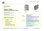
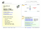
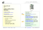
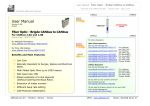
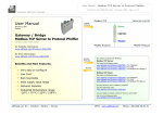
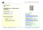
1
User Manual
CANopen to Modbus RTU Slave
Document code: MN67002_ENG
Revision 2.000
Page 1 of 24
Industrial Electronic Devices
User Manual
Logical
Scheme
Modbus RTU
RS485 / RS232
Slave
(*)
(**)
Revision 2.000
English
HD67002
Gateway / Bridge
CANopen to Modbus RTU Slave
Master / Slave
CANopen
(Order Code: HD67002)
for Ethernet TCP/IP, See: www.adfweb.com?Product=HD67004
for ModBus, See: www.adfweb.com?Product=HD67002
(***) for other CANBus protocol, See: www.adfweb.com?Product=HD67001
(**)
for Price information:
www.adfweb.com?Price=HD67002
For others Gateways / Bridges:
CANopen to Modbus
Similiar
Products
Benefits and Main Features:
Low Cost
Master/Slave CANopen
Slave Modbus
Galvanic isolation
Industrial temperature range:
-30°C / 70°C (-22°F / 158°F)
(***)
(*)
for Website information:
www.adfweb.com?Product=HD67002
Very easy to configure
CANopen
Benefit
See also the following links:
www.adfweb.com?Product=HD67001 (Modbus RTU Master)
www.adfweb.com?Product=HD67004 (Modbus TCP Master)
www.adfweb.com?Product=HD67005 (Modbus TCP Slave)
For others Gateways / Bridges:
For CAN bus 2.0A and/or CAN bus 2.0B to Modbus
See also the following links:
www.adfweb.com?Product=HD67011
www.adfweb.com?Product=HD67012
www.adfweb.com?Product=HD67014
www.adfweb.com?Product=HD67015
(Modbus
(Modbus
(Modbus
(Modbus
RTU Slave)
RTU Master)
TCP Slave)
TCP Master)
Do you have an your customer protocol?
See the following links:
www.adfweb.com?Product=HD67003
Do you need to choose a device? do you want help?
Ask it to the following link:
www.adfweb.com?Cmd=helpme
ADFweb.com Srl – IT31010 – Mareno – Treviso
INFO: www.adfweb.com
Phone +39.0438.30.91.31
User Manual
CANopen to Modbus RTU Slave
Document code: MN67002_ENG
Revision 2.000
Page 2 of 24
Industrial Electronic Devices
INDEX:
UPDATED DOCUMENTATION:
UPDATED DOCUMENTATION
REVISION LIST
WARNING
TRADEMARKS
INDEX
CHARACTERISTICS
CONNECTION SCHEME
CONFIGURATION
USE OF COMPOSITOR SW67002
NEW PROJECT / OPEN PROJECT
SET COMMUNICATION
SET SDO ACCESS
CONFIGURATION EMCY
CREATION OF AN EMCY
TRANSLATION OF AN EMCY FROM CANOPEN TO MODBUS
EXAMPLE OF FILTER SETTINGS FOR THE EMCY
SPECIFIC LIMITATION OF THE FILTER MASK
SUMMARY OF THE EMCY FILTER
DEFINITION EMCY WORD
SET OF TRANSLATE PDO
SET STORE PDO
SET TRANSMIT PDO
UPDATE DEVICE
CHARACTERISTICS OF THE CABLES
MECHANICAL DIMENSIONS
ORDER CODE
ACCESSORIES
WARRANTIES AND TECHNICAL SUPPORT
RETURN POLICY
PRODUCTS AND RELATED DOCUMENTS
ADFweb.com Srl – IT31010 – Mareno – Treviso
Page
2
2
2
2
2
3
4
6
6
7
8
9
12
13
13
14
15
16
17
19
19
20
21
22
23
23
23
24
24
24
Dear customer, we thank you for your attention and we remind you that you
need to check that the following document is:
Updated
Related to the product you own
To obtain the most recently updated document, note the “document code” that
appears at the top right-hand corner of each page of this document.
With this “Document Code” go to web page www.adfweb.com/download/ and
search for the corresponding code on the page. Click on the proper “Document
Code” and download the updates.
To obtain the updated documentation for the product that you own, note the
“Document Code” (Abbreviated written "Doc. Code" on the label on the product)
and download the updated from our web site www.adfweb.com/download/
REVISION LIST:
Revision
Date
1.000
1.005
1.006
1.100
2.000
09/07/2004
19/06/2005
22/06/2007
26/06/2007
05/06/2007
Author Chapter
Mt
Ddt
Av
Av
Av
All
All
All
All
All
Description
First release version
documentation code changed
Revision
Software changed
New document format
WARNING:
ADFweb.com reserves the right to change information in this manual about our
product without warning.
ADFweb.com is not responsible for any error this manual may contain.
TRADEMARKS:
All trademarks mentioned in this document belong to their respective owners.
INFO: www.adfweb.com
Phone +39.0438.30.91.31
User Manual
CANopen to Modbus RTU Slave
Document code: MN67002_ENG
Revision 2.000
Page 3 of 24
Industrial Electronic Devices
CHARACTERISTICS:
The Configurable CANopen Modbus RTU Slave Gateway allows the following:
two-directional information between networks CANopen and ModBUS
electrical isolation between two BUSes
to write SDO from ModBUS Word
to read SDO from ModBUS Word
to read EMCY from ModBUS Word
to read PDO from ModBUS Word
Communication Serial RS232/485
Temperature range -30°C to 70°C
The Gateway can be configured up to a maximum 1600 SDO.
While the maximum number of the following:
EMCY
EMCY Word
PDO
Store PDO
Depend on the available memory of the Gateway and the number defined SDO.
ADFweb.com Srl – IT31010 – Mareno – Treviso
INFO: www.adfweb.com
Phone +39.0438.30.91.31
User Manual
CANopen to Modbus RTU Slave
Document code: MN67002_ENG
Revision 2.000
Page 4 of 24
Industrial Electronic Devices
CONNECTION SCHEME:
Figure 1: Connection scheme of HD67002 between a CANopen and Modbus TCP
ADFweb.com Srl – IT31010 – Mareno – Treviso
INFO: www.adfweb.com
Phone +39.0438.30.91.31
User Manual
CANopen to Modbus RTU Slave
Document code: MN67002_ENG
Revision 2.000
Page 5 of 24
Industrial Electronic Devices
Figure 2: Connection Scheme for HD67002
ADFweb.com Srl – IT31010 – Mareno – Treviso
INFO: www.adfweb.com
Phone +39.0438.30.91.31
User Manual
CANopen to Modbus RTU Slave
Document code: MN67002_ENG
Revision 2.000
Page 6 of 24
Industrial Electronic Devices
CONFIGURATION:
The “Gateway CANopen to Modbus”, allows a CANopen network to
communicate with a Modbus network.
You need Compositor SW67002 software on your PC in order to
perform the following:
Define that the SDO of the CANopen are accessible from
Modbus.
Define how to update SDO in CANopen from Modbus.
Define that the EMCY of the CANopen are accessible from
Modbus.
Define how and which EMCY generated in CANopen can be
filtered.
Define which and how the PDO of CANopen are accessible
from Modbus.
Update the new configurations of the device.
Save, duplicate, modify, export the configurations.
USE OF COMPOSITOR SW67002:
To configure the Gateway, use the available software that runs with
Windows, called SW67002.
(The
SW67002
is
downloadable
on
the
site
http://www.adfweb.com/home/download/download.asp)
When launching the SW67002 the right window appears:
The following explains the function of the buttons:
ADFweb.com Srl – IT31010 – Mareno – Treviso
Figure 3: Main window for SW67002
INFO: www.adfweb.com
Phone +39.0438.30.91.31
User Manual
CANopen to Modbus RTU Slave
Document code: MN67002_ENG
Revision 2.000
Page 7 of 24
Industrial Electronic Devices
NEW PROJECT / OPEN PROJECT:
The “New Project” button creates the folder which contains the entire device configuration.
A device configuration can also be imported and exported:
To clone the configurations of a Programmable CANopen to Modbus Gateway in order to configure another device in the same manner, it
is necessary to maintain the folder and all its contents.
To clone a project in order to obtain a different version of the project, it is sufficient to duplicate the project folder with another name
and open the new folder with the button “Open Project”.
When a new project is created or an existent project is open, it will be possible to access the various configuration sections of the software:
“Set Communication”
“Set SDO Access”
“Set Translate EMCY”
Otherwise the Define EMCY Word
“Set Translate PDO”
Otherwise the Define Store PDO
ADFweb.com Srl – IT31010 – Mareno – Treviso
INFO: www.adfweb.com
Phone +39.0438.30.91.31
User Manual
CANopen to Modbus RTU Slave
Document code: MN67002_ENG
Revision 2.000
Page 8 of 24
Industrial Electronic Devices
SET COMMUNICATION:
This section defines the fundamental communication parameters of two Buses, CANopen and Modbus.
By pressing the “Set Communication” button from the main window for SW67002 (Fig. 3) the window
“Set communication” appears (Fig. 4):
In the fields “DevID”, the Gateway address is defined in the respective CANopen and Modbus;
In the fields “Baud Rate”, the velocity of the two Buses are defined;
The check box “Set Operational State at Start-Up” is used to set the operational state of the device
at start-up;
The check box “Network Start at Start-Up” is used to send the command of the operational to the
CANopen Network (i.e. when the device start up sen at Modbus Network a command and all device
is in operational);
The check box “Can Start on Modbus Command” is used for send the Modbus command
(sender word) of Operational/Pre-Operational State to one or all devices in CAN network.
o The sender word must have:
The high byte with the value of 1 for Operational or 2 for Pre-Operational.
The low byte must have the address of the device that is commanded to do the action
(Operational/PreOperational)
• Example if you want to set the state of Operational to the device canopen with
address 3, You must write the word “259” in the field “Add. Word Modbus”.
Note: 257=0x01.11.
If the field “Add. Word Modbus” you can set 0, then this action commands all the
devices.
The Gateway has two alternative for PDO: 15RPDO and 3RPDO or 8 RPDO and 8 TPDO. Select the
desired choice.
The Gateway has two alternative outlets from the Modbus side: RS485 or RS232. Select the
desired choice;
In the field “Parity”, the serial parity is defined;
“SDO Timeout” is the maximum time that the device attends for the answer from the Slave
interrogated;
Data bits and Stop bits, are a serial parameter and they are fixed in order at 8 and 1 for default.
ADFweb.com Srl – IT31010 – Mareno – Treviso
INFO: www.adfweb.com
Figure 4: “Set communication” window
Phone +39.0438.30.91.31
User Manual
CANopen to Modbus RTU Slave
Document code: MN67002_ENG
Revision 2.000
Page 9 of 24
Industrial Electronic Devices
SET SDO ACCESS:
Section “Set SDO Access”
The following objects can be defined within the section “Set SDO Access”:
the SDO of the CANopen are accessible from a word ModBUS.
Which word of the ModBUS are accessible from a SDO of the
CANopen.
By pressing the “Set SDO Access” button from the Main Window for
SW67002 (Fig. 3)
the window “SDO” appears (Fig. 5).
The data of the columns have the following meanings:
Figure 5: “SDO” window
In the field “Addr Word” insert the address of the SDO that supports the ModBUS word;
In the field “Hi Word” insert the correspondence between the high byte of the ModBUS word and a SDO byte
(note: its number can be 0, 1, 2, 3, 4)
o 1 = First byte of the SDO;
o 2 = Second byte of the SDO;
o 3 = Third byte of the SDO;
o 4 = Fourth byte of the SDO;
o 0 = No byte.
In the field “Lo word” insert the correspondence between the low byte of the ModBUS word and a SDO byte
(note: its number can be 0, 1, 2, 3, 4)
o 1 = First byte of the SDO;
o 2 = Second byte of the SDO;
o 3 = Third byte of the SDO;
o 4 = Fourth byte of the SDO;
o 0 = No byte.
In the field “R/W” insert number “0” if the SDO is only in reading or insert number “1” if the SDO is also in writing;
In the field “ID” insert the address of the CANopen device;
In the fields ”index”, “SubIndex” are the coordinates of the SDO in the CANopen;
In the field “nbyte” indicates the length of the SDO.
ADFweb.com Srl – IT31010 – Mareno – Treviso
INFO: www.adfweb.com
Phone +39.0438.30.91.31
User Manual
CANopen to Modbus RTU Slave
Document code: MN67002_ENG
Revision 2.000
Page 10 of 24
Industrial Electronic Devices
Example 1:
If you want to write data in the form of SDO in the CANopen
from the ModBUS network on the device at the address:
Address 16
Index 0x2003
Subindex 0
SDO Byte2
By dimensions 2 bytes
SDO Byte3
By the following word ModBUS
SDO Byte4
SDO Byte1
SDO Byte1
Hi word
High Byte
Word Modbus
Lo Word
Low Byte
Word Modbus
SDO Byte2
SDO Byte3
SDO Byte4
Addr Word 3000
Figure 6: Scheme of the word configuration
In the above scenario (Fig 5):
The Modbus master can read or write (note RW=1):
to the address of the ModBUS side Gateway slave (note
the one specified in the “Set communication”)
to the word ModBUS 3000 (note: Addr word 3000)
the first byte of the SDO found in the low byte of the
ModBUS word (note: Lo Word=1)
the second byte of the SDO found in high byte of the
ModBUS word (note: Hi Word=2)
ADFweb.com Srl – IT31010 – Mareno – Treviso
INFO: www.adfweb.com
Phone +39.0438.30.91.31
User Manual
CANopen to Modbus RTU Slave
Document code: MN67002_ENG
Revision 2.000
Page 11 of 24
Industrial Electronic Devices
The SDO:
two byte dimension (note: nByte=2)
belonging to a CANopen device ID 16 (note: ID=16)
of the following coordinates: Index 2003 and Subindex 0
Figure 7: Chart of SDO request from Modbus side.
ADFweb.com Srl – IT31010 – Mareno – Treviso
INFO: www.adfweb.com
Phone +39.0438.30.91.31
User Manual
CANopen to Modbus RTU Slave
Document code: MN67002_ENG
Revision 2.000
Page 12 of 24
Industrial Electronic Devices
CONFIGURATION EMCY:
By pressing the “Set Translate EMCY” button from the Main
Window for SW67002 (Fig. 3)
The window “Set Translate EMCY” appears (Fig. 8):
Below a figure to exemplification (Fig. 9):
Figure 9: Chart of diffused EMCY in Modbus from CANopen.
ADFweb.com Srl – IT31010 – Mareno – Treviso
Figure 8: “Set Translate EMCY” window
INFO: www.adfweb.com
Phone +39.0438.30.91.31
User Manual
CANopen to Modbus RTU Slave
Document code: MN67002_ENG
Revision 2.000
Page 13 of 24
Industrial Electronic Devices
CREATION OF AN EMCY:
Packet CAN of the EMCY. How it result from
registers structure (see left)
In order to intercept the EMCY of a device, it is necessary to
first define the EMCY and then fill in the window “SET Translate
EMCY” as desidered.
Use the button “New EMCY” to define a new EMCY.
COB
DEFINING STRUCTURE OF THE EMCY REGISTERS:
Reg. Description
1
2
3
4
5
6
ID
Error_code
Error_reg
Manu1
Manu2
Manu3
Filter Mask
Gateway
ID_EMCY
Mask_Error_Code
Mask_Error_Reg
Mask_Manu1
Mask_Manu2
Mask_Manu3
ID of the propagation device
BYTE 1 = Error_code
(Low)
BYTE 2 = Error_code
(hight)
BYTE 3 = Error_reg
Dimension
Register
7 bit
16 bit
8 bit
16 bit
16 bit
8 bit
BYTE 4 = Manu 1 (Low)
BYTE 5 = Manu 1 (hight)
BYTE 6 = Manu 2 (Low)
BYTE 7 = Manu 2 (hight)
BYTE 8 = Manu 3
TRANSLATION OF AN EMCY FROM CANOPEN TO MODBUS:
In order to intercept the EMCY of the device, it is necessary:
push the “New EMCY” button at the bottom of the window, “SET Translate EMCY” .
complete the field “ID_EMCY” with the CANopen device address whose EMCY you wish to intercept.
Put the following zero values in the fields:
“Enable_Mask_Error_Code” = 0,
“Enable_Mask_Error_Reg”= 0,
“Enable_Mask_Manu1” = 0,
“Enable_Mask_Manu2” = 0,
“Enable_Mask_Manu3”= 0,
These operations enables the Gateway:
to intercept all the EMCY coming from devices with the specific address from “ID EMCY” in the CANopen BUS.
And the possibility to register the EMCY in a word on the ModBUS side of the Gateway.
ADFweb.com Srl – IT31010 – Mareno – Treviso
INFO: www.adfweb.com
Phone +39.0438.30.91.31
User Manual
CANopen to Modbus RTU Slave
Document code: MN67002_ENG
Revision 2.000
Page 14 of 24
Industrial Electronic Devices
EXAMPLE OF FILTER SETTINGS FOR THE EMCY:
ACTION:
The device of the ID 10 BUS generates an EMCY. The Gateway individualizes and memorizes it in a ModBUS Word.
CONSEQUENCE:
The Gateway (ID 27 on the ModBUS) verifies the set conditions on the window “Define EMCY word”. Then it memorizes part of the EMCY
coming from the CANopen BUS in a readable word from the ModBUS.
EXAMPLE OF THE CONDITION:
The translation must be done when the ERROR CODE register of the generated EMCY takes the value, for example = 0x0B15.
In this case, the message must be translated from CANopen BUS where it is available under the form of ModBUS Word (Note: the filter
functions therefore in all other cases).
Therefore:
(see EMCY structure and the corresponded CAN Package)
“Error Code”= 0x0B15
Means when:
Byte1 = 00001011 Byte2 = 00010101,
In this case the following fields are inserted in the window “SET Translate EMCY”:
ID_EMCY = 10
Mask_Error_Code = 0x0B15
Enable_Mask_Error_Code (1111111111111111) (All the BITS of Error Code will be examined).
(0000101100010101)
(Note: the window “SET Translate EMCY” accepts decimal and hexadecimal values in the format with the prefix “0x” or “$”).
ADFweb.com Srl – IT31010 – Mareno – Treviso
INFO: www.adfweb.com
Phone +39.0438.30.91.31
User Manual
CANopen to Modbus RTU Slave
Document code: MN67002_ENG
Revision 2.000
Page 15 of 24
Industrial Electronic Devices
SPECIFIC LIMITATION OF THE FILTER MASK:
ACTION:
We want the EMCY to translate if:
Its “Error Code“ Register has the value 0x007C or
Its “Error Code” Register has the value 0x0063, or
Its “Error Code” Register has the value 0x0062
(Note: the OR operations in all above conditions)
CONSEQUENCE:
The Gateway can transmit the EMCY only with values that raise the same bits, but in this case the messages also transmits with other
specific conditions.
MOTIVE:
1° valore di Error_Code per traslare EMCY
2° valore di Error_Code per traslare EMCY
3° valore di Error_Code per traslare EMCY
0x007B = 0000 0000 0111 1011
0x0063 = 0000 0000 0110 0011
0x0062 = 0000 0000 0110 0010
Enable_Mask_Error_Code to activate the comparison
Mask_Error_Code to compare
1111 1111 1110 0110
0000 0000 0110 0110
The Mask must be calculated by doing the operations NOT XOR BIT to BIT of all values to
be intercepted.
Instead, the activation must be calculated by doing the operations AND BIT to BIT of all
values to be intercepted..
And so all the EMCY that will have the following “ERROR CODE” values, they will transmit.
ADFweb.com Srl – IT31010 – Mareno – Treviso
INFO: www.adfweb.com
0x0062
0x0063
0x006A
0x006B
0x0072
0x0073
0x007A
0x007B
=
=
=
=
=
=
=
=
0000
0000
0000
0000
0000
0000
0000
0000
0000
0000
0000
0000
0000
0000
0000
0000
0110
0110
0110
0110
0111
0111
0111
0111
0010
0011
1010
1011
0010
0011
1010
1011
Note how the BITS that are
undetermined, create the extra EMCY
values.
Phone +39.0438.30.91.31
User Manual
CANopen to Modbus RTU Slave
Document code: MN67002_ENG
Revision 2.000
Page 16 of 24
Industrial Electronic Devices
SUMMARY OF THE EMCY FILTER:
The EMCY generated by the device and the respective filter for Gateway are composed of the following:
5 Registers (Error_Code, Error_Reg, Manu1, Manu2, Manu3 respectively 16, 8, 16, 16; 8 BIT).
5 masks used to compare the 5 registers, of course, of the same dimension in BITS as the registers (respectively mask_eq_ec,
mask_eq_er, mask_eq_m1, mask_eq_m2, mask_eq_m3 )
5 activations BIT to BIT of the masks ((Enable_Mask_Error_Code, Enable_Mask_Error_Reg, Enable_Mask_Manu1,
Enable_Mask_Manu2, Enable_Mask_Manu3, respectively 16, 8, 16, 16; 8 BIT)
CONSIDERATIONS:
When all BITS of all activation registers are at zero, all EMCY are transmitted by the filter, because there is not a single BIT that actives the
comparison (BIT to 1). This is true for any value of entering data (5 EMCY registers generated) and for any mask value.
CONFIGURATIONS EMCY WORD:
Section “Define EMCY Word”
THE ROLE:
We mentioned that an EMCY from BUS A can pass (filter permitting) to BUS B. In this case on the ModBUS Side.
NECESSITY:
After having transmitted the filter coming from CANopen, an EMCY remains available on the MosBUS Side of the Gateway. Therefore any
ModBUS device can verify the EMCY conditions.
SOLUTION:
The Gateway acts as SDO server for the ModBUS.
The EMCY coming from CANopen gets reduced in a ModBUS word dimension of two bytes.
ADFweb.com Srl – IT31010 – Mareno – Treviso
INFO: www.adfweb.com
Phone +39.0438.30.91.31
User Manual
CANopen to Modbus RTU Slave
Document code: MN67002_ENG
Revision 2.000
Page 17 of 24
Industrial Electronic Devices
DEFINITIONS OF A EMCY WORD:
By pressing the “Define EMCY word” button from the Main Window for
SW67002 (Fig. 3)
the window “EWMCY” appears (Fig. 10):
Steps for the definition of an EMCY Word:
to create a word, use the “New “ button in the window “Define
EMCY Word”
In the fields “Index SDO BUS B” and “SubIndex SDO BUS B”,
insert the coordinates of the SDO of the BUS B, where it is
possible for the BUS B device to access a part of the last EMCY
which came from a particular device of BUS A
In the field “ID EMCY BUS A” the ID of the device that generates
the EMCY of BUS A is inserted
Now write each of the 16 BITS of the EMCY Word.
Writing the 16 BITS of the EMCY WORD:
Each EMCY Word is composed of the 16 BITS. Each bit is obtained by
using the masks provided by the EMCY package. (Note: see the above
structure of the EMCY package)
Mask1 (Range 0..255)
Pointer1 (Range 0.. 8)
Mask2 (Range 0 ..255)
Pointer2 (Range 0..8)
Figure 10: “EWMCY” window
ADFweb.com Srl – IT31010 – Mareno – Treviso
INFO: www.adfweb.com
Phone +39.0438.30.91.31
User Manual
CANopen to Modbus RTU Slave
Document code: MN67002_ENG
Revision 2.000
Page 18 of 24
Industrial Electronic Devices
The pointers 1 and 2 indicated which byte of the entering EMCY is
to be examined.
The selected bytes by the pointers are put in AND with their
respective masks.
The 0 or 1 result gets inserted in to the defined EMCY Word in the
established binary position
Packet EMCY that was generated in
the CAN
COB
ID
10
BYTE 1 = Error_Code
Pointer1_BIT4 = 2
BYTE 2 = Error_Code
(Byte n°2)
BYTE 3 = Error_reg
Pointer2_BIT4 = 6
BYTE 4 = Manu 1
(Byte n°6)
BYTE 5 = Manu 1
BYTE 6 = Manu 2
BYTE 7 = Manu 2
BYTE 8 = Manu 3
BYTE 2 = Error_Code (LW)
AND
EMCY Word: how it is available in
the ModBUS
Mask1_BIT4
AND
BYTE 6 = Manu 2 (HI)
AND
Mask2_BIT4
=
1/0
NOTE:
if Pointer 1 >< 0 and Pointer 2 >< 0 and if only are true the following condition:
Mask 1 == data that is indicated from Pointer 1 and
Mask 2 == data that is indicated from Pointer 2.
Because the bit is set to 1 in the EMCY Word
1
2
3
4
5
6
7
8
9
10
BIT MAP of the selected EMCY Word
ADFweb.com Srl – IT31010 – Mareno – Treviso
……
16
if Pointer 1 >< 0 and Pointer 2 == 0 is sufficient that the following condition is true:
Mask 1 == data that is indicated from Pointer 1
Because the bit is set to 1 in the EMCY Word.
if Pointer 1 == 0 and Pointer 2 == 0 follows that the bit isn't set to 1 in the EMCY word
INFO: www.adfweb.com
Phone +39.0438.30.91.31
User Manual
CANopen to Modbus RTU Slave
Document code: MN67002_ENG
Revision 2.000
Page 19 of 24
Industrial Electronic Devices
SET TRANSLATE PDO:
By pressing the “Set Translate PDO” button from the Main Window for
SW67002 (Fig. 3)
the window “RPDO” appears (Fig. 11):
User who have to memorize a PDO from CAN open to Modbus needs to
insert the coordinates of the PDO to be transmitted in the field “SET
Translate PDO” of the window.
In the field “cobid” insert the Cob_ID of the original PDO
In the field “id_dev_ori” insert the address of the original
device of BUS A (note: an alias can be inserted in the field
instead of the actual address of the PDO generator)
In the field “dimension” insert the number of byte of PDO
Figure 11: “RPDO” window
SET STORE PDO:
By pressing the “Define store PDO” button from the Main Window for
SW67002 (Fig. 3)
the window “INFOPDO” appears (Fig. 12):
Figure 12: “INFOPDO” window
ADFweb.com Srl – IT31010 – Mareno – Treviso
INFO: www.adfweb.com
Phone +39.0438.30.91.31
User Manual
CANopen to Modbus RTU Slave
Document code: MN67002_ENG
Revision 2.000
Page 20 of 24
Industrial Electronic Devices
SET TRANSMIT PDO:
It is possible to write the PDOs using the Preset Multiple
Registers Function (Modbus function 16).You have to write
all the modbus register (that rapresent the PDO Data)
with one modbus command.
By pressing “Set Transmit PDO” button the window
“Transmit PDO” appears:
User who have to write a PDO from Modbus to CANopen
needs to insert the coordinates of the PDO to be
transmitted in the field “SET Transmit PDO” of the
window.
In the field “COB-ID” insert the COB-ID of the
PDO;
In the field “Dimension” insert the number of
byte of PDO;
In the field “Stert Modbus Address” insert
the number of modbus register that would you
like start for writing the PDO.
Figure 13: “Transmit PDO” window
ADFweb.com Srl – IT31010 – Mareno – Treviso
INFO: www.adfweb.com
Phone +39.0438.30.91.31
User Manual
CANopen to Modbus RTU Slave
Document code: MN67002_ENG
Revision 2.000
Page 21 of 24
Industrial Electronic Devices
UPDATE DEVICE:
Section “UP Date Device”:
Insert the boot jumper, see figure 2.
In order to load the parameters after they are set, set the com port you
used for update, you must click the button “execute update firmware”
on the principal window.
Figure 14: Update
device procedure.
ADFweb.com Srl – IT31010 – Mareno – Treviso
INFO: www.adfweb.com
Phone +39.0438.30.91.31
User Manual
CANopen to Modbus RTU Slave
Document code: MN67002_ENG
Revision 2.000
Page 22 of 24
Industrial Electronic Devices
CHARACTERISTICS OF THE CABLES:
The connection from RS232 socket to a serial port (example one from a personal computer), must be made with a Null Modem cable (a
serial cable where the pins 2 and 3 are crossed).
It is recommended that the RS232 Cable not exceed 15 meters.
The connection at RS485 socket must be done with twisted and shielded cable.
The terminal resistor must be inserted when the HD67102 is at the end of the line, using the Terminator jumper.
Can bus cable characteristics:
DC parameter:
Impedance
70
AC parameters:
Impedance
120
Length
Ohm/m
Ohm/m
delay
5 ns/m
Baud Rate [bps]
Length MAX [m]
10 K
5000
20 K
2500
50 K
1000
100 K
650
125 K
500
250 K
250
500 K
100
800 K
50
1000 K
25
ADFweb.com Srl – IT31010 – Mareno – Treviso
INFO: www.adfweb.com
Phone +39.0438.30.91.31
User Manual
CANopen to Modbus RTU Slave
Document code: MN67002_ENG
Revision 2.000
Page 23 of 24
Industrial Electronic Devices
MECHANICAL DIMENSIONS:
Figure 15: Mechanical dimensions scheme
ORDER CODE:
Order Code: HD67002
-
Gateway – CANopen to Modbus RTU Slave
Order Code: AC34107
-
Null Modem Cable Fem/Fem DSub 9 Pin 1,5 m
Order Code: AC34114
-
Null Modem Cable Fem/Fem DSub 9 Pin 5 m
Order Code: AC34001
-
Rail DIN - Power Supply 220/240V AC 50/60Hz – 12 V AC
Order Code: AC34002
-
Rail DIN - Power Supply 110V AC 50/60Hz – 12 V AC
ACCESSORIES:
ADFweb.com Srl – IT31010 – Mareno – Treviso
INFO: www.adfweb.com
Phone +39.0438.30.91.31
User Manual
CANopen to Modbus RTU Slave
Document code: MN67002_ENG
Revision 2.000
Page 24 of 24
Industrial Electronic Devices
WARRANTIES AND TECHNICAL SUPPORT:
For fast and easy technical support for your ADFweb.com SRL products, consult our internet support at www.adfweb.com.
Otherwise contact us at the address [email protected]
RETURN POLICY:
If while using your product you have any problem and you wish to exchange or repair it, please do the following:
1)
Obtain a Product Return Number (PRN) from our internet support at www.adfweb.com. Together with the request, you need to provide detailed information about the
problem.
2)
Send the product to the address provided with the PRN, having prepaid the shipping costs (shipment costs billed to us will not be accepted).
If the product is within the warranty of twelve months, it will be repaired or exchanged and returned within three weeks. If the product is no longer under warranty, you will
receive a repair estimate.
PRODUCTS AND RELATED DOCUMENTS:
Part
Description
URL
HD67121
Gateway CANopen / Canopen
www.adfweb.com?product=HD67121
HD67001
Gateway CANopen / Modbus – RTU Master
www.adfweb.com?product=HD67001
HD67004
HD67005
Gateway CANopen / Modbus – Ethernet TCP
www.adfweb.com?product=HD67004
HD67134
Gateway CANopen / DeviceNet
www.adfweb.com?product=HD67134
HD67117
CAN bus Repeater
www.adfweb.com?product=HD67117
HD67216
CAN bus Analyzer
www.adfweb.com?product=HD67216
ADFweb.com Srl – IT31010 – Mareno – Treviso
INFO: www.adfweb.com
Phone +39.0438.30.91.31