1
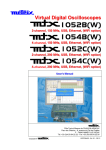
SCOPIX III
Portable Oscilloscopes
40MHz 2-channel OX 7042
60MHz 2-channel OX 7062
1 0 0 M H z 2 - c ha n n e l O X 7 1 0 2
100MHz 4-channel OX 7104
200MHz 2-channel OX 7202
200MHz 4-channel OX 7204
U
Usseerr’’ss M
Maannuuaall
Pôle Test et Mesure de CHAUVIN-ARNOUX
Parc des Glaisins - 6, avenue du Pré de Challes
F - 74940 ANNECY-LE-VIEUX
Tél. +33 (0)4.50.64.22.22 - Fax +33 (0)4.50.64.22.00
Copyright ©
X03535G02 - Ed. 1 - 05/14
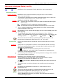
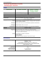
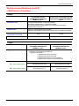
General Instructions
Attention !
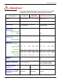
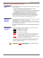
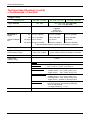
This is the SCOPIX III Oscilloscope user’s manual. It also applies
to SCOPIX I and II Oscilloscopes, with following restrictions :
SCOPIX II,
except OX 720x
SCOPIX I
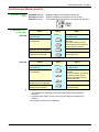
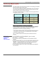
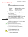
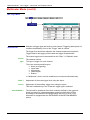
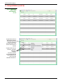
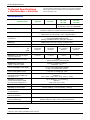
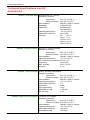
Characteristics
SCOPIX III and OX 720x
Screen
LCD 5,7’’ STN
LCD 5,7’’ TFT
SD card reader
no
yes
HX0084 cable
the acceptable max. speed is
115.200 bauds
the acceptable max. speed is
460.800 bauds
no
yes
no
yes
Oscilloscope :
Trigger menu
Trigger threshold
option
Oscilloscope :
Display menu
Cumulate option
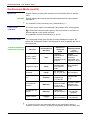
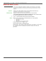
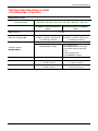
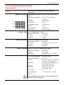
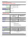
Multimeter :
technical specifications
DC
measure range
Resolution
AC and AC+DC
measure range
Resolution
0.4V
4V
40V
400V 800V 0.8V
0.1mV 1mV
10mV
0.1V
0.1V
0.3V
30V
300V
600V 0.6V
3V
0.1mV 1mV
10 mV 0.1V
1V
8V
0.1mV 1mV
6V
0.1mV 1mV
80V
800V
10mV
0.1V
60V
600V
10mV
0.1V
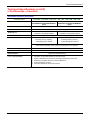
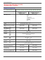
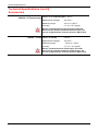
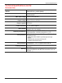
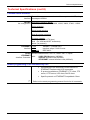
Multimeter :
Trigger
no
yes
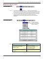
Access to internal files
through FTP from a PC
ftp://<IP address>/
ftp://<IP address>/RAM:
ftp://<IP address>/CARD:
Access to external
FTP server
no
yes
yes
impossible
impossible
possible
Viewing of GIF and BMP
files from a screen grab
(hardcopy)
SCOPIX
General Instructions
Contents
General instructions
Description of the instrument
Chapter I
General ................................................................................................... 3
Software updating................................................................................. 7
Chapter II
Presentation ......................................................................................... 9
Views .................................................................................................... 10
Terminal Boards .................................................................................. 11
Activation ............................................................................................. 16
Battery .................................................................................................. 17
Using the menus ................................................................................. 19
Network ................................................................................................ 19
Micro SD Card ..................................................................................... 23
Description of Accessories
Chapter III
HX0061 ............................................................................................... 28
HX0063 ............................................................................................... 28
PROBIX ............................................................................................... 29
HX0030 .................................................................................. 30
HX0031 .................................................................................. 31
HX0032 .................................................................................. 32
HX0033 .................................................................................. 33
HX0034 .................................................................................. 34
HX0035 .................................................................................. 35
HX0036 .................................................................................. 36
HX0072 .................................................................................. 37
HX0073 .................................................................................. 38
HX0093 .................................................................................. 39
HX0094 .................................................................................. 40
HX0095 .................................................................................. 41
HX0096 .................................................................................. 42
Recommendations for use ................................................................. 47
Oscilloscope Mode
Chapter IV
Keys ...................................................................................................... 49
Display ................................................................................................. 54
Menus
"Vertical" menu ................................. 61
"Trigger" menu ................................. 73
"Horizontal" menu ................................. 84
"Display" menu ................................. 89
"Measurement" menu ................................. 91
"Memory" menu ................................. 96
"Utilities" menu ................................. 99
"Help" menu ............................... 106
Multimeter Mode
Chapter V
Keys .................................................................................................... 109
Display ............................................................................................... 111
Menus ................................................................................................. 114
"Vertical" menu ............................... 115
"Trigger" menu ............................... 117
"Horizontal" menu ............................... 118
"Display" menu ............................... 118
"Measurement" menu ............................... 120
"Memory" menu ............................... 123
"Utilities" menu ............................... 123
"Help" menu ............................... 123
SCOPIX
I -1
General Instructions
Harmonic Analysis Mode
Recorder Mode
Chapter VI
Display ..................................................................................................... 125
Menus
"Vertical" menu ................................. 129
"Horizontal" menu ................................. 131
"Display" menu ................................. 132
"Measure" menu ................................. 132
"Memory" menu ................................. 133
"Utilities" menu ................................. 133
"Help" menu ................................. 133
Chapter VII
Keys ......................................................................................................... 135
Display ..................................................................................................... 138
Menus
"Vertical" menu ................................. 146
"Trigger" menu ................................. 147
"Horizontal" menu ................................. 152
"Display" menu ................................. 153
"Measurement" menu ................................. 155
"Memory" menu ................................. 156
" Utilities" menu ................................. 159
"Help" menu ................................. 161
HTTP and FTP Server
Chapitre VI
General .................................................................................................... 163
ScopeNet ................................................................................................. 164
ScopeAdmin ............................................................................................ 175
PolicyTool ............................................................................................... 178
FTP Server ............................................................................................... 179
Applications
Chapter IX
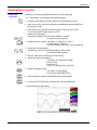
Display of the calibration signal ................................................................ 180
Automatic measurements ......................................................................... 183
Cursor measurements .............................................................................. 183
Phase offset measurement with cursor .................................................... 183
Automatic phase measurement ................................................................ 183
Manual phase measurement .................................................................... 184
Videosignal display ................................................................................... 184
Examination of a specific TV line .............................................................. 186
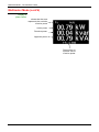
Automatic measurement in “Harmonic Analysis” Mode ............................ 187
“ROLL” Mode display of slow phenomena ............................................... 189
Min/Max Acquisition .................................................................................. 190
Measurement in “Multimeter” Mode ......................................................... 192
Measurement in “Recorder” Mode ........................................................... 193
ETHERNET network application examples .............................................. 197
File transfer .............................................................................................. 197
Hard copy on network printer ................................................................... 198
Installation of a FTP server ...................................................................... 199
”Virtual Printers” ....................................................................................... 203
Technical Characteristics
Chapter X
Specifications .............................................................................. 209 to 228
General & Mechanical Specifications
Chapter XI
Specifications ......................................................................................... 229
Supply
Chapter XII
Supply..................................................................................................... 230
Index
ADDENDUM
I-2
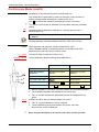
“Line Monitoring” Mode......................................................................... A-1
SCOPIX
General Instructions
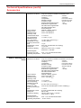
General Instructions
Introduction
Congratulations ! You have just purchased a portable digital oscilloscope.
Thank you for your trust in the quality of our products.
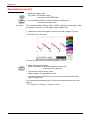
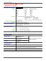
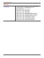
Here is the family of instruments to which it belongs:
SCOPIX III OX 7042
monochrom
2-channel
or color
40 MHz
2,5 GS/s sample
SCOPIX III OX 7062
monochrom
2-channel
or color
60 MHz
2,5 GS/s sample
SCOPIX III OX 7102 color
2-channel 100 MHz 2,5 GS/s sample
SCOPIX III OX 7104 color
4-channel 100 MHz 2,5 GS/s sample
SCOPIX III OX 7202 color
2-channel 200 MHz 2,5 GS/s sample
SCOPIX III OX 7204 color
4-channel 200 MHz 2,5 GS/s sample
*
All instruments in this range are equipped with Micro SD card.
This oscilloscope also offers the following modes:
• Multimeter mode
• Harmonic Analyser mode (option)
• Recorder mode (option)
• Other possible options, see p. 7 Æ Check our website regularly.
It complies with safety standard NF EN 61010-1 + NF EN 61010-2-30,
double insulation, relative to electronic measuring instruments.
For optimum service, read this manual carefully and comply with the
operating precautions.
Non-compliance with the warnings and/or operating instructions might
damage the instrument and/or its components and could prove dangerous
for the user.
Precautions and
safety measures
• This instrument has been designed for use:
- indoors
- in an environment with pollution level 2,
- at an altitude of less than 2000 m,
- at a temperature between 0°C and 40°C,
- with relative humidity of less than 80% up to 31°C.
• The safety of any system integrating the apparatus concerns the
responsibility of the assembler of the system.
• It can be used for measurements on circuits 600V CAT III, 1000V CAT II
in relation to earth and can be powered by a 98 Vrms to 264Vrms 300V
CAT II mains network, with an external power supply. However, some
accessories can lead you to use this instrument on circuits of lower
voltage and category.
Conform the given values when connecting the accessory.
SCOPIX
I-1
General Instructions
General Instructions (cont’d)
Precautions and
safety measures
(cont’d)
before use
• Comply with environmental and storage conditions.
• Check the integrity of the protections and insulation of the accessories.
Any item of which the insulation is deteriorated (even partially) must be
taken out of service and scrapped. A change in the colour of the
insulation is a sign of deterioration.
• External power supply : it must be connected to the instrument and to the
mains network (from 98 VAC to 264 VAC, 300V CAT II). Make sure that it
is in good working conditions.
• Removable line/power cords must not be replaced by cords having
unsuitable rated characteristics.
during use
• Read carefully all the notes preceded by the symbol
.
• The instrument power supply is equipped with an electronic protection
system which is reset automatically when the fault is eliminated.
• Be sure not to obstruct the ventilation holes.
• As a safety measure, use only suitable cords and accessories supplied
with the instrument or approved by the manufacturer.
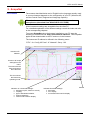
Definition of
measurement
categories
*
I-2
Overvoltage category ll is for equipment intended to be supplied from the
building wiring. It applies both to plug-connected equipment and to
permanently connected equipment.
E.g.: Measurements on the network circuits of household appliances,
portable tools and other similar appliances.
Overvoltage category lll is for equipment intended to form part of a
building wiring installation. Such equipment includes socket outlets, fuse
panels, and some mains installation control equipment.
E.g. Measurements on distribution panels (including secondary meters),
circuit breakers, cabling including cables, busbars, junction boxes,
disconnecting switches, power outlets in the fixed installation, and industrial
appliances and other equipment, such as motors permanently connected to
the fixed installation
Overvoltage category lV is for equipment installed at or near the origin of
the electrical supply to a building, between the building entrance and the
main distribution board. Such equipment may include electricity tariff meters
and primary overcurrent protection devices.
E.g.: Measurements on systems installed before the main fuse or the circuit
breaker of the building's installation.
Using a measuring device, a lead, or an accessory of a lower measurement
category or voltage reduces the whole system (device + leads + accessories) t
the lowest measurement category and/or service voltage.
SCOPIX
General Instructions
General Instructions (cont'd)
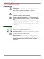
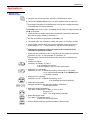
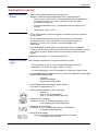
Symbols used on
the instrument
Risk of electric shocks: input connection and disconnection instructions. Always
connect the sensors or adapters to the instrument before connecting them to the
measuring points. Always disconnect the sensors or cables from the
measurement points before disconnecting them from the instrument. These
instructions apply before cleaning the instrument and before opening the battery
housing cover and the sensor calibration outputs.
Warning: Risk of danger. The operator undertakes to consult the instructions
each time this danger symbol is encountered.
Application or withdrawal not authorized for non-insulated conductors
carrying dangerous voltage levels.
Dual insulation
Earth
Frame or chassis terminal
In the European Union, this product is the subject of selective waste sorting for
the recycling of electric and electronic equipment in compliance with the
Directive WEEE 2002/96/CE: this equipment must not be considered as
household waste. The spent batteries and accumulators must not be treated
as household waste. Return them to the appropriate collection point for
recycling.
This CE marking indicates compliance with the European "Low Voltage" and
"Electromagnetic compatibility" directives (73/23/EEC and 89/336/EEC).
This product or this packaging is recyclable.
SCOPIX
I-3
General Instructions
General Instructions (cont'd)
Warranty
This equipment is guaranteed for 3 years against any defect in materials or
workmanship, in accordance with the general terms and conditions of sale.
It can only be repaired by the manufacturer. The manufacturer reserves the
right to carry out repair or replacement of all or part of the equipment. If the
equipment is returned to the manufacturer, initial transport costs shall be
borne by the customer.
The warranty does not apply following:
• unsuitable use of the equipment or use with other incompatible
equipment
• modification of the equipment without explicit authorization from the
manufacturer’s technical services
• repair carried out by a person not certified by the manufacturer
• adaptation to a specific application, not provided for in the definition of
the equipment or by the operating manual
• an impact, a fall or a flooding.
Maintenance and
metrological
verification
Before the equipment is opened, it must be disconnected from the mains
supply and the measurement circuits, and the operator must not become
charged with any static electricity. This could cause the destruction of
internal parts.
Any adjustment, servicing or repair of the unit under power must be
undertaken only by qualified personnel, after reading the instructions in this
manual.
A qualified person is a person who is familiar with the installation, its
construction, its use and the hazards that exist. They are authorized to
activate and deactivate the installation and equipment, in compliance with
the safety instructions.
As for all surveying equipment, yearly metrological checks are necessary.
These checks can also be done as part of preventative maintenance.
Information and contact details : contact your nearest distributor.
Unpacking Repacking
All the equipment was verified mechanically and electrically before
shipping.
When you receive it, carry out a quick check to detect any damage that
may have occurred during transport. If necessary, contact our sales
department immediately and register any legal reservations with the carrier.
In the event of reshipping, it is preferable to use the original package.
Indicate the reasons for the return as clearly as possible in a note attached
to the equipment.
Repair
I-4
For all repairs before or after expiry of warranty, please return the device to
your distributor.
SCOPIX
General Instructions
General instructions (cont'd)
Cleaning
• Turn the instrument off.
• Clean it with a damp cloth and soap.
• Never use abrasive products or solvents.
• Allow to dry before any further use.
Verifying the proper operation of equipment
A self-test operation is performed by the instrument when starting. If a
problem is detected, an error message with a numeric code is displayed on
the screen.
The result of this self-test is also available in the menu "Util Æ system."
We recommend an annual check of your instrument by an accredited
metrology service (refer to your nearest distributor).
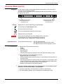
Update the instrument's internal software
• Log on to the www.chauvin-arnoux.com website.
• In the "Support" section, select "Download Center".
• Download the "firmware" corresponding to your instrument model.
• Also download the installation instructions for this firmware.
• Refer to these instructions to update your instrument.
Firmware update :
You may use PC software provided on the CD_ROM and consult Internet site
www.chauvin-arnoux.com
SCOPIX
I-5
General Instructions
I-6
SCOPIX
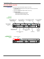
Description of the instrument
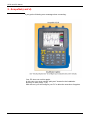
Description of the instrument
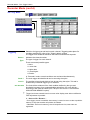
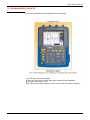
This manual describes the operation of an OX 7204 oscilloscope.
OX 7xx4 : the adjustment of the 4 channels is accessible by the opposite keys.
OX7xx2 : the adjustment of the 2 channels is accessible by the opposite keys.
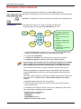
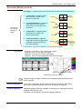
Presentation
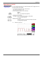
This instrument is part of our range of portable oscilloscopes.
Its special feature is that it groups 4 instruments into one:
FFT
function
Digital
Oscilloscope
Harmonic
Analyzer
Multimeter
OX 7042
OX 7062
OX 7102
OX 7104
OX 7202
OX 7204
• DC voltage measurement
• AC voltage measurement
(RMS)
• Current measurement for
clamps
Recorder
• Resistance measurement
• Condenser measurement
• Diode test
• Continuity test
• Temperature measurement
PT100 or TCK
• a digital oscilloscope for laboratory use, intended for the analysis of the
signals encountered in electronics and electrical engineering
• an 8,000-count multimeter
• a "harmonic" analyzer, for breaking down 4 signals (or 2) (option)
• a recorder, designed to capture single or slow signals (option)
All the channels are insulated from one another for measurements on 600V
CAT III, 1000V CAT II installations with appropriated PROBIX accessories
while complying with the standard NF EN 61010-1 + NF EN 61010-2-030.
The instrument works with a constant acquisition depth of 2500 counts.
Memory management is organized using a "Windows®"-type file system.
A large LCD screen is used to view the signals applied, along with all the
settings.
The main control functions are directly accessible using the keys on the front
panel and can be modified using a touch-sensitive pad with the stylus
supplied.
A graphical interface similar to a PC's is used to:
• select the advanced functions by means of drop-down menus and the
touch-sensitive pad
• act directly on the objects (curves, cursors, etc.) displayed on the screen.
This means that the settings can be modified.
This instrument is completed by :
USB via HX0084 adapter
ETHERNET
CENTRONICS (option)
RS232 via HX0042 cable (option)
SCOPIX
II - 9
Description of the instrument
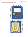
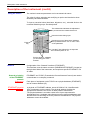
Description of the instrument (cont'd)
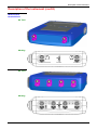
OX 7202
Front Panel
Rear Panel
II - 10
SCOPIX
Description of the instrument
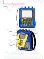
Description of the instrument (cont'd)
OX 7204
Front Panel
Rear Panel
Stylus
Strap
Fans
Stand
Cover of
the battery
pack
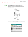
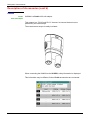
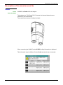
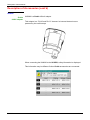
Using the stand
SCOPIX
The oscilloscope is equipped with a tilt-stand, allowing easy viewing while
placed on a benchtop.
II - 11
Description of the instrument
Description of the instrument (cont'd)
Markings on rear
panel
TO AVOID ELECTRICAL SHOCK
DISCONNECT LEADS, PROBES AND
POWER SUPPLY BEFORE REMOVING COVER
ONLY REPLACE WITH
9.6V NiMH CUSTOM PACK
II - 12
SCOPIX
Description of the instrument
Description of the instrument (cont'd)
Side view
Marking
Communication
Interfaces
« Wallplug »
power supply
input
« Micro SD-Card »
location
SCOPIX
Calibration
probe
II - 13
Description of the instrument
Description of the instrument (cont'd)
Measurement
terminal block
OX 7202
Marking
1
4
OX 7204
Marking
II - 14
SCOPIX
Description of the instrument
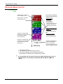
Description of the instrument (cont'd)
Front (description)
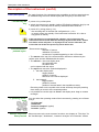
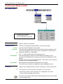
1 On/Standby/Off
key
The main functions of the instrument are accessible on the front panel and can
be modified using the touch-sensitive pad (with its stylus) or the menu bar.
• power on by a short press
• switch the instrument to standby (yellow LED flashing inside the key) by one
short press. A second press on the key reactivates the instrument.
• power off by a long press (> 3 s):
- the recording time of the files and configuration is < 15 s.
- In certain cases, the standby of the instrument is effective 45 s. after a
long press on this key.
If the instrument is not equipped with a battery, never disconnect the
instrument from the mains while the message "System shut down : Please
wait before switch off power" is displayed on the screen. Otherwise, the
current file and all the files previously saved will be lost.
1 touch-sensitive
pad and stylus
4 "operating mode"
keys
28 keys only active
when pressed
SCOPIX
These can be used for:
selection of menus,
validation of functions,
movement of symbols appearing on the LCD screen.
• The menus at the top of the screen and the submenus selected by the
pointer open and are validated with the stylus.
• The menus in the curve display area,
the command area
the status area
can be opened with the stylus.
• The stylus can move the symbols displayed in:
1. the main display area:
trigger position
position of cursors
reference of the traces displayed
2. the bargraph:
trigger position
position of cursors
position of zoomed area in the acquisition memory
Place the pointer on the symbol to be moved and keep the stylus pressing
down while you move it to the required position.
• It is possible to use the stylus to zoom in the display area: drag to create a
rectangle.
You can select the operating mode of the instrument by pressing one of these
4 keys:
"oscilloscope"
"multimeter"
"harmonic analyser" (option)
"recorder" (option)
Shortcut access to the most common functions: see chapter on "The Keys" for
the "Oscilloscope", "Multimeter", “Harmonic Analyser” and “Recorder” modes.
II - 15
Description of the instrument
Description of the instrument (cont'd)
The portable oscilloscopes in this range are designed to operate on a power
source delivering 98 to 264 V (ACrms) or in stand-alone mode with a battery.
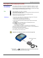
Initial operation of
the oscilloscope
The instruments are delivered with a mains adapter, an external power supply
(battery charger) and an Ni-MH battery (9.6 V ; 4 A/h).
Type: time delay, 2.5 A, 250 V, 5 x 20 mm
The external power supply is equipped with a protection fuse that must only be
replaced with an identical model.
Replacement must only be performed by qualified personnel.
Contact your nearest service centre.
Fuse
Starting up
• Connect the 4-point lead of the external power supply to the "'DC-Input"
socket located on the side of the oscilloscope.
*
Do not insert any metal objects into this lead.
• Connect the mains lead from the external power supply to the external
power supply.
The POWER LED on the adapter lights up, indicating that it is live.
The CHARGE LED flashes, indicating:
• the absence of the battery or
• slow charging of the battery, if it is present in the oscilloscope.
Press the instrument's ON switch: it lights on and then a clock is displayed on
the screen during the start-up sequence.
The message "Instrument start-up" is displayed.
The oscilloscope is then ready for use.
By default, the "Advanced" mode is not active (see page 106).
external power supply
*
II - 16
The symbol
in the display area for the current value means that
the instrument is connected to the mains supply.
SCOPIX
Description of the instrument
Description of the instrument (cont'd)
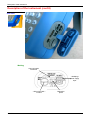
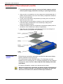
*
To prevent any electric shocks, remove the Probix adapters and the
external power supply lead before installing or replacing the battery.
•
Using a coin or a screwdriver, turn by a quarter turn (anticlockwise) the 2
plastic screws located on the cover of the battery compartment located at
the rear of the instrument
•
Lift the cover of the battery compartment by inserting the coin under the
slot at the top of the cover.
•
Then connect the 4-point battery connector to the connector located
inside the battery compartment of the oscilloscope, taking care to
respect the failsafe systems.
•
Position the battery inside the oscilloscope compartment (battery wires at
the bottom of the oscilloscope's battery compartment).
•
Close the cover of the battery compartment and lock it by turning the 2
plastic screws by one quarter turn (clockwise).
Screw
Cover
Battery
Battery
compartment
Lower
casing
Changing the
batterie
Follow the same procedure and make sure that the replacement battery
model is identical to the original one.
The oscilloscope contains a Ni-MH battery. The flat battery must be
handed over to a recycling firm or a company specialized in the treatment
of dangerous waste materials. Never dispose of the battery with other
solid waste.
For further information, contact your nearest service centre.
When the oscilloscope is delivered, the battery may be discharged and
require a complete recharge. Full charging of the battery will then take
about two and a half hours, with the oscilloscope switched off.
SCOPIX
II - 17
Description of the instrument
Description of the instrument (cont'd)
Charging the
battery
Once the battery is located in its compartment, follow the external power supply
start-up instructions.
*
•
To speed up recharging of the battery, switch off the power to the
oscilloscope by a long press on the ON/OFF button.
•
Battery fully discharged: during the first 10 minutes, the CHARGE LED of the
external power supply flashes, indicating that the battery is slow-charging.
The CHARGE LED then lights up when it switches to fast-charging.
During the loading of the battery (after 15 min), the startup of the
oscilloscope causes the premature stop of the load. It is possible to restart the loading while disconnecting, then reconnecting the charger.
The LED goes out when the battery is fully charged (approx. 2h30).
Charging the
battery while
using the
oscilloscope
When the oscilloscope is connected to the mains via the external power supply, it
is possible to perform slow-charging of the battery.
The CHARGE LED of the external power supply lights up. Full recharging of a
totally discharged battery then takes approx. five hours and a half. The LED goes
out when the battery is fully charged.
*
Powering the
instrument with
the battery
Frequently recharging a battery when it is not fully discharged reduces its
life span.
When the oscilloscope is powered by a battery, an charge status indicator is
included in the display area of the current value:
the battery is 100 % charged
the battery is 80 % charged
the battery is 60 % charged, etc.
this symbol indicates that there are only a few minutes more,
so you are advised to recharge it or switch to the mains supply.
The battery is totally flat and the screen is about to be
deactivated. You must either recharge the battery or connect the
instrument to the external power supply.
If you change battery, a complete battery charge and discharge cycle (until the
instrument is automatically deactivated when discharging has finished) is
essential to calibrate this indicator.
To maintain the battery in good condition, use the oscilloscope at least
until the level
before recharging.
II - 18
SCOPIX
Description of the instrument
Description of the instrument (cont'd)
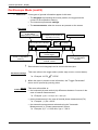
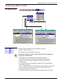
Using the menus
The various instrument parameters can be accessed via menus.
The rules for using, selecting and modifying an option are identical to those
defined by Microsoft Windows.
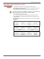
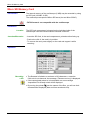
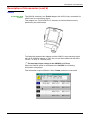
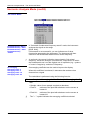
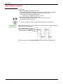
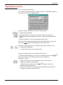
To input a numerical value (time base, alignment, etc.), a double click on the
numerical field brings up a virtual keyboard:
The window title indicates the adjustment
in process and the measurement unit
Numerical value being input
Pressing on one of these keys initialises
the input field with the min. or max. value
of the parameter
Erase
key
Use the E key followed by an exponent
to indicate a power of 10
Exit the window, validating
(or cancelling) the value
entered
Network
Configuration of the "Network" interface (ETHERNET).
This interface uses the same connector (USB/RS232/ETHERNET), located on
the right-hand side of the instrument, and requires a specific ETHERNET / RJ
45 cable.
General principles
of the ETHERNET
network
Addressing
ETHERNET and TCP/IP (Transmission Protocol/Internet Protocol) are used to
communicate on a company's network.
ETHERNET physical
addresses
A physical or ETHERNET address, stored in ROM or PAL, identifies each
item of equipment on the network. The physical address enables the
equipment to determine the source of data "packet" transmission.
The physical address is a number coded over 6 bytes represented in
hexadecimal form. Hardware manufacturers procure physical addresses and
allocate them incrementally when the product is manufactured. The physical
addresses cannot be modified.
SCOPIX
Each piece of equipment under TCP/IP has a physical address (ETHERNET)
and an Internet address (IP).
II - 19
Description of the instrument
Description of the instrument (cont'd)
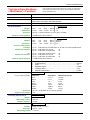
IP addresses
An IP address is coded over 4 bytes, displayed in decimal format.
(# Example: 132.147.250.10). Each field may be coded between 0 and 255
and is separated by a decimal point.
Unlike the physical address, the IP address can be modified by the user.
You must ensure that the IP address is unique on your network. If an
address is duplicated, network operation becomes random.
The IP address is made up of two parts:
• the network identifier (Network ID) identifying a given physical network
• the host identifier (Host ID) identifying a specific item of equipment on the
same network.
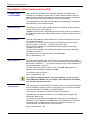
There are 5 addressing classes. Only classes A, B and C are used to identify
the equipment.
See below:
Class A
0XXXXXXX
XXXXXXXX
Network ID
XXXXXXXX
XXXXXXXX
Host ID
Class B
10XXXXXX
XXXXXXXX
XXXXXXXX
Network ID
XXXXXXXX
Host ID
Class C
010XXXXX
XXXXXXXX
Network ID
II - 20
XXXXXXXX
XXXXXXXX
Host ID
SCOPIX
Description of the instrument
Description of the instrument (cont'd)
SUBNET mask
and GATEWAY
If the result of the operation ' ET LOGIQUE' between IP address of the
recipient of the message and the value of subnet mask is different from the
address of the recipient of the message, this message is sent to the gateway
which will be given the responsibility to forward it to destination.
The programming of the mask and the address of the gateway is possible on
the instrument, in the Advanced mode.
DHCP Protocol
This protocol is used to automatically assign an IP address to the instrument
when it connects up to the network.
A DHCP (Dynamic Host Configuration protocol) server must be accessible on
this network (contact your network administrator to make sure that this server
is present).
FTP protocol
A file can be transferred quickly between a PC and the instrument using FTP
(File Transfer Protocol).
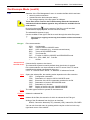
To use the "FTP Server" function, open your favourite browser on the PC
(Firefox, Explorer 7, Chrome, ...) and type in the URL field:
"ftp://192.168.3.1/RAM:" to access the internal file system of instrument
IP address 192.168.3.1
"ftp://192.168.3.1/CARD:" to access the file system of instrument SDCARD
IP address 192.168.3.1
The oscilloscope is can also be used as an FTP client.
See §. Applications p. 197.
HTTP protocol
The instrument integrating the 'HTTP server' protocol functions like a WEB
server and can be accessed from a PC using a standard browser (EXPLORER,
NETSCAPE, FIREBOX …). You can then reach the most current adjustments
and visualize traces on your PC.
To use it, open the browser on the PC and, in the URL field, type the IP
address of the instrument, preceded by "http:"
# Example: http://192.168.3.1
See §. Applications p. 163.
To be able to display the traces, you must install on your PC the Java
Virtual Machine JVM SUN 1.4.1 (or higher). This JVM can be dowloaded
from the site http://java.sun.com
LPD protocol
This protocol (Line Printer Daemon) is used by most of the printers connected
to an ETHERNET network, but also by the printing server units which handle
conversion between ETHERNET and CENTRONICS.
(# Example: Jet Admin) and UNIX and LINUX workstations.
An LPD server can also be installed on a PC (available as an option with
WINDOWS 2000 or XP).
In all cases, the instrument is an LPD client which has to be configured to
indicate to it the IP address of the LPD server (the workstation PC or directly
the printer) and the logical name of the printer managed by the server.
”Virtual Printers” can also be used for this purpose.
See §. Applications p. 196.
SCOPIX
II - 21
Description of the instrument
II - 22
SCOPIX
Micro SD Memory Card
Micro SD Memory Card
Introduction
The internal memory of the oscilloscope (2 MB) may be extended by using
an SD Card (128 MB - 2 GB).
The oscilloscope accepts the Micro-SD format (but not Micro-SDHC).
FAT32 format is not compatible with the oscilloscope.
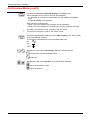
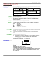
Installation
Location
Insertion/Extraction
The SD Card compartment is located on the right-hand side of the
oscilloscope near the communications interface connector.
- Insert the SD Card, in the card compartment, printed surface facing up.
- Push to the click Æ the card is in position.
- To remove the card, press slightly on the card and support it while
removing.
Operation
Recording
a file
• The filename is limited to a maximum of 20 characters + extension.
If this rule is not observed, the message: 'Filename too long’ is displayed.
• If the name already exists or is incompatible, an error message
‘Impossible! File already exists' will be displayed.
• By moving the pointer
onto the names of the files, you will see their
characteristics displayed (date and time saved and size).
SCOPIX
II - 23
Micro SD Memory Card
Micro SD Memory Card (cont’d)
Special folder
A specific folder on the SD Card, called "metrix", is used for recording files
by the oscilloscope.
From within the oscilloscope, the user can only act in this folder:
• File creation,
• File saving,
• File deletion.
If, at the moment of file saving, the "metrix" folder does not exist, it is
automatically created.
"Hot Plugging"
It is possible to insert or remove an SD Card from its compartment, even
when the oscilloscope is running. Never remove a card while a file is being
written on it. Doing so can cause the file save operation to fail, and even
damage the memory card.
If a window displaying the memory was open during card insertion/removal,
it is recommended to close it, then to open it again to update the display.
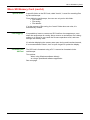
Formatting the
SD Card
The SD Card is formatted using a PC. It cannot be formatted via the
oscilloscope.
Two options:
- either using Windows software directly
- or using a specialised software application.
See next page.
II - 24
SCOPIX
Micro SD Memory Card
Micro SD Memory Card (cont’d)
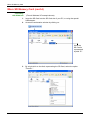
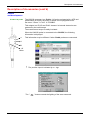
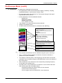
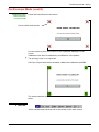
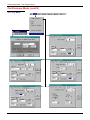
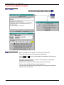
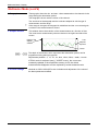
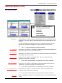
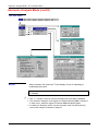
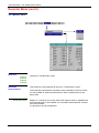
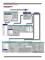
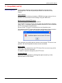
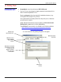
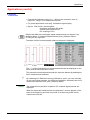
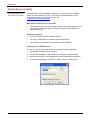
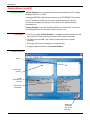
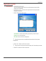
Formatting
with Windows
(French Windows XP example shown)
1.
Insert the SD Card into the SD Card slot of your PC, or using the special
USB adapter.
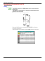
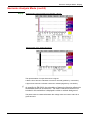
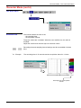
2.
Access the workstation window by clicking on:
Here, the
SD Card is
represented
by disk "E:"
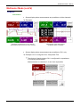
3.
SCOPIX
By a right click on the disk, representing the SD Card, select the option
"Format..."
II - 25
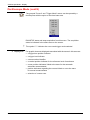
Micro SD Memory Card
Micro SD Memory Card (cont’d)
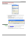
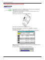
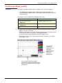
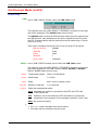
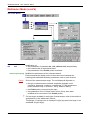
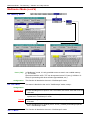
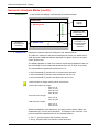
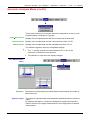
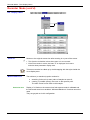
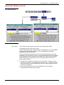
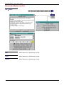
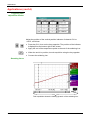
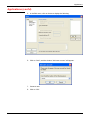
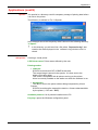
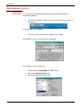
The "Format disk…" window appears:
4. In the "File System" block, select option FAT (not FAT32, which is not
compatible with the oscilloscope).
Click on: "Start".
5. A message appears, warning that the formatting will delete all data
memorised on the SD Card.
If you really wish to continue, click on "OK". Formatting will begin.
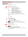
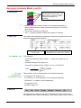
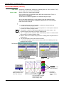
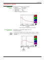
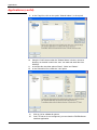
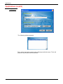
Formatting using
specialised
It is possible to download a free software called "SDFormatter" on this
software website: www.sdcard.org.
This software is specifically designed to format SD Cards.
Its use is very simple.
FAT16 format, compatible with the oscilloscope, is selected by default.
II - 26
SCOPIX
Micro SD Memory Card
SCOPIX
II - 27
Description of Accessories
Description of Accessories
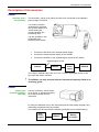
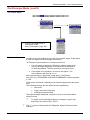
HX0061
Powering from a
vehicle battery
This accessory comes as an option and has to be connected to the standard
power supply of SCOPIX.
It is used by itinerant
technicians to recharge
the SCOPIX battery in a
vehicle during the
journey between two
measuring sites.
It is also possible to use
(and supply) the
SCOPIX in the vehicle.
1. Connect the SCOPIX to the external power supply.
2. Connect the external power supply to the HX0061.
3. Connect the HX0061 to the cigarette lighter socket of the vehicle.
Cigarette lighter socket
Vehicle
HX0061
Ext.
Power
supply
SCOPIX
The HX0061 module comes with a 12 VDC / 24 VDC cigar lighter socket of the
type normally used in vehicles.
*
The HX0061 can only be used with the instruments explicitly listed in its
operating guide.
HX0063
Charging the
instrument's battery
externally
Use this accessory, which comes
as an option, to charge the battery
when disconnected from the
instrument.
By using two batteries (one in the instrument and the other being charged), long
measuring campaigns are then possible.
The HX0063 can be used with the HX0061 (powering from a vehicle battery).
Ext.
Power
supply
III - 28
HX0063
Battery
in charge
SCOPIX
Description of Accessories
Description of Accessories (cont’d)
Concept
The portable oscilloscopes in this range use Probix intelligent probes and
adapters, offering users active safety.
When connected to an oscilloscope input, a safety message in English
concerning the probe or adapter used indicates:
• its maximum input voltage according to the category
• its maximum voltage in relation to the earth, according to the category
• its maximum voltage between channels, according to the category
• its type
• its basic specifications
• the use of suitable safety leads.
*
For user and instrument safety, this information must be respected.
Some probes are equipped with buttons whose assignment can be
programmed.
The colour of the signal measured with a particular accessory is
parameterised in the "Green" Æ "chX" Æ "Probix" menu. An
interchangeable elastic band or plastic collar can be used to match the
probe colour to the curve colour.
The scaling and the units are managed automatically by the Probix system, thus
allowing fast measurements and without risk of error.
The oscilloscope provides the power supply for the probes and adapters.
Recommendations for use: see p. 47.
SCOPIX
III - 29
Description of Accessories
Description of Accessories (cont’d)
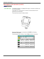
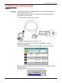
HX0030
and development
Probix 1/10 probe
The HX0030 accessory is a Probix 1/10 probe equipped with a LED and
pushbuttons (A and B), the action of which can be programmed via
the menu: "Green" Æ "chX" Æ "PROBIX".
This adapter is a PLUG and PLAY element. Its internal electronics are
powered by the oscilloscope.
The measurement output is totally insulated.
When the HX0030 probe is connected to the SCOPIX, the following
information is displayed.
Ño Ò
This information may be different if other Probix probes are connected.
A
B
HF
Offset
*
The positive input is indicated by a + sign.
The "ÑoÒ" button controls the lighting of the area measured.
III - 30
SCOPIX
Description of Accessories
Description of Accessories (cont’d)
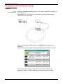
HX0031
Probix BNC adapter
The HX0031 accessory is a Probix BNC adapter, connected via a BNC lead
to a measuring signal.
This adapter is a “PLUG and PLAY” element. Its internal electronics are
powered by the oscilloscope.
The measurement output is totally insulated.
When the HX0031 probe is connected to the SCOPIX, the following
information is displayed.
This information may be different if other Probix probes are connected.
SCOPIX
III - 31
Description of Accessories
Description of Accessories (cont’d)
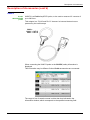
HX0032
Probix BNC 50Ω
adapter
The HX0032 accessory is a Probix adapter with a 50 Ω load, connected via
a BNC lead to a measuring signal.
This adapter is a “PLUG and PLAY” element. Its internal electronics are
powered by the oscilloscope.
To distinguish between this adapter and the HX0031, the measuring signal
unit via an HX0032 adapter is "VΩ"; this unit can be modified via the menu:
"Green" Æ "chX" Æ "Vertical scale".
*
The maximum input voltage to the HX0032 is 10 Vrms.
When the HX0032 probe is connected to the SCOPIX, the following
information is displayed.
This information may be different if other Probix probes are connected.
III - 32
SCOPIX
Description of Accessories
Description of Accessories (cont’d)
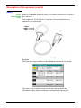
HX0033
Probix banana
adapter
∅ 4 mm:
The HX0033 accessory is a Probix adapter used to connect leads with
banana plugs.
This adapter is a “PLUG and PLAY” element. Its internal electronics are
powered by the oscilloscope.
The measurement output is totally insulated.
When the HX0033 probe is connected to the SCOPIX, the following
information is displayed.
This information may be different if other Probix probes are connected.
SCOPIX
III - 33
Description of Accessories
Description of Accessories (cont’d)
HX0034
Probix current
clamp adapter
The HX0034 accessory is a Probix current clamp using a Hall-effect cell to
measure DC or AC currents up to 80 A peak, without any intervention on
the electrical installation (cutting off the current to be measured).
A voltage output transducer, this clamp is a "PLUG and PLAY" element. Its
internal electronics are powered by the oscilloscope.
The action generated by the pushbuttons (A and B) can be programmed via
the menu "Green" Æ "chX" Æ "Probix". Use the third pushbutton (Offset) to
adjust the residual offset (see below).
The measurement output is totally insulated.
Utilisation
1. Connect the clamp to the oscilloscope: it is recognized by the
instrument and the measurement unit is displayed in A/div. on
screen.
2. Adjust the offset by pressing the "Offset" button.
The offset can only be adjusted when no current is present.
However, the presence of a DC current is permitted. In this case,
the offset will be obtained in relation to this initial current.
A
B
Offset
3. Use the trigger to open the jaws of the clip and then insert the
conductor, respecting the current direction.
4. Close the clamp. Make sure that it is properly closed and centred on
the conductor for optimum measurement accuracy.
When the HX0034 probe is connected to the SCOPIX, the following
information is displayed.
This information may be different if other Probix probes are connected.
III - 34
SCOPIX
Description of Accessories
Description of Accessories (cont’d)
HX0035
and development
Probix
K Thermocouple
adapter
The HX0035 accessory is a Probix adapter used to linearise temperature
measurements from a K-type thermocouple.
This adapter is a “PLUG and PLAY” element. Its internal electronics are
powered by the oscilloscope.
Thermocouple and earth are electrically insulated.
The signal unit measured via an HX0035 is "°C".
When the HX0035 probe is connected to the SCOPIX, the following
information is displayed.
This information may be different if other Probix probes are connected.
Measurements are available 30 sec. after connection of the HX0035, after a
calibration phase.
During this phase, the following message is displayed:
SCOPIX
III - 35
Description of Accessories
Description of Accessories (cont’d)
HX0036
Probix PT100
adapter
The HX0036 accessory is a Probix adapter used to linearise temperature
measurements from a PT100.
This adapter is a “PLUG and PLAY” element. Its internal electronics are
powered by the oscilloscope.
PT 100 and earth are electrically insulated.
The signal unit measured via an HX0036 is "°C".
When the HX0036 probe is connected to the SCOPIX, the following
information is displayed.
This information may be different if other Probix probes are connected.
Measurements are available 30 sec. after connection of the HX0036, after a
calibration phase.
During this phase, the following message is displayed:
III - 36
SCOPIX
Description of Accessories
Description of Accessories (cont’d)
HX0072
Probix
AmpFLEX probe
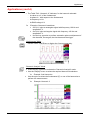
HX0072 is a Probix AmpFLEX probe, to be used to measure AC currents of
up to 3000 ARMS.
This adapter is a “PLUG and PLAY” element. Its internal electronics are
powered by the oscilloscope.
3000 A~
1000 V CAT III
600 V CAT IV
When connecting the HX0072 probe to the SCOPIX, safety information is
displayed.
This information may be different if other Probix accessories are connected.
The range of use for weak currents is wider than that indicated in the
information window, which corresponds to the specified measuring field.
SCOPIX
III - 37
Description of Accessories
Description of Accessories (cont’d)
HX0073
Probix
MiniAmpFLEX
probe
HX0073 is a Probix AmpFLEX probe, to be used to measure AC currents of
up to 300 ARMS.
This adapter is a “PLUG and PLAY” element. Its internal electronics are
powered by the oscilloscope.
300 A~
1000 V CAT III
600 V CAT IV
When connecting the HX0073 probe to the SCOPIX, safety information is
displayed.
This information may be different if other Probix accessories are connected.
The range of use for weak currents is wider than that indicated in the
information window, which corresponds to the specified measuring field.
III - 38
SCOPIX
Description of Accessories
Description of Accessories (cont’d)
HX0073
Probix
MiniAmpFLEX
probe
HX0073 is a Probix AmpFLEX probe, to be used to measure AC currents of
up to 300 ARMS.
This adapter is a “PLUG and PLAY” element. Its internal electronics are
powered by the oscilloscope.
300 A~
1000 V CAT III
600 V CAT IV
When connecting the HX0073 probe to the SCOPIX, safety information is
displayed.
This information may be different if other Probix accessories are connected.
The range of use for weak currents is wider than that indicated in the
information window, which corresponds to the specified measuring field.
SCOPIX
III - 39
Description of Accessories
Description of Accessories (cont’d)
HX0093
Probix
low-pass filter
HX0093 is a Probix low-pass filter of third order (cutoff = 300 Hz).
This adapter is a “PLUG and PLAY” element. Its internal electronics are
powered by the oscilloscope.
The measurement output is totally insulated.
When connecting the HX0093 to the SCOPIX, safety information is displayed.
This information may be different if other Probix accessories are connected.
III - 40
SCOPIX
Description of Accessories
Description of Accessories (cont’d)
HX0094
Probix
4-20 mA adapter
HX0094 is a Probix 4-20 mA adapter.
This adapter is a “PLUG and PLAY” element. Its internal electronics are
powered by the oscilloscope.
The measurement output is totally insulated.
When connecting the HX0094 to the SCOPIX, safety information is displayed.
This information may be different if other Probix accessories are connected.
SCOPIX
III - 41
Description of Accessories
Description of Accessories (cont’d)
HX0095
Probix
4-20 mA adapter
HX0095 is a Probix 4-20 mA adapter.
This adapter is a “PLUG and PLAY” element. Its internal electronics are
powered by the oscilloscope.
The measurement output is totally insulated.
When connecting the HX0095 to the SCOPIX, safety information is displayed.
This information may be different if other Probix accessories are connected.
III - 42
SCOPIX
Description of Accessories
Description of Accessories (cont’d)
HX0096
Probix
1000V adapter
HX0096 is a Probix 100mV adapter.
This adapter is a “PLUG and PLAY” element. Its internal electronics are
powered by the oscilloscope.
When connecting the HX0096 to the SCOPIX, safety information is displayed.
This information may be different if other Probix accessories are connected.
SCOPIX
III - 43
Description of Accessories
Description of Accessories (cont’d)
III - 44
SCOPIX
Description of Accessories
Description of Accesories (cont’d)
SCOPIX
III - 45
Description of Accessories
Description of Accesories (cont’d)
III - 46
SCOPIX
Description of Accessories
Description of Accessories (cont’d)
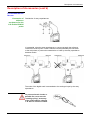
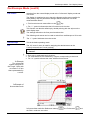
Connection
Disconnection
A window indicating the safety conditions is displayed when you connect or
disconnect a Probix to/from one of the instrument channels:
General
characteristics
of the last
adapter
connected
Input:
Maximum voltage
of the signal
measured by the
Probix adapter
Between channels:
Maximum admissible voltage
between channels (this voltage
depends on the combination of
Probix adapters connected)
Floating input:
Maximum voltage
permitted on each
Probix terminal in
relation to the
earth
SCOPIX
III - 47
Description of Accessories
Description of Accessories (cont’d)
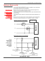
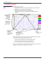
Recommandations
for use
Connection of
reference
conductors for the
1/10 Probix HX0030
probe
Distribution of stray capacitances:
It is essential, given the stray capacitances, to connect properly the reference
conductors for each probe. These conductors should preferably be connected
to the cold points, to prevent the transmission of noise by the stray capacitance
between modes.
The noise of the digital earth is transmitted to the analogue input by the stray
capacitance.
To prevent electric shocks or
possible fire, never use the
“earthing spring” accessory
of the 1/10 probe for voltages
> 30 Vrms in relation to earth.
III - 48
SCOPIX
Oscilloscope Mode - The Keys
Oscilloscope Mode
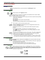
The Keys
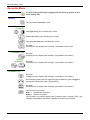
By pressing this key, you can select the "oscilloscope" mode.
5 "UTILITY" keys or
key pad
Direct access to LCD light adjustment.
When this key is pressed, the display mode switches from normal to "full
screen" display (and vice versa).
The screen is organized in such a way as to leave an optimum trace plotting
surface area, removal of:
the menu bar,
the parameters of the traces of the time base,
the bargraph.
Only the permanent settings and the measurements will remain.
The controls on the front panel remain active.
Triggers a hardcopy in accordance with the configuration chosen in the
"Util" and "Hardcopy" menus.
A second press before the end of the process will interrupt the current
printout.
If printing is impossible, a "Printing error" message will be sent.
The "
" symbol is displayed in front of the settings display zone when
printing is in progress.
The first press will freeze the traces on the screen. They will be displayed in
a lighter colour as a reference to be compared with another acquisition.
A second press will erase them: they will then be lost.
• Traces will be saved only through the "Memory
Trace
Save" menu.
• The reference memories will be accompanied by their reference number.
1 "AUTOSET" key
Automatic optimum adjustment by Autoset on the channels where the signal
is applied.
This affects parameters: coupling, vertical sensitivity, time base, trigger type
and slope and trace positionning.
The lowest frequency signal is used as the trigger source.
If no trace is detected on the inputs, the autoset will be aborted.
Selective
"AUTOSET"
+
SCOPIX
When pressed at the same time as a CHx key (CH1 to CH4), this defines
the corresponding channel as the trigger source. It initiates an autoset which
will take this selection into account. Channel CHx then becomes active for
adjustment using the keys:
IV - 49
Oscilloscope Mode - The Keys
Oscilloscope Mode (cont’d)
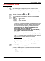
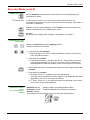
4 "Trigger" keys
Sets the trigger level to the average value of the signal (50%) without
modifying the trigger coupling.
When pressed in combination with a CHx key, this activates the same the
same function, after first selecting the corresponding channel as the trigger
source.
selects the trigger slope (up
or down
The slope is indicated in the status area.
) by successive presses.
Successive presses can be used select one of the following acquisition
modes:
Single shot
(Mono) = SINGLE
Triggered
Trig
Automatic
(Auto) = REFRESH
• "SINGLE" mode:
In Single Shote mode, a single acquisition is armed by pressing the RUN
HOLD key. After receiving a trigger, the waveform is displayed and the
instruments returns to HOLD mode. For any further acquisition, the
acquisition must be rearmed by pressing the RUN HOLD key.
If the time base is less than 100 ms/div
SINGLE mode can be
accessed via the "Mono (< 100 ms/div)" option.
If not, Single mode can be accessed via the “Roll Mono (> 50ms/div.)”
option and ROLL mode is automatically activated.
• "TRIGGERED" mode:
The screen's content is only refreshed when there is a trigger event linked
to the signals present on the oscilloscope's inputs (CH1, CH2, CH3, CH4).
If there is no trigger event linked to the signals present on the inputs (or if
there is no signal on the inputs), the trace is not refreshed.
• "AUTOMATIC" mode:
The screen's content is refreshed even if the trigger level is not detected
on the signals present on the inputs.
When there is a trigger event, screen refreshing is managed as in the
"Triggered" mode.
• allows acquisition to be started and stopped in "TRIGGERED" and
"AUTOMATIC" modes.
• rearms the trigger circuit in "SINGLE" mode.
Acquisition is initiated according to the conditions defined by the acquisition
mode (SGLE REFR key).
The acquisition status is indicated in the status area:
RUN
= started
STOP
= stopped
PRETRIG = acquisition
IV - 50
SCOPIX
Oscilloscope Mode - The Keys
Oscilloscope Mode (cont'd)
3 "MEASURE" keys
Displays or hides a window for the 19 automatic measurements on the
reference trace.
When pressed in combination with a CHx key, it displays the
measurements concerning the corresponding channel.
By means of successive presses, this selects one of the displayed traces as
the reference trace for the automatic and manual measurements.
It appears in the "Measure" menu
Reference.
Activates or deactivates the cursor display for manual measurements.
The cursors can be moved directly on the touch -sensitive pad using the
stylus.
• The "dt" measurements (time difference between the two cursors)
and "dv" measurements (voltage difference between the 2 cursors) are
indicated in the status area.
• The absolute value of the cursor selected is indicated in the "Current
Settings” area.
3 "HORIZONTAL" keys
or key pads
Adjustment of the time base coefficient (T/DIV).
After a Zoom, the "Z-Pos." setting modifies the position of the screen in
the acquisition memory.
Activates or deactivates the "Zoom" function.
By default, the zoom is performed around the samples located in the
middle of the screen.
A zone can be zoomed by tracing a rectangle around the area to be
enlarged using the stylus on the touch-sensitive pad. The sensitivity, time
base and horizontal and vertical alignment values are recalculated
automatically.
SCOPIX
IV - 51
Oscilloscope Mode - The Keys
Oscilloscope Mode (cont'd)
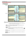
Definition of terms
used
5 "VERTICAL" keys
or key pads
OX 7204
Validated channel:
Displayed channel:
Selected channel:
Display enabled, trace displayed after RUN
Channel validated, trace present on the screen
The parameters of this channel can be set with the keys:
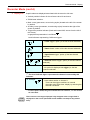
Step 1
Before pressing one of the
following keys :
Step 2
Press
The channel concerned is
not displayed.
Step 1
Before pressing one of the
following keys :
Step 3
After pressing one of the
preceding keys:
The channel is displayed and
selected.
The vertical sensitivity and
vertical position are assigned
to the channel selected.
The channel is selected.
The channel concerned is
displayed, but not selected.
The channel concerned is
displayed and selected.
OX 7202
and
The channel is cancelled by
double-pressing.
Step 2
Press
The channel concerned is
not displayed.
The channel concerned is
displayed, but not selected.
The channel concerned is
displayed and selected.
Step 3
After pressing one of the
preceding keys:
The channel is displayed and
selected.
On CH1 and CH4, the vertical
sensitivity and the vertical
position are assigned to the
channel selected.
The channel is selected.
The channel is cancelled by
double-pressing.
A long press on one of the keys CHx causes a vertical autoset:
• This modifies the sensitivity and vertical positioning of the channel in
question.
• It optimizes the display on the screen by activating and selecting the
channel.
The channel is displayed and selected.
IV - 52
SCOPIX
Oscilloscope Mode - The Keys
Oscilloscope Mode (cont'd)
Activates or deactivates horizontal splitting of the display zone.
When activated, the "Full Trace" function is indicated by:
- the presence of a continuous horizontal line in the middle of the display
area
- horizontal splitting of the graticule.
After activation of the function:
- traces 1 and 3 are assigned to the upper part of the display,
- traces 2 and 4 are assigned to the lower part in order to prevent overlays.
The traces can then be moved vertically in the two zones.
This function can also be used in "full screen" mode.
Successive presses allow selection of the input coupling (AC, DC or GND)
for the last channel selected.
The coupling is indicated in the channel parameters area:
AC :
DC :
GND :
Adjustment of the vertical sensitivity of the last channel selected:
increases the vertical sensitivity, while
reduces it.
Adjustment of the vertical position of the last channel selected:
moves it downwards, while
moves it upwards.
SCOPIX
IV - 53
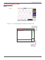
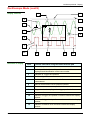
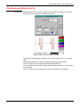
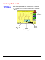
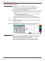
Oscilloscope Mode - Display
Oscilloscope Mode (cont'd)
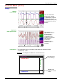
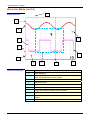
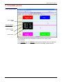
Display
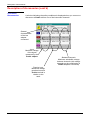
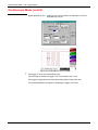
Display
Cursor2
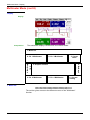
Composition
The oscilloscope display is divided into 4 functional zones.
Direct access to
main settings
4. Menu bar
2. Control area
3. Display area
1. Status area
Display and
adjustment of
current value
IV - 54
SCOPIX
Oscilloscope Mode - Display
Oscilloscope Mode (cont'd)
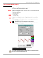
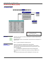
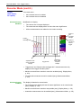
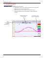
1. Status area
Three types of general information appear in this area:
• The bargraph representing the screen position, the trigger and the
cursors in the acquisition memory.
• The instrument permanent settings.
• The measurements, when the cursors are present on the screen.
Bargraph
Cursor measurements
or last setting
(displayed for 2 seconds)
Representation and
movement of the screen in
acquisition memory
(1)dt=110,0µs, div=100.0µV
Movement towards left of
screen in acquisition
memory
1
Trig
Permanent settings
1 Pretrig
2
T
Position and movement
of time trigger
Position and movement of
manual cursors
Movement towards right of
screen in acquisition
memory
Each element in the bargraph can be moved with the stylus.
Permanent settings
This zone refers to the trigger status (mode, edge, source, current status).
Example: AUTO
1 STOP
When the stylus is placed on this information, the "Trigger Parameters"
menu can be opened by pressing twice.
Cursor
measurements
This zone refers either to:
• the horizontal (dt) and vertical (dv) differences between 2 cursors in the
case of manual measurements
Example: (1) dt = 110.0 µs, div = 100.0 µV
• phase measurement in the case of manual phase measurement (Ph).
Example: (1) Ph = 200.0°
• the automatic measurements selected using the "Automatic
Measurements" or "Phase measurement" menus
Example: (2) F = 1.0000 kHz, Vpp = 7,500 V
SCOPIX
IV - 55
Oscilloscope Mode - Display
Oscilloscope Mode (cont'd)
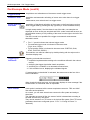
The parameters displayed in this area are:
• The parameters of each channel and trace: display, sensitivity, coupling,
bandwidth limitation, vertical scale, function, Zoom.
2. Control area
• The time base value, the presence of a Zoom and a change in the signal
representation domain (FFT).
• Active adjustment of the last selected element:
trigger level
trigger time position
channel offset value
X & Y position of cursor
• Time display, if no measurement has been selected.
• Display of the battery status
• A mains socket if the instrument is connected to the Wall Plug.
Display of the trace parameters (in the
colour of the trace):
validity, coupling, bandwidth limitation,
sensitivity
Display of ZOOM mode
or
Display of the math function parameters
(in the colour of the trace):
validity, value of one division
Display of ZOOM mode
or
Display of memories (M): validity
Value of time base coefficient (s/div) in
oscilloscope mode or of the frequency
(Hz/div) in FFT mode
Light
25.0 %
IV - 56
Change of signal representation domain
(FFT selection)
Indication and adjustment of last setting
selected
•
The channels and functions can be validated using the stylus or the keys.
•
The " " symbol indicates whether a channel or function is selected, or
whether FFT mode is selected.
•
The settings of the time base (or the frequency) and the value of the active
parameter can be modified using the UP/DOWN button next to the display of
the current value.
•
After modification of the time base, the corresponding sampling frequency
is indicated in the settings area.
•
A double press on the parameters or a channel or on the value of the time
base directly opens the associated menus:
- Sensitivity/Coupling and Vertical Scale, for the channels
- Vertical scale for the functions
- Source, trigger mode and RUN/STOP, for the time base.
SCOPIX
Oscilloscope Mode - Display
Oscilloscope Mode (cont'd)
The grouped "Source" and "Trigger Mode" menus can be opened by a
double press with the stylus on the time base area.
RUN/STOP starts and stops acquisition from this menu. The acquisition
status is indicated in the status area on the screen.
The symbol " " indicates the source and trigger mode selected.
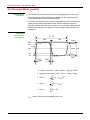
3. Display area
The graphic elements displayed associated with the traces in this area are:
• a trigger time position indicator
• a trigger level indicator
• a trace number identifier
• a vertical position indicator for the reference level of each trace
• cursor position indicators linked to the trace for the automatic
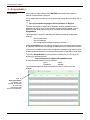
automatic measurements
• position indicators regarding the cursors linked or not to the trace
for manual measurements
• selection of a zoom zone
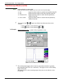
SCOPIX
IV - 57
Oscilloscope Mode - Display
Oscilloscope Mode (cont'd)
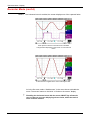
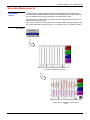
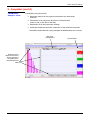
Display elements
3
6
>
1
10
2
ϕ
8
5
6
2
1
v
12
Definition of display
v
4
Refs.
7
9
11
Elements selectable using the touch-sensitive pad
Trace displayed
1
Trace
displayed
Vertical position indicator of the reference level of the trace
2
displayed and identification of the trace number
IV - 58
3
Indication of Trigger time position
4
Division of graticule
5
Position indicator of the cursors for the first automatic
measurement
6
Manual measurement cursor position indicator
7
Phase measurement cursor position indicator
8
Trigger level and coupling on the trigger position indicator
9
Selection of a zoom zone
10
Indicator of trigger time position overshoot outside the display
window
11
Indicator of trigger level position overshoot outside the display
window.
12
Indicator of channel level overshoot outside the display
window.
SCOPIX
Oscilloscope Mode - Display
Oscilloscope Mode (cont'd)
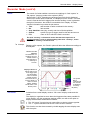
Menu accessible
from display area
By double-tapping with the stylus in the
display area, the menu concerning the
display can be opened directly.
The "Full Screen" and "Zoom Out"
options are directly accessible (see §.
Display Menu). The same applies to the
selection of the automatic and manual
measurement reference signal (see §.
Measure Menu).
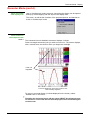
It is possible to use the stylus to zoom in the display area by pulling a
rectangle.
After zooming in on part of the screen, the sensitivities of the traces and
the time base are recalculated.
• The symbol "Z" appears in the signal and time base parameters
display.
• The zoomed section is represented in the bargraph.
• The "Zoom Out" menu (see §. Display Menu) or the Zoom
key can be used to return to the original display.
• The value of the horizontal zoom is adjusted to assign a calibrated
value to the horizontal scale (zoom factor: x 5 max.)
• If the vertical selection of the zoom is greater than 6 divisions, no
vertical zoom is performed (zoom factor: x 16 max.).
All the symbols present in the display area:
- trigger indicators,
- trace position indicator,
- manual cursor position indicator,
- etc.
can be moved using the stylus.
The new modified symbol value is indicated in the current settings
display area.
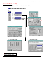
Calibration of the
touch-screen
To optimize selection of the different elements present in the display area
using the stylus, calibration of the touch-sensitive screen may prove
necessary.
Select the "Touch Screen Calibration" option proposed in the display area
menu or in the Util menu.
By double tapping on the curves zone, you can also access touch-screen
calibration.
SCOPIX
IV - 59
Oscilloscope Mode - Display
Oscilloscope Mode (cont'd)
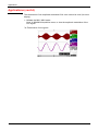
Calibration of the
touch-sensitive
screen (cont'd)
Follow the instructions on the screen.
Corner of the touch screen
Use the stylus to point at the centre of the 4 patterns displayed on the
screen.
Validation of the input is indicated by modification of the pattern.
The pointing order is not important.
Once the 4 inputs have been recorded, validate the calibration with OK.
The touch-sensitive screen is calibrated and the display returns to normal
mode.
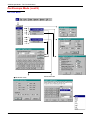
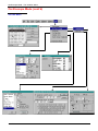
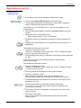
4. Menu bar
All the oscilloscope functions can be accessed via the main menus.
IV - 60
SCOPIX
Oscilloscope Mode - The "Vertical" Menu
Oscilloscope Mode (cont'd)
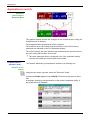
The "Vert" Menu
≠ Advanced mode
SCOPIX
Advanced mode
IV - 61
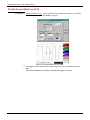
Oscilloscope Mode - The "Vertical" Menu
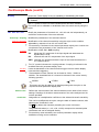
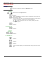
Oscilloscope Mode (cont'd)
Opens the "Trace display" menu for validating or devalidating the traces.
Display
Validation of the selections by "OK". Exit from the menu without modification
by "Cancel".
The " " symbol in front of a trace indicates that it has been validated.
The traces can be validated or devalidated from the control area by using the
stylus.
ch1 ch2 ch3 ch4
Sensitivity / Coupling
Channel Sensitivity
Coupling
Modify the parameters of channels ch1, ch2, ch3 and ch4 independently, as
well as the vertical scale of the trace selected.
Modifies the parameters of the selected channel.
Modification of the channel's sensitivity using the stylus on the scrollbar,
adjustable by sequence: from 2.5 mV to 200 V/div.
The sensitivity is indicated in the channel parameter display area. It takes into
consideration the parameters of the "Vertical scale" menu.
Modification of AC - DC - GND coupling
AC:
blocks the DC component of the input signal and attenuates the
signals below 10 Hz
DC:
transmits AC and DC components of the input signal
GND: internally, the instrument links the input of the channel selected to a
0 V reference level.
The " " symbol indicates the coupling selected. Coupling is indicated in the
modified channel's parameter display area.
bw limit
Limits the bandwidth of the channel and its trigger circuit to reduce display
noise and false triggering.
The bandwidth of each channel can be limited to 5 kHz, 1.5 MHz or
20 MHz. The bandwidth limit of a channel is indicated in the control area by
following symbols :
20 MHz
1.5 MHz
5 kHz
This menu can also be called up by double-pointing with the stylus on the
required channel parameter display area.
Vertical scale
Coefficient
Defines the vertical scale of the channel selected on the basis of the current
settings. Readings of the direct measurements of the value analyzed and its
unit are provided.
Assignment of a multiplication coefficient to the selected channel's sensitivity.
This can be modified with the stylus, using the table of usable numbers, after
selecting the "Coefficient" zone.
The
key deletes the character preceding the cursor in this area.
The predefined values (x1, x10, x100, x1000) correspond to standard probe
coefficients and can be assigned directly.
The sensitivity value indicated in the channel parameter display will be
modified according to this coefficient.
IV - 62
SCOPIX
Oscilloscope Mode - The "Vertical" Menu
Oscilloscope Mode (cont'd)
Measurement unit
Modification of the selected channel's vertical scale unit.
The modification is performed by means of the stylus, using the table of
usable characters after selecting the “measure unit” zone.
The
key deletes the character preceding the cursor in this area.
The vertical scale unit will be indicated in the modified channel's parameter
display.
Init
Reinitializes the multiplication coefficient to 1.00 and returns to the V
measurement unit.
Validation of the selections by "OK". Exit from the menu without modification
by "Cancel".
This menu can also be called up by double-pressing with the stylus on the
required channel's parameter display area (CH1, CH2, CH3 or CH4).
Probix
ÑoÒbutton
Buttons A and B
When selected, this opens the "Probe Configuration" menu.
When a Probix HX0030 (or HX0034) probe is connected to one of the
oscilloscope's inputs, this menu becomes active.
The can be used to switch the LED on or off.
can be assigned to different settings (see table below).
Button B
Button A
ÑoÒ
A
B
Sensitivity
Higher sensitivity
Lower sensitivity
Vertical/horizontal
alignment
Alignment on higher
division
Alignment on lower
division
Time base
Higher time base
Lower time base
Auto Meas. Ref. Meas.
AUTO MEAS. CHx
REF MEAS.
Autoset CHx / Auto 50 %
Auto CHx
AUTO 50 % CHx
•
•
•
Colour
RUN HOLD
Trig. edge / Run-Hold
See the chapter on "The Keys" for further details on the function provided.
The modified parameters are updated in the control area.
The “ " symbol indicates the parameters elected and assigned to the
probe.
modifies the colour that you want to assign to the trace.
•
•
The “ " symbol indicates the colour selected.
These parameters will be memorized in the probe, even after
disconnection of the oscilloscope.
When using Probix adapters, the choice of the colour remains possible.
SCOPIX
IV - 63
Oscilloscope Mode - The "Vertical" Menu
Oscilloscope Mode (cont'd)
math1 math2
math3 math4
Function definition
For each trace, definition of a mathematical function and the vertical scale.
If "Advanced" mode is not activated, simple functions (Inversion, Addition,
Subtraction, Multiplication and Division of curves) can be selected and
linked to the curves 1 or 2.
In "Advanced" mode, mathematical functions can be defined literally.
The mathematical function can be defined on 2 lines.
• The mathematical function can be defined on 2 lines.
• mathx cannot be used in the definition of a function.
The
Functions
key deletes the character preceding the cursor in the window.
8 predefined mathematical functions can be linked to the traces:
divh(
("horizontal division")
divv(
("vertical division")
step(
("step") using "t" (∗)
sin(
("sine")
cos(
("cosine")
exp(
("exponential")
log(
("logarithmic")
sqrt(
("square root")
(∗) t = abscissa of the sample in the acquisition memory.
divh(1) is equivalent to 250 samples (counts) = 1 horizontal division
(or 5000 samples if the EXTENDED ACQUISITION MEMORY
option is installed).
Validation of the selections by "OK". Exit from the menu without modification by
"Cancel".
If …
then …
... the dynamic calculation of the
vertical scale is impossible
... a message indicates that the
measuring unit on this function will
be vertical division (div).
... the dynamic calculation of the vertical
scale is possible
... it takes into account of the
sensitivities of the channel sources.
Particular cases :
Value of the measuring unit
CHx + CHy
Sensitivity and measuring unit used on CHx
CHx - CHy
Sensitivity and measuring unit used on CHx
In each cases, the measuring unit can be re-defined and a coefficient can be
applied to the measurement results (refer to §. Vertical scale).
IV - 64
SCOPIX
Oscilloscope Mode - The "Vertical" Menu
Oscilloscope Mode (cont'd)
Examples
Use of predefined
mathematical
functions
• Predefined divv() function used on its own: math3 = divv(3).
The trace is equal to 3 vertical divisions.
• Predefined step() function associated with a trace:
- math2 = ch1*step(t-divh(4))
The result of math2 is 0 vertical divisions as long as t is less than
four horizontal divisions (t-divh(4) < 0).
The result of math2 is equal to ch1 when t becomes greater than
four horizontal divisions (t-divh(4) > 0).
- math2 = ch1*step(divh(4)-t)
The result of math2 is equal to ch1 as long as t is less than four
horizontal divisions (t-divh(4) > 0).
the result of math2 is at 0 vertical divisions when t becomes greater
than four horizontal divisions (t-divh(4) < 0).
SCOPIX
IV - 65
Oscilloscope Mode - The "Vertical" Menu
Oscilloscope Mode (cont'd)
Example 1
Addition of two
traces
Vhigh
Vpp(ch1) = Vpp(ch2) = 6 V
Sensitivity (ch1) = 1 V/div
Sensitivity (ch2) = 1 V/div
Traces ch1 and ch2 are optimised on 6 vertical divisions.
Vamp ch1 = 6 vertical divisions
Vamp ch2 = 6 vertical divisions
- math3 = ch1+ch2
Vertical scale math3 = 2.00 div
Vpp math3 = 12.00 div
Vhigh math3 = 6.00 div
There is a high and low overshoot, so division by 2 is necessary to
optimize display of the result.
- math3 = (ch1+ch2) / 2
Vertical scale math3 = 2.00 div
Vpp math3 = 12.00 div
Vhigh math3 = 6.00 div
Division by two adjusts the addition to the dynamics of the screen.
Vamp math3 = 6 vertical divisions
The measuring unit and the sensitivity of ch1 are used during the
display of measurements.
You can then open the menu “Vertical Scale" of math3 (see §. Opening
from math3, math4) to assign a coefficient to the result and to modify
the measuring unit.
IV - 66
SCOPIX
Oscilloscope Mode - The "Vertical" Menu
Oscilloscope Mode (cont'd)
Example 2
Multiplication of two
traces
Sensitivity(ch1) = 5 V/div
Sensitivity(ch2) = 5 V/div
Vamp(ch1) = Vamp(ch2) = 10 V
Vamp ch1 = 2 vertical divisions
Vamp ch2 = 2 vertical divisions
- math3 = ch1*ch2
As for the addition of traces, there is a even more significant high and low
overshoot.
The overshoot is due to the increased dynamics of the numbers after a
multiplication ; to avoid this and standardize the result, use the divv ()
function.
Example: If Amplitude on CH1 = 2 divv and Amplitude on CH2 = 2 divv, the
following function is used to get an amplitude of 1 divv :
math3 = (ch1 * ch2) / divv (1)
The result of the multiplication is translated into divisions on the screen.
- If Vamp ch1 = 8 div and Vamp ch2 = 8 div, the result
must be divided by divv(4) to obtain Vamp math3 = 4 div.
- When mathematical functions associated with traces are used, the
dynamics of the result obtained must be verified.
Correction of the result of the operations by mathematical functions (divv(),
divh(), / …) is recommended to optimize the screen display.
SCOPIX
IV - 67
Oscilloscope Mode - The "Vertical" Menu
Oscilloscope Mode (cont'd)
You can then open the menu “Vertical Scale" of math3 (see §. Opening
from math3, math4) to assign a coefficient to the result and to modify the
measuring unit.
In our example:
• Then select math3 as the reference for the automatic and manual
measurements (see §. "MEASURE" Menu).
• Then display the table of 19 measurements made on the math3 trace
math3 (see §. "MEASURE" Menu).
The measurements displayed are the exact result of the multiplication of
the two traces ch1 and ch2 in the unit (V).
Sensitivity(math3) = 25 VV
Vpp (math3) = 25 VV
IV - 68
SCOPIX
Oscilloscope Mode - The "Vertical" Menu
Oscilloscope Mode (cont'd)
Example 3
- math3 = divv(3)*sin (2*pi*t/500) (∗)
Association
of predefined
functions
The trace obtained is a sine-curve produced using the predefined
function "sin()".
The amplitude is 6 divisions.
The period equal to 500 samples (∗∗) (2 horizontal divisions) depends
on the time base.
• Same trace produced with the predefined divh() function:
math3 = divv(3)*sin(2*pi*t/divh(2))
In this example, divh(2) is equivalent to 500 samples (∗∗).
The period divh(2), equal to 500 samples (∗∗) (2 horizontal divisions),
depends on the time base.
• Production of a sine wave by the predefined cos() function:
math3 = divv(3)*cos(2*pi*t/divh(2))
The trace obtained with the predefined cos() function is offset by 90°.
(∗) math3 = div(3) sin (2pi*t / 10 000) if EXTENDED ACQUISITION MEMORY
option is installed.
(∗∗) 10 000 samples with EXTENDED ACQUISITION MEMORY option
SCOPIX
IV - 69
Oscilloscope Mode - The "Vertical" Menu
Oscilloscope Mode (cont'd)
Production of an
attenuated sine wave
using predefined
functions
math1 = sin (pi*t/divh(1))*exp(-t/divh(6))*divv(4)
"sin (pi*t/divh(1))" can be used to modify the number of periods.
"exp (-t/divh(6))" can be used to modify the level of attenuation.
IV - 70
SCOPIX
Oscilloscope Mode - The "Vertical" Menu
Oscilloscope Mode (cont'd)
Function definition
(cont'd)
Files
Contains the list of the functions (.FCT) saved by the user, along with two
predefined files.
By selecting the name of the function with the stylus (function name in blue),
you can transfer the definition of the function into the 2 lines provided for that
purpose.
The scroll bar can be used to scroll through the list of memorized functions.
The function can be modified with the table of usable characters, associating
the ch1 and ch2 traces.
This menu also contains two predefined functions.
C1MULC2.FCT and SQUARE.FCT
C1MULC2 .FCT
Product of 2 traces with scaling:
math3 = ch1*ch2/divv(4) = C1MULC2.FCT
The factor divv(4) is used to optimize the display as long as the source signals
have sufficient dynamics (> 6 divisions) and no overshooting.
SQUARE .FCT Definition of a square signal using the first 4 harmonics of a Fourier series
development.
math3 = SQUARE.FCT
math3 = (sin(pi*t/divh(2)) + sin(3*pi*t/divh(2))/3 + sin(5*pi*t/divh(2))/5
+ sin(7*pi*t/divh(2))/7)*divv(4)
SCOPIX
IV - 71
Oscilloscope Mode - The "Vertical" Menu
Oscilloscope Mode (cont'd)
Save
Reset
Saves the definition of the function using the “File Copy “ menu (see §.
Memory Menu). The file is assigned the suffix .FCT and appears in the list of
saved files.
Completely resets the function definition.
After assigning a function to the ch1 (math1), ch2 (math2), ch3 (math3) or ch4
(math4) channels, "mathx" appears in the corresponding channel's parameter
display area.
Vertical scale
Definition of the vertical scale for the selected trace
Calling this menu from math1 to math4 is identical to calling ch1 to ch4 as
long as the functions have not been defined.
Opening of the menu
from:
math1 math2
math3 math4
Coefficient
Modifies the value of a division (div) in the selected trace.
This can be modified with the stylus, using the table of usable numbers, after
selecting the "Coefficient" zone.
The
key deletes the character preceding the cursor in this area.
The predefined values (x1, x10, x100, x1000) correspond to standard probe
coefficients and can be assigned directly.
The value of a division will be entered into the display of the modified trace
parameters.
Measurement unit
Modification of the unit of the vertical scale (div) for the selected trace.
This can be modified with the stylus, using the table of usable numbers, after
selecting the measurement unit zone.
The
key deletes the character preceding the cursor in this area.
The "±" key can be used to switch between upper case and lower-case
characters.
The vertical scale unit will be entered into the modified trace's parameter
display (3 characters max).
Init
Reinitialization of the multiplication coefficient to 1.000 and return to the V
measurement unit.
Validation of the selections by "OK". Exit from the menu without modification
by "Cancel".
The "Vertical scale" menu can also be called up by double pressing with the
stylus in the parameter display of the required trace (math1 to math4).
IV - 72
SCOPIX
Oscilloscope Mode - The "Trigger" Menu
Oscilloscope Mode (cont'd)
The "Trig" Menu
SCOPIX
IV - 73
Oscilloscope Mode - The "Trigger" Menu
Oscilloscope Mode (cont'd)
Definition
This range of portable oscilloscopes is equipped with "advanced triggers".
•
The "Delay" and "Count" trigger modes require parameterization of a
second "auxiliary" trigger source. The auxiliary source may be the same as
the main source.
The trigger choice is validated by exiting from the menu.
If …
then …
… the user exits from the
"Main" tab,
… "Main" triggering is used.
… the user exits from the
"Pulse" tab,
… "Pulse" triggering is used.
etc.
etc.
• There is only one Holdoff, although it can be programmed from the "Main",
"Delay", "Count" or “TV” tabs.
When you use "Delay" or "Count", the Holdoff applies to the auxiliary source,
i.e. the source of the count pulses or delay trigger pulses.
In the other cases, Holdoff applies to the main trigger source.
• Each trigger source has its own specific attributes: Coupling, Level, Edge,
Noise Reject, Filter.
You can also
choose the
trigger channel
by doubletapping with the
stylus in the
time base
display area.
You can also choose the trigger
parameters by double-tapping with the
stylus in the display area of the trigger
parameters.
IV - 74
SCOPIX
Oscilloscope Mode - The "Trigger" Menu
Oscilloscope Mode (cont'd)
Selection of the "Trigger Parameters".
Parameters
Main
Source
Coupling
Trigger on edge
selects a channel as a trigger source.
Selection of the filter for the main trigger source:
AC
AC coupling (10 Hz to 200 MHz):
blocks the DC component of the signal
DC
DC coupling (0 to 200 MHz):
allows the entire signal through
LF Reject
Rejection of source signal frequencies < 10 kHz:
facilitates observation of signals with a DC
component or an unwanted low frequency
HF Reject
Rejection of source signal frequencies > 10 kHz:
facilitates observation of signals with high-frequency
noise.
The symbol used to indicate the curve trigger level on the curve also indicates the
coupling:
DC
AC
LF Reject
HF Reject
Edge
Selection of the trigger gradient:
+ ascending trigger edge
-
descending trigger edge
The selected trigger edge is indicated the status area.
Level
2.04V Adjustment of the trigger level with the stylus on the scroll bar.
The trigger level is entered into the current value display area after modification.
Fine adjustment is possible.
Noise reject
No: hysteresis ≈ 0.5 div.
Yes: introduces a hysteresis of ≈ 1.5 div.
Holdoff
108µs
allows:
• disabling of the trigger for a predefined period
• stabilization of the trigger on pulse trains.
Double-tapping in this field displays a virtual numeric keypad which can be used
to directly input the value.
SCOPIX
IV - 75
Oscilloscope Mode - The "Trigger" Menu
Oscilloscope Mode (cont'd)
Example
Signal injected on CH1: a train of three 6 VDC pulses at a frequency of 20 kHz
with a 500 mVDC component, separated by 500 µs.
The trigger is regulated with channel 1 as a source, level at 2.04 V, on a rising
edge.
The Holdoff stabilizes the signal by inhibiting the trigger during 108 µs.
The DC coupling of the trigger lets the whole signal through.
In this example, the signal is not being disturbed and the option of noise reject is
not necessary.
The DC coupling of ch1 reveals the continuous component of the signal.
IV - 76
SCOPIX
Oscilloscope Mode - The "Trigger" Menu
Oscilloscope Mode (cont'd)
Pulse
Trigger selection on pulse width.
In all cases the effective triggering occurs on the end of pulse edge.
t > T1
triggers if pulse duration is greater than specified value T1
t < T2
triggers if pulse duration is less than specified value T1
t > T1 and t < T2
triggers if pulse duration is within interval specified by
values T1 and T2
t < T1 or t > T2
triggers if pulse duration is outside interval specified by
values T1 and T2
The choice of the
analysis:
Example
or
edge in the "Main" tab defines the limits of the
• edge
defines a pulse between
and
• edge
defines a pulse between
and
Signal injected on CH1: 1 pulse of 50 µs (repetitive or not)
The oscilloscope triggers when it sees a pulse whose duration is greater
than specified value (25.0 μs + tolerance). The trigger occurs on the trailing
edge of the pulse.
The trigger occurs on the ascending edge of the pulse, but is effective on the
trailing edge.
SCOPIX
IV - 77
Oscilloscope Mode - The "Trigger" Menu
Oscilloscope Mode (cont'd)
Delay
Selection of edge trigger with delay
The delay is triggered by the auxiliary source.
Effective triggering occurs after the end of the delay on the next event from the
main source.
35.2µs
Trigger delay
Adjustment with the stylus using the setting scroll bar to choose the
required delay value.
Double-tapping in this field displays a virtual numeric keypad which can be used
to directly input the value.
108µs
Holdoff
Adjustment with the stylus using the setting scroll bar, allows
disabling of the trigger for a predefined period and, among other
things, stabilization of the trigger on pulse trains.
Double-tapping in this field displays a virtual numeric keypad which can be used
to directly input the value.
Qualifier
Trigger
Coupling
selects the settings on the qualifier source
selects the settings on the trigger source
selects the filter for the auxiliary trigger source:
AC
AC coupling (10 Hz to 200 MHz):
blocks the DC component of the signal
DC
DC coupling (0 to 200 MHz):
allows the entire signal through
LF Reject
Rejection of source signal frequencies < 10 kHz:
facilitates observation of signals with a DC
component or an unwanted low frequency
HF Reject
Rejection of source signal frequencies > 10 kHz:
facilitates observation of signals with high-frequency noise
Level
2.04V
Edge
selects the edge for the auxiliary trigger source:
Noise reject
Adjustment of the trigger level with the stylus on the scroll bar.
+
rising trigger edge
-
falling trigger edge
No: hysteresis ≈ 0.5 div.
Yes: introduces a hysteresis of ≈ 1.5 div.
IV - 78
SCOPIX
Oscilloscope Mode - The "Trigger" Menu
Oscilloscope Mode (cont'd)
Example
Signal injected on CH1: a train of three 6 VDC pulses at a frequency of 20 kHz
separated by 500 µs.
The trigger is active after the end of the delay (35.2 µs) on the first ascending
edge.
The Holdoff stabilizes the signal by disabling the trigger for 108 µs.
SCOPIX
IV - 79
Oscilloscope Mode - The "Trigger" Menu
Oscilloscope Mode (cont'd)
Count
Selects the edge trigger with counting of events.
The count is triggered by the auxiliary source. The main source serves as a
clock for the count.
Effective triggering occurs after the end of the count on the next event from the
main source.
3
Trigger delay
Adjustment with the stylus using the setting scroll bar to choose the
number of events required.
Double-tapping in this field displays a virtual numeric keypad which can be
used to directly input the value.
Holdoff
232µs Adjustment with the stylus using the setting scroll bar, disabling of
the trigger for a predefined period and, among other things,
stabilization of the trigger on pulse trains.
Double-tapping in this field displays a virtual numeric keypad which can be used
to directly input the value.
Qualifier
Trigger
Coupling
Edge
selects the settings on the qualifier source
selects the settings on the trigger source
Selection of the filter for the auxiliary trigger source:
AC
AC coupling (10 Hz to 200 MHz):
blocks the DC component of the signal
DC
DC coupling (0 to 200 MHz):
allows the entire signal through
LF Reject
Reject of source signal frequencies < 10 kHz
facilitates observation of signals with a DC component
HF Reject
Rejection of source signal frequencies > 10 kHz:
facilitates observation of signals with high-frequency noise
Selection of the trigger slope :
+
trigger on rising edge
-
trigger on falling edge
The selected trigger slope is indicated the status area.
Level
Noise reject
IV - 80
1.09V
Adjustment of the trigger level with the stylus on the scroll bar.
•
No: hysteresis ≈ 0.5 div.
•
Yes: introduces a hysteresis of ≈ 1.5 div.
SCOPIX
Oscilloscope Mode - The "Trigger" Menu
Oscilloscope Mode (cont'd)
Example
Signal injected on CH1: a train of five 6 VDC pulses at a frequency of 20 kHz
separated by 500 µs.
The trigger is set on the descending edge.
The first edge activates the trigger. It is not included in the count.
The trigger is triggered on the third descending edge of the pulse train.
The Holdoff stabilizes the signal by disabling the trigger for 232 µs.
SCOPIX
IV - 81
Oscilloscope Mode - The "Trigger" Menu
Oscilloscope Mode (cont'd)
TV
Standard
Polarity
Holdoff
Line
Trigger on a TV signal
See Chapter VI - Applications: §. Video signal display.
This menu is only applicable to the CH1 input.
Trigger on a specific line number. The trigger starts on the front edge of the line
synchronization signal.
• 625 lines (SECAM) or
• 525 lines (PAL)
+
-
Direct video
Reverse video
Adjusted by scrolling with the stylus. Triggering impossible for a pre-defined
time.
Double-tapping in this field displays a virtual numeric keypad which can be
used to directly input the value.
25
Adjustment of the no. with the stylus using the scroll bar.
Double-tapping in this field displays a virtual numeric keypad which can be
used to directly input the value.
The " " and “ ” symbols indicate the selected parameters.
Validation of the selections by "OK".
The "Trigger Parameters" menu can also be called up by double-pointing with
the stylus in the trigger settings display area.
IV - 82
SCOPIX
Oscilloscope Mode - The "Trigger" Menu
Oscilloscope Mode (cont'd)
Triggered mode
Acquisitions and refreshment of the screen at each trigger event.
Automatic mode
Acquisition and automatic refreshing of screen even when there is no trigger
event.
Visible traces, even when there is no trigger event.
Single mode and
Roll mode
Acquisition of signal and refreshing of the screen on the first trigger occurring
after a trigger reset by pressing the key opposite (or via the time base menu).
In single-sweep mode, if the time base is over 50 ms/div, new samples are
displayed as soon as they are acquired and ROLL mode is activated as soon as
the acquisition memory is full (scrolling of the trace from the right to the left of the
screen).
The ROLL mode is not possible if the trigger on automatic measurement
threshold is active.
• The " " symbol indicates the selected trigger mode.
• The selected trigger mode is indicated in the status area
(Trig'd, Auto, Single).
• The acquisition status is indicated in the status area: PRETRIG, RUN,
STOP, POSTRIG, READY, …
This selection can also be called up by double-pointing with the stylus on the
time base display area.
Triggering on
thresholds
Triggering on thresholds consists of:
1. acquisition implemented according to the conditions defined in the various
menus,
2. analysing the trigger signal after classic acquisition,
3. searching for a condition on an automatic measurement,
4. if this condition is met, displaying the validated signals.
If "measurement on thresholds" is activated, the status zone at the foot of the
screen indicates it.
When threshold values are input, the instrument displays an error message if the
measurement of a threshold value is impossible.
Save / Restart
SCOPIX
If this option is activated, all the traces acquired are saved to .TRC and .MAC
files after each acquisition.
As a result, you can save several rare events to the file system and analyse
them later.
The channels are saved in files, the name of which is determined according to
the date and time they are saved.
They can be saved on an FTP server or in the local file system if the FTP server
parameters have been configured (menu: "UTIL"
"Config I/O Ports"
"Network")
IV - 83
Oscilloscope Mode - The "Horizontal" Menu
Oscilloscope Mode (cont'd)
The "Horiz" Menu
(∗)
(∗)
(∗) Function accessible only in
"Advanced" mode.
See §. Description, page 105.
Repetitive Signal
Increase in the time definition of a trace for a periodic signal. If this option
is valid, the signal can be averaged (see below).
Example: measurement on a microprocessor bus.
•
For time bases of less than 100 µs/div. (without mode zoom
active), the signal displayed is reconstituted on the basis of
several acquisitions. The time resolution can reach 20 µs.
•
If the signal is not repetitive, do not use this option. The
time resolution will then be ± 1 ns.
Menu present only in "Advanced" mode (see §. "Util" Menu).
Also refer to §. "EXTENDED ACQUISITION MEMORY" option operation
p. 188.
If this option is selected, rebuilding a full coherent signal may take some
time.
The following settings will also affect the time significantly:
• time base,
• trigger recurrence frequency
• averaging function activity.
The signal settings (amplitude, frequency, form) must remain stable
during running.
To speed up the rebuilding following a change in signal, stop
Run.
acquisition and restart: Stop
The " " symbol indicates that the "Repetitive Signal" option has been
selected.
IV - 84
SCOPIX
Oscilloscope Mode - The "Horizontal" Menu
Oscilloscope Mode (cont'd)
Min/Max
Acquisition
Use this mode to view the extreme values of the signal acquired between
2 acquisition memory samples.
This mode:
• detects wrong representation due to under-sampling
• displays short-term events (Glitch, ≥ 2 ns).
Whatever time base is used and the corresponding sampling speed, shortterm events (Glitch, ≥ 2 ns) are displayed.
The "
Averaging
" symbol indicates that the "Min/Max Acquisition" mode is active.
Selection of a coefficient to calculate an average for the displayed samples:
No averaging
Average rate 2
Average rate 4
Average rate 16
Average rate 64
with:
i. e. this is a way of attenuating random noise observed in a signal.
For the averaging coefficient to be taken into account for representation of
the signal, the "Repetitive signal" option must be selected.
The calculation is performed using the following formula:
Pixel N = Sample*1/Average rate + Pixel N-1 (1-1/Average rate)
Sample
Value of new sample acquired at abscissa t
Pixel N
Ordinate of pixel with abscissa t on the screen, at moment N
Pixel N-1
Ordinate of pixel with abscissa t on screen, at moment N-1
The " " symbol indicates the averaging coefficient selected.
FFT
(Fast Fourier
Transform)
The Fast Fourier Transform (FFT) is used for calculating the discrete
representation of a signal in a frequency domain from its discrete
representation in the time domain.
FFT can be used in the following applications:
• measurement of the different harmonics and the distortion of a signal,
• analysis of a pulse response,
• search for noise source in logic circuits.
The FFT is calculated over 2500 points.
The Fast Fourier Transform is selected by the FFT icon in the control area.
When the trace is zoomed, the FFT applies to the zoomed part of the trace
(next to the time base adjustment).
Description
The Fast Fourier Transform is calculated using the equation:
1
X (k) =
*
N
N
−1
2
⎛ 2πnk ⎞
x(n) * exp⎜ − j
⎟ for k ∈ [0 (N – 1) ]
⎝
N ⎠
N
∑
n= −
2
with: x (n): a sample in the time domain
X (k): a sample in the frequency domain
N: resolution of the FFT
n: time index
k: frequency index
The displayed trace represents the amplitude in V or dB of the various
signal frequency components according to the scale selected (linear or log).
The DC component of the signal is removed by software.
SCOPIX
IV - 85
Oscilloscope Mode - The "Horizontal" Menu
Oscilloscope Mode (cont'd)
Square signal
FFT with a Hanning window and a log
scale
Horizontal unit
Vertical unit
FFT with a rectangular window and a
linear scale
This is indicated instead of the time base and is calculated according to the
scanning coefficient:
12.5
Unit (in Hz/div.) =
scanning coefficient
Two possibilities are offered by the sub-menus:
by selecting the FFT menu and then the linear scale
a) Linear scale:
unit
of the signal in its time representation (V/div.)
• in V/div. =
2
b) Logarithmic scale:
by selecting the FFT menu and then
log scale (logarithmic)
• in dB/div. =
by assigning 0 dB to a signal with an effective
amplitude of 1 in the time representation
The vertical position indicator of the representation is at -40 dB.
Graphic
representation
IV - 86
The FFT representation indicates symmetry in relation to the frequency
origin; only positive frequencies are displayed.
SCOPIX
Oscilloscope Mode - The "Horizontal" Menu
Oscilloscope Mode (cont'd)
The sub-menus select a type of window.
Rectangular
Hamming
Hanning
Blackman
Flat Top
Before calculating the FFT, the oscilloscope weights the signal to be
analyzed by means of a window acting as a band-pass filter. The choice of
window type is essential to distinguish between the various lines of a
signal and to make accurate measurements.
Time representation
of signal to be
analyzed
Weighting window
Weighted signal
Frequency
representation of
signal calculated by
FFT
SCOPIX
IV - 87
Oscilloscope Mode - The "Horizontal" Menu
Oscilloscope Mode (cont'd)
The finite duration of the study interval results in a convolution in the signal
frequency domain with a function sinx/x.
This convolution modifies the graphic representation of the FFT because
of the lateral lobes characteristic of the sinx/x function (unless the study
interval contains an whole number of periods).
Five types of window selections are available: the menus appear directly
on selection of the FFT menu.
Width of main
lobe at -3 db
(bin)
Max. amplitude of
secondary lobe (dB)
Rectangular window
0.88
- 13
Hanning window
1.30
- 31
Hamming window
1.44
- 43
Blackman window
1.64
- 58
Flat top
3.72
- 93
Type of window
Effects of under-sampling on frequency representation:
If the sampling frequency is not correctly adjusted (less than or twice the
maximum frequency of the signal to be measured), the high-frequency
components will be under-sampled and appear in the graphic
representation of the FFT by symmetry (aliasing).
• The "Autoset" function is active. This prevents the phenomenon above
and adapts the horizontal scale: the representation is more legible.
• The "Zoom" function is active.
The " " symbol in front of one of the options indicates the function
selected.
"EXTENDED
ACQUISITION
MEMORY"
option operation
IV - 88
If the "EXTENDED ACQUISITION MEMORY" option is installed
(see §. Menu " ? " "Options"):
• The acquisition memory is extended from 2,500 samples to 50,000
samples.
• On the time base range [1 ns, 5 ms], the signal image is obtained by the
aggregate of several acquisitions and reconstruction. Deactivate the
"HORIZ "
"Repetitive Signal" option if the signal observed is not
periodical, acquired and synchronous with the trigger.
• On the time base range [10 ms, 200 s], 50,000 samples are obtained in
one acquisition.
SCOPIX
Oscilloscope Mode - The "Display" Menu
Oscilloscope Mode (cont'd)
The "Display" Menu
(∗)
(∗) Function only accessible
in "Advanced" mode.
See §. Description, page 105.
Grid
Display / Removal of graticule
Display modes
There are two display modes available: vector and envelope.
Vector
Envelope
A vector is plotted between each sample.
The minimum and maximum observed on each horizontal position of the
screen are displayed. This mode is used, for example, to view a time or
amplitude variation or a modulation.
The “ ” symbol indicates the active display mode.
All samples
The entire acquisition (2,500 or 50,000 samples depending on the
instrument) is displayed on the screen and a vector traced between each
sample.
Use this mode to view all acquisition details. This function can be used for
a memory or curve already acquired.
Accumulate
Accumulation of the different acquisitions on the screen.
The most recent acquisition is displayed using a highlighted colour.
Zoom off
Returns to the original screen size after zooming in on part of the screen.
• This function is inactive unless the screen is in zoom mode.
• If the Zoom mode is active, the letter "Z" is displayed in the trace
and time-base parameter display area.
This menu can also be called up by double-pointing with the stylus inside
the trace display area.
SCOPIX
IV - 89
Oscilloscope Mode - The "Display" Menu
Oscilloscope Mode (cont'd)
Full screen
Switches from the normal display mode to the “full screen” display mode and
vice versa.
The display is organized so as to leave the biggest surface area possible for
trace plotting: only the permanent settings and the automatic or manual
measurements remain.
• This function has the same effect as the
key.
• The “ ” symbol indicates that the full screen mode is active.
This function can also be called up by double-pointing with the stylus on the
trace display area.
The settings defined on the front panel remain active.
The following sub-menus can be used to switch from oscilloscope to XY mode.
The “ ” symbol indicates the active mode.
Oscilloscope
This is the basic operating mode.
XY
The “XY source” menu is used for assigning the desired traces to the
X axis (horizontal) and Y axis (vertical).
Validation of the selections by "OK". Exit from the menu without modification
by "Cancel".
• Each axis is graduated into 8 divisions.
• The selected traces are identified by a figure corresponding to their axis.
• The “ ” symbol indicates the trace selected for each axis.
Example
Two sinusoidal
signals assigned to
the X and Y axis with
an offset of π/2 are
then represented by
a circle.
Example of
Accumulate mode
In Accumulate mode the Reference memory
the ROLL mode are not active.
IV - 90
, the Full screen
and
SCOPIX
Oscilloscope Mode - The "Measure" Menu
Oscilloscope Mode (cont'd)
The "Measure" Menu
(∗)
(∗) Function only accessible
in "Advanced" mode.
See §. Description, page 105.
Reference
Trace 1
Trace 2
Trace 3
Trace 4
Selection of the trace on which the automatic or manual measurements
will be performed.
Only the active traces can be selected. Inactive traces are displayed in a
lighter colour.
The " " symbol indicates the reference trace.
Automatic
measurements
Opens the "Automatic measurements" menu window.
The measurements are performed and refreshed on the selected
reference trace. All the measurements that can be performed on this
trace are displayed.
(- . - -) is displayed for measurements that cannot be performed.
The window can be validated and closed by pointing to OK with the
stylus.
The selected measurement(s) will be displayed in the status area.
SCOPIX
IV - 91
Oscilloscope Mode - The "Measure" Menu
Oscilloscope Mode (cont'd)
• It is possible to select two permanent measurements.
• The " " symbol indicates the measurement(s) that will be indicated
in the status area.
• Activation of the automatic measurements causes two markers (+) to
appear on the curve, if at least one period is visible on the screen.
• The display order corresponds to the chronological order of the
selection and the markers are assigned to the first measurement
selected.
Automatic measurements in the status area can be deleted by means of
this menu, by erasing the selected measurements (no " " symbol in the
automatic measurements table).
Reference memory
difference
Activation of the "Reference memory difference" option is a way of
calculating the deviations, for all the automatic measurements, between
the selected trace and the memorized reference trace (see §. Memory
Menu).
Example
Calculation performed and displayed on one of the 20 automatic
measurements:
Vpp (Ref. memory difference) = Vpp (Trace 1) – Vpp (Trace 1
Ref 1)
The calculation is performed in the same way for all the measurements.
• This option is only active if a reference trace is present.
It must correspond to the trace on which you wish to perform
automatic measurements
( Example: Trace 1 and Trace 1
Ref. 1).
• Condition: the reference trace must have the same characteristics as
the associated trace (sensitivity and time base)
20 automatic
measurements
IV - 92
Vmin
Vmax
Vpp
Vlow
Vhigh
Vamp
Vrms
Vrms_c
Vavg
Sum
Trise
Tfall
W+
WP
F
DC
N
Over+
Over-
minimum peak voltage
maximum peak voltage
peak-to-peak voltage
established low voltage
established high voltage
amplitude
rms voltage performed on measurement intervals
rms voltage performed on an integer number of cycles
average voltage
summon of instantaneous values of the signal
rise time
fall time
positive pulse width (at 50 % of Vamp)
negative pulse width (at 50 % of Vamp)
period
frequency
cyclic ratio
number of pulses
positive overshoot
negative overshoot
SCOPIX
Oscilloscope Mode - The "Measure" Menu
Oscilloscope Mode (cont'd)
Measurement
conditions
• The measurements are performed on the displayed part of the trace.
• Any change to the signal will lead to updating of the measurements.
They are refreshed in step with acquisition.
• To perform automatic measurements on specific portions of the signal,
frame the required measurement area with the manual cursors so
that the markers show the new location of the automatic measurement.
• Measurement precision is optimum if two complete signal periods are
displayed.
Automatic
measurement
presentation
TP = 1/F
W
W+
100%
90%
W
W-
Vmax
Vhigh
high
>5%T
Vavg
avg
50%
Vamp Vpp
10%
0%
low
Vlow
Vmin
Trise
Trise
t0
t1
t2
Tfall
>5%T
t3
t4
t6
t5
• Positive overshoot = [100 * (Vmax – Vhigh)] / Vamp
• Negative overshoot = [100 * (Vmin – Vlow)] / Vamp
• Vrms =
[
1
i= n
∑ (y − y
n
i
i= 0
• Vavg =
• Vsum =
1
n
i =n
∑ (y
i= 0
i=n
(y
∑
i= 0
i
i
GND
)2 ]1/2
− y GND )
× δt)
YGND = value of the point representing zero volt
SCOPIX
IV - 93
Oscilloscope Mode - The "Measure" Menu
Oscilloscope Mode (cont'd)
Phase measurement
Trace1 Phase
Trace2 Phase
Trace3 Phase
Trace4 Phase
Automatic measurement of a trace's phase compared with a reference trace
(See §. Reference Measurement).
This menu selects the trace on which phase measurements are to be
performed.
To deactivate phase measurement, deselect the selected phase measurement
using the same menu.
• The " " symbol indicates the trace selected for phase measurement.
• Activation of the phase measurement, if it is possible, will cause display
of 3 markers:
2 markers for the reference trace period
1 marker indicated as ϕ on the trace for which the phase
measurements will be performed.
These 3 markers are positioned automatically; they cannot be moved.
• The phase measurement (in °) of the trace selected compared with the
reference trace is indicated in the measurement display status area
Example: (1)Ph (2) = 180.0°
• If the measurement cannot be performed, " - . - -" is displayed.
Manual
measurements
(dt, dv)
Cursor measurements on the reference signal
The measurement cursors (1 and 2) are displayed as soon as the menu is
activated.
The two measurements made are:
dt (time difference between the two cursors),
dv (voltage difference between the two cursors).
The measurements performed and the displayed cursors are linked to the
selected reference trace (see §. Reference Measurement).
• The " " symbol indicates that the manual measurements (dt, dv) are active.
• the measurement cursors can be moved directly with the stylus.
They can also be moved with the stylus by selecting the 1 (cursor 1)
or 2 (cursor 2) in the bargraph.
• If the free cursor option is not active (see §. "Unattached Cursors"
Measurement), the cursors will remain linked to the reference trace during
movements. If the option is active, the cursors can be moved
anywhere on the screen.
• The dt and dv measurements in relation to the selected reference
are indicated in the measurement display status area.
Example: (1)dt = 500.0 µs, dv = 1.000 V
Manual phase
measurement
Phase measurements using 3 cursors:
- Use cursors 1 and 2 to indicate the period of the reference signal.
- Use the ϕ cursor to measure the phase.
• The " " symbol indicates that manual phase measurement is active.
• When this menu is active, the 3 cursors are present if at least one
signal is active.
• The cursor marked ϕ can be moved freely, even if the "Unattached
cursors" menu is not active.
• The phase measurement (in °) between the cursors is indicated in the
measurement display status area.
Example: (1)Ph = 120.0 °
IV - 94
SCOPIX
Oscilloscope Mode - The "Measure" Menu
Oscilloscope Mode (cont'd)
Unattached manual
cursors
Used for linking or not linking the manual measurement cursors (1 and 2)
to the reference trace.
When the "Unattached cursors" menu is selected, cursors 1 and 2 can
be moved freely over the whole screen.
• The " " symbol indicates that the "Unattached cursors" menu is active.
• To deactivate this menu, deselect it by pointing with the stylus.
In the case of "Automatic measurements" and manual measurement
activation:
If …
then …
… the manual cursors and the
automatic markers are
displayed together,
… the automatic measurements
are performed on the portion of the
trace defined between the manual
cursors.
… the portion defined between
the manual cursors is too
small [in this case, the fixed
markers (+) will not be
displayed],
… the automatic measurements
selected are impossible, so "-.--" is
indicated in the measurement
display area.
Deselect the automatic measurements to validate the manual
measurements (dt, dv).
SCOPIX
IV - 95
Oscilloscope Mode - The "Memory" Menu
Oscilloscope Mode (cont'd)
The "Memory" Menu
Trace 1
Trace 2
Trace 3
Trace 4
Ref. 1
Ref. 2
Ref. 3
Ref. 4
Storage of the selected trace in its reference memory
( E.g.: Trace 1 in Ref. 1).
The 4 traces have their reference memory.
A reference memory is volatile, which means that it is lost when the
instrument is switched off.
• For optimum use, the reference trace must have the same
characteristics as the associated trace (sensitivity and time base).
• A trace can only be saved in its reference memory if it is present
on the screen
• The memorized traces are displayed in a light colour, accompanied by
their reference number.
• The " " symbol in the menu means that the corresponding trace has been
saved in the reference memory and that it is present on the screen.
• A reference trace cannot be moved.
• A reference memory can be deactivated by deselecting it in the menu.
IV - 96
SCOPIX
Oscilloscope Mode - The "Memory" Menu
Oscilloscope Mode (cont'd)
Trace
Saving (to the non-volatile memory) or recall of a trace or a reference
memory. The back-up can be saved in two formats: ".TRC" or ".TXT".
The "File copy" menu is adapted to the type of format selected.
Save .TRC
Save.TXT
Saving of the files for subsequent recall on the oscilloscope screen
The back-up files will take the suffix .TRC; they can be recalled in the
"Trace Recall" menu.
Saving of files for export to another application
The saved files have the suffix .TXT; they cannot be recalled by the "Trace
Recall" menu for screen display. However, they can be exported in a
standard format for use in other software (spreadsheet - e.g. Microsoft
EXCEL) using the menu "Util Files Export".
The selection made opens a "File Copy" menu.
∗ Then in the "Source" drop-down menu, select the trace or the
reference memory to be recorded.
∗ All the channels can be saved in one operation:
A .TRC file is created for each channel displayed
A .MAC file is created: this file contains the commands needed to
restore all the channels saved.
The trace or reference memory to be saved will appear in grey. The stylus
is used for selection.
• Only traces and reference memories present on the screen are
indicated in the "Source" list (selectable).
• Use the scrollbar on the right of the list to view all the elements.
∗ A default backup file name is proposed above the keyboard. A file is
generated from the date and current time. It can be modified using the
virtual keyboard with the stylus.
The
key deletes the character preceding the cursor in this area.
∗ Once the name has been written, the
key records it by entering it into
the destination menu and closes the menu. The backup file takes the
extension .TRC (internal format) or .TXT (text format), depending on the
previous selection.
Saving of the file is triggered with this key.
You can exit from this menu without saving by tapping with the stylus on
the icon in the top right-hand corner of the window.
• By moving the pointer
onto the names of the files, you will see their
characteristics displayed (date and time saved and size).
• If the name already exists or is incompatible, an error message
‘Impossible! File already exists' will be displayed.
• The filename is limited to a maximum of 20 characters + extension.
If this rule is not observed, the message: 'Filename too long’ is displayed.
SCOPIX
IV - 97
Oscilloscope Mode - The "Memory" Menu
Oscilloscope Mode (cont'd)
Recall .TRC
When selected, this opens a "File Copy" menu.
In the "Source" list, the .TRC files previously saved (via the menu "Trace
.TRC") are displayed.
Select the file to be called up from the list displayed.
Save
∗ Choose the destination from the "Destination" list.
∗ The destination trace selected is called up in the input zone.
∗ This key triggers call-up of the trace.
The menu can be exited without recalling by tapping the icon in the top righthand corner with the stylus.
• If you wish to recall in one action all the traces memorized jointly, open
corresponding ".MAC" file via menu "UTIL"
"Fichier" (File).
• If the destination trace selected is already present on the screen, it will be
overwritten by the trace called up.
• When a trace is recalled, Mx appears in the destination trace parameters.
• The virtual keyboard cannot be used in this menu.
Configuration
Saving or recall of an instrument configuration.
Save
When selected, this opens the "File copy" menu.
∗ The "Configuration" object is automatically selected in the "Source" list.
∗ A back-up file name is proposed above the Qwerty keyboard.
The
key deletes the character preceding the cursor in this area.
∗ A default save filename is proposed above the keyboard, generated from the
date and current time. It can be modified via the virtual keyboard using the
stylus.
The key deletes the character preceding the cursor in this area.
You can exit from this menu without saving by tapping with the stylus on the icon
in the top right-hand corner of the window.
• The filename is limited to a maximum of 20 characters + extension. If this rule
is not observed, the message: 'Filename too long’ is displayed.
• If the name already exists or is incompatible, an error message will appear
• By moving the pointer
onto the names of the files, you will see their
characteristics displayed (date and time saved and size).
Recall
When selected, this opens the "File Copy" menu.
In the "Source" list, the .CFG files saved (via the menu "Configuration
Save")
are displayed.
A particular file that is always present called "Default Config" contains the
instrument's default configuration.
Select the file to be called up from the "Source" list.
This key triggers callup of the configuration.
The virtual keyboard cannot be used in this menu.
IV - 98
SCOPIX
Oscilloscope Mode - The "Utilities" Menu
Oscilloscope Mode (cont’d)
The"Util" Menu
SCOPIX
IV - 99
Oscilloscope Mode - The "Utilities" Menu
Oscilloscope Mode (cont'd)
Selection of the "File Management" menu. It contains the files which have been:
• saved in previous sessions
• created since the last instrument startup.
• The storage capacity of the file system is 2 Mbytes.
These files will be saved in the FLASH memory when the instrument is
switched off with the button opposite: they will then be available for the
next session.
Files
By moving the pointer
onto the names of the files, you will see their
characteristics displayed (date and time saved and size).
The selected file appears in grey.
Use the scrollbar to the right of the list to scroll through the entire file system.
The erasing or copying can be long if the number of files concerned is
important.
File type
File name extension:
.CFG:
Configuration
.TRC:
Trace in OSCILLOSCOPE mode
.MAC:
SCPI commands (e.g.: to restore several traces)
.REC:
Traces in RECORDER mode
.TXT:
Text format file
.FCT:
Function in OSCILLOSCOPE and RECORDER mode
.PRN, .PCL, .EPS, .BMP, GIF: Print file
.∗ :
All files
Internal file on
the FTP server
Open
Erase
Erase ∗.∗
Export
Choose the file system to be viewed.
The internal file system is used by default when the window is opened.
File system selection can be accessed on the FTP server if the FTP server
parameters have been configured in the menu:
"Network" in 'advanced' mode.
"UTIL"
"CONFIG PORT D’E/S"
Opens the selected file, the resulting action depends on the file extension:
.CFG: Configuration restoration
.TRC: Restoration of a trace in OSCILLOSCOPE mode
.MAC: Execution of the SCPI commands contained in the file
.REC: Restoration of traces in RECORDER mode
.FCT:
Restoration of a function
.BMP: Display of the file using the "IMAGE/VIEWER"
.GIF:
Display of the file using the "IMAGE/VIEWER"
The other types cannot be opened on the instrument.
deletes the selected file.
deletes all the files, the extension of which is selected in the 'File type'.
Writing of the file selected from the list to an interface.
RS232, Centronics Network (FTP), Network (LPD), Internal file, SD CARD
You can exit from this menu by pointing with the stylus on the icon in the top
right-hand corner of the window.
IV - 100
SCOPIX
Oscilloscope Mode - The "Utilities" Menu
Oscilloscope Mode (cont'd)
I/O port config
USB In the "USB / RS232" window, check the USB Cable button.
This interface uses the (USB / RS232 / ETHERNET) connector on the right
side of the equipment. The HX0084 cable must be used.
The HX0084 cable converts the RS232 format output from the instrument to
the USB protocol. After installation of the driver supplied on the CD on the
host PC, communications with the instrument can be made using a "Virtual
Com Port" (VCP).
Take care to configure the Virtual Com Port on the host PC as follows:
Bits per second
460800
Data Bits
8 bits
Parity
None
Stop Bits
1
Flow control
Hardware
RS232 In the “USB / RS232” window, do not check the USB Cable button.
This interface uses the (USB / RS232 / ETHERNET) connector on the right
side of the equipment. The USB / RS 232 adapter (HX0084) or HX0042
RS232 / SUBD9 cable must be used.
Speed
Transmission speed:
300 to 115,200 Bauds.
Format
Word length:
7 or 8 bits.
Parity:
even, odd or no parity (none).
Stop bits
Number of stop bits:
1 or 2 stop bits
Protocol
Serial link management mode:
Parity
Hard Hardware: the protocol is provided by the RTS and CTS lines
of the RS232 link.
Soft
Software: use of the XON and XOFF characters to synchronize
transmission and reception of the messages (reduced “3-wire” link)
None No protocol checking
• The « » symbol indicates the selected option.
• The option can be modified using the stylus.
SCOPIX
IV - 101
Oscilloscope Mode - The "Utilities" Menu
Oscilloscope Mode (cont’d)
Network
provided by a
DHCP server
Configuration of the ETHERNET parameters
If this box is checked, the instrument makes a request to the network
DHCP server to automatically obtain:
• an IP address
• a subnet mask
• the gateway address
• possibly a network printer IP address
If the DHCP request fails, the device selects a free address in the address
area between 169.254.1.0 and 169.254.254.255.
When powering up, if you activated this protocol during a previous
session, a confirmation is requested before sending the DHCP
request via ETHERNET.
If the instrument is no longer connected to the network, answer “no”
to the question, otherwise it will wait several minutes for an answer
from the DHCP server, before becoming functional.
Physical address
Oscilloscope address on the ETHERNET network.
This address cannot be modified (it is specific to the instrument)
Example: 00-01-02-03-04-63
IP address
Oscilloscope IP address on the ETHERNET network.
This address can be input automatically or manually with the keyboard,
after selecting the zone to be modified.
The
key can be used to delete the value preceding the cursor in the
zone to be modified.
An IP address can be assigned automatically by a DHCP server, if the
server is accessible, by ticking the box “provided by a DHCP server”.
Example: 132.147.200.74
After modification, the IP address is displayed for 30’ at the bottom right of
the screen.
Printer (or Ipd server):
IP address
IP address of the printer or a PC where the printer is connected. In this
case, use the “Virtual Printers” software (refer to p. 203).
This address must be input manually with the keyboard, after selecting the
zone to be modified.
The
key can be used to delete the value preceding the cursor in the
zone to be modified.
Example: 132.147.240.1
IV - 102
SCOPIX
Oscilloscope Mode - The "Utilities" Menu
Oscilloscope Mode (cont'd)
Name
Name of the printer as it appears in the printing server (or PC).
If the printer is connected directly to the network, do not enter anything
here.
This key can only be accessed in Advanced mode.
Use this function to manually configure:
•
The subnet mask (SUBNET MASK)
•
The IP address of a gateway (GATEWAY)
If you press this key twice you will access:
•
The IP address of an FTP server
•
The user name and password to access the FTP server.
Validation of the selections by "OK". Exit from the menu without
modification by "Cancel".
SCOPIX
IV - 103
Oscilloscope Mode - The "Utilities" Menu
Oscilloscope Mode (cont'd)
The print format, the type of printer and the communication port are chosen from
this menu.
The print format should be selected from the list using the stylus. Use the
scrollbar to the right of the list to view all the printer languages available.
Hardcopy
Option
Port
Choice of colour or black/white printing.
Selection of the interface used for print data transfer:
USB or RS232 :
USB link interface or serial (acc. to selection in
USB/RS232 window)
Centronics :
parallel interface via HX0041option
Network (LPD) :
network printer or an LPD client
File (internal, FTP) :
internal file or on an FTP server
• If the RS232C interface is selected, the parameters (speed, format, parity,
stop bit, protocol) must be configured in the "Config I/O Ports" menu. Check
that the configuration matches the configuration of the peripheral device
connected to the instrument.
• If the "Network" option is selected, the parameters must be configured in the
“Config I/O Ports
Network" menu).
• The "File" option is a way of recording the hardcopy in a file.
".bmp" and ".gif" image formats can be used directly in the Windows
Windows applications (word processing, presentations, etc.) As soon as the
print request is launched, the "File copy" menu is opened and you should
"Save").
input the name of the file generated (see "Trace" menu
A hard copy of the screen can be printed by pressing this key. The copy is
printed using the parameters defined in the "Hardcopy" menu.
Configuration
Date/time
Langue
(Language)
Screen saver
Standby
Updating of the date (day, month, year) and the time (hour, minute, second).
You can select the required parameter by using the stylus and the scrollbars
located on either side of the parameters to be adjusted.
The clock starts when the menu is closed.
Selection of the language in which the menus are written.
Options available: French, English, German, Italian, Spanish, etc.
Sets the screen to standby after a defined period of time to minimize the
consumption of the equipment and screen ageing.
4 options are available: 15mins, 30mins, 1hr, no standby mode.
The screen can be reactivated by pressing any key on the front panel.
Shutdown of the instrument after a predefined period, in order to limit its energy
consumption.
In this case, the equipment configuration is saved before the shutdown.
4 options are available: 30mins, 1hr, 4hrs, none.
The equipment is reactivated using the key shown opposite or using a key on
the front panel, which will not be taken into account.
• The “ ” symbol indicates the selected option.
• The option can be modified using the stylus.
IV - 104
SCOPIX
Oscilloscope Mode - The "Utilities" Menu
Oscilloscope Mode (cont'd)
Display of data concerning the operation of the instrument since it was first
used.
System info
Autotest
This list displays the result of the self-test activated when the instrument is
switched on.
For verification of the instrument, see §. Maintenance p. 7.
Touch screen
calibration
The touch screen needs to be calibrated if the position of the mouse pointer
is offset from the stylus impact point on the touch screen or if access to x
different objects on the screen is difficult.
This calibration process is described on p. 59, 60.
"Advanced" mode
The "Advanced" mode gives access to certain additional functions. By
default the "Advanced" mode is not activated in order to simplify the use of
the equipment.
Accessed from
the menu
Selection in
advanced
mode
State in non
advanced mode
"Vert"
Complex
mathematical
functions
applicable to the
4 traces
Simple
mathematical
functions
applicable only
to traces 2 and 3
Repetitive signal
"Horiz"
Choice between
repetitive and
non repetitive
mode
Non repetitive
mode
Average
"Horiz"
No averaging.,
x2, x4, x16, x64
No averaging
"Display"
Choice between
Oscilloscope
(YT) and XY
Oscilloscope
(YT)
Free manual
cursors
"Measure"
Manual cursors
whether related
or not to the
reference trace
Cursors 1 and 2
related to the
reference trace
Access to FTP
server
“Memory”
Option that
can be selected
Option that cannot
be selected
(grayed)
Save / Recall
“Trigger”
Option that
can be selected
Option that cannot
be selected
Functions available in
"Advanced" mode only
Function
math1, math2,
math3, math4
XY
(default
configuration)
In "Advanced" mode, the instrument starts in the configuration where it
stopped; otherwise it starts in its default configuration (always the same one).
SCOPIX
IV - 105
Oscilloscope Mode - The "Utilities" Menu
Oscilloscope Mode (cont'd)
"Image Viewer" of
.GIF and .BMP files
Use the "Image Viewer" to display .GIF and .BMP files from a screen grab
(only on SCOPIX III).
The " Image Viewer " can be accessed from the file manager by opening a .GIF
or .BMP file.
Close the
"Image Viewer"
Go to the next
.BMP or .GIF
file
IV - 106
Deletion
(after confirmation)
of the file displayed
Go to the
previous
.BMP or .GIF
file
SCOPIX
Oscilloscope Mode - The "Help" Menu
Oscilloscope Mode (cont'd)
The « ? » Menu
Help
When selected with the stylus, this opens the "Help" menu.
The online help concerns the instrument's keyboard.
Use the Å and Æ keys to scroll through the description of the keys on
the front panel.
Whenever a keyboard key is pressed, online help will be displayed
regarding the key pressed.
The functions associated with the keys will not be activated.
The key name is indicated above the explanation.
You can exit from this menu by pointing with the stylus in the top righthand corner of the window.
SCOPIX
IV - 107
Oscilloscope Mode - The "Help" Menu
Oscilloscope Mode (cont'd)
This submenu provides information:
About
-
On the name of the instrument, the software version and the version of
the hardware
-
the WEB site to visit to find new products in the range for METRIX
instruments.
-
the email address of the customer service that can answer your
questions on the instrument.
You can exit from this menu by choosing OK.
Installation of the various instrument options.
Options
An option is installed by entering a 24-character code and clicking on the OK
key.
This is a unique code for the option acquired and for your instrument (it
cannot be installed on another instrument)
When an option is acquired, you must specify the serial number and key of
the instrument in your order and CHAUVIN-ARNOUX will supply you with
this code.
The serial number and key are indicated in the "Options" window title bar.
# : 123456ABC-2997
The list of options installed is also displayed in this window.
Options available:
¾ MULTIMETER
¾ HARMONIC ANALYSER
¾ RECORDER
¾ EXTENDED ACQUISITION MEMORY
¾ POWER MEASUREMENTS
*
IV - 108
The installation of a new option is integrated after the instrument is
restarted.
SCOPIX
Multimeter Mode - The Keys
Multimeter Mode
The Keys
Press the key opposite to select the "Multimeter" mode.
4 "UTILITY"keys or
key pads
Direct access to LCD light adjustment.
No action.
Triggers a hardcopy in accordance with the configuration chosen in the "Util"
and "Hardcopy" menus.
A second press before the end of the process will interrupt the current printout.
If printing is impossible, a "Printing error" message will be sent.
" symbol is displayed in front of the settings display zone when
The "
printing is in progress.
No action.
1 "AUTOSET" key
No action.
Selective
"AUTOSET"
+
No action.
4 "TRIGGER" keys
No action.
No action.
No action.
To lock / unlock the display of the measurements. Plotting of the traces never
stops.
SCOPIX
V - 109
Multimeter Mode - The Keys
Multimeter Mode (cont'd)
3 "MEASURE" keys
No action.
For changing the reference trace to which the cursor refers (successive presses).
No action.
3 "HORIZONTAL" keys
or key pads
Duration of the recording in the display window: > 5’, 15’, 30’, 1h, 6h, 12h,
24h, week, month.
No action.
• If the instrument is equipped with the "EXTENDED ACQUISITION MEMORY"
option:
pressing on this key will display the last 2,700 measurements on the curve
and pressing again will display the 27,000 acquisition memory measurements.
• If not, this key will not have any effect.
5 "VERTICAL" keys
or key pads
(*)
(*)
The instrument contains as many independent multimeters as there are
channels in "Oscilloscope" mode (2 or 4).
Same function as in "Oscilloscope" mode.
A long press enables or disables the autorange on the channel concerned.
The channel is displayed and selected.
(*) only OX 7204
No action.
If a channel is activated and selected, this key can be used to change the input
coupling of the channel. By successive presses, the coupling can be changed
from AC to DC to AC+DC.
The coupling is indicated in the multimeter window of the channel concerned.
When selected for ohmmeter, continuity or capacimeter measurements,
component testing or temperature measurements on channel 1, the key has no
effect, as the input coupling in these functions cannot be adjusted.
Manual modification of the measurement range.
It deactivates the autorange.
No action.
V - 110
SCOPIX
Multimeter Mode - Display
Multimeter Mode (cont'd)
Display
Display
Composition
The multimeter display is divided into 6 functional areas:
1. Menu bar
2. Ch. 3 Multimeter
3. Cursor
value
1&2
2. Ch. 2 Multimeter
2. Ch. 4 Multimeter
4. BarGraph
5. Graphic window
3&4
4. BarGraph
2. Ch. 1 Multimeter
6. Current
setting
1. Menu bar
The tool bar gives access to the different menus of the "Multimeter"
function.
SCOPIX
V - 111
Multimeter Mode - Display
Multimeter Mode (cont'd)
2. Channel (x)
multimeter)
There is a display area reserved for each of the instrument's channels. In each
of these, the following information is indicated:
Ch.
Coupling
Autoranging
Principal measurement
Symbol
Unit
Coupling
Autorange
Symbols
Main
measurement
Unit
Secondary
measurement
Symbol
Principal measurement
Unit
Secondary measurement
Secondary measurement
Channel
Channel
CH1, CH2, CH3 or CH4
The input coupling selected (see §. Vert. Menu) is indicated in this field. For
the Ohmmeter, Capacimeter, Continuity, Component Test, Wattmeter, the
coupling is not shown.
Indicates whether range changing is automatic.
A symbol is displayed corresponding to the type of selected measurement :
Ohmmeter,
╫
Capacimeter,
;Ò
Continuity
Component test
PT100
Temperature measurement
If the channel is activated, the measurement result is displayed. Otherwise, the
message ‘– X –‘ fills the unused space.
Contains the measurement unit associated with the current measurement
range.
Selected through the “Display” menu.
*
If no display is selected or if the display is not possible (e.g. frequency
measurement for a continuous signal, etc.), the character string
‘-----‘ is displayed.
If the channel is not selected, ‘– X –‘ is displayed.
3. Cursor value
Cursor (Ref)
Hour; minute; second
Level
Display of the absolute position of the cursor on the measurement reference
channel.
Time position: hour, minute, second
Level position: depending on the type of measurement.
If your instrument is equipped with the "EXTENDED ACQUISITION MEMORY"
option, an indication of the zoom status is also displayed (Zoom ON / Zoom
OFF) in this zone.
V - 112
SCOPIX
Multimeter Mode - Display
Multimeter Mode (cont'd)
4. Bargraph
These graphs show the min. and max. values measured on the channels in the
range during the observation period.
The bargraph is shown with the colour of the channel.
The zero level of the bargraph and the scale are adapted to suit the type of
measurement and the range.
*
5. Graphic window
If the range is changed, the bargraph is reinitialized and the curve showing the
evolution of the measurement is erased.
This window shows the evolution of the measurements as a function of time.
The most recent measurement points are those on the right-hand side of the
screen.
Depth of the
display
window
Last
point
acquired
Cursor
The depth of the window, which represents the observation period, can be
programmed using the keys opposite.
Adjustments possible: 5’, 15’, 30’, 1hr, 6hrs, 12hrs, 24hrs, 1 week, 1 month.
If ROLL mode is activated (see §. "HORIZ" menu), the curves are
constantly updated; if the acquisition memory is full, the oldest
measurements disappear and are replaced by recent measurements.
6. Current settings
SCOPIX
Identical to OSCILLOSCOPE mode: indication and adjustment of the value of
the latest parameter modified.
V - 113
Multimeter Mode - Menus
Multimeter Mode (cont'd)
The Menus
Presentation
•
Screen display when measurements are possible on all the channels:
# Examples:
Resistance measurement on CH1 channel
and ampliture measurement on other channels
Monophased power measurement
(if HX0075 option is installed)
•
Screen display when measurements are possible on CH1 only:
#
Example: CH1 is configured for a Component Test
*
The display is identical when CH1 is configured for capacitance
or continuity measurement.
Measurements on channels 2, 3 and 4 are impossible.
V - 114
SCOPIX Oscilloscopes
Multimeter Mode - The "Vertical" Menu
Multimeter Mode (cont'd)
The "Vert" Menu
ch1
ch3
ch2
ch4
Modification of:
• the parameters of channels ch1, ch2, ch3 and ch4, independently
• the vertical scale of the selected trace
• the parameters of the Probix probe connected.
Sensitivity/Coupling
Range
Modifies the parameters of the selected channel.
Each measurement display zone on the main screen indicates the
coupling and bandwidth limitation parameters used on each channel.
Choice of the measurement range. The unit displayed depends on:
• the type of measurement selected: amplitude (available on all
channels), ohmmeter, continuity, capacimeter, PT100 temperature
probe (available only on channel 1, see §. Measure Menu),
• the Probix probe connected to the input,
• the parameters of the "Vertical Scale" menu (if they have been
modified since connection of the Probix probe).
For the ranges available for each type of measurement, refer to the technical
specifications of the "Multimeter" function.
The Range / Coupling menu is displayed in light grey when the range is not
modifiable (single range).
SCOPIX
V - 115
Multimeter Mode - The "Vertical" Menu
Multimeter Mode (cont'd)
Autorange
When this option is selected, the measurement range changes
automatically.
The " " symbol shows that it is active.
The range can be modified manually, using the keys opposite or the
"Range" menu, depending on the type of measurement being performed.
It deactivates the autorange.
Coupling
Modification of the AC, DC or AC+DC coupling for amplitude measurement.
AC: AC voltage measurement
DC: DC voltage measurement
AC + DC: Measurement of AC voltage with a DC component
Frequency" can
For AC and AC+DC measurements, the menu "Display
be used to display the frequency of the signal in the secondary display field.
The " " symbol indicates the type of coupling selected.
The coupling is updated in the modified channel parameter display zone.
Bandwidth limit
If the channel measures an AC or AC+DC voltage (see Coupling), it is
possible to filter the signal with a low-pass analogical filter whose cut-off
frequency is 5 kHz.
The other proposed filter is a digital filter to 625Hz, if this filter is selected,
the analog filter at 5kHz is also activated.
The digital filter characteristics are:
• Low-pass filter
• Cutoff frequency .......................................................................... 625 Hz
• Order ........................................................................................... 94
• Passband ripple ........................................................................... 0.5 dB
• Transition band ............................................................................ 0.02
• Stopband attenuation .................................................................. 50.0 dB
V - 116
SCOPIX
Multimeter Mode - The "Trigger", "Horizontal" and "Display" Menus
Multimeter Mode (cont’d)
The "Trig" Menu
Selection of trigger type and level on each channel. Triggering takes place if a
condition described by a line of the “Trigger” table is verified.
Source/Level
The trigger level should be defined in the channel measurement dynamic.
Trigger leads to the logging of the instant and trigger characteristics.
The events logged can be accessed from the "Disp." Æ "Defaults" menu.
Source
Type
The channel number.
The type of trigger for each channel.
There are several possible types:
¾ None (no triggering)
¾ Lower than
¾ Higher than
¾ Lower/Higher
¾ Exterior
In "Multimeter" mode, several conditions are monitored simultaneously.
Level 1
Level 2
min duration >
SCOPIX
Adjustment of the main trigger level using the stylus.
Adjustment of the auxiliary trigger level using the stylus.
This tab is enabled only if the "External" trigger type is selected.
The fault will be evidenced if the fault condition defined by the type and
levels is present for a parameterisable period from 480 ms to 670 ks
according to the selected recording duration (48 ms to 670 ks if your
instrument is equipped wth the EXTENDED ACQUISITION MEMORY
option).
V - 117
Multimeter Mode - The "Trigger", "Horizontal" and "Display" Menus
Multimeter Mode (contd.)
The "Horiz" Menu
Roll
• If this mode is activated (presence of "9" symbol), the measurement
history curve is constructed continuously. The oldest points disappear on the
left-hand side of the screen, while the most recent ones appear on the right.
• If this mode is deactivated, the point display stops as soon as the first point
acquired reaches the left-hand edge of the window. However, the
measurements continue and are still refreshed in the area 'Multimeter
Channel’x'.
The "Display" Menu
… if the EXTENDED
ACQUISITION MEMORY
option is installed.
Zoom
V - 118
If …
then …
If your instrument is equipped with the
"EXTENDED ACQUISITION
MEMORY" option,
display of the last 2700
measurements OR display of the
entire acquisition memory
(27000 measurements)
If your instrument is not equipped with
this option,
the ZOOM entry does not exist on the
menu.
SCOPIX
Multimeter Mode - The "Trigger", "Horizontal" and "Display" Menus
Multimeter Mode (contd.)
Frequency
Statistics
Relative mode
*
Faults
In the event of alternative amplitude, display of the frequency of the signal
measured (if possible and coherent) as a secondary measurement on each
channel.
Display of the Min and Max values of the measurements taken as
secondary measurements on each channel.
Display of variance as secondary measurement on each channel.
The variance displayed is the difference between the value measured and
the value displayed when this option was selected.
The "9" symbol indicates the secondary function selected.
Display of the characteristics of all faults (maximum of 100) acquired:
• Fault detection instant,
• Fault type,
• Measurement that triggered a fault.
Faults are defined in the "Trigger" menu.
Use the "Erase" button to reinitialise this list.
Use the "Save ‘.TXT’” button to save all the faults on this table to a .TXT format
file. A dialogue window is displayed to request the name of the file to be
generated.
SCOPIX
V - 119
Multimeter Mode - The "Measure" Menu
Multimeter Mode (cont'd)
The "Measure" Menu
Do not use HX0030 probe for
following measurements :
Reference
-
Ohmmeter
-
Continuity
-
Capacimeter
-
Test Component
The reference is used to select the measurement trace on which the cursor is
positioned. The cursor value is therefore relative to the measurement on this
channel.
It is only possible to choose the reference on activated channels: channels
that are not activated are displayed in a lighter colour in the sub-menu.
*
ch1: Amplitude
Channel CH1 is used as a voltmeter and therefore measures the amplitude of
the signal present on the input of this channel.
ch1: Ohmmeter
Channel CH1 is used as an ohmmeter and therefore measures the resistance
of the dipole wired to the input.
ch1: Continuity
Channel CH1 is used as a continuity tester: there is a beep if the input
resistance is less than ≈ 30 Ohms.
*
ch1: Capacimeter
ch1: Component Test
In this mode, measurements are impossible on the other channels.
Channel CH1 is used as a component tester. This mode measures the
threshold of the diode wired to the input.
*
ch1: PT100
In this mode, measurements are impossible on the other channels.
Channel CH1 is used as a capacitance meter and therefore measures the
capacitance of the dipole wired to the channel's input.
*
V - 120
The " 9" symbol indicates the reference selected.
In this mode, measurements are impossible on the other channels.
These configurations measure a temperature using a 100 Ω (PT100) resistive
sensor.
SCOPIX
Multimeter Mode - The "Measure" Menu
Multimeter Mode (cont'd)
Display of
power values
shows that the trace
represents the evolution
of active power
Active power
Reactive power
Apparent power
Power factor or
extreme values
of active power
SCOPIX
V - 121
Multimeter Mode - The "Measure" Menu
Multimeter Mode (cont'd)
If the POWER MEASUREMENTS option is installed on your instrument,
the following measurements are possible :
Single phase output
Three-phase output on
balanced network,
without a neutral
Three-phase output on
balanced network,
with a neutral
Three-phase output
3 wires
Display of the active output calculation result measured using CH1 to
measure voltage and CH2 to measure current.
The displayed value shows the three-phase active output calculated from the
selected wiring.
The displayed value is equal to 3 times the active power measured on a
phase.
Display of the three-phase active output calculation result measured by
the method using two wattmeters on a installation without a neutral.
Diagram equivalent to measurement
PA = PW 1 + PW 2
Receiver
W1
R
W2
S
T
Measurement carried out with SCOPIX
R
Receiver
Current
measurements
can be made
with PROBIX
HX0034 clamps
and voltage
measurement
with PROBIX
HX0033.
S
T
Voltage measurement
on CH1
Voltage measurement
on CH3
Current measurement
on CH2
V - 122
Current measurement
on CH4
SCOPIX OX 7204
SCOPIX
Multimeter Mode - The "Memory", "Utilities" and "Help" Menus
Multimeter Mode (cont'd)
The "Memory" Menu
Trace (.TXT)
Configuration
The "Util" Menu
In "Multimeter" mode, it is only possible to save a trace in non-volatile memory
in .TXT format.
Files saved with the suffix .TXT can be exported onto a PC (see §. Util Menu
Files) for processing with other software (spreadsheet, etc.).
This function is identical to the one in "Oscilloscope" mode.
This menu is identical to the one in "Oscilloscope" mode, except :
Configuration
Screen saver
• If the recording time is equal or over 15 minutes, the screen saver will never be
activated.
• If the recording time is minimal (5 min. 24 sec.), the screen saver and settings
operate as in “Oscilloscope” mode.
Standby
• If the recording time is equal or over 15 minutes, standby will never be
activated.
• If the recording time is minimal (5 min. 24 sec.), standby and settings operate
as in “Oscilloscope” mode.
The "?" Menu
SCOPIX
This function is identical to the one in "Oscilloscope" mode.
V - 123
Multimeter Mode
V - 124
SCOPIX
Harmonic Analysis Mode - Display
Harmonic Analysis Mode
The "Harmonic Analysis" mode is an option of the oscilloscope which must be
unlocked if it is to function.
Display
Installation
The 24-character code supplied when the "HARMONIC ANALYSER" option is
acquired must be input into the " ? "
"Options" menu.
Restart the instrument.
"Harmonic Analysis" mode is then definitively installed.
Presentation
The harmonic analysis function displays the fundamental and the 15 harmonic
ranks up to the 31st.
In this mode, the time base is therefore adaptive and is not manually adjustable.
This analysis is reserved for signals whose fundamental frequency is between
40 Hz and 450 Hz.
All the conventional settings of the oscilloscope (except for the time base and
trigger) remain active in this mode (Sensitivity/Coupling, Vertical Scale).
Only the channels (not the functions or the memories) can be the subject of
harmonic analysis.
Harmonic analyses of 2 (OX 7xx2) or 4 (OX 7xx4) signals can therefore be
displayed simultaneously.
If the "POWER MEASUREMENTS" option is installed, the harmonic analysis of
output (single-phase) can be displayed.
On the front, use the ZOOM key to modify the vertical display scale. The
vertical scale is modified each time the key is pressed.
Various possibilities are offered:
• 0 to 100%: The vertical display dynamic is adapted to the amplitude
of the fundamental.
• 0 to 50%: The vertical display dynamic is adapted to 50% of the amplitude
of the fundamental.
• 0 to 20%: The vertical display dynamic is adapted to 20% of the amplitude
of the fundamental.
• 0 to 10%: The vertical display dynamic is adapted to 10% of the amplitude
of the fundamental.
Double tapping on the bar chart zone triggers access to touch screen
calibration.
Double tapping on the adjustment zone of a channel triggers access to these
adjustments.
SCOPIX
VI - 125
Harmonic Analysis Mode - Display
Harmonic Analysis Mode (cont’d)
Display
Measurement of the harmonics on channels 1 and 2 :
Measurement of the output harmonics:
The representation of output harmonics is signed.
A black colour harmonic indicates a harmonic received (positive by convention).
A light colour harmonic indicates a harmonic emitted (negative by convention).
As specified in EN 50160, the calculation of harmonic distortion reflects the
fundamental and first 40 harmonics. The index of harmonics that are not
included in this calculation is displayed in white on a black background.
The phase value is measured between the voltage value and current value for a
given harmonic.
VI - 126
SCOPIX
Harmonic Analysis Mode - Display
Harmonic Analysis Mode (cont'd)
Composition
In this mode, the display is divided into 4 functional areas:
4. Menu bar
Display of
information on
the traces
1. Display area
2. Control area
1. Display area
Direct access
to main
settings
Selection of the
fundamental or a
harmonic
Display of
information on
the fundamental
or harmonic
selected
3. Status area
Displays the result of harmonic analysis of the selected traces.
The harmonic analysis of the ch1 and ch3 trace is shown in a darker colour,
while the trace of ch2 and ch4 are displayed in a lighter colour (or the same
colour as the trace).
The display appears as a bar chart, with its vertical axis graduated in terms of
the percentage of the fundamental amplitude (from 0% to 100% every 25%).
The horizontal axis represents the harmonics, i.e.:
• the fundamental (F) and the first 15 consecutive harmonics
• the fundamental (F) and the even harmonics from 2 to 30
• the fundamental (F) and the odd harmonics from 3 to 31
Use this button to display another series of harmonics:
Consecutive harmonic ranges
- from 2 to 16,
- from 17 to 31,
- from 32 to 46,
- from 46 to 61
Even harmonic ranges
Odd harmonic ranges
-
from 2 to 30,
from 32 to 60
from 3 to 31,
from 33 to 61
With this breakdown of the harmonics, the stylus can be used to select the
Example: Ref. Harmonic 5) to
fundamental (F) or one of the harmonics (
perform automatic measurements on the selected element.
• The " " symbol indicates the harmonic selected.
• See §. "Display" Menu for selection of the harmonics.
SCOPIX
VI - 127
Harmonic Analysis Mode - Display
Harmonic Analysis Mode (cont'd)
2. Control area
Using the stylus, display of:
the parameters of the traces in the
same colour as the trace: validity,
coupling, bandwidth limit,
sensitivity
• When the pointer is placed on one of a channel's parameters, it
directly opens the associated "Sensitivity/Coupling" and "Vertical
Scale" menus.
• The pointer validates the channels.
• The " " symbol indicates whether the channel is selected.
3. Status area
The status area indicates the automatic measurements performed on the
signals and the selected harmonic.
Display of information on the
fundamental or the harmonic selected
Display of information
on the traces
The "SIGNAL" area
This indicates:
- the active channel(s): ch1 to ch4, (- - -) when the channel is not
active
- the RMS voltage of the signal in V
- the harmonic distortion rate (THD) in %, acc. to EN 50160
THD =
The "Ref.:
Fundamental »
or "Harmonic X" area
1
×
VRMS (Fond )
40
∑V (Harm )
2
RMS
Harm = 2
This indicates, for the fundamental or the selected harmonic
Example: Ref. Harmonic 3):
(
- its value as a % of the harmonic of the strongest amplitude
- its phase in ° in relation to the fundamental
- its frequency in Hz
- its RMS voltage in V
4. Menu bar
The same menu toolbar is used as in "Oscilloscope" mode; some menus
are adapted to the "Harmonic Analysis" mode and the others are not active.
VI - 128
SCOPIX
Harmonic Analysis Mode - The "Vertical" Menu
Harmonic Analysis Mode (cont'd)
The "Vert" Menu
Display
When selected, this opens the "Trace display" menu for validating or
invalidating the traces.
Validation of the selections by "OK". Exit from the menu without modification
by "Cancel".
• The " " symbol in front of a trace indicates that it has been validated.
• The harmonic analysis of the signal on channel ch1 and ch3 is shown in
a dark colour, while the signal of channel ch2 and ch4 is lighter.
• In Harmonic Analysis mode, only the channels (and not the functions)
can be the subject of harmonic analysis.
SCOPIX
VI - 129
Harmonic Analysis Mode - The "Vertical" Menu
Harmonic Analysis Mode (cont'd)
ch1
ch3
ch2
ch4
Modification of the parameters of ch1, ch2, ch3 or ch4, independently.
Sensitivity/Coupling
Channel Sensitivity
Coupling
Modification of the channel's sensitivity using the stylus on the scrollbar:
from 2.5 mV to 200 V/div.
The sensitivity is indicated in the channel parameter display area. It takes into
consideration the parameters of the "Vertical scale" menu.
Modification of AC - DC - GND coupling
AC: blocks the DC component of the input signal and attenuates the signals
below 10 Hz
DC: transmits AC and DC components of the input signal
GND: the instrument connects the selected channel input to a 0 V ref. level.
The " " symbol indicates the coupling selected. It is shown in the modified
channel parameter display area.
bw limit
Bandwidth limit for the channel and its trigger circuit, to reduce display noise and
false triggering.
The bandwidth limit of each channel can be limited to 5 kHz, 1.5 MHz or
20 MHz. The bandwidth limit of a channel is displayed in the control area by the
following symbols :
20 MHz
1.5 MHz
5 kHz
This menu can also be called up by double-pointing with the stylus on the
required channel parameter display area (ch1, ch2, ch3 or ch4).
Vertical scale
Coefficient
Defines the vertical scale of the selected channel on the basis of the current
settings.
Assignment of a multiplication coefficient to the selected channel's sensitivity.
This can be modified with the stylus, using the table of usable numbers, after
selecting the "Coefficient" area.
The
key deletes the character preceding the cursor in this area.
Predefined values (x1, x10, x100, x1000), corresponding to standard probe
coefficients, can be assigned directly.
The sensitivity value indicated in the channel parameters display will be modified
in accordance with the coefficient.
Measurement unit
Modification of the selected channel's vertical scale unit.
This modification is performed using the mouse and the table of usable
characters, after selecting the "Measure Unit" zone.
The
key can be used to delete the value preceding the cursor in the zone to
be modified.
The vertical scale unit will be indicated in the modified channel's parameter
display.
Init
Reinitializes the multiplication coefficient to 1.00 and returns to the V
measurement unit.
This menu can also be called up by double-pointing with the stylus on the
required channel parameter display area (ch1, ch2, ch3 or ch4).
Probix
V - 130
This menu is identical to the one in "Oscilloscope" mode.
With the Probix HX0030 probe (1/10 probe), some functions are inactive in
"Harmonic Analysis" mode.
SCOPIX
Harmonic Analysis Mode - The "Horizontal" Menu
Harmonic Analysis Mode (cont'd)
The "Horiz" Menu
Fundamental freq: AUTO
Fundamental freq: ~50Hz
Fundamental freq: ~60Hz
Fundamental freq:
~400Hz
In "Automatic fundamental frequency search" mode, the instrument
analyses the signal on the range
[40Hz 1kHz].
If this search is not successful, you can indicate one of three
frequencies proposed to the instrument. The instrument will then
search for the fundamental based on this central frequency.
In particular, the manual indication (approximate) of the signal
frequency, allows the analysis of its harmonic composition, for which
the fundamental one is not the highest row of amplitude (e.g.: systems
of control of engine by variations of frequency.
No averaging
Averaging coeff.: 2
Averaging coeff.: 4
Averaging coeff.: 16
Averaging coeff.: 64
An averaging coefficient can be used to improve the display.
When this coefficient is selected, it attenuates the random noise
observed on a signal.
The calculation is performed using the following formula:
Pixel N = Sample * 1/Averaging Coeff. + Pixel N-1 (1-1/Averaging Coeff.)
with:
• Sample: value of new sample acquired at abscissa t
• Pixel N:
ordinate of the pixel with abscissa t on the screen at
instant N
• Pixel N-1:
ordinate of the pixel with abscissa t on the screen at
instant N-1
The "
SCOPIX
" symbol indicates the averaging coefficient selected.
VI - 131
Harmonic Analysis - The « Display », « Measure », « Memory », « Util », « ? » Menus
Harmonic Analysis Mode (cont'd)
The "Display" Menu
These menus allow you to view the harmonic composition of one or more
selected signals, according to 3 groups.
FundÆHarmonic 16
Display of the fundamental and the first 15 consecutive harmonics.
Even harmonics
Display of the fundamental and the even harmonics from 2 to 30.
Odd harmonics
Display of the fundamental and the odd harmonics from 3 to 31.
The selection appears under the composition display.
*
•
The “9” symbol, present on the fundamental (F) or one of the
harmonics, indicates the one selected.
•
The selection is kept when the display changes.
The "Measurement"
Menu
Channels
The harmonic representation and associated measurements are made on
active channels
Apparent output
The harmonic representation and associated measurements are made on
output.
By selecting this option, a window is displayed to indicate the channels
used for current and voltage measurement in the configuration of desired
measurement.
VI - 132
SCOPIX
Harmonic Analysis - The « Display », « Measure », « Memory », « Util », « ? » Menus
Harmonic Analysis Mode (cont'd)
The "Memory" Menu
The "Util" Menu
The "?" Menu
SCOPIX
See description in "Oscilloscope" mode.
In "Harmonic Analysis" mode, this menu is limited to saving and recalling
the instrument configuration.
See description in "Oscilloscope" mode.
See description in "Oscilloscope" mode.
VI - 133
Harmonic Analysis
VI - 134
SCOPIX
Recorder Mode - Keys
Recorder Mode
It is best if the oscilloscope is plugged into the mains to operate in this
mode (battery life).
The Keys
This key selects “Recorder” mode.
5 "UTILITY" keys
(or keypad)
LCD light setting (see “Oscilloscope” mode).
Full screen display (see “Oscilloscope” mode).
Take a screen shot (see “Oscilloscope” mode).
No action.
(Pressing this key displays the message: “Impossible in this mode!”.
1 "AUTOSET" key
Selective
"AUTOSET"
No action.
(Pressing the key displays the message: “Impossible in this mode!”).
No action.
(Pressing the key displays the message: “Impossible in this mode!”).
+
4 "TRIGGER" keys
No action.
(Pressing the key displays the message: “Impossible in this mode!”).
Successively pressing the key toggles though the different types of trigger of
the last channel selected (see § Trigger Menu).
No action.
(Pressing the key displays the message: “Impossible in this mode!”).
This key has two functions:
RUN = launches an acquisition
HOLD = stops an acquisition
If the recorder is in memory display (see §. Memory Menu
Recall “.REC”), the
message “Impossible in this mode!” appears when this key is pressed.
SCOPIX
VII - 135
Recorder Mode - Keys
Recorder Mode (cont’d)
3 "MEASURE" keys
Particular case
The 19 automatic measurements of the reference trace are displayed (see
“Oscilloscope” mode).
In “fault capture” mode, if the screen shows several faults at once, the
“automatic measurement” function is impossible and the message “Impossible in
this mode!” is displayed.
Selection, from the traces displayed, of the reference trace for automatic and
manual measurements (see “Oscilloscope” mode).
No action.
(Pressing the key displays the message: “Impossible in this mode!”).
3 "HORIZONTAL" keys
(or keypads)
Setting of recordering time and sampling interval.
These two values are correlated.
•
Fault capture is not selected:
After zooming in, the "Z-Pos." setting modifies the position of the screen
in the acquisition memory.
•
Fault capture is selected:
If the horizontal zoom is activated, the “Z-Pos.” setting allows the user to
move through the faults one at a time. The main cursor is positioned on
the displayed fault while the auxiliary cursor is on the right of the screen.
•
Action identical to that in “Oscilloscope” mode, when fault capture and is not
selected.
•
Fault capture is selected:
1st press: “Zoom on”
displays the first acquired fault.
The main cursor is positioned over the trigger, on the magnified fault while
the auxiliary cursor is on the right of the screen.
2nd press: “Zoom off”
10 consecutive faults are displayed on the screen.
The cursors are no longer displayed.
Definition of terms
used
(id. “Oscilloscope”
mode)
VII - 136
Validated channel:
Display enabled, trace displayed after RUN
Displayed channel:
Channel validated, trace present on the screen
Selected channel:
The parameters of this channel can be set using the following keys:
SCOPIX
Recorder Mode - Keys
Recorder Mode (cont’d)
5 "VERTICAL" keys
(or keypads)
OX 7xx4
Stage 1
Before pressing one of the
keys shown opposite:
Stage 2
Press
The signal concerned is not
displayed.
Stage 1
Before pressing one of the
keys shown opposite:
The signal concerned is not
displayed.
The signal concerned is
displayed, but not selected.
The signal concerned is
displayed and selected.
or
After pressing one of these
keys:
The signal is displayed and
selected.
The vertical sensitivity and
vertical position are allocated
to the selected channel.
The signal concerned is
displayed but not selected.
The signal concerned is
displayed and selected.
OX 7xx2
Stage 3
The signal is erased by
double pressing.
Stage 2
Press
Stage 3
After pressing one of these
keys:
The signal is displayed and is
selected.
On CH1 and CH4, the vertical
sensitivity and vertical position
are allocated to the selected
channel.
The signal is erased by
double pressing.
Deselecting the signal: 2 short taps on the key concerned (see opposite).
A long press does not trigger a vertical autoset. After a long press the
message: “Impossible in this mode!” appears.
This key enables or disables the horizontal dividing into 2 parts of the
display area (see “Oscilloscope” mode).
No action.
(Pressing the key displays the message: “Impossible in this mode!”).
In “Recorder” mode, the DC input coupling is constant. The DC symbol
is permanently displayed.
To set the vertical sensitivity of the last channel selected (see “Oscilloscope”
mode).
To set the vertical position of the last channel selected (see “Oscilloscope”
mode).
SCOPIX
VII - 137
Recorder Mode - Display
Recorder Mode (cont’d)
Display
Normal
mode display
The user views 500
points on the screen
(in “MIN/MAX” mode) to
eliminate the risk of
information loss involving
the 50,000 points in the
memory.
Display in
fault capture mode
Composition
The memory is
segmented to enable
the acquisition of
several defaults
(10 defaults in the
standard configuration
and 100 if the
EXTENDED
ACQUISITION
MEMORY option is
installed).
The composition of the “Recorder” mode display is identical to that in
“Oscilloscope” mode.
Reminder: The display is divided into 4 functional zones.
4. Menu bar
Direct access to
current settings
2. Control area
3. Display area
1. Status area
VII - 138
Display and
setting of current
value
SCOPIX
Recorder Mode - Display
Recorder Mode (cont’d)
1. Status area
Three pieces of general information appear in this area:
• The bargraph, representing the screen position and the cursors in the
acquisition memory;
• Instrument settings (fault capture mode, zoom, etc.);
• Acquisition times:
of the first sample that can be viewed,
of the sample under the main cursor,
of the sample under the auxiliary cursor.
Standard
configuration
Time of acquisition of
sample located under
the main cursor
Time of acquisition of 1st
sample viewable in the
displayed window
Move to the left in
the acquisition
memory
10:23:10
Time of acquisition of sample
located under the auxiliary
cursor
13:23:25
17:14:20
2
1
Screen position in the
acquisition memory
Position of main/auxiliary
cursors in the acquisition
memory
Display in fault capture
mode
Configuration if
delayed start-up is
enabled
The curves displayed
are stored in the
memory
Zoom active
Move to the
right in the
acquisition
memory
Delayed start-up time
10:23:10
-----------1
-----------2
When the acquisition starts, the display returns to its standard configuration.
SCOPIX
VII - 139
Recorder Mode - Display
Recorder Mode (cont’d)
Bargraph
In fault capture mode, the bargraph indicates the position of the screen and
cursors in the acquisition memory.
The main cursor is positioned on the displayed fault and the auxiliary cursor on
the right of the screen.
1
Movement towards the fault
immediately left of the
magnified screen
Settings
2
Movement towards the fault
immediately right of the
magnified screen
Signification of symbols appearing on the bargraph:
The recorder is in fault capture mode.
The horizontal zoom is active.
The curves displayed are stored in the memory.
Delayed start-up is activated.
10:23:10
Acquisition times
2. Control area
This symbol is displayed only when delayed start-up is active.
It indicates the time at which recording will commence.
Start-up date: see §. Trigger Menu
Delayed start-up.
These represent the times of: - the first sample viewed;
- the sample located under the main cursor;
- the sample located under the auxiliary cursor.
• Parameters of each channel and trace:
- display
- coupling
- bandwidth limit,
- zoom function,
- vertical measurements of samples under the main and auxiliary cursor.
• Active adjustment of the last selected element:
- trigger level (main and auxiliary),
- horizontal gap between the time position of the auxiliary cursor and that of
the main cursor,
- vertical gap between the measurement of the auxiliary cursor and the main
cursor on the reference trace (see §. Menu Measurement Reference),
- number of faults acquired and number of fault viewed,
- duration of recording and acquisition interval.
The time position of the trigger is not displayed as it is fixed (20 % of the
memory). The horizontal scale is not displayed.
• The device indicates if the acquisition is in RUN or HOLD mode.
• The other displays (battery, etc.) are identical to “Oscilloscope” mode.
VII - 140
SCOPIX
Recorder Mode - Display
Recorder Mode (cont’d)
2. Control area
(cont.)
Measurement of sample
under auxiliary cursor
The colour corresponds
to the colour of the trace.
Measurement of sample
under main cursor
Display of trace
parameters:
- validity
- DC coupling
- bandwidth limit
- vertical measurement of
sample under cursors
- display of ZOOM mode
OR
Display of maths function
parameters:
- validity
- vertical measurements
Symbol is a reminder that
the following measurement
is that of the auxiliary
cursor (solid line)
Symbol is a reminder that
the following measurement
is that of the main cursor
(broken line)
OR
Display of memories:
- validity
- vertical measurements
Indication and adjustment
of last setting selected
(
E.g. vertical and
horizontal gap between the
main and auxiliary cursor)
• The use of controls,
• the validation of channels with the stylus,
• the menus relating to the channels and functions
are identical in “Recorder” and “Oscilloscope” mode.
It is not possible to mix memorised curves (Mx) and acquired curves in
Trace
Recall
real-time Chx on the display (see § Memory Menu
“.REC”).
SCOPIX
VII - 141
Recorder Mode - Display
Recorder Mode (cont’d)
3. Display area
Graphic elements displayed associated with the traces in this area:
• Vertical position indicator for the reference level of each trace
• ZOOM area selection.
• Main cursor (permanent, moved using stylus) located at the left of the screen
by default.
• Auxiliary cursor (permanent, moved using stylus) located at the right of the
screen by default.
• Trigger time position indicator (fixed and located 20% across from the left of
the screen).
Its graphical representation is as follows :
Level indicators representing 5 different triggers:
1
- “Lower trigger” option (of the last channel selected).
1
- “Upper trigger” option (of the last channel selected).
- “Upper/lower trigger” option (of the last channel
selected).
1
1
1
- “External window trigger” option (of the last channel
selected).
- No symbol is displayed: no trigger (on the last
channel selected).
The level indicator figure represents the channel concerned by this
indicator:
Example
1
- Lower trigger option on channel 1.
There can be trigger conditions on several
channels at the same time: display by selecting the
channel concerned.
In fault capture mode, the grid is divided into ten sections; i.e. one section
for each fault.
The cursors are no longer displayed: they reappear when a single fault is
displayed on the screen (horizontal zoom enabled: see help for key shown
here).
VII - 142
SCOPIX
Recorder Mode - Display
Recorder Mode (cont’d)
10
Display elements
1
2
9
1
2
8
3
4
Definition of display
Items
1
5
7
6
Display elements
Trace displayed
Indication of vertical position of reference level of the displayed
2 displayed
Trace
trace and identification of trace number
3
Indicator of trace outside display window
4
Graticule division
5
Zoom area selection
6
Main measuring cursor
7
Trigger level position outside window indicator
8
Auxiliary measuring cursor
9
Trigger level position indicator (here, for example: upper/lower
trigger)
10
SCOPIX
Trigger time position indicator
fixed at 20%
VII - 143
Recorder Mode - Display
Recorder Mode (cont’d)
Menu accessible
from display area
Like in “Oscilloscope” mode, the menu concerning the display can be opened
directly by double-tapping with the stylus in the display area.
This menu, as well as the functions of the proposed options, are identical to
those in “Oscilloscope” mode.
Zoom creation in
Fault Capture mode
Case 1
The horizontal zoom is disabled, the screen displays 10 faults:
Draw a rectangle around the part you wish to zoom in on. The screen displays,
with a vertical zoom, the fault on which you began the rectangle.
Fault 5 is
magnified.
Fault 5 is displayed in full screen mode and has
been vertically magnified
To return to a normal display (10 faults displayed on the screen), select
“Disable zoom” in the menu,
Disabling the horizontal zoom with the zoom ON/OFF key allows the user
to return to a screen with the ten faults displayed, while not disabling the
vertical zoom.
VII - 144
SCOPIX
Recorder Mode - Display
Recorder Mode (cont’d)
Case 2
The horizontal zoom is enabled, the screen displays one of the captured faults:
Fault capture mode: the horizontal zoom is enabled.
A single fault is displayed on the screen. A zoom frame is
drawn.
A vertical zoom is applied to the area containing the fault.
As in the first case, select “disable zoom” in the menu above to disable the
zoom. The screen returns to the initial “10 faults on the screen” display.
Disabling the horizontal zoom with the zoom ON/OFF key allows the
user to return to a screen displaying the ten faults, while the vertical
zoom remains enabled.
SCOPIX
VII - 145
Recorder Mode - The « Vertical » Menu
Recorder Mode (cont’d)
The "Vert" Menu
This menu is identical to that described in “Oscilloscope” mode.
(∗)
in ≠ « Advanced » mode :
in « Advanced » mode :
(∗) The DC coupling is the only
option in “Recorder” mode.
VII - 146
SCOPIX
Recorder Mode - The “Trigger” Menu
Recorder Mode (cont’d)
The "Trig" Menu
Selection of trigger type and level on each channel. Triggering takes place if a
condition described by a line of the “Trigger” table is verified.
The trigger level should be defined in the channel measurement dynamic.
Triggering
Source
Type
Indicates the channel number.
The type of trigger for each channel.
There are several possible types:
None
Lower than
Higher than
Lower/Higher
Exterior
In "Recorder" mode, several conditions are monitored simultaneously.
Level 1
The main trigger threshold level can be set using the stylus.
Level 2
The auxiliary trigger threshold level can be set using the stylus. This tab is
enabled only if external trigger type is selected.
min duration
The fault will be evidenced if the fault condition defined by the type and
thresholds is present for a parameterisable period from 3,2 ms to 670 ks
according to the used time base (from 160 µs to 670 ks if the l’ EXTENDED
ACQUISITION MEMORY option).
Trigger levels are entered into the current value display area after modification.
Fine adjustment is possible.
In « Save to file / Restart » :
• If no trigger source is enabled, the memory is saved as soon as the acquisition
memory is full, then another acquisition is initiated.
• Otherwise: Roll on the memory, the old samples are lost, new ones are
registered.
SCOPIX
VII - 147
Recorder Mode - The “Trigger” Menu
Recorder Mode (cont’d)
“No trigger”: if all the channels are in this mode, the device records indefinitely.
•
•
The Pretrig is
monitored for
each type of
trigger.
•
•
“Lower than”: triggering takes
place when the signal drops
below the threshold.
“Lower/higher than”: triggering
takes place when the signal
drops below or rises above the
threshold.
“Higher than”: triggering takes
place when the signal rises
above the threshold.
“Outside window”: triggering
takes place when the signal goes
outside the window defined by
the two thresholds.
threshold
lower
triggering
threshold
lower
triggering
threshold
thresholds
higher
triggering
higher
triggering
triggering:
the signal goes
outside the
window
A half-division hysteresis is applied to prevent ill-timed triggers.
Example
- Channel 1 is set with a 1.25V “higher than” trigger.
- Channels 2 and 3 do not wait for a trigger.
- Channel 4 is set with an “outside” type trigger.
- Channel 1 and 4 lines are highlighted: they wait for a trigger.
Outside trigger symbol for channel 4
Toggle through the trigger conditions for the different channels using the key
shown opposite.
Save to file/Restart
If this option is activated, all the traces acquired are saved to a .REC file as
soon as the acquisition memory is full, then acquisition is restarted.
Delayed triggering
Delayed triggering offers the possibility of starting up an acquisition at a date
and time chosen by the user.
This option can be related to the previous trigger conditions.
VII - 148
SCOPIX
Recorder Mode - The “Trigger” Menu
Recorder Mode (cont’d)
Authorised on
This tab allows the user to validate – or not – delayed triggering.
• If the symbol “ ” is displayed, delayed triggering has been validated.
• If there is no symbol, delayed triggering has not been validated.
Use the stylus to validate or unvalidate the tab.
• When delayed triggering has been validated, the user can no longer make an
acquisition in recorder mode. He/she may, however, use the other modes as
desired.
If the user wishes to make an acquisition in recorder mode, he/she must:
- either unvalidate delayed start-up,
- or wait until the delayed start-up acquisition begins.
• At the time the acquisition is set to start (delayed triggering time), the
instrument must be in operation and the user must have enabled recorder
mode.
Date/Time
Example
Different scroll boxes allow the user to set the date and time he/she wishes the
acquisition to commence.
Use the stylus to scroll.
Delayed triggering: the acquisition will commence on January 26, 2005 at 17:44.
The red clock symbol shows the user that delayed start-up is enabled.
Delayed start-up symbol and time
Fault capture
Fault capture mode enables 10 recordings of 250 samples to be made around the
trigger point (or 100 recordings of 500 samples around the trigger point if the
EXTENDED ACQUISITION MEMORY option is installed).
These 10 recordings will be displayed on the screen. Each recording is
separated by a solid vertical line. They are recorded in volatile memory.
SCOPIX
VII - 149
Recorder Mode - The “Trigger” Menu
Recorder Mode (cont’d)
Fault capture
(cont’d)
In 'Fault capture' mode, records are saved to the file as soon as 10 faults (or
100 faults with the EXTENDED ACQUISITION MEMORY) have been acquired.
You can therefore save several acquisitions and analyse them later
The channels are saved in files, the name of which is determined according to the
date and time they are saved.
They can be saved to an FTP server or in a local file system if the parameters of the
FTP server have been configured ("UTIL"
"Config I/O ports"
"Network" menu).
Example
The fault capture mode is selected:
the screen is divided into 10 sections.
Display after an acquisition in fault capture
mode
VII - 150
SCOPIX
Recorder Mode - The “Trigger” Menu
Recorder Mode (cont’d.)
Display
(fault capture,
file capture)
Horizontal zoom
disabled
Two cases arise:
•
the horizontal zoom is enabled,
•
the horizontal zoom is disabled.
Modification of display:
•
The cursors are no longer displayed.
•
The measurements displayed do not have the same significance.
•
All the measurements are related to the current recording.
Value of
last
acquired
sample
Current
recording
Value of
sample at
time of
trigger
faults
Acquisition time
of first viewable
sample
Trigger time
Acquisition
time of last
acquired
sample
• “Trigger time” and “Sample value at trigger time” measurements are only
displayed if the trigger has taken place.
• Maximum and minimum searches cannot be enabled (see §. Display Menu,
p. 153).
• The automatic measures cannot be enabled (see §. Measurement Menu,
p. 155).
Horizontal zoom
enabled
The display is identical to normal mode.
• The measurements displayed have the same significance as in normal mode
(see §. Display, p. 153).
• Maximum and minimum searches are possible (see §. Display Menu, p. 153).
• Automatic measurements can be enabled (see §. Measurement Menu, p. 155).
SCOPIX
VII - 151
Recorder Mode - The “Horizontal” Menu
Recorder Mode (cont’d)
The "Horiz" Menu
Horizontal scale
This function allows the user to set:
- the recording time,
- the acquisition interval.
These two values are correlated. When the user modifies one, the other is
modified.
Adjust the scroll boxes with the stylus to set these values.
Recording time and sampling interval settings are also accessible via these
keys.
Example
The recording time is 30 seconds and the acquisition interval is 12 mins.
Recording time and acquisition
interval
VII - 152
SCOPIX
Recorder Mode - The “Display” Menu
Recorder Mode (cont’d)
The "Display" Menu
Zoom off
Returns to the original screen size after zooming in on part of the screen.
• This function is disabled unless the screen is in zoom mode.
• If the Zoom mode is active, the letter "Z" is displayed in the trace
and time-base parameter display area.
This menu can also be called up by double-tapping with the stylus inside the
curve display area.
Maximum/Minimum
The minimum (or maximum) option consists in:
•
•
Particular case
SCOPIX
searching for the min (or max) value of samples on trace X;
centring, if possible (zoom), the curve on this specific point.
The main cursor is now fixed on this sample.
Display of 10 faults on the screen when fault capture mode is validated and
the horizontal zoom is not enabled: “Minimum/Maximum” functions cannot be
used.
They are greyed out in this configuration.
VII - 153
Recorder Mode - “Display” Menu
Recorder Mode (cont’d)
The search for faults enables successive recorderings in “fault capture” or
“file capture” (memory) mode to be explored (.REC).
All files with a “.REC” extension are analysed and each fault is displayed.
When one of these faults is selected, it is displayed on the screen. The main
cursor is fixed at the fault’s trigger point and the auxiliary cursor is placed at
the right of the screen: the window is accessible from: Display
Faults.
Various information is provided in this window:
• Title:
total number of faults contained in the memory
fault number
• No:
• Acq. date/time: date (day, month) and time of fault acquisition
symbol for type of trigger used for this fault and source
• Source:
name of file in which the fault is recorded
• File:
Faults
The term “memory” in filenames means that the fault captured is in
auxiliary storage. If a file is called anything other than “memory”, all the
faults in the “memory” file will be lost.
Example
Following a file capture, the “Faults” option will allow the different recordings to
be analysed:
Fault n°11 in file
selected:
4214ae6e.REC. Its
triggering source is
outside window.
It was captured on
17 February at
14:47:08.
Display of fault n°11
with the main cursor
on the trigger point
and the auxiliary
cursor on the last
sample acquired.
The recorder er is in
memory display. To
return to normal
display, deselect
Recall ‘.REC’ in the
Memory menu.
Full screen
The symbol
M is a
reminder that
the recorder
is displaying
a memory
(.REC).
Switches from normal display mode to “full screen” display mode and vice
versa.
The display is organised so as to leave the biggest surface area possible for
curve plotting: only the permanent settings remain, as well as the option to
display the automatic measurement window.
• The “full screen” function has the same effect as the key shown opposite.
• The “ ” symbol indicates that the full screen mode is enabled.
This function can also be accessed by double-tapping the trace display area
with the stylus.
VII - 154
SCOPIX
Recorder Mode - The “Measurement” Menu
Recorder Mode (cont’d)
The "Measure" Menu
Reference
Trace 1
Trace 2
Trace 3
Trace 4
Automatic
measurements
Identical to “Oscilloscope” mode.
This window is nearly identical to the one in "Oscilloscope" mode.
The automatic measurement calculation area is defined by the two cursors.
It is not possible to select measurements in order to display them in the
status area.
Particular case
SCOPIX
Display of 10 faults on the screen when fault capture mode is validated and
the horizontal zoom is not enabled: the “automatic measurements” function
cannot be enabled.
It is greyed out in this configuration.
VII - 155
Recorder Mode - The “Memory” Menu
Recorder Mode (cont’d)
The "Memory" Menu
Trace
Save .REC
In this mode, all the traces are saved in one file (extension .REC).
The selection opens a "File Copy" menu.
A default backup filename is proposed above the keyboard. It can be modified
using the virtual keyboard and stylus. The key deletes the character
preceding the cursor in this area.
Once the name has been entered, the key saves the data, puts it into the
“destination” list and closes the menu. The backup filename takes the extension
.REC (format that can be reread on the instrument). The menu can be exited
without backing up by tapping the icon in the top right-hand corner of the
window with the stylus.
•
•
VII - 156
The filename is limited to a maximum of 20 characters + extension. If this
format is not observed, the message 'Filename too long’ is displayed. When
the pointer passes over a destination file, its name, date and time of saving
and size are displayed.
If the name already exists or is not compatible, the error message :
“Impossible! File already exists” appear.
SCOPIX
Recorder Mode - The “Memory” Menu
Recorder Mode (cont’d)
‘.TXT’ save
Recall ‘.REC’
Identical to “Oscilloscope” mode (see §. Memory Menu
In this mode, traces are saved individually.
Trace
Save ‘.TXT’).
Opens a "File Copy" menu when selected.
In the "Source" list, the previously saved .REC files (via the menu "Trace
Save.REC") are displayed.
The file name to recall is highlighted. It is selected using the stylus.
Once it has been selected, the key opens the file and closes the menu.
The menu can be exited without recalling by tapping the icon in the top righthand corner with the stylus.
• It is impossible to launch an acquisition or deselect a channel while the
recorder is in memory display mode.
• It is not possible to switch from a normal acquisition to a fault capture while the
recorder is in memory display mode.
M
• This symbol – which is in the bottom right-hand corner of the screen – is a
reminder that the recorder is in memory display mode.
• The “ ” symbol in front of Recall ‘.REC’ in the Memory menu is a reminder that
the recorder is in memory display mode.
• When a .REC file is recalled, the symbol “Mx” is displayed in the parameters of
all the traces.
• The virtual keyboard cannot be used in this menu.
• To exit memory display mode, deselect Recall ‘.REC’ in the Memory menu by
tapping it with the stylus.
Example
Saving a ‘.REC’ acquisition:
Enter the filename.
Then click on
Recall ‘.REC’: Select the file to recall.
to validate the save.
Then click on
choice.
to validate your
Mx symbol:
all the traces come
from the memory.
To deactivate the memory
display, deselect recall
‘.REC’ with the stylus.
The symbol M is a reminder
that the recorder er is in
memory display mode.
SCOPIX
Acquisition
impossible in
memory display
mode.
VII - 157
Recorder Mode - The “Memory” Menu
Recorder Mode (cont’d)
Configuration
Saving or recalling an instrument configuration.
Save
Opens a "File copy" menu when selected.
∗ There is a file called “Configuration” in the “Source” list.
It contains the configuration settings for the device at the time this menu is
opened. A backup filename is proposed above the virtual keyboard. The
key deletes the character preceding the cursor in this area.
∗ Once the source filename has been created, the
key saves the
configuration by transferring it into the “destination” list and closes the menu
(backup file: extension .CFG).
The menu can be exited without saving by tapping the icon in the top righthand corner of the window.
• The filename is limited to 20 characters + extension. For a source file, the
name is accompanied by the date and time of saving and the file size when
the pointer passes over its name.
• If the name already exists or is not compatible, an error message appears.
Recall
This opens a “File Copy” menu when selected.
∗ The previously saved files (.CFG) (saved via the Configuration
are displayed.
The filename that has been selected for recall is greyed out.
The right-hand scroll bar is used to move down the list.
∗ Once the source file has been selected, the
Save menu)
key carries out the recall.
∗ The menu can be exited without saving by tapping the icon in the top
right-hand corner of the window.
• The virtual keyboard cannot be used in this menu.
• Use the “default config” file to restore the factory configuration.
VII - 158
SCOPIX
Recorder Mode - The “Utilities” Menu
Recorder Mode (cont’d)
The"Util" Menu
SCOPIX
VII - 159
Recorder Mode - The “Utilities” Menu
Recorder Mode (cont’d)
File manager
This function is identical to that described in “Oscilloscope” mode.
I/O port config
Identical to “Oscilloscope” mode.
Hardcopy
Identical to “Oscilloscope” mode.
Configuration
Identical to “Oscilloscope” mode.
Screen saver
• If the recording time is over 2 seconds, the screen saver will never be
activated.
• If the recording time is equal to 2 seconds, the screen saver and settings
operate as in “Oscilloscope” mode.
Standby
• If the recording time is over 2 seconds, standby will never be activated.
• If the recording time is equal to 2 seconds, standby and settings operate as
in “Oscilloscope” mode.
System infos
Identical to “Oscilloscope” mode.
"Advanced" mode
When "Advanced" mode is not enabled, certain instrument functions no
longer appear in the menus.
Functions available in
"Advanced" mode
only
math1, math4
•
•
•
•
VII - 160
accessible via the "Vert" menu.
The " " symbol indicates that "Advanced" mode is enabled.
The stylus can be used to modify this.
By default, "Advanced" mode is not enabled.
In "non-advanced" mode, the instrument's configuration is not saved
when it is shut down using the key opposite and the default factory
configuration is loaded at start-up.
SCOPIX
Recorder Mode - The « Help » Menu
Recorder Mode (cont’d)
The "?" Menu
Help
Menu identical to “Oscilloscope” mode.
About
Menu identical to “Oscilloscope” mode.
Options
Menu identical to “Oscilloscope” mode.
SCOPIX
VII - 161
Recorder Mode
VII - 162
SCOPIX
HTTP and FTP Server
H
HT
TT
TP
P aan
nd
dF
FT
TP
PS
Seerrvveerr
1 - General
Minimum PC configuration:
Pentium 4, 1GHz, RAM: 1 Go.
Screen resolution: > 1152 x 864 pixels
Install JVM SUN J2RE 1.6.0
(or a more recent version)
from the //www.java.com site
Recommended browsers:
Microsoft Explorer 7
(or a more recent version),
Mozilla Firefox 3
(or a more recent version)
with the optional FireFTP module
Two applications (applets) are accessible using an Ethernet connection between
a client (PC or other) and one or more instruments:
•
ScopeNet
to control all the functions of an instrument.
• ScopeAdmin to supervise a set of connected instruments.
Before starting up for the first time we recommend that you de-activate the
anti-virus and the firewall if they are installed on your PC. You will be able
to reactivate them later optimally.
Vocabulary
Specific
characteristics
HTTP Server
a machine (in our case SCOPIX) connected to the network
and accessible from a client using an HTTP communications
protocol.
HTTP Client
a machine (in our case a PC) connected to the network
accessing a server using an optimal
HTTP communications protocol.
FTP Server
a machine (in our case SCOPIX and eventually the PC)
that gives access to the content of a directory on the hard
drive to an FTP client.
FTP Client
a machine (in our case a PC) that has access to a shared
directory on an FTP server.
Applet
a programme downloaded from the server to the client and
executed on the client machine.
The access to all machine settings is made using a JAVA
applet on the WEB client.
Only English language is supported.
Specific IP ports are used to exchange information between the applets and
SCOPIX :
•
•
ScopeNet
uses the SCOPIX UDP 50010 port.
ScopeAdmin uses the SCOPIX UDP 50000 port.
Screen copies obtained from a PC running WINDOWS XP and Firefox will be
used to describe the use of ScopeNet and ScopeAdmin.
To access certain functions (access to an FTP server ...) you must use the
"Policy Tool" contained in the JAVA package (see p. 178).
SCOPIX
VIII - 163
HTTP and FTP Server
2 - ScopeNet
Presentation
The screens described below are in English but the language actually used
in your environment depends on the configuration of your PC (Windows XP,
see the Control Panel, Regional and Language Options).
There is also a version of ScopeNet for Android tablets and
smartphones (download from GOOGLE PLAY STORE).
All the instrument settings are accessible from the client PC.
For a detailed explanation of the different settings consult the index and refer
to the corresponding chapters.
To access ScopeNet using the browser installed on your PC type the
following in the address bar: http://'Instrument IP address’. The ScopeNet
applet is then downloaded to the PC and runs in the browser.
The instrument IP address is defined in the following menu:
"UTIL" Æ « Config I/O Ports" Æ "Network". See p. 102.
Instrument IP
address
Access to all scope
settings from the
menu.
The menus are the
same as those on
the instrument.
This icon shows
the instrument
operating mode.
Indication of a channel's settings:
¾ assignment (chX, mathX or memX)
¾ coupling,
¾ type of bandwidth limitation,
¾ channel sensitivity,
¾ vertical scale used for display
VIII - 164
Indicates time base settings:
¾ time base,
¾ FFT display,
¾ horizontal scale used for display
Autoset
SCOPIX
HTTP and FTP Server
2 - ScopeNet (cont’d)
If you get the following error message when connecting:
Your PC does not run this applet.
In this case, you must use the "policytool" located in the installation
directory of Java (see p. 178).
With this tool, you will configure your PC to allow the execution of applets.
SCOPIX
VIII - 165
HTTP and FTP Server
2 - ScopeNet (cont’d)
Client configuration
The ScopeNet operating mode is almost identical to the instrument
operating mode. The few ScopeNet specificities are described in this
chapter.
Trace colours
In order to avoid incoherency between a PROBIX and trace colours it is not
possible to access channel colour settings using the WEB client.
Access to an external FTP server
The use of an external FTP server is optional.
The external FTP server can be a PC on which the Filezilla Server software
(see p. 197), or equivalent, has been installed; the same PC can be used as
an FTP server and a ScopeNet client.
Access to this FTP server is configured from the ScopeNet menu.
If the access to the FTP server has not been configured or if the connection
to the FTP server is rejected, the following message is displayed:
This message only notifies that the access to the external FTP server is not
possible, the other ScopeNet functions remain accessible.
Screen Copy
The screen copy initiated from the HTTP client (PC) is a screen copy of the
HTTP client, not of the instrument.
It is made on a printer managed by the HTTP client.
Context Menus
A shortcut menu appears by clicking the right mouse key in the
different areas of the screen.
VIII - 166
SCOPIX
HTTP and FTP Server
2 - ScopeNet (cont’d)
"OSCILLOSCOPE"
Mode
Possibilities using this mode:
¾ Visualisation of the curves as they are displayed on the instrument
¾ Adjustment of all vertical, horizontal settings, ...
¾ Measures by cursor, relative to a reference curve
¾ Automatic measurements (using samples located between the
cursors)
The
measurements
are displayed by
taking into
account the
scale ratios of
the reference
curve
Result of the
measurements
made using
cursors 1 and 2
Button giving
access to the
automatic
measurements
on the reference
channel
Status bar:
- various messages
- last adjustment value
- trigger state
Time location of the
trigger
The indicators located on the left, on the top and at the right of the screen
can be relocated by selecting them with the mouse:
¾ Use the left hand indicators to remove channel bounds.
¾ Use the right hand indicators to set the trigger levels.
¾ Use the top indicator to set the trigger time setting.
Zoom on a part of the screen: use the mouse to select the zone to zoom on,
it appears surrounded by a dotted line on the screen.
SCOPIX
VIII - 167
HTTP and FTP Server
2 - ScopeNet (cont’d)
Automatic
measurements
Selecting the
reference
channel
Automatic
measurements on the
reference channel
The signal zone used
for automatic
measurements is
bounded by cursors 1
and 2.
VIII - 168
SCOPIX
HTTP and FTP Server
2 - ScopeNet (cont’d)
Zoom
Selection of the zone to zoom
on using the mouse
Result of the zoom
operation
To deactivate the zoom uncheck the 'Zoom’
check box on the 'Display’ menu
SCOPIX
VIII - 169
HTTP and FTP Server
2 - ScopeNet (cont’d)
"FFT" Mode
Possibilities using this mode:
¾ Visualisation of the curves as they are displayed on the instrument
¾ Setting of various parameters
¾ Measures by cursor, relative to a reference curve
The boundary
indicators show
- 40 dBV
VIII - 170
SCOPIX
HTTP and FTP Server
2 - ScopeNet (cont’d)
"MULTIMETER"
Mode
Possibilities using this mode:
¾ Visualisation of the curves as they are displayed on the instrument
¾ Adjustment of all acquisition settings, ...
¾ Measurements by cursor, relative to a reference curve
Horizontal zoom to view the
last 2700 measurements
(if the instrument has the
Reference curve used
by the cursors
EXTENDED
ACQUISITION MEMORY
option)
Recording
duration
SCOPIX
VIII - 171
HTTP and FTP Server
2 - ScopeNet (cont’d)
Power measurement
Active power
value
Absolute value of
the reactive power
Apparent power
value
Power factor
The displayed black curve shows the evolution of the active power
measurement.
In the Display menu the Statistic option gives a display of the min and max
active power values in the zone reserved for secondary measurements.
VIII - 172
SCOPIX
HTTP and FTP Server
2 - ScopeNet (cont’d)
"RECORDER" Mode
Possibilities using this mode:
¾ Visualisation of the curves as they are displayed on the instrument
¾ Adjustment of all the instrument settings
¾
Measurements by cursor, relative to a reference curve
¾
Automatic measurements (using samples located between the
cursors)
Reference curve used
by the cursors
View/Clearing of the
trigger level indicators
Button
to deactivate
a saved
representation
SCOPIX
VIII - 173
HTTP and FTP Server
2 - ScopeNet (cont’d)
"HARMONICS
Analysis" mode
Possibilities using this mode:
¾ Harmonic analysis of the signals connected to the instrument
channels
¾ Calculation of 64 harmonics and View of 32 harmonics
(even or odd, or the first or the last)
¾ Adjustment of all the instrument settings
¾
Automatic measurements with a selection of the reference harmonic
Automatic measurements (using samples located between the cursors)
Bar chart
Configuration
Vertical Zoom
Selection of the
reference harmonic
shown grayed on
the graph and in
the measurement
table
VIII - 174
SCOPIX
HTTP and FTP Server
3 - ScopeAdmin
ScopeAdmin
It is a utility for supervising a set of METRIX instruments that support a
specific communications protocol.
It is an applet that must be run on an instrument server client machine (PC or
other).
*
The only available language with ScopeAdmin is English.
The only instrument on which the IP address must be predefined is the
instrument on which your PC will connect to download the applet. The IP
address of the other instruments to be managed can be defined using
ScopeAdmin.
The supervision consists in adjusting the different machine configuration
settings:
- the IP parameters,
- the print settings,
- the configuration settings (language, standby ...).
Using ScopeAdmin you can send a message to all connected instruments or
to a specific instrument; the message is displayed on the instruments' screen.
You can also prohibit access to the configuration settings using the front face
of the instrument and put the connected instruments on standby or stop them.
To access ScopeAdmin from the browser installed on your PC type the
following in the address bar:
http://Instrument IP address/ScopeAdmin.html.
A username and password are requested:
User:
admin
Password:
admetri*
The ScopeNet applet is then downloaded to the PC and runs in the
browser.
Click on
'Find Instruments’
to explore your
network and display
all connected
instruments that
support ScopeAdmin.
SCOPIX
VIII - 175
HTTP and FTP Server
3 - ScopeAdmin (cont’d)
If you get the following error message when connecting:
Your PC does not run this applet.
In this case, you must use the "policytool" located in the installation
directory of Java (see p. 178).
With this tool, you will configure your PC to allow the execution of applets.
VIII - 176
SCOPIX
HTTP and FTP Server
3 - ScopeAdmin (cont’d)
Screen displayed
after "Find
Instruments"
is run
A right mouse click in
the title bar displays
a context menu, the
actions generated
from this menu cover
all the instruments in
the list.
A right mouse click in
a line for a specific
instrument
displays
the same context
menu except that the
generated actions
only cover the
selected instrument.
SCOPIX
VIII - 177
HTTP and FTP Server
4 - Policy Tool
Configuration of the
client machine (PC)
•
ScopeAdmin uses the oscilloscope UDP 50000 port.
•
On your PC you can change the applet operation authorisation file in
order to allow ScopeAdmin to run:
Run the policytool utility from the JAVA installation directory (e.g.:
C:\Program Files\Java\jre1.6.0_07\bin).
If an authorisation file already exists the utility will open it, otherwise
you will have to create it.
Under Windows XP this file must be located in C:\Documents and
Settings\your_name and be called .java.policy
The policytool documentation is available at the following address
http://download.oracle.com/javase/6/docs/technotes/tools
/windows/policytool.html
r Save the
authorisation file.
You must create a rule granting all rights to the applet.
n Authorisation
file name
o Add a rule in
order to display
the following
screen.
p Add the indicated
permissions in order
to authorise the
applet to operate,
leave the other
fields blank.
q Window
closure
VIII - 178
SCOPIX
HTTP and FTP Server
5 - FTP Server
To access the internal files of the instrument, enter the following URL into the
address bar of your browser:
ftp://<instrument IP address>/RAM:/
To access the files in the SD Card of the instrument, enter the following URL
into the address bar of your browser:
ftp://<instrument IP address>/CARD:/metrix/
SCOPIX
VIII - 179
Applications
Applications
1. Display of the
calibration signal
• Using the key shown opposite, select the "Oscilloscope" mode.
•
Connect the Probix adapter of a 1/10-ratio HX0030 probe to input CH1.
A message indicating the characteristics of the probe is displayed briefly,
confirming that it has been detected.
The Probix menu (Vert
and B of the probe.
CH1
Probix) can be used to configure buttons A
• Use this menu to assign button A to increasing the sensitivity and button
B to reducing it by selecting: Sensitivity +/-.
See the description in the chapter on Probix p. 29.
• The same menu can be used to modify the colour of CH1 trace
Red
• Via the probe (with its earth) connect the calibrator output to input CH1
(Probe Adjust: ≈ 3 V, ≈ 1 kHz) located on the side of the instrument.
Connect the cold point of the 1/10 probe to the cold point of the
calibration output of the probes.
• Check that the coefficient of the 1/10 probe has been taken into account:
Vert Menu
CH1
Vertical Scale
Coefficient: 10.
The sensitivity and the measurements take the probe's coefficient into
account.
• Validate the signal:
Vert Menu
Display
Trace 1
or by pressing the CH1 key
or on the display of the CH1 trace parameters.
• Adjust the CH1 sensitivity:
Vert Menu
CH1
Sensitivity/coupling: 500 mV/div. (1/10 probe)
or by using buttons A and B of the HX0030 probe
or the keys opposite.
• Adjust the CH1 coupling:
Vert Menu
CH1
Sensitivity/coupling
AC
or by pressing the AC/DC GND key.
• Adjust the scan speed:
using the scrollbar in the time base window: 500 µs/div
or the keys opposite.
• Select the trigger parameters:
Trig. Menu
Parameter
Main
Source: CH1
Coupling: AC
Front: + (or using the key opposite).
• Adjust the trigger mode:
Trig. Menu
Automatic mode
or using the SGLE REFR key.
• Use the RUN HOLD key to start acquisition ("RUN" mode)
IX - 180
SCOPIX
Applications
Applications (cont’d)
If necessary:
• Modify the trigger level using the stylus:
- by moving the symbol T (Trigger) on the screen. The value of the trigger
level is indicated in the bottom right-hand corner of the screen.
- or through the trigger parameters menu:
Trig. Menu
Parameter
Main
Level
• Modify the vertical positioning of the curve:
- by using the stylus to move symbol 1, on the left of the screen.
- or by using the keys opposite.
The key opposite is used to make these adjustments automatically.
HX0030 probe
compensation
Adjust the low-frequency compensation of the probe so that the signal plateau is
horizontal (see figure below).
Over-compensated probe
Compensated probe
Under-compensated probe
Adjust the screw on the Probix HX0030 probe to adjust the compensation.
SCOPIX
IX - 181
Applications
Applications (cont’d)
2. Automatic
measurement
• Connect the calibrator output (3 V, 1 kHz) in the connection zone to
input CH1, using a 1/10 measurement probe.
• For probe adjustments, see the §. Calibration signal display.
• Opt for: 500 mV/div. vertical calibre,
time base coefficient 500 µs/div.
vertical scale coefficient 10
DC coupling of CH1
Display the table of the automatic signal measurements on channel 1 by:
Measure Menu
Automatic Measurements (see §. Measure Menu)
or using the key opposite.
The table of all the measurements made on the trace is displayed:
922.9
312.2 mV
The " " symbol indicates the 2 measurements that will be displayed on the
trace once the table has been closed.
The automatic measurements beneath the trace are deleted by deleting the
last 2 measurements selected.
By validating the "Reference memory difference" option, you can calculate,
for the same measurements, the difference between a selected trace and a
memorized reference trace (see §. Memory Menu).
Recall
The measurement precision is optimum if 2 complete signal periods are
displayed.
When the automatic measurements are activated, 2 cursors appear on the
trace at the beginning and end of a period, if at least one period can be
viewed on the screen.
IX - 182
SCOPIX
Applications
Applications (cont’d)
3. Measurement
using cursors
• Select measurement by cursors using the menu:
Measure
Manual measurements (dt, dv) (see §. Measure Menu).
∗ Two measurement cursors (1 and 2) are displayed as soon as the
menu has been activated.
∗
The 2 measurements indicated under the trace display are
dt (interval between the 2 cursors as a function of the time base) and
dv (voltage between the 2 cursors as a function of the vert. sensitivity).
Example: (1)dt : 2,150 ms, dv = 250.0 mV
Recall
• The two measurement cursors (1 and 2 can be moved directly on the
screen by means of the stylus.
In the same way, they can also be moved horizontally by means of
the stylus, by selecting the 1 (cursor 1) or the 2 (cursor 2) in the
bargraph of the status zone.
• If the unattached cursors option is not activated (see §. Measure Menu
Unattached cursors), the cursors remain linked to the trace
during the moves.
• If the unattached cursors option is active, the cursors can be moved
anywhere on the screen.
4. Phase Offset
measurement/cursors
• Initially, there must be 2 out-of-phase signals on 2 channels (ch1 and ch2).
5. Automatic phase
measurement
• Select the reference trace in relation to which you want to perform
the phase measurements via the menu:
Measure
Reference
Trace 1 to Trace 4 (see §. Reference).
Example: Reference Measurement
Trace 1.
• Select automatic phase measurement via the menu:
Measure
Phase measurements (see §. Phase measurement).
Example: Phase Measurement
Phase Trace 2.
∗ The 2 cursors (+) of the automatic measurements are displayed on
the reference trace. A cursor "ϕ" is displayed on the trace concerned
by the phase measurements.
∗ The phase measurement (in °) is indicated under the display of
the curves.
Example: (1)Ph (2) = 180.0°
Reminder
• The 3 cursors are fixed; they cannot be moved.
• If it is not possible to perform the measurement , "-.- -" appears.
SCOPIX
IX - 183
Applications
Applications (cont’d)
6. Manual measurement
of phase
• Select manual phase measurement via the menu:
Measure
Manual phase measurement (see §. Measure Menu).
∗ The 2 cursors (1 and 2) of the manual measurements are displayed on
the reference trace. A "ϕ" cursor in relation to which the phase
is measured is displayed.
∗ The phase measurement (in °) is indicated under the display of the
curve(s).
Example: (1)Ph = 150.0°
Reminder
• The 3 measurement cursors are present if at least one trace is present
on the screen.
• The 3 measurement cursors can be moved directly on the screen
by using the stylus. They can also be moved using the stylus by
selecting 1 (cursor 1) or 2 (cursor 2) in the bargraph in the
status zone.
• If the unattached cursors option is not activated (see §. Unattached
cursors), the cursors (1 and 2) will remain linked to the trace when moved.
If the option is active, these cursors can be moved as required on the
screen.
In all cases, the symbol "ϕ" can be moved freely.
7. Display of a TV video
signal
This example illustrates the TV synchronization functions.
- The parameters in the TV menu (Trigger Parameters menu) for
displaying a TV signal only apply to the CH1 input.
- it is recommended to use a 75 Ω adapter for observing a video signal.
• Use a Probix HX0031 adapter to inject on CH1 a composite TV signal with
the following characteristics:
- 625 lines
- positive modulation
- vertical grey scale stripes
• In the Trigger Parameters menu, select the tab:
Trig. Menu
Parameter
TV:
• Set the standard number of lines: 625 lines
- polarity: +
- line: 25 (for a video signal)
- front: + (or using the key opposite).
• Adjust the CH1 coupling:
Vert Menu
CH1
Sensitivity/coupling
DC
or by pressing the AC/DC GND key.
• Adjust the CH1 sensitivity:
Vert Menu
CH1
Sensitivity/coupling
or using the keys opposite.
200 Mv/div.
• Adjust the scan speed:
using the scrollbar in the time base window: 20 µs/div.
or using the keys opposite.
IX - 184
SCOPIX
Applications
Applications (cont’d)
• Select the trigger mode:
Trig. Menu
Automatic mode
or using the SGLE REFR key.
• Use the RUN HOLD key to start acquisition (RUN mode)
or use the time base menu.
Reminder
The acquisition status (Ready, RUN, STOP) is indicated on the right, under
the display of the trace, in the trigger status display zone.
• Optimize the time base speed to observe several complete TV lines.
Example of a video signal
Use the manual cursors to check the duration of a line
• Display the manual cursors:
Menu
Measure
Manual measurements (dt, dv)
or using the key opposite.
• To move the cursors freely, select:
Measure Menu
Unattached cursors.
• Use the stylus to position cursors 1 and 2 on the start and end of the
signal, respectively.
The measurements between the 2 cursors are indicated under the curve
display.
Example: dt = 64.00 µs = duration of a line
SCOPIX
IX - 185
Applications
Applications (cont’d)
8. Examination of a
specific TV line
For more detailed examination of a video line signal, the TV trigger menu can
be used to select a line number.
• In the Trigger Parameters menu, select the tab:
Trig. Menu
Parameter
TV:
• Set the standard number of lines: 625 lines
polarity: +
line: 1
front: + (or using the key opposite).
• Adjust the ch1 sensitivity:
Vert Menu
CH1
Sensitivity/coupling
or using the keys opposite.
100 mV/div
• Modify the scan speed:
using the scrollbar in the time base window: 20 µs/div
or using the keys opposite.
Example of video line 1
IX - 186
SCOPIX
Applications
Applications (cont’d)
9. Automatic
measurement in
Harmonic Analysis
mode
Recall
Initially, there must be one or two traces on channels CH1 to CH4.
- Only the channels (and not the functions) can be the subject of
harmonic analysis.
- In this mode, the time base is not adjustable.
• Set the traces for channels CH1 to CH4 to the mode "Oscilloscope".
• Using the key opposite, select the "Harmonic Analysis" mode.
The traces of channels CH1 and CH4 are shown in a dark colour, while the
traces of CH2 and CH3 are light (or in the colour of the trace).
• Use the "Display" menu (see §. Display) to select the
harmonic breakdown required:
- the fundamental (F) and the first 15 harmonics
- the even harmonics (2 to 30)
- the odd harmonics (3 to 31)
The selection chosen appears under the breakdown display.
• The "SIGNAL" table under the breakdown provides information on:
- the active channel(s) (CH1 to CH4)
- the RMS voltage of the signal in V
- harmonic distortion rate (in %) of the signal
• The " " symbol, present on the fundamental (F) or one of the
harmonics and modifiable using the stylus, means that measurements
can be made on the harmonic selected.
SCOPIX
IX - 187
Applications
Applications (cont’d)
• The Table "Ref.: Harmonic X" indicates, for the harmonic selected:
-
its value as a % of the fundamental
its phase in ° with respect to the fundamental
its frequency in Hz
its RMS voltage in V
Example of harmonic breakdown
•
•
•
On CH1, inject a rectangular signal with frequency 100 Hz and
amplitude 5 V.
On CH4, inject a triangular signal with frequency 100 Hz and
amplitude 5 V.
Use the key opposite to perform automatic optimum adjustment of
the channels, the ranges, the time base and the trigger.
"Oscilloscope" Mode
Use the FULL TRACE key to display the 2 traces separately.
"Harmonic Analysis" Mode
• Press the key opposite to activate the "Harmonic Analysis" mode.
• Use the "Display" menu to select the required harmonic breakdown:
Example: Odd harmonics
•
Use the stylus to select the fundamental (F) or one of the harmonics to
perform the measurement:
Example: Harmonic 3
IX - 188
SCOPIX
Applications
Applications (cont’d)
10. Display of slow
phenomena “ROLL”
mode
This example examines the analysis of slow phenomena for time bases ranging
from 200 ms to 200 s. The samples are displayed constantly, without waiting for
the Trigger (ROLL mode).
Examination of slow phenomena over a significant period of time
• Select "Oscilloscope" mode (key opposite).
• Inject on the CH1 input a sinusoidal signal at 1 Hz and 1 Vrms.
• Adjust the scan speed: using the scrollbar in the time base window:
500 ms/div
or using the keys opposite.
• Validate signal CH 1:
Vert Menu
Display
Trace 1
or by pressing the CH1 key
or on the display of the CH1 trace parameters.
• Adjust the CH1 sensitivity:
Vert Menu
CH1
Sensitivity/coupling
500 mV/div (1/10 probe)
or using the keys opposite.
• Adjust the CH1 coupling:
Vert Menu
CH1
Sensitivity/coupling
DC
or by pressing the AC/DC GND key.
• Select the trigger parameters:
Trig. Menu
Parameter
Main
Source
CH1
Coupling: AC
Front: + or using the key opposite.
• Adjust the trigger mode:
Trig. Menu
Single mode
or using the SGLE REFR key.
Use the stylus to move the Trigger level symbol up or down in the display
area:
Trigger level is < the signal level
the oscilloscope stops data acquisition
once it has filled the acquisition memory (STOP mode).
- Trigger level > Signal level
data acquisition no longer stops and the signal
is analyzed constantly.
The trigger level may be set precisely, using the trigger parameters menu:
Parameter
Main
Level.
Trig. Menu
• Start acquisition using the RUN/HOLD key (RUN mode).
Examination of the
signal
The signal is analyzed constantly
(RUN mode).
This trace scroll function allows the
form of the signal to be monitored.
This function is recommended
for studying low-frequency signals.
SCOPIX
IX - 189
Applications
Applications (cont’d)
11. Min / Max
Acquisition
Detection of a wrong representation due to under-sampling
Examination of an amplitude-modulate signal
• Using the key shown opposite, select the "Oscilloscope" mode.
• Inject on the CH1 input an amplitude-modulated sinusoidal signal at a.
frequency of 15Hz.
• Inject on the CH4 input a sinusoidal signal at 300 Hz and 3 VDC.
for synchronization of the signal on CH1.
• Adjust the scan speed:
using the scrollbar in the time base window: 1 ms/div
or using the keys opposite.
• Validate the CH1 signal: Vert Menu
Display
Trace 1
or using the key opposite.
or on the display of the CH1 trace parameters.
• Adjust the CH1 sensitivity:
Vert Menu
CH1
Sensitivity/coupling: 200 mV/div
or using the keys opposite.
• Ditto for CH4 with a sensitivity of: 500 mV/div
• Adjust the trigger parameters:
Trig. Menu
Parameter
Main:
Source: CH4
Coupling: AC
Front: + or using the key opposite.
• Adjust the trigger mode:
Trig. Menu
Auto Mode:
or using the SGLE REFR key.
• Start acquisition using the RUN/HOLD key (RUN mode).
• Use the FULL TRACE key to display the 2 traces separately.
Examination of the signals
IX - 190
SCOPIX
Applications
Applications (cont’d)
The observation of the amplitude-modulated CH1 trace cannot be used (incorrect
display).
• Validate the MIN / MAX mode:
Horiz
MIN/MAX Acquisition menu, to view the amplitude modulation of the
CH1 signal.
Examination of the signals
SCOPIX
IX - 191
Applications
Applications (cont’d)
12. Measurement in
multimeter mode
• Press the key opposite to activate the "Multimeter" mode.
Measurement in
Multimeter Mode
• Connect the Probix HX0033 adapter on the CH1 input.
A message indicating the characteristics of the probe is displayed
briefly, confirming that it has been detected.
The positive input is indicated by the "+" sign on the adapter for VDC
measurements.
• Use the appropriate cables to connect the Probix adapter to the test
resistor.
• Select input CH1 in Ohmmeter mode:
Menu: Measurement
CH1
Ohmmeter.
Ohmmeter mode (Ω) is indicated in the display of the parameters for
CH1.
• Validate the measurements on CH1 by pressing the key opposite (- X disappears).
The resistance measured is not known:
• Select the "Autorange" mode.
"Channel 1 Parameters" menu under Vert
or by a long press on the CH1 key.
CH1
Range/Coupling
The autorange mode (auto) is indicated in the display of the parameters
for CH1.
In this case, the instrument constantly seeks the most suitable
measurement range.
The resistance measured is known:
• Select the appropriate range:
"Channel 1 Parameters" menu under Vert
or using the keys opposite.
CH1
Range/Coupling
See the general characteristics for the ranges available.
• Select the "Statistics" mode.
Menu: Display
Statistics, to find out the minimum and
maximum values when the measurement variations are analyzed.
The MIN and MAX measurements are indicated in the display of the
parameters for CH1.
• Use the keys opposite to select the duration of the period
(5’, 15’, 30’, 1 h, 6 h, 12 h, 24 h, week, month) for analysis of the
measurement variations.
The duration selected is indicated in the top left-hand corner of the
graphic window.
• Deactivate "Roll" mode:
Menu: Horiz
Roll to stop the measurements at the end of the
analysis period.
IX - 192
SCOPIX
Applications
Applications (cont’d)
Example of
measurement in
Multimeter Mode
The graphic window records the changes in the measurements during the
analysis period (5 minutes).
The bargraph shows the amplitude of the variations.
The minimum value (49.9 ohms) and the maximum value (550.5 Ohms)
measured are indicated in the CH1 parameter display.
The cursor linked to the trace indicates the measurement a specific point on
the trace, along with the time of the event.
The value measured which is displayed in the CH1 parameter display
remains active after the analysis period has ended.
13. Measurement in
“Recorder” mode
Example: Monitoring of temperature variation of a soldering iron
Analysis of iron
heating
Using the key shown opposite, select the "Recorder" mode.
Connect the Probix adapter of an HX0035 K Thermocouple probe to input
CH1.
A message showing the characteristics of the probe is displayed briefly
the probe has been detected:
SCOPIX
IX - 193
Applications
Applications (cont’d)
Ch1 is validated automatically.
Ch1 selects automatically the unit "degree Celsius": verification possible in
the Vert menu
Ch1
Vertical scale.
Adjust the vertical sensitivity to 50°C/div. Three options:
• using the keys opposite,
• selecting channel 1 using the key opposite. Adjust the sensitivity,
displayed at the bottom right of the screen, using the scroll bar with the
stylus,
• with the Vert Menu
CH1
Sensitivity/Coupling: 50°C
The CH1 coupling was already adjusted in DC automatically by the probe.
The symbol
appears in the parameters of the CH1 trace.
Adjust the recording period or the sampling interval (for example: 60 s)
•
using the keys opposite,
•
or in the "Horiz" menu
Horizontal scale
Adjust the trigger parameters: threshold type and level.
Example: High triggering on channel 1 represented by the symbol
with a level of 61.3°C. On the other channels: no triggering.
Operation: 2 options
•
Press on CH1 and on the key opposite to select the required
triggering. Repeat for all channels.
To adjust the level, select the symbol
adjust it to the required level.
using the stylus and
• Go to the "Trigl" menu
Source/Level and adjust the type and level
of triggering required on each channel.
IX - 194
SCOPIX
Applications
Applications (cont’d)
Triggering after
adjustment window
Adjust the position of the vertical position indicator of channel CH1 to
-149°C, as follows:
• Press key CH1, then on the keys opposite. The position of the indicator
is displayed at the bottom right of the screen.
• Apply the end of the temperature probe to the end of the soldering iron.
• When the end is in position, launch acquisition using the key opposite.
• Connect the soldering iron.
Resulting Curve
This acquisition shows the heating dynamic of the soldering iron.
SCOPIX
IX - 195
Applications
Applications (cont’d)
Analysis of
soldering iron
cooling
The acquisition parameters must be changed.
• Sensitivity:
50°C/division
• Recording period: 10 minutes
• Trigger type:
low,
• Trigger level:
140°C,
• Position of ch1 ground indicator: id.
Iron cooling:
a dynamic study is possible using this acquisition.
Overall operation of
soldering iron
Last acquisition: the iron heats, operates and cools.
Acquisition parameters:
• Vertical scale, acquisition period, coupling, ground indicator: identical
• No triggering on channels: manual shutdown of acquisition using key
opposite.
Heat
Start of
cooling
Operation
with its
oscillations
IX - 196
SCOPIX
Applications
Applications (cont’d)
14. ETHERNET
network application
examples
a) File transfer from a
PC via the network
The files in the oscilloscope's "File Management" menu (see §. "Util" Menu) can
be downloaded onto a PC (or uploaded from a PC) via an ETHERNET network.
PC
IP Address = 132.147.240.1
Oscilloscope
IP Address = 132.147.200.74
ETHERNET
network
• Use a suitable ETHERNET cable to link the oscilloscope to the network.
• Open the oscilloscope's "Network" menu.
• Enter the IP address manually or automatically using the icon "provided by
a DHCP server" (if the server is accessible).
• Then validate the information by choosing OK.
Example: 132.147.200.74
• Use a PC connected to this network.
• In your browser, type in the URL zone: ftp://132.147.200.74
A list of the files is then displayed.
If an SD Card is present, the entire memory of the SD Card is
displayed on the FTP server and not only the specific "metrix" folder.
• You can use your browser to:
- copy files (PC
- delete files,
- rename files.
Scope or Scope
PC),
The SX-METRO software (option) simplifies file transfer via the
ETHERNET network.
SCOPIX
IX - 197
Applications
Applications (cont’d)
b) Hard copy of the
screen on a network
printer
Screen copying can be initiated on a network printer.
Oscilloscope
IP Address =
132.147.200.74
Printer
IP Address =
132.147.200.10
ETHERNET
network
• Use a suitable ETHERNET cable to link the oscilloscope to the network.
• Open the oscilloscope's "Network" menu.
• Enter the IP address manually or automatically using the icon "provided
by a DHCP server" (if the server is accessible).
Example: 132.147.200.74
• Enter the IP address of the network printer using the table of usable
numbers after selecting the zone to be modified.
Example: 132.147.200.74
• Specify the name of the required printer (
Example: LaserJet 4)
To find out the IP address of the server or the name of the printer,
contact the network administrator responsible for your IT installation.
• Then validate the information by choosing OK.
• Open the "Hardcopy" menu (See §. “Util” Menu) of the oscilloscope.
• According to the printer connected to the network, select the print format
or type of printer.
The use of BMP and GIF graphic formats is reserved for printing
through a "Virtual Printers" LDP type server (see p. IX - 188).
• Validate the colour or black/white option.
• Validate the Network option of the port menu.
• Configure the oscilloscope so that it displays the screen as you wish to print
it.
Start the required print operation by pressing the key opposite.
IX - 198
SCOPIX
Applications
Applications (cont’d)
c) Installation of an
FTP server on a PC
This application note is designed to make an FTP server function (FileZilla
server) in basic mode on your PC. You will find more explanations on the
configuration and use of this server on the site
"sourceforge.net/projects/filezilla".
Why install an FTP server on your PC?
•
This can be used to save the files generated on the device directly on the
PC's hard drive without having to switch the memory card between the
device and the PC.
Equipment required
•
A PC connected to the ETHERNET network.
•
On the PC, deactivate any firewalls via the control panel.
•
Your SCOPIX should also be connected to the ETHERNET.
Installing an FTP fileZilla server
On your PC, log onto the Internet site “sourceforge.net/projects/filezilla”
1. Download the FileZilla server software.
2. Launch the installation of the software by using all the default options.
3. Launch the execution of the application named FileZilla Server Interface.
4. In the window displayed, tick the box “Always connect to this server”:
SCOPIX
IX - 199
Applications
Applications (cont'd)
5. In the Edit menu, click on Users to display the following:
6. Click on "Add”, and the window “Add user account” will appear:
7. Create a user.
8. Click on "OK".
IX - 200
SCOPIX
Applications
Applications (cont'd)
9. In the “Page” list, click on the option “Shared folders”, in the top left:
10.
Using the "Add" button under the "Shared folders” window, choose a
directory on the disk in which the “user” can read and write files from
SCOPIX.
11. In the Files list, check the options “Read”, “Write” and “Delete”.
12. In the “Directories” list, check the “List” option.
13.
14.
SCOPIX
Click on OK to validate all options.
Your FTP server is now configured; you can close the FileZilla Server
Interface application.
IX - 201
Applications
Applications (cont'd)
SCOPIX settings
15. In SCOPIX, go into advanced mode “Util”
16. Open the menu “Util”
"Advanced Mode”
“Config I/O Ports”
“Network”
17. Click twice on the button ".../…”
18. Configure the FTP server (IP address of the PC on which the fileZilla
Server was installed, user name and password if it has been defined).
19. Save a trace in the file via the menu “Memory”
Tick the box "on the FTP server”.
Validate the save by clicking on
IX - 202
“Trace”
“Save.TXT”.
.
SCOPIX
Applications
Applications (cont'd)
d) Virtual Printers
"Virtual Printers" is an application that must be installed on a PC running
Windows 2000, XP or Vista.
It manages METRIX oscilloscope printouts via an ETHERNET Connection.
Your PC becomes a LPD server and the oscilloscopes are its clients.
This server manages all printing for the clients on the printers that are
connected to it.
"Virtual Printers" is on the CD delivered with your instrument. It can also
be downloaded from the site www.chauvin-arnoux.com.
Advantages
• The PC on which "Virtual Printers" is installed centralises print requests
from SCOPIX clients and reroutes them to the printer peripherals.
• SCOPIX uses the BMP / GIF printing format whatever the printer
selected.
• Full page, A4 format, landscape or portrait printing.
• Configure printers directly using Virtual Printers.
Graphic interface
Job list
Listof virtual
printers
Useful
information to
the user
Conneciton
information
Setting the
application
icon on the
task bar
SCOPIX
IX - 203
Applications
Applications (cont'd)
Spooler
The spooler is a directory used for temporary storage of printing data before
it is sent to the printer.
This directory is defined in: File
Spooler
In the example above the temporary data is stored in the following directory:
"c:\Spool"
In this directory you will also find a file called "Impression.log" that
contains the data displayed in the software's Log window once it is
closed.
Add printer
Creating a virtual printer
LPD Printer name: Printer name defined by the user
Printing modes
• classical:
SCOPIX must transmit GIF or BMP format data.
The scope image is stored in the spooler. It is then sent to the
printer via its print driver.
This mode is compatible with all printers as long as the printer
driver is correctly installed on the station on which the software is run.
• transparent:
The data is sent to the printer without being interpreted by Virtual
Printers.
SCOPIX must therefore transmit the data in a format understandable
by the printer (≠ GIF and ≠ BMP).
Available printers: List of printers installed on the PC.
Property: opens the Windows configuration panel.
IX - 204
SCOPIX
Applications
Applications (cont'd)
Example :
The following window appears :
Thus, all the impressions sent by the oscilloscope with the name "Test" will
be printed by the printer Konica Minolta.
SCOPIX
IX - 205
Applications
Application (cont’d)
Print job menu
• Suspends the print queue :
The next requests (Jobs) sent by the oscilloscopes are stored while
waiting to be unblocked.
• Unblock the queue : processes the requests held in the queue (See
Suspend the queue).
• Adds a PC file to the print queue :
Job Number: contains the identifier generated by Virtual Printers.
Printers: list of virtual printers
File Path: name of the file to be printed
The file format must be compatible with the selected virtual printer
configuration.
• Delete Job : deletes a job from the queue.
The job will not be removed from the display until it has been processed.
• Delete All : deletes all Jobs in the queue
IX - 206
SCOPIX
Applications
Applications (cont’d)
Oscilloscope
Configuration To configure your oscilloscope correctly you must have the following
information available:
•
Your PC's IP address, which you can see in the box at the bottom of
the software
In our example: "14.3.212.21"
•
The name of the virtual printer created earlier: "Test"
On SCOPIX, in: Util
I/O Port Config
On SCOPIX, in: Util
Hardcopy
Network
Choose either "bitmap BMP" or “GIF" format.
Select the "Network (LPD)" port.
Close the dialogue box using "OK".
SCOPIX
IX - 207
Applications
IX - 208
SCOPIX
Technical Specifications
Technical Specifications
« Oscilloscope » Function
Only the values assigned with a tolerance or limits are guaranteed
values (after half an hour warming up). Values without a tolerance
are for information only.
Vertical deviation
Characteristics
Number of channels
OX 7042
2 channels: CH1 & CH4
Vertical ranges
OX 7202
OX 7204
4 channels : CH1 to CH4 (OX 7x04)
2 channels : CH1 & CH4 (OX 7x02)
2.5 mV to 200 V/div.
Variation in steps (no continuous variable coefficient)
BP1 at -3 dB
200 MHz
Measured on 50 Ω load with a 6 div. amplitude signal
Max. input voltage without
accessories
600 VDC, 600 Vrms, 850 Vpk (DC + peak AC at 1 kHz) without 1/10 probe
1 kVrms with Probix HX0030 probe
derating -20 dB/decade from 100 kHz to 200 MHz
Input type
Probix safety connector: class 2, insulated inputs
Vertical offset dynamic
Input coupling
OX 7102
OX 7104
OX 7062
± 10 divisions on all ranges
AC
DC
GND
10 Hz to 40 MHz
0 to 40 MHz
reference
10 Hz to 100 MHz
0 to 100 MHz
reference
10 Hz to 200 MHz
0 to 200 MHz
reference
at ≈ 15 MHz, 1.5 MHz, 5 kHz
Bandwidth limit
Rise time on all vertical ranges
2.5 mV to 200 V/div.
10 Hz to 60 MHz
0 to 60 MHz
reference
≈ 8,75 ns
≈ 5,85 ns
≈ 3,5 ns
Cross-talk between channels
> 70 dB
Same sensitivity on both channels
Response to rectangular
signals: 1 kHz and 1 MHz
Positive or negative overshoot
Overshoot : ≤ 4 %
Vertical resolution of the display
Peak-to-peak gain accuracy
± 0.4 % of full scale (without ZOOM)
0.025 % in ZOOM mode (12 bits)
± 2 % with x4 averaging at 1 kHz
Accuracy of vertical DC
measurements with offset and
averaging of 16
± [2,2 % (reading) + 11% (sensitivity) + 250 μV]
applies to :
Vmin., Vmax., Vhigh, Vlow, Vavg., curs(1), curs(2)
Accuracy of vertical AC
measurements without offset
at 1 kHz and averaging of 16
± [2 % (reading) + 1% (sensitivity)]
applies to :
Vamp, Veff, Over+, Over-
Resolution of measurements
12 bits
Accuracy of vertical offset
Vertical ZOOM function on saved
or acquired trace
≈ 1,9 ns
± [0.2 % (reading) + 10% (sensitivity) + 250 μV]
ZOOM factor : 16 max.
Electrical safety
without accessories
600 V, CAT III, double insulated
Max. voltages
(not for accessories)
floating : 600 V, CAT III, from 50 to 400 Hz
between channels : 600 V, CAT III, from 50 to 400 Hz
Input impedance
1
1 MΩ ± 0,5 % ca.12 pF
Beyond 1 V/div. BW is guaranteed by the rise time
SCOPIX
X - 209
Technical Specifications
Technical Specifications (cont'd)
« Oscilloscope » Function
Horizontal deflection (time base)
Characteristics
OX 7042 - OX 7062 - OX 7102 - OX 7104 - OX 7202 - OX 7204
without the
EXTENDED ACQUISITION MEMORY
option
Time base ranges
with the
EXTENDED ACQUISITION MEMORY
option
35 ranges, from 1 ns to 200 s/div.
Time base accuracy
± [50 ppm + max (500 ps, 1 sample)]
2.5 GS/sec. in real time
50 GS/sec. with repetitive signal
Sampling rate
Time measurement accuracy
2.5 GS/sec. in real time
100 GS/sec. with repetitive signal
± [(0.02 div.) x (time/div.) + 0,01 x reading + 1 ns]
Horizontal ZOOM
Zoom factor : from x 1 to x 5
Zoom factor : from x 1 to x 100
recording memory capacity :
2,500 samples per channel
recording memory capacity :
50,000 samples per channel
In ZOOM and normal modes : the same sequence of time base range is used.
The horizontal resolution of the screen is 500 samples for 10 divisions.
Mode XY
The bandwidths are identical in X and in Y. (See §. Vertical deflection).
Phase error
< 3°
Representation
Fast Fourier Transform
X - 210
temporal or frequential (FFT)
•
•
•
•
•
calculation on the traces present in the screen area
dynamic refreshment as a function of the signal observed in RUN mode
windowing: rectangle, Hamming, Hanning, Blackman
scales: logarithmic or linear
automatic adjustment with autoset function
SCOPIX
Technical Specifications
Technical Specifications (cont'd)
« Oscilloscope » Function
Trigger circuit
Characteristics
Trigger sources
OX 7042 - OX 7062
OX 7102 - OX 7104
CH1, CH2, CH3, CH4 (OX 7x04)
CH1, CH4 (OX 7x02)
Automatic
Triggered
Single shot
Auto Level 50 %
CH1, CH4
Trigger mode
Bandwidth on
trigger
without bandwidth
limit
AC 10 Hz to 100 MHz
10 Hz to 200 MHz
10 Hz to 200 MHz
DC 0 Hz to 100 MHz
0 Hz to 200 MHz
0 Hz to 200 MHz
0 to 10 kHz
0 to 10 kHz
HF reject 0 Hz to 10 kHz
10 kHz to 200 MHz
10 kHz to 200 MHz
BF reject 10 kHz to 100 MHz
With bandwidth limitation activated, the bandwidth is limited too.
Trigger slope
Trigger sensitivity
(noise rejection mode)
Falling or rising edge
1,2 div. peak to peak
from DC to 40 MHz
1,2 div. peak to peak from DC to 50 MHz
2,4 div. peak to peak from 50 MHz to 200 MHz
Noise rejection
≈ ± 1.5 div.
Trigger level
Variation range
± 10 div.
Trigger type
on edge
Trigger source : CH1 (CH2) (CH3) CH4
on pulse width
< T1 ; >T1 ; ∈ T1,T2] ; ∉ T1,T2]
with T1 and T2 ∈ (from 16 ns to 20 s)
- of 48 ns to 20 s
- qualifier source : CH1 (CH2) (CH3) CH4
- trigger source : CH1 (CH2) (CH3) CH4
- 3 to 16,384 events
- qualifier source : CH1 (CH2) (CH3) CH4
- counting source : CH1 (CH2) (CH3) CH4
- trigger source : qualifier or counting source
- selection of line number and polarity,
with 525 lines (PAL) and 625 lines (SECAM),
- even or odd line field
- TV trigger sensitivity : > 1 div.
Trigger after delay
Trigger after counting
TV on CH1 only :
HOLDOFF
SCOPIX
OX 7202 - OX 7204
adjustable from 64 ns to 15 sec.
X - 211
Technical Specifications
Technical Specifications (cont'd)
« Oscilloscope » Function
Acquisition chain
Characteristics
OX 7042 - OX 7062 - OX 7102 - OX 7104 - OX 7202 - OX 7204
not equipped with the
EXTENDED ACQUISITION MEMORY
option
ADC resolution
Maximum sampling rate
equipped with the
EXTENDED ACQUISITION MEMORY
option
12 bits
2.5 GS/s in real time
50 GS/s in repetitive signal (ETS)
1 converter per channel
2.5 GS/s in real time
100 GS/s in repetitive signal (ETS)
1 converter per channel
Minimum width of detectable glitches ≥ 2 ns
Transient capture
MIN/MAX Mode
1250 MIN/MAX couples
on [1ns 5ms] range:
1250 MIN/MAX couples arranged
in acquisition memory of 50 000
count
on [20ms 200s] range:
25 000 MIN/MAX couples
Acquisition memory depth
2500 count per channel
50 000 count per channel
PRETRIG
0 - 9,5 div.
0 - 47,5 div. (zoom)
0 - 9,5 div.
0 - 950 div. (zoom)
POSTRIG
0 - 20 div.
0 - 100 div. (zoom)
0 - 20 div.
0 - 2000 div. (zoom)
X - 212
SCOPIX
Technical Specifications
Technical Specifications (cont'd)
"Oscilloscope" Function
Format of the various files
Characteristics
OX 7042 - OX 7062 - OX 7102 - OX 7104 - OX 7202 - OX 7204
not equipped with the
EXTENDED ACQUISITION
MEMORY option
Back-up memories
Available memory size for the file
system
equipped with the
EXTENDED ACQUISITION
MEMORY option
Managed in a file system for storing various objects :
- traces
- text
- configurations
- mathematical functions
- print files
- image files
- etc.
•
•
Instrument internal memory : 2 Mb
with « Micro SD » memory card : 128 Mb to 2 Go, acc. to card type
Trace files acquired in SCOPE
mode
Extension:
.TRC
Binary format
Size: ≈ 10 kb
Binary format
Size: ≈ 200 kb
Trace files acquired in
RECORDER mode
Extension:
.REC
Binary format
Size: ≈ 40 kb
Binary format
Size: ≈ 800 kb
Configuration files
Extension:
.CFG
Print files
Extension:
Image files
Extension:
.EPS
.PRN
.PCL
Binary format
Size: ≈ 1 kb
The format depends on the print type
Size < 200 kb
Binary format
Size .BMP: ≈ 40 kb
.GIF: ≈ 5 kb
.BMP
.GIF
Mathematical function files
Extension:
.FCT
Files containing text
Extension:
.TXT
Text format
Size: < 1 kb
Text format
.TXT extension files may contain measurements made in the instrument's
various acquisition modes
.TXT file containing a trace
acquired in SCOPE mode
Size ≈ 25 kb
Size ≈ 500 kb
.TXT file containing
measurements
in METER mode
Size ≈ 80 kb
Size ≈ 800 kb
.TXT file containing a trace
acquired in RECORDER mode
Size ≈ 25 kb
Size ≈ 500 kb
SCOPIX
X - 213
Technical Specifications
Technical Specifications (cont'd)
« Oscilloscope » Function
Processing of measurements
Mathematical functions
Automatic
measurements
Resolution of the measurements
Equation editor (functions on channels or simulated)
Addition, subtraction, multiplication, division and complex
functions between channels.
Time measurements
rise time
fall time
positive pulse
negative pulse
cyclic ratio
period
frequency
phase.
counting
integral
Level measurements
DC voltage
rms voltage
peak-to-peak voltage
amplitude
max. voltage
min voltage
high plateau
low plateau
overshoot
12 bits / display on 4 digits
Measurements by cursors or automatic
measurements
DC vertical measurements accuracy
Accuracy of 2-cursor time measurements
± [1 % (reading - offset) + vertical offset accuracy + (0.05 div.) x
(V/div.)]
± [0.02 x (t/div.) + 0.01 % (reading) + 1 ns]
The cursors are attached to the trace, but they can be detached
to perform a measurement between channel (offset, delay, etc.)
In XY mode, the cursors are not attached to the trace.
X - 214
SCOPIX
Technical Specifications
Technical Specifications (cont'd)
"Oscilloscope" Function
Display
Characteristics
Display screen
OX 7042-M - OX 7062-M
OX 7042-C - OX 7062-C
OX 7102-C - OX 7104-C
OX 7202 - OX 7204
LCD 5.7’’ TFT (W/B display)
LCD 5.7’’ TFT (colour display)
LED back-lighting
Continuous adjustment
Light
Resolution
1/4 VGA, i.e. 320 pixels horizontally x 240 pixels vertically
Screen saver
Delay can be selected in the Util Menu
Configuration
15‘, 30’, 1 hour or none
Display modes
Vector Acquired samples, interpolated samples, averaging, linear interpolation
between 2 acquired samples.
Envelope Display of min. and max. on each abscissa, acquired in several bursts
Averaging Range of factors: none, 2, 4, 16, 64
All acquisition Display of all the samples acquired in a burst with linear interpolation
Graticule
Complete or Edges
Indications on screen
Triggering Trigger level position (with coupling and overshoot indicator)
Position of the Trigger point on the bargraph and on the top edge of the
screen (with overshoot indicators)
Traces Trace identifiers, activation of the traces
Position, Sensitivity
Ground reference
High and low overshoot indicators if traces are off screen
Miscellaneous
1/10th probe calibration signal
Form: rectangular
Amplitude: ≈ 0- 3 V
Frequency: ≈ 1kHz
Dual insulation / channels: 600V CAT III, 1000V CAT II
Connect the cold point of the probe to the cold point of the
probe calibration output.
Autoset
Search time
Frequency range
Range of amplitude
Cyclic ratio limits
SCOPIX
<5s
> 30 Hz
15 mVpp to 400 Vpp
from 20 to 80 %
X - 215
Technical Specifications
Technical Specifications (cont'd)
Accessories
These specifications apply to following PROBIX and
development.
Probix
HX0030 - 1/10 Probe 1/10 probe equipped with a LED and programmable control
buttons
Measurement categories
600V CAT III, 1000V CAT II
Accuracy
± 1% (VDC)
Bandwidth
DC at 250 MHz
Input capacity
15 pF
Compensation range
12 pF to 25 pF
Rise time
1.2 ns
Input impedance
10 MΩ at 1%
DERATING
see curve opposite
HX0031 - BNC Probix for BNC cable connection
Measurement category
600V CAT III
Accuracy
± 1 % (VDC)
Bandwidth
250 MHz
HX0032 - BNC 50 Ω 50 Ω Probix for BNC cable connection
Measurement category
Max. output
Accuracy
Bandwidth
600V CAT III
2 W max. (i.e 10 VDC on 50 Ω)
± 1 % (VDC)
250 MHz
HX0033 - Banana Probix for connection to ‘banana’ type cables
HX0034 - Current clamp
Measurement category
Accuracy
DERATING
600V CAT III
± 1 % (VDC)
20 dB/decade for F >100 kHz
20 mV/A Current clamp
80 A peak, AC/DC
Measurement category
600V, CAT II
Accuracy
±1.5% ±2 mA from 0 to 45 A peak
± 4 % from 45 to 80 A peak
500 kHz @ -1dB, 1 MHz @ -3dB
8 A max. @ 0.5 MHz (*)
350 ns from 10% to 90%
40 A max. @ 100 kHz
4 A max. @ 1 MHz
± 1°
≤ ± 0.3 mVDC i.e. ± 15 mADC
Bandwidth
Rise time
DERATING
Phase error
Output voltage for
(*) Ip = 0
With the HX0034 current clamp, the service voltage between
channels becomes 600V CAT II.
X - 216
SCOPIX
Technical Specifications
Technical Specifications (cont'd)
Accessories
HX0035 - K Thermocouple Adaptor for K Thermocouple, 2 mV/°C
Measurement category
30V CAT I
Measuring range
-40°C to 1,250°C
Accuracy
± 1 % ± 3.5°C typical
Electric insulation between thermocouple and earth.
No electrical insulation between 2 thermocouples, the
service voltage between channels becomes 600V CAT II.
HX0036 - PT100 Adaptor for PT100
2 mV/°C
Measurement category
30V CAT I
Measuring range
- 100°C to + 500°C
Accuracy
± 1 % ± 1.5°C typical
Electric insulation between PT100 captor and earth.
No electrical insulation between 2 PT100 captors, the
service voltage between channels becomes 600V CAT II.
SCOPIX
X - 217
Technical Specifications
Technical Specifications (cont'd)
Accessories
HX0072 - AmpFLEX Probe
Reference conditions
Use conditions
Range for use
Specified range
Accuracy in the
measurement range
50 Hz dephasing
Residual current
at I = 0 A (noise)
Bandwidth at -3 dB
Power-up and to-idle
time
Residual DC current
Delay time
Frequency derating
Electromagnetic
immunity at 10 V/m
Operating temperature
HX0073 - MiniAmpFLEX
Probe
Reference conditions
Use conditions
Range for use
Specified range
Accuracy in the
measurement range
50 Hz dephasing
Residual current at
I = 0 A (noise)
BW min.at -3 dB
Power-up and to-idle
time
Residual DC current
Delay time
Frequency derating
Electromagnetic
immunity at 10 V/m
Operating temperature
X - 218
Only one conductor inserted in the flexible toroid
Conductor position:
centred
Clamping :
∅ 240 mm
Temperature :
from 18°C to 28°C
Relative humidity:
from 20 % to 75 %
Frequency range:
40 Hz to 400 Hz
Start-up before measurement:
1min
External DC magnetic field:
< 40 A/m
No external AC magnetic field
No external electric field
Sinusoidal signal
Altitude < 2000 m, indoors
from 1 A to 3500 ARMS
from 5 A to 3000 ARMS
1 % ± 0.5 A
1.3° max. (1° typ.)
1.5 ARMS max. (0.5 ARMS typ.)
10 Hz to 200 Hz
1.5 µs
20 A max. (invisible with AC coupling)
1.2 µs max.
3000 A if 10 Hz < Freq. < 10 kHz
50A if Freq. = 200 kHz
error < 3 % of measurement extent
-10°C to +55°C
Only one conductor inserted in the flexible toroid centred
Conductor position:
centred
Clamping :
∅ 35 mm
Temperature :
from 18°C to 28°C
Relative humidity:
from 20 % to 75 %
Frequency range:
40 Hz to 400 Hz
Start-up before measurement:
1min
External DC magnetic field:
< 40 A/m
No external AC magnetic field
No external electric field
Sinusoidal signal
Altitude < 2000 m, indoors
from 0.2 A to 350 ARMS
from 1 A to 300 ARMS
1 % ± 70 mA
1.3° max. (1° typ.)
0.2 ARMS max. (0.1 ARMS typ.)
from 10 Hz to 2.5 MHz (from 10 Hz to 3 MHz typ.)
< 110 ns
2 A max. (invisible with AC coupling)
600 ns max.
300 A if 10Hz < Freq. < 100 kHz
10 A if Freq. > 1 MHz
error < 3 % of measurement extent
-10°C to +55°C
SCOPIX
Technical Specifications
Technical Specifications (cont'd)
Accessories
HX0093 - Low-pass filter Low-pass filter, Fc = 300 Hz
Reference conditions
Temperature
Relative humidity
Use conditions
Bandwidth
Attenuation
Operating temperature
Attenuation coefficient
Accuracy
from 18° C to 28° C
from 20 % to 75 %
Altitude < 2000 m, indoors
3 dB at 300 Hz
60 dB/decade
from de 300 Hz
-10° C to +55° C
DC 1/1000
DC
< 0,5 %
50 Hz < 1 %
150 Hz < 10 %
200 Hz < 15 %
300 Hz < 28 %
HX0094 - 4-20 mA-Adapter 4-20 mA (1 V/40 mA) adapter
Reference conditions
Temperature
from 18° C to 28° C
Relative humidity from 20 % to 75 %
Use conditions
Altitude < 2000 m, indoors
Operating temperature
-10° C to +55° C
DC measurement coefficient 25 mV / mA
Impedance
250 Ω max.
Max. overload
230 V / 50 Hz
Accuracy
0.1 %
HX0095 - 1000 V-Adapter 1000 V, 200 kHz 2 MΩ adapter
Reference conditions
Temperature
from 18° C to 28° C
Relative humidity from 20 % to 75 %
Use conditions
Altitude < 2000 m, indoors
Operating temperature
-10° C to +55° C
Attenuation coefficient
1/2
Impedance
2 MΩ
Input capacitance
15 pF
Bandwidth at 3 dB
< 200 kHz
DC Accuracy
0.2 %
HX0096 - BNC 100 mV/A Adapter 100 mV/A, 30 V adapter
Reference conditions
Temperature
Relative humidity
Use conditions
Operating temperature
Attenuation coefficient
Bandwidth at 3 dB
SCOPIX
from 18° C to 28° C
from 20 % to 75 %
Altitude < 2000 m, indoors
-10° C to +55° C
100 mV/A
250 MHz
X - 219
Technical Specifications
Technical Specifications (cont'd)
Accessories
HX0061
Powered from a vehicle battery
Compliant with ‘European Directive 2004/104/CE’ 2004
Issue standard
Max. input voltage From 11 VDC to 60 VDC
Output voltage From 115 VDC to 155 VDC
Output supplied 32 W max.
Power consumed < 1.25 * power supplied
Unit potential If the battery is correctly connected, same potential as the
negative pole of the battery.
Operating temperature Ambient temperature: 10°C to 55°C
Unit temperature ≈ Ambient temperature + 20°C
Fuse protection 2 - 5 x 20 0.63 A ceramic 250 VT fuses (AT0080 x 2)
To replace a fuse:
• Disconnect the HX0061 (oscilloscope and cigar
lighter),
• Unscrew the 4 screws in the top lid
• Replace the blown fuse(s)
Heat protection If temperature > 70°C
output current cuts out
Polarity protection The HX0061 is protected if the power supply polarity is
reversed.
Warning The HX0061 should only be used with compatible
CHAUVIN ARNOUX and METRIX instruments (such as
SCOPIX …).
X - 220
SCOPIX
Technical Specifications
Technical Specifications (cont'd)
Accessories
SCOPIX
X - 221
Technical Specifications
Technical Specifications
« Multimeter » Function
Only the values assigned with a tolerance or limits are guaranteed
values (after half an hour warming up). Values without a tolerance
are for information only.
Display
8,000 counts in voltmeter
Input impedance
1 MΩ
Max. input voltage
600 Vrms sinus and 800 VDC, without probe
1000 Vrms et 1400 VDC, with HX0030 probe
Floating max. voltage
600 Vrms up to 400 Hz CAT III, 1000 V CAT II
DC measurement
HX0030 probe
Ranges
Resolution
Accuracy
Common mode rejection
0.8 V
0.1 mV
8V
1 mV
80 V
10 mV
800 V
0.1 V
± (0.3 % + 15 D) in DC from 10 % to 100 % of scale
> 70 dB at 50 or 60 or 400 Hz
AC, AC+DC measurements
Ranges
Resolution
Accuracy with AC+DC
coupling
625 Hz filter inactive
AC
625 Hz filter inactive
Common mode rejection
Digital filter at 625 Hz
Resistance measurement
Ranges (end of scale)
Accuracy
Open circuit voltage
Continuity measurement
Beeper
Measuring current
Beeper response
Diode test
HX0030 probe
0.6 V
0.8 V
0.1 mV
6V
8V
1 mV
60 V
80 V
10 mV
600 V
800 V
0.1 V
6 kVrms
8 kVDC
1V
± (1 % + 15 D) from DC to 5 kHz from 10 to 100 % of scale (to 580 Vrms)
± (2 % + 15 D) from 5 to 10 kHz
id.
± (3 % + 15 D) from 10 to 200 kHz
id.
± (1 % + 15 D) from 40 Hz to 5 kHz
± (2 % + 15 D) from 5 to 10 kHz
± (3 % + 15 D) from 10 to 200 kHz
id.
id.
id.
> 70 dB at 50 or 60 or 400 Hz
•
•
•
•
•
•
Low-pass filter
Cutoff frequency .......................................................................625 Hz
Order ..........................................................................................94
Passband ripple .........................................................................0.5 dB
Transition band ..........................................................................0.02
Stopband attenuation .................................................................50 dB
On Channel 1
Ohmmeter
Resolution
Measuring current
80 Ω
800 Ω
8 kΩ
80 kΩ
800 kΩ
8 MΩ
32 MΩ
0.01 Ω
0.1 Ω
1Ω
10 Ω
100 Ω
1000 Ω
10 kΩ
0.5 mA
0.5 mA
5 µA
5 µA
500 nA
50 nA
50 nA
± (0.5 % + 25 D) from 10 % to 100 % of scale
≈3V
On Channel 1
< 30 Ω ± 5 Ω
≈ 0.5 mA
< 10 ms
On Channel 1
Voltage
Accuracy
Measuring current
X - 222
8 kV
1V
in open circuit : ≈ + 3.3 V
± (0.5 % + 5 D)
≈ 0.6 mA
SCOPIX
Technical Specifications
Technical Specifications (cont'd)
« Multimeter » Function
Capacitance measurement
Ranges
On Channel 1
Capacimeter
Resolution
5 mF
500 µF
50 µF
5 µF
500 nF
50 nF
5 nF
Accuracy
Cancellation of series and
parallel Rs
Frequency measurement
Measuring current
1 µF
0.1 µF
0.01 µF
1 nF
100 pF
10 pF
1 pF
500 µA
500 µA
500 µA
500 µA
5 µA
5 µA
500 nA
- on 5 nF range (measurement with a shielded cord) :
from 500 pF to 1 nF : ± (3 % + 50 D)
from 1 nF to 2 nF :
± (1 % + 90 D)
> 2 nF :
± (2 % + 10 D)
- on other ranges :
± (2 % + 10 D) from 10 % to 100 % of full scale
Parallel R > 10 k
Use cables as short as possible.
20 Hz to 200 kHz on a square, sinus
20 Hz to 20 kHz on a triangle signal
Accuracy : 0.2 %
Power measurements
active
reactive
apparent
± (2 % + 15 D) from 40 Hz to 5 kHz
± (4 % + 15 D) from 5 kHz to 10 kHz
± (6 % + 15 D) from 10 kHz to 200 kHz
Operating modes
Relative mode
Display acc. to basis
measurement
Monitoring (statistics)
MAX and MIN values for all
measurements
Frequency
Possible display of frequency in
AC mode
Time interval between
2 measurements
adjustable from 1 second to 1 hour
Record duration
from 5’ 24’’ to one month
Measurement log
Measurement display = f (time)
default window of 4 min (4 measurements per second)
RUN
Initiation of the measurements
HOLD
Freezing of the measurement
SCOPIX
Relative, Monitoring and Frequency
modes are exclusive.
X - 223
Technical Specifications
Technical specifications (cont’d)
« Multimeter » Function
Display
not equipped with the
EXTENDED ACQUISITION
MEMORY option
Oscilloscope not equipped with the
EXTENDED ACQUISITION MEMORY
option
In numeric form
Principal measurement Æ large-size display
Secondary measurement Æ small-size display
The touch-sensitive screen allows you to select the secondary
measurement via a menu.
Graphic trace
History of the measurements over time
Objective: Presentation of the measurements as an amplitude histogram.
Number of measurements
represented on a trace
Zoom
2700
27 000
no
x1, x10
Oscilloscope not equipped with the
EXTENDED ACQUISITION
MEMORY option
Oscilloscope equipped with the
EXTENDED ACQUISITION
MEMORY option
Trigger
Trigger type
Triggering search by measurement analysis
Recording of the trigger event (default)
Triggering if detection of:
• Measurement above threshold
• Measurement below threshold
• Measurement below or above threshold
• Measurement outside of two defined limits
Trigger event period
Trigger if the condition is verified during a parameterisable period:
Min. value of the period
Recording period / 675
Recording period / 6750
Max. value of the period
Recording period / 4
Recording period / 4
X - 224
SCOPIX
Technical Specifications
Technical Specifications
Mains « Harmonics » Analysis Mode
Display of "Harmonics"
Selection of the page in the "Display" menu
Even harmonics
2 to 60 + Fundamental on 2 pages
Odd harmonics
3 to 31 + Fundamental on 2 pages
All harmonics
2 to 61 + Fundamental on 4 pages
Fundamental Frequency of the
signal analyzed
40 to 450 Hz
Measurement accuracy
Level of Fundamental
± (2 % + 10 D)
Level of Harmonics
± (3 % + 10 D)
Harmonic Distortion
±4%
« Recorder » Mode
Oscilloscope not equipped
with the
EXTENDED ACQUISITION
MEMORY option
Recording period
Oscilloscope equipped with the
EXTENDED ACQUISITION
MEMORY option
from 2 seconds to 1 month
Sampling rate
from 800 µs to 17 mins 51 secs
from 40 µs to 53.5 secs
Fault capture
10 faults in memory up to
500 faults in files
100 faults in memory up to
200 faults in files
Triggering
Triggering search by sample analysis;
Trigger if Detection of:
Trigger event period
•
Signal above threshold
•
Signal below threshold
•
Signal below or above threshold
•
Signal outside of two defined limits
Trigger if the condition is verified during a parameterisable period:
Min. value of the period
Recording period / 625
Recording period / 12500
Max. value of the period
Recording period / 4
Recording period / 4
Display
Search for minimum and maximum
Fault search
Vertical, horizontal accuracy
SCOPIX
Identical specifications to those in "Oscilloscope" mode
X - 225
Technical Specifications
Technical Specifications (cont'd)
Communication interfaces
USB The oscilloscope can communicate with a computer via USB, using
Interface the adapter HX0084.
RS232C Selection of speed in Bauds
link configuration 300, 600, 1200, 2400, 4800, 9600, 19200, 38400, 57600, 115200
Parity selection
None, even, odd
Word length selection
8 bits or 7 bits
Stop bit number selection
1 or 2 stop bits
Protocol selection
Hard (for RTS and CTS lines)
Soft (for XON and XOFF characters)
None (no protocol)
ETHERNET Type
Interface Lead
Standard
10BASE-T (Twisted Pair)
Interface scope / RJ45 8 count
IEEE 802.3
RS232 Double insulation 600 V CAT III, 1000 V CAT II / inputs
ETHERNET with : 1 USB / RS232adapter (HX0084)
Interface Connector
1 RS232C interface cord (HX0042)
1 ETHERNET crossed interface cord (HX0040)
Remote programming of the instrument by a PC
•
Programming of the instrument via the RS232C or
ETHERNET interface with SCPI commands
•
IP protocol available on ETHERNET: FTP client, FTP
server, HTTP server, LPD client, DHCP client.
•
Specific protocol on ETHERNET ScopeAdmin Client
Refer to the remote programming manual for the list of commands.
X - 226
SCOPIX
Technical Specifications
Warning !
Error Messages
SCOPIX
If one of those codes (or the addition of several codes) is present
when getting started :
a default has been detected.
In this case, contact your closest distributor
(See §. Maintenance).
Autotest : Error n° 0001 : Micro Problem
Autotest : Error n° 0002 : Flash Problem
Autotest : Error n° 0004 : RAM Problem
Autotest : Error n° 0008 : FPGA Problem
Autotest : Error n° 0010 : Numerisation problem on channel 1
Autotest : Error n° 0020 : Numerisation problem on channel 2
Autotest : Error n° 0040 : Numerisation problem on channel 3
Autotest : Error n° 0080 : Numerisation problem on channel 4
Autotest : Error n° 0100 : Analog problem on channel 1
Autotest : Error n° 0200 : Analog problem on channel 2
Autotest : Error n° 0400 : Analog problem on channel 3
Autotest : Error n° 0800 : Analog problem on channel 4
Autotest : Error n° 1000 : Problem on ETHERNET link
X - 227
Technical Specifications
X - 228
SCOPIX
General Specifications - Mechanical Specifications
General specifications
Environment
•
•
•
•
•
•
Power supply
• Battery
Type
Charge time
Reference temperature
Operating temperature
Storage temperature
Utilization
Altitude
Relative humidity
Charge life
• Screen saver
18° C to 28° C
0° C to 40° C
-20° C to +60° C
indoors
< 2000 m
< 80 % up to 31° C
9.6 V ; 4 A/h
Ni-MH
≈ 2,30 hours with instrument switched off
≈ 5 hours with instrument operating
OX 7xx4 (4-channel): approx. 2h
OX 7xx2 (2-channel): approx. 4h
in standby mode: approx. 10h
up to 7h30 in following configuration :
- Multimeter mode
- Voltage measurement on 1 channel
- LCD brightness : 30%
(automatic standby mode) adjustable by menu: 15 ‘, 30’, 1h or none
Auto power-off
adjustable by menu: 30’, 1h, 4h, none
• External power supply (battery charger)
Mains voltage
98 Vrms to 264 Vrms
Frequency
from 50 to 60 Hz
Consumption
40 VA for fast battery charging
EMC
This instrument conforms the EMC NF EN 61326-1 norm.
It has been tested according to an industrial environment (class A).
In other environments and under specific conditions, the compatibility might be
difficult to achieve.
• Emission
• Immunity
Safety
class A instrument
influence magnitude: 3 div. in the presence of
a 10 V/m electromagnetic field.
As per NF EN 61010-1 + NF EN 61010-2-030 :
• Insulation
class 2
• Pollution level
2
• "Measurement” input
overvoltage category
600 V CAT III, 1000 V CAT II
Mechanical Specifications
Casing
•
•
•
•
Packaging
• Dimensions
SCOPIX
Dimensions
Weight
Ext. power supply weight
Sealing IP 51
265 mm x 195 mm x 56 mm
2.1 kg with battery
450 g
with Probix probes connected and cap of the
side connector closed
345 mm x 275 mm x 200 mm
IX - 229
Supply
Supply
Accessories
• Operating manual on CD-ROM
delivered with the
instrument
• Programming manual on CD-ROM
• External power supply (battery charger)
NiMH battery: 9.6 V, 4 A/h
Probix 1/10 Probes ............................................................. HX0030(A)
1 pce. with OX 7xx2 ; 2 pces. with OX 7xx4
Probix BNC Adapters ............................................................... HX0031
1 pce. with OX 7xx2 ; 2 pces. with OX 7xx4
Probix Ø 4 mm « Banana » Adapter ........................................ HX0033
Ø 4 mm « Banana » cable: 1 set
ETHERNET crossed cable ....................................................... HX0040
USB / RS232 adapter ............................................................... HX0084
delivered optionally
Probix accessories −
Probix 1/10 250 MHz probe ................................................ HX0030(A)
− Probix BNC adapter ................................................................. HX0031
− Probix 50 Ohms BNC load ....................................................... HX0032
− Probix « Banana » adapter ...................................................... HX0033
− Probix 80 A, 20 mV/A current clamp ........................................ HX0034
− Probix thermocouple adapter .............................................. HX0035(B)
− Probix PT100 adapter .............................................................. HX0036
− Industrial accessory set for HX0030(A)..................................... HX0071
− Probix AmpFLEX probe ........................................................... HX0072
−
−
−
−
Probix MiniAmpFLEX probe..................................................... HX0073
Probix low-pass filter................................................................ HX0093
Probix adapter 4-20 mA ........................................................... HX0094
Probix adapter 1000 V ............................................................. HX0095
− Probix adapter BNC 100 mV/A ................................................ HX0096
connection −
ETHERNET / RJ45 straight cable ............................................. HX0039
− ETHERNET / RJ45 crossed cable ............................................ HX0040
− RS232 / CENTRONICS adapter ............................................... HX0041
− RS232 / SUBD 9-count cable ................................................... HX0042
− USB master / RS232 adapter ................................................... HX0084
− DB9M / DB25F adapter........................................................P01101815
XII - 230
SCOPIX
Supply
Supply (cont’d)
options −
HARMONIC ANALYSER ...........................................................HX0028
− RECORDER ............................................................................. HX0029
− POWER MEASUREMENTS ..................................................... HX0075
− EXTENDED ACQUISITION MEMORY ..................................... HX0077
adjustment −
Oscilloscope verification and adjustment software ................... HX0078
miscellaneous −
Transport kit .............................................................................. HX0038
− Equipped SCOPIX case............................................................ HX0057
− SCOPIX moulded mobile stand kit............................................ HX0060
− Vehicle power supply ................................................................ HX0061
• Fuse 5 x 20 0,63 A 250 VT ceramic .................................... AT0080
− Battery and external charging accessory .................................. HX0063
− Generator circuit for Oscilloscopes ........................................... HX0074
− SD-USB Adapter....................................................................... HX0080
− Micro SDCard memory + SD-USB adapter............................... HX0079
SCOPIX
XII - 231
INDEX
A
About ...................................................... 107
AC .........................................63, 75, 78, 116
AC + DC .................................................. 116
Accumulate ................................................ 89
Acquisition (all) .......................................... 90
Acquisition (min/max) .............................. 85
Adapter ..................................................... 29
Adjustements (active) ................52, 112, 138
Adressing (IP) .................................... 20, 102
Advanced mode ................................ 99, 105
Androïd .................................................... 164
Automatic (mode) ............................... 60, 83
Automatic meas. (menu). .................. 91, 155
Autorange ............................... 110, 112, 116
AUTOSET (key) ........................................ 49
Averaging .......................................... 85, 131
F
Faults (research)......................................154
Fault capture ............................................149
FFT ............................................................85
File (menu) ..............................................100
File (type) ................................................100
File ..........................................................100
File copy ..................................................100
Format (RS232C).....................................101
Frequency (multimeter)............................127
FTP (protocol) ...........................21, 103, 197
Full screen (key) .......................49, 109, 135
Full screen ..................................59, 90, 154
FULL TRACE (key) ...........................53, 137
Fundamental ...................................127, 131
Fundamental (frequency).........................127
Fuse ..........................................................16
B
Bandwidth .................................62, 116, 130
Bargraph ...................................55, 111, 139
Battery .............................................. 16, 229
Button A, B .......................................... 30, 63
G
Gateway............................................21, 103
GND ...................................................53 130
Graticule ....................................................89
Guarantee ...................................................6
C
Calibration (touch-screen) ........................ 59
Calibration signal .................................... 149
CENTRONICS ........................................ 102
ch1 ch2 ch3 ch4 ....................................... 62
Channels............................52, 102, 112, 137
Load (LED) ............................................... 16
Coefficient .................................63, 115, 129
Color ......................................................... 63
Configuration .................................... 98, 123
Contrast (key) ...........................49, 109, 135
Count ........................................................ 80
Coupling ..49, 75, 78, 80, 110, 116, 130, 137
Cursors ..................................................... 51
H
Hard copy (key) .........................49, 109, 135
Hard copy ................................................104
Harmonics ...............................................125
Help (menu) ......................98, 123, 133, 161
Holdoff .....................................75, 78, 80, 82
Horizontal (keys) .......................................51
Horizontal (menu) ..............84, 118, 131, 152
horizontal scale ........................................152
Hour ........................................................104
HTTP (protocole) ..............................21, 163
HX0030 .............................................30, 216
HX0031 .............................................31, 216
HX0032 .............................................32, 216
HX0033 .............................................33, 216
HX0034 .............................................34, 216
HX0035 ..............................................35, 217
HX0036 ..............................................36, 217
HX0061 ..............................................28, 220
HX0063 ......................................................28
HX0072 ..............................................37, 218
HX0073 ..............................................38, 218
HX0093 ..............................................39, 219
HX0094 ..............................................40, 219
HX0095 ..............................................41, 219
HX0096 ..............................................42, 219
D
Date ........................................................ 104
DC .........................................53, 75, 78, 116
Delay ......................................................... 78
DHCP (protocol) ............................... 21, 102
Display (area) ....................54, 111, 125, 138
Display (menu) ..................89, 118, 132, 153
displayed channel............................ 152, 137
dt, dv .............................................. 44, 48, 87
E
Edge ..................................75, 77, 78, 80, 82
EMC ........................................................ 229
Envelope ................................................... 89
Environment ........................................ 4, 229
Error messages ...................................... 227
ETHERNET ...................................... 20, 102
Events (number of) ................................... 80
I-L
Image viewer....................................100, 106
Init .............................................................63
Language ................................................104
Level 1, level 2 .................................109, 139
Limit (bandwidth) .......................62, 116, 130
Index - 1/3
INDEX
Line (TV) .................................................... 82
LPD (protocol, server) ...............21, 106, 203
M
Manual measurements ............... 51, 94, 139
Math functions .......................................... 64
math1, 2, 3, 4 ............................................ 64
maximum ................................................. 153
Measure (keys) ................................. 51, 136
Measure (menu) ...............91, 120, 132, 155
Measurement threshold............................. 83
Memorized functions ................................ 72
Memory (menu) ................96, 123, 133, 156
minimum .................................................. 153
Multimeter (mode) .................................. 109
N
Netmask............................................. 21, 103
Network ............................................. 19, 102
Noise reject ............................. 75, 77, 78, 80
O
Oscilloscope (mode) ................................. 49
Options (installation)................................ 107
P
Parity (RS232) ................................... 13, 101
Phase ................................................ 94, 128
Phase measurement ................................ 94
Polarity (TV signal) .................................... 82
Policy Tool ............................................... 178
Port ......................................................... 101
Power (apparent)............................. 121, 122
Power (active).................................. 121, 122
Power (active).................................. 121, 122
POWER (LED) .......................................... 16
Power off , on ............................................ 15
PRETRIG .................................................. 57
Principal measurement ........................... 114
Printer .............................................. 102, 201
Probix ................................................. 30, 63
Probix (specs.)........................................ 216
PT100 ...................................................... 120
Pulse ......................................................... 77
Q-R
Qualifier .............................................. 78, 80
Range ..................................................... 110
Recorder mode (option) .......................... 135
Recording time ................................ 136, 152
Ref. (memory)............................................ 96
Reference (measurements)...........................
.............................51, 91, 110, 120, 127, 155
REFRESH ........................................... 50, 83
Reject BF ................................ 75, 77, 78, 80
Reject HF ................................ 75, 77, 78, 80
Repetitive signal ...................................... 80
ROLL .......................................... 50, 83, 118
RS232 ............................................... 13, 101
Index - 2/3
RUN HOLD (key) ......................50, 109, 135
S
Safety ..........................................................4
Sampling .............................................84, 86
Save ...................................97, 123, 133,158
Save/recall .................................................83
save.rec ...................................................157
save.txt.......................................97, 123, 157
Scale (linear) .............................................85
Scale (logarithmic) ....................................85
Scale (vertical) ..................62, 115, 129, 146
ScopeAdmin.............................................174
ScopeNet .................................................164
Screen (touch) .....................................15, 59
SD Card .........................................23, 97, 99
Screen saver ...........................104, 123, 159
Secondary measurement ........................112
selected channel ................................52, 137
Sensitivity (vertical) ............62, 115, 129, 146
Sensitivity (vertical, keys) ..........53, 110, 136
Server FTP (installation on PC) ...............198
Server LPD (installation on PC)...............203
Service ........................................................7
Settings (active) .........................56, 112, 138
Single (mode) ......................................50, 83
Source (trigger) ..................57, 76, 77, 78, 80
Speed.......................................................101
Stand .........................................................11
Standard TV...............................................82
Statistics ..................................................118
STOP ........................................50, 109, 135
Stopbits ...................................................101
Stylus ........................................................15
Supply .....................................................230
System infos ...........................................105
T
Technical specifications ..........................209
Temperature ............................................120
Three-phase.............................................120
Timebase ..................................................51
Trigger (edge) ...................75, 77, 78, 80, 82
TRIGGER (keys) .......................50, 109, 135
Trigger (level)...........................75, 77, 78, 80
Trigger (menu) ..........................73, 117, 147
Trigger (mode) ....................................57, 73
Trigger (parameters) .................................75
Trigger (source) ......................75, 77, 78, 80
Trigger on threshold...................................83
TV ..............................................................82
Types of trigger ..........................73, 117, 148
U
Unattached cursors ...................................63
Under-sampling .........................................85
Unit ............................................................63
INDEX
Util (menu) ........................99, 123, 133, 159
UTILITY (keys) .........................49, 109, 135
V
validated channel............................... 52, 137
Vector ....................................................... 89
Vertical (keys) ...........................53, 110, 137
Vertical (menu) .................61, 115, 129, 146
Vertical position ................................ 51, 136
Virtual printers.......................................... 203
Viewer (image)................................. 100, 106
Visualisation ......................54, 111, 125, 138
W
WEB (server) .................................... 15, 163
X
XY .............................................................. 90
Z
Zoom (harmoniqcs) ................................. 125
Zoom (recorder)............................... 142, 153
Zoom (multimeter) ........................... 110, 118
Zoom (oscilloscope) ...................... 51, 59, 89
Index - 3/3
ADDENDUM - “Line Monitoring” Mode
ADDENDUM - “Line Monitoring” Mode
Presentation
In the “Line Monitoring” mode, the RMS value measured in each active
channel is recorded. The signal is analyzed continuously and all half-periods
of the signal are taken into account.
If the RMS value of the signal reaches either the min. or the max. level,
which are defined for each channel, the event and its date/time are recorded
in a list of faults; this list can be saved to a file.
You must specify the frequency of the electrical network measured (50 Hz,
60 Hz, or 400 Hz) and the voltage range used in each channel (no autorange)
The integration period and the number of samples used for the calculation of
each RMS value depend on the frequency of the signal measured.
Frequency of
the signal
measured
Integration period
Number of samples
used
50 Hz
20 ms
20
60 Hz
16.67 ms
20
400 Hz
17.5 ms
20
The keys
Refer to “Multimeter” mode.
Display
Visualization
SCOPIX
A-1
“Line Monitoring” Mode
“Line Monitoring” Mode (cont’d)
Composition
The oscilloscope display is divided into 6 functional zones :
1. Menu bar
4. Status
information
2. Channel 1 Multimeter
3. Cursor
value
5. Graphic window
2. Channel 2 Multimeter
Area 4.
Status information
2. Channel 3 Multimeter
2. Channel 4 Multimeter
6. Current
settings
This zone displays:
- the horizontal scale (duration),
- the high and low levels assigned to the reference channel
- the status of the acquisition in progress (RUN or STOP)
Areas 1. 2. 3. 5. 6. These are described in “Multimeter Mode”.
“Vert” Menu
This menu is identical to the one in "Multimeter" mode.
“Trig” Menu
2-A
SCOPIX
“Line Monitoring” Mode
“Line Monitoring” Mode (cont’d)
Line monitoring
Selection of the type/level of triggering in each channel. Triggering takes place if
the RMS value of the signal reaches one of the levels defined.
The triggering level defined must lie within the measurement dynamic range of
the channel.
Triggering results in recording of the current time and of the characteristics of the
triggering.
The recorded events can be accessed from the "Display" Æ "Faults" menu.
Signal frequency
Range
Frequency of the network measured
Measurement range in each channel
The range defines the max. peak value the signal can reach.
Vrms Min
If the RMS value of the signal reaches this level, the event is recorded in the list
of faults.
Vrms Max
If the RMS value of the signal reaches this level, the event is recorded in the list
of faults.
“Horiz” Menu
This function is identical to the one in “Multimeter” mode.
“Display” Menu
This function is identical to the one in “Multimeter” mode.
“Measure” Menu
This function is identical to the one in “Multimeter” mode.
“Memory” Menu
This function is identical to the one in “Multimeter” mode.
“Util” Menu
This function is identical to the one in “Multimeter” mode.
“?” Menu
This function is identical to the one in “Multimeter” mode.
SCOPIX
A-3
“Line Monitoring” Mode
4-A
SCOPIX