1
SCOPIX
Portable Oscilloscopes
100 MHz 2 channel
100 MHz 4 channel
OX 7102
OX 7104
U
US
SE
ER
RM
MA
AN
NU
UA
ALL
General Instructions
Contents
General instructions
Chapter I
Introduction ...................................................................................................... 4
Precautions and safety measures ...................................................................4
Symbols used....................................................................................................5
Maintenance and metrological verification.....................................................5
Unpacking - Repacking ....................................................................................5
Cleaning.............................................................................................................5
Description of the instrument
Chapter II
Presentation ..................................................................................................... 6
Markings on rear panel.....................................................................................7
Side View ...........................................................................................................7
Terminal Boards................................................................................................8
Front Panel ........................................................................................................9
Activation.........................................................................................................10
Battery..............................................................................................................11
PROBIX Probes ...............................................................................................13
Network............................................................................................................17
Oscilloscope Mode
Chapter III
Keys .................................................................................................................19
Display .............................................................................................................24
Menus
"Vert" Vertical menu......................................31
"Trig" Trigger menu......................................43
"Horiz" Horizontal menu......................................53
"Display" Display menu......................................58
"Measure" Measurement menu......................................60
"Memory" menu......................................65
"Util" Utilities menu......................................68
"?" Help menu »......................................73
Multimeter Mode
Chapter IV
Keys...................................................................................................... 74
Display ................................................................................................. 76
Menus................................................................................................... 79
"Vert" Vertical menu ................................. 80
"Trig" Trigger menu ................................. 82
"Horiz" Horizontal menu ................................. 82
"Display" Display menu ................................. 82
"Measure" Measurement menu ................................. 83
"Memory" menu ................................. 84
"Util" Utilities menu ................................. 84
"?" Help menu » ................................. 84
Harmonic Analysis Mode
Chapter V
Display .............................................................................................................85
Menus
"Vert" Vertical menu......................................88
"Horiz" Horizontal menu......................................90
"Display" Display menu......................................91
"Memory" menu......................................91
"Util" Utilities menu......................................91
"?" Help menu »......................................91
2
SCOPIX Oscilloscopes
General Instructions
Contents (cont’d)
Recorder Mode
Chapter VI
Keys...................................................................................................... 92
Display ................................................................................................. 95
Menus
"Vert" Vertical menu ............................... 103
"Trig" Trigger menu ............................... 104
"Horiz" Horizontal menu ............................... 109
"Display" Display menu ............................... 110
"Measure" Measurement menu ............................... 112
"Memory" menu ............................... 113
"Util" Utilities menu ............................... 116
"?" Help menu » ............................... 118
Applications
Chapter VII
Display of the calibration signal ..................................................................119
Automatic measurements ............................................................................121
Cursor measurements ..................................................................................122
Phase offset measurement with cursor ......................................................122
Automatic phase measurement ...................................................................122
Manual phase measurement ........................................................................123
Videosignal display.......................................................................................123
Examination of a specific TV line ................................................................125
Automatic measurement in “Harmonic Analysis” Mode ...........................126
“ROLL” Mode display of slow phenomena.................................................128
Min/Max Acquisition .....................................................................................129
Measurement in “Multimeter” Mode............................................................131
Measurement in “Recorder” Mode ..............................................................132
Ethernet network application examples .....................................................136
WEB Server ...................................................................................................138
Technical Characteristics
Chapter VIII
Oscilloscope mode .......................................................................................143
Multimeter mode ...........................................................................................149
Harmonic Analysis mode .............................................................................151
Recoder mode ...............................................................................................151
Error messages .............................................................................................152
General Specifications - Mechanical Specifications
Chapter IX
page 153
Supply
Chapter X
page 157
Repair and Calibration
Technical Assistance
Warranty Information
page 155
page 155
page 156
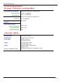
Firmware Update : You may use PC software provided on the CD-ROM and consult Internet site
www.aemc.com in the Tech Info section for available updates.
SCOPIX Oscilloscopes
3
General Instructions
General Instructions
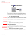
Introduction
You have just purchased a portable digital oscilloscope.
Congratulations on your choice and thank you for your trust in the quality of our
products.
This oscilloscope also offers the following modes:
• Multimeter Mode
• Harmonic Analyzer Mode (option)
• Recorder Mode (option)
It complies with safety standard NF EN 61010-1 (2001), double insulation, relative to
electronic measuring instruments.
For optimum service, read this manual carefully and comply with the operating
precautions.
Non-compliance with the warnings and/or operating instructions might damage the
instrument and/or its components and could prove dangerous for the user.
Precautions and
safety measures
• This instrument has been designed for use:
- indoors
- in an environment with pollution level 2,
- at an altitude of less than 2000 m,
- at a temperature between 32° 0°C and 40°C
- with relative humidity of less than 80% up to 31°C.
• The safety of any system integrating the apparatus concerns the
responsibility for the assembler for the system.
• It can be used for measurements on circuits 600 V, CAT III in relation to earth and can
be powered by a 98 to 240 V AC line.
However, some accessories can lead you to use this instrument on circuits of lower
voltage and category rating. Conform to these ratings when connecting the accessory.
In the event of use of different accessories, consider the lowest voltage and category.
Definition of
measurement
categories
CAT II: Measurement category II corresponds to measurements made on
circuits connected directly to the low-voltage installation.
Example: power supply for domestic appliances and portable
tools
CAT III: Measurement category III corresponds to measurements on
building installations.
Example: power supply for industrial machines or devices.
before use
• Comply with environmental and storage conditions.
• External power supply: it must be connected to the instrument and to the AC power
(from 98 to 264 VAC). Make sure that it is in good working condition.
during use
4
• Read carefully all the notes preceded by the symbol
.
• The instrument power supply is equipped with an electronic protection system,
which is reset automatically when the fault is eliminated.
• Be sure not to obstruct the ventilation holes.
• As a safety measure, use only suitable leads and accessories supplied with the
instrument or approved by AEMC® Instruments.
SCOPIX Oscilloscopes
General Instructions
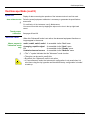
General instructions (cont'd)
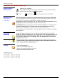
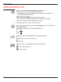
Warning: Risk of danger.
Refer to the operating manual to find out the nature of the potential hazards
and the action necessary to avoid such hazards.
Symbols used on
the instrument
Earth
Maintenance and
metrological
verification
Dual insulation
According to WEEE directive 2002/96/EC
Before the equipment is opened, it must be disconnected from the power supply and
the measurement circuits, and the operator must not become charged with any static
electricity. This could cause the damage to internal components.
Any adjustment, servicing or repair of the unit under power must be undertaken only by
qualified personnel, after reading the instructions in this manual.
A qualified person is a person who is familiar with the installation, its construction, its
use and the hazards that exist. They are authorized to activate and deactivate the
installation and equipment, in compliance with the safety instructions.
For information and contact details, contact the organization from which the instrument
was purchased.
Unpacking Repacking
Upon receiving your shipment, make sure that the contents are consistent with the
packing list. Notify your distributor of any missing items. If the equipment appears to be
damaged, file a claim immediately with the carrier and notify your distributor at once,
giving a detailed description of any damage. Save the damaged packing container to
substantiate your claim.
When the oscilloscope is delivered, the battery may be discharged and require a
complete recharge. Full charging of the battery will then take about two and a half
hours, with the oscilloscope switched off.
Cleaning
•
•
•
•
Turn the instrument off.
Clean it with a damp, soapy cloth.
Never use abrasive products or solvents.
Allow to dry before any further use.
NATO approved:
OX 7102CK - 6625 14 549 3558
OX 7104CK - 6625 14 549 3559
SCOPIX Oscilloscopes
5
Description of the instrument
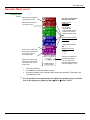
Description of the instrument
This manual describes the operation of an OX 7104 oscilloscope.
OX 7104 : the adjustment of the 4 channels is accessible by the keys shown to the left.
OX 7102 : the adjustment of the 2 channels is accessible by the keys shown to the left.
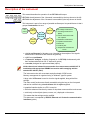
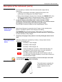
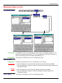
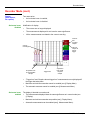
Presentation
This instrument is part of our range of portable oscilloscopes. Its special feature is that it
groups 4 instruments into one:
FFT
function
Digital
Oscilloscope
Multimeter
(RMS)
OX 7102
OX 7104
Harmonic
Analyzer
• DC voltage measurement
• AC voltage measurement
• Current measurement with
use of probes
Recorder
• Resistance measurement
• Capacitor measurement
• Diode test
• Continuity test
• Temperature measurement
PT100
• a digital oscilloscope for laboratory use, intended for the analysis of the signals
encountered in electronics and electrical engineering
• a 4000-count multimeter
• a "harmonic" analyzer, to display 2 signals (or 4: OX 7104) simultaneously with
their fundamental and their first 31 harmonics (option)
• a recorder, designed to capture trend data (option)
All the channels are isolated from one another for measurements on 600V CAT III
installations with appropriated PROBIX accessories while complying with the
standard IEC 61010-1 (2001).
The instrument works with a constant acquisition depth of 2500 counts.
Memory management is organized using a "Windows" type file system.
A large color LCD screen is used to view the signals applied, along with all the
settings.
The main control functions are directly accessible using the keys on the front panel
and can be modified using a touch-screen with the stylus supplied.
A graphical interface similar to a PC's is used to:
• select the advanced functions by means of drop-down menus and the touch-screen
• act directly on the objects (traces, cursors, etc.) displayed on the screen.
This means that the settings can be modified.
This instrument is completed by RS-232, Ethernet and Centronics communication
interfaces (option).
6
SCOPIX Oscilloscopes
Description of the Instrument
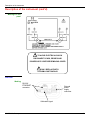
Description of the instrument (cont'd)
Markings on rear
panel
61010
ISOLATED
TO AVOID ELECTRICAL SHOCK
DISCONNECT LEADS, PROBES AND
POWER SUPPLY BEFORE REMOVING COVER
ONLY REPLACE WITH
9.6V NiMH CUSTOM PACK
Side view
Marking
RS-232/
ETHERNET
connector
External
power
supply
connector
Calibration signal
SCOPIX Oscilloscopes
7
Description of the instrument
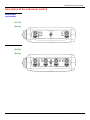
Description of the instrument (cont'd)
Measurement
terminal block
OX 7102
Marking
1
4
OX 7104
Marking
8
SCOPIX Oscilloscopes
Description of the Instrument
Description of the instrument (cont'd)
Front (description)
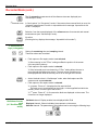
1 On/Standby/Off key
The main functions of the instrument are accessible on the front panel and can be
modified using the touch-screen (with its stylus) or the menu bar.
• power on by a short press
• switch the instrument to standby (yellow LED flashing inside the key) by one
short press. A second press on the key reactivates the instrument.
• power off by a long press (> 3 s): the configuration and files are saved after
approximately 15 s.
If the instrument is not equipped with a battery, never disconnect the instrument
from the AC power while the message "System shut down : Please wait before
switch off power" is displayed on the screen. Otherwise, the current file and all the
files previously saved will be lost.
1 touch-screen and
stylus
These can be used for:
selection of menus,
validation of functions,
movement of symbols appearing on the LCD screen.
• The menus at the top of the screen and the submenus selected by the pointer
open and are validated with the stylus.
• The menus in the curve display area,
the command area
the status area
can be opened with the stylus.
• The stylus can move the symbols displayed in:
1. the main display area:
trigger position
position of cursors
reference of the traces displayed
2. the bargraph:
trigger position
position of cursors
position of zoomed area in the acquisition memory
Place the pointer on the symbol to be moved and keep the stylus pressing down
while you move it to the required position.
• It is possible to use the stylus to zoom in the display area by dragging a box
around the area of interest.
4 "operating mode"
keys
You can select the operating mode of the instrument by pressing one of these 4 keys:
"oscilloscope"
"multimeter"
"harmonic analyzer" (option)
"recorder" (option)
28 keys only active
when pressed
Shortcut access to the most common functions: see chapter on "The Keys" for the
"Oscilloscope", "Multimeter", “Harmonic Analyzer” and “Recorder” modes.
SCOPIX Oscilloscopes
9
Description of the instrument
Initial operation of
the oscilloscope
The portable oscilloscope is designed to operate on a power source from 98 to
264 V (ACrms) at 50 to 60 Hz or in stand-alone mode with a battery.
The instrument is delivered with an AC power adapter, an external power supply
(battery charger) and an Ni-MH battery (9.6 V, 3.5 A/h).
Fuse
Type: time delay, 2.5 A, 250 V, 5 x 20 mm
The external power supply is equipped with a protection fuse that must only be
replaced with an identical model.
Replacement must only be performed by qualified personnel.
Contact your distributor or AEMC® for servicing.
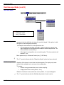
Starting up with
the external power
supply
• Connect the 4-pin lead of the external power supply to the "'DC-Input"
socket located on the side of the oscilloscope.
Do not insert any metal objects into this lead.
• Connect the power cord from the external power supply to the power line.
The POWER LED on the adapter lights up, indicating that it is live.
The CHARGE LED flashes, indicating:
• the absence of the battery or
• slow charging of the battery, if it is present in the oscilloscope.
Press the instrument's ON button: it lights up and a clock is displayed on the
screen during the start-up sequence.
The message "Instrument start-up" is displayed.
The oscilloscope is then ready for use.
By default, the "Advanced" mode is not active.
external power supply
The symbol
in the display area for the current value means that the
instrument is connected to the AC power supply.
10
SCOPIX Oscilloscopes
Description of the Instrument
Description of the instrument (cont'd)
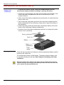
Installation of the
battery in the
oscilloscope
To prevent any electric shocks, remove the PROBIX adapters and the
external power supply lead before installing or replacing the battery.
• Using a coin or a screwdriver, turn each of the 2 plastic screws located on the
cover of the battery compartment at the rear of the instrument 1/4 turn
counter-clockwise.
• Lift the cover of the battery compartment by inserting the coin under the slot at
the top of the cover.
• Then connect the 4-pin battery connector to the connector located inside the
battery compartment of the oscilloscope, taking care to respect the polarity of
the connectors.
• Position the battery inside the oscilloscope compartment (battery wires at the
bottom of the oscilloscope's battery compartment).
• Close the cover of the battery compartment and lock it by turning the 2 plastic
screws 1/4 turn (clockwise).
Screw
Cover
Battery
Battery
compartment
Lower
casing
Changing the battery
Follow the same procedure and make sure that the replacement battery model is
identical to the original one.
The oscilloscope contains a Ni-MH battery. The dead or defective battery must
be recycled according to local laws. Never dispose of the battery with other
solid waste.
When the oscilloscope is delivered, the battery may be discharged and require a
complete recharge. Full charging of the battery will then take about two and a half
hours, with the oscilloscope switched off.
SCOPIX Oscilloscopes
11
Description of the instrument
Description of the instrument (cont'd)
Charging the battery
Once the battery is installed, follow the external power supply start-up
instructions.
• To speed up recharging of the battery, switch off the power to the
oscilloscope with a long press of the ON/OFF button.
• Battery fully discharged: during the first 10 minutes, the CHARGE LED of the
external power supply flashes, indicating that the battery is slow-charging.
The CHARGE LED then lights up when it switches to fast-charging.
During the charging of the battery (after 15 min), powering on of the
oscilloscope causes premature stopping of the charge. It is possible to restart
the charging by disconnecting, then reconnecting the charger.
The LED goes out when the battery is fully charged (approx. 2h30).
Charging the battery
while using the
oscilloscope
When the oscilloscope is connected to the AC power via the external power
supply, it is possible to perform slow-charging of the battery.
The CHARGE LED of the external power supply lights up. Full recharging of a
totally discharged battery then takes approx. five and a half hours. The LED goes
out when the battery is fully charged.
Frequently recharging a battery when it is not fully discharged reduces its life
span.
Powering the
instrument with the
battery
When the oscilloscope is powered by a battery, a charge status indicator
appears in the display area:
the battery is 100% charged
the battery is 80% charged
the battery is 60% charged, etc.
If only one charge bar is present, it means that the battery can
only operate for a few minutes more, so you are advised to
recharge it or switch to the AC power supply.
The battery is totally dead and the screen is about to shut off.
You must either recharge the battery or connect the instrument to
the external power supply.
To maintain good condition of the battery, use the oscilloscope until at least
one bar remains
before recharging.
Use of the stand
The oscilloscope is equipped with
a stand that can be used to tilt it
when it is placed on a work
surface.
12
SCOPIX Oscilloscopes
Description of the Instrument
Description of the instrument (cont'd)
Concept
The oscilloscope uses PROBIX intelligent probes and adapters, offering users
active safety.
When connected to one of the oscilloscope's inputs, a safety message
concerning the probe or adapter used indicates:
• its maximum input voltage according to the category
• its maximum voltage in relation to the ground, according to the category
• its maximum voltage between channels, according to the category
• its type
• its basic specifications
• the use of suitable safety leads.
For user and instrument safety, these instructions must be adhered to.
Some probes are equipped with buttons whose assignment can be programmed.
An interchangeable elastic band or plastic collar can be used to match the probe
color to the trace color.
The oscilloscope provides the power supply for the probes and adapters.
BNC Adapter:
PROBIX HX0031
SCOPIX Oscilloscopes
13
Description of the instrument
Description of the instrument (cont'd)
Banana adapter
∅ 4 mm :
PROBIX HX0033
The positive input is indicated by a + sign.
1/10 probe:
PROBIX HX0030
ÑoÒ
A
Buttons A and B on the probe can be used to directly modify the parameters of the
channel connected or to call the functions on the front panel of the oscilloscope (see
§. Vert Menu
chx
PROBIX).
The color of the trace can also be programmed in this menu.
B
Compensation
HF
The "ÑoÒ" button controls the lighting of the area to be measured.
14
SCOPIX Oscilloscopes
Description of the Instrument
Description of the instrument (cont'd)
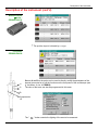
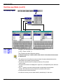
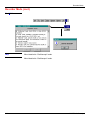
Connection
Disconnection
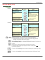
A window indicating the safety conditions is displayed when you connect or
disconnect a PROBIX adapter on one of the channels of the instrument:
General
specifications of the
adapter which has
been last connected
Input :
Max. voltage of the
signal measured
by the Probix
adapter
Floating input :
Acceptable max.
voltage on each
Probix input in
relation to earth
SCOPIX Oscilloscopes
Between channels :
Acceptable maximum
voltage between the
channels
(this voltage depends on
the combination of
connected Probix
adapters).
15
Description of the instrument
Description of the instrument (cont'd)
Recommendation for
use : Connection of
reference conductors
for the 1/10 PROBIX
HX0030 probe
1. To prevent electric shocks or possible fires, never use the grounding spring of
the 1/10 probe for voltages > 30 Vrms in relation to the ground.
2. Distribution of stray capacitances:
It is essential, given the stray capacitances, to connect properly the reference conductors
for each probe. These conductors must be connected preferably to the cold points, to
prevent transmission of noise by the stray capacitance between modes.
The noise of the digital ground is transmitted to the analog entry by the stray capacity.
16
SCOPIX Oscilloscopes
Description of the Instrument
Description of the instrument (cont'd)
Configuration of the "Network" interface (Ethernet).
This interface uses the same connector (RS-232/Ethernet), located on the right-hand
side of the instrument, and requires a specific Ethernet / RJ 45 cable.
Network
General principles
of the Ethernet
network
Addressing
Ethernet physical
addresses
IP addresses
Ethernet and TCP/IP (Transmission Protocol/Internet Protocol) are used to
communicate on a company's network.
Each piece of equipment under TCP/IP has a physical address (Ethernet) and an
Internet address (IP).
A physical or Ethernet address, stored in ROM or PAL, identifies each item of
equipment on the network. The physical address enables the equipment to determine
the source of data "packet" transmission.
The physical address is a number coded over 6 bytes represented in hexadecimal
form. Hardware manufacturers procure physical addresses and allocate them
incrementally when the product is manufactured. The physical addresses cannot be
modified.
An IP address is coded over 4 bytes, displayed in decimal format.
Example: 132.147.250.10). Each field may be coded between 0 and 255 and is
(
separated by a decimal point.
Unlike the physical address, the IP address can be modified by the user.
You must ensure that the IP address is unique on your network. If an address is
duplicated, network operation becomes random.
The IP address is made up of two parts:
• the network identifier (Network ID) identifying a given physical network
• the host identifier (Host ID) identifying a specific item of equipment on the
same network.
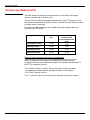
There are 5 addressing classes. Only classes A, B and C are used to identify the
equipment.
See below:
Class A
0XXXXXXX
XXXXXXXX
Network ID
XXXXXXXX
XXXXXXXX
Host ID
Class B
10XXXXXX
XXXXXXXX
Network ID
XXXXXXXX
XXXXXXXX
Host ID
Class C
010XXXXX
XXXXXXXX
Network ID
SCOPIX Oscilloscopes
XXXXXXXX
XXXXXXXX
Host ID
17
Description of the instrument
SUBNET mask
and GATEWAY
If the result of the operation ' AND LOGICAL' between IP address of the recipient of
the message and the value of subnet mask is different from the address of the
recipient of the message, this message is sent to the gateway which will be given
the responsibility to forward it to destination.
The programming of the mask and the address of the gateway is possible on the
instrument, in the Advanced mode.
DHCP Protocol
This protocol is used to automatically assign an IP address to the instrument when
it connects up to the network.
A DHCP (Dynamic Host Configuration protocol) server must be accessible on this
network (contact your network administrator to make sure that this server is
present).
FTP protocol
FTP (File Transfer Protocol) is used in the oscilloscope for fast file transfers to or
from a PC.
To use it, open the browser on the PC and, in the URL field, type the IP address of
the instrument, preceded by "ftp:"
Example: ftp://192.168.3.1
The oscilloscope is an FTP server.
See §. Applications.
HTTP protocol
With this protocol, the instrument can act as a WEB server and you can access the
most frequent settings and view traces on your PC using your browser (INTERNET
EXPLORER, NETSCAPE, …)
To use it, open the browser on the PC and, in the URL field, type the IP address of
the instrument, preceded by "http:"
Example: http://192.168.3.1
See §. Applications.
You must install Java Virtual Machine JVM SUN 1.4.1 (or higher) on your PC to be
able to display the traces. This JVM can be downloaded from the site
http://java.sun.com
LPD protocol
This protocol (Line Printer Daemon) is used by most of the printers connected to an
Ethernet network, but also by the printing server units which handle conversion
Example: Jet Admin) and UNIX and LINUX
between Ethernet and Centronics (
workstations.
An LPD server can also be installed on a PC (available as an option with
WINDOWS 2000 or XP).
In all cases, the instrument is an LPD client that has to be configured to indicate to
it the IP address of the LPD server (the workstation PC or directly the printer) and
the logical name of the printer managed by the server.
See §. Applications.
18
SCOPIX Oscilloscopes
Oscilloscope Mode
Oscilloscope Mode
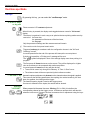
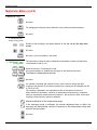
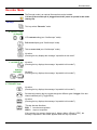
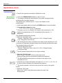
The Keys
By pressing this key, you can select the "oscilloscope" mode.
5 "UTILITY" keys
or key pad
Direct access to LCD contrast adjustment.
When this key is pressed, the display mode toggles between normal to "full screen"
display.
The screen is organized in such a way as to optimize the trace plotting surface area by:
removal of: the menu bar,
the parameters of the traces of the time base,
the bargraph.
Only the permanent settings and the measurements will remain.
The controls on the front panel remain active.
Triggers a hardcopy in accordance with the configuration chosen in the "Util" and
"Hardcopy" menus.
A second press before the end of the process will interrupt the current printout.
If printing is impossible, a "Printing error" message will be sent.
The "
" symbol is displayed in front of the settings display zone when printing is in
progress.
The first press will freeze the traces on the screen. They will be displayed in a lighter
color as a reference to be compared with another acquisition.
A second press will erase them: they will then be lost.
• Traces will be saved only through the "Memory
Trace
Save" menu.
• The reference data will be accompanied by their reference number.
1 "AUTOSET" key
Selective
"AUTOSET"
+
SCOPIX Oscilloscopes
Automatic optimum adjustment by Autoset on the channels where the signal is applied.
This concerns the following parameters: the coupling, the vertical sensitivity, the time
base, the gradient, the framing and the trigger.
The lowest frequency signal is used as the trigger source.
If no trace is detected on the inputs, the autoset will be aborted.
When pressed at the same time as a CHx key (CH1 to CH4), this defines the
corresponding channel as the trigger source. It initiates an autoset which will take this
selection into account. Channel CHx then becomes active for adjustment using the keys:
19
Oscilloscope Mode
Oscilloscope Mode (cont’d)
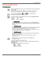
4 "Trigger" keys
Sets the trigger level to the average value of the signal (50%) without modifying the
trigger coupling.
When pressed in combination with a CHx key, this activates the same the same
function, after first selecting the corresponding channel as the trigger source.
selects the trigger gradient (up
or down
The gradient is indicated in the status area.
) by successive presses.
Successive presses can be used select one of the following acquisition modes:
Single shot
(Mono) = SINGLE
Triggered
Trig
Automatic
(Auto) = REFRESH
•
"SINGLE" mode:
A single acquisition is authorized, triggered by pressing the RUN HOLD key.
For any further acquisition, the trigger circuit must be reset by pressing the RUN
HOLD key.
•
"TRIGGERED" mode:
The screen's content is only refreshed when there is a trigger event linked to the
signals present on the oscilloscope's inputs (CH1, CH2, CH3, CH4).
If there is no trigger event linked to the signals present on the inputs (or if there
is no signal on the inputs), the trace is not refreshed.
•
"AUTOMATIC" mode:
The screen's content is refreshed even if the trigger level is not detected on the
signals present on the inputs.
When there is a trigger event, screen refreshing is managed as in the
"Triggered" mode.
• allows acquisition to be started and stopped in "TRIGGERED" and
"AUTOMATIC" modes.
• resets the trigger circuit in "SINGLE" mode.
Acquisition is initiated according to the conditions defined by the acquisition mode
(SGLE REFR key).
The acquisition status is indicated in the status area:
RUN
= started
STOP
= stopped
PRETRIG = acquisition
20
SCOPIX Oscilloscopes
Oscilloscope Mode
Oscilloscope Mode (cont'd)
3 "MEASURE" keys
Activates or deactivates the display of the window for the 19 automatic
measurements on the reference trace.
When pressed in combination with a CHx key, it displays the measurements
concerning the corresponding channel.
By means of successive presses, this selects one of the displayed traces as the
reference trace for the automatic and manual measurements.
It appears in the "Measure" menu
Reference.
Activates or deactivates the cursor display for manual measurements.
The cursors can be moved directly on the touch-screen using the stylus.
• The "dt" measurements (time difference between the two cursors)
and "dv" measurements (voltage difference between the two cursors) are
indicated in the status area.
• The absolute value of the cursor selected is indicated in the "Current
Settings” area.
3 "HORIZONTAL"
keys or key pads
Adjustment of the time base coefficient (T/DIV).
After a Zoom, the "Z-Pos." setting modifies the position of the screen in the
acquisition memory.
Activates or deactivates the "Zoom" function.
By default, the zoom is performed around the samples located in the middle of the
screen.
A zone can be zoomed by tracing a rectangle around the area to be enlarged
using the stylus on the touch-screen. The sensitivity, time base and horizontal and
vertical alignment values are recalculated automatically.
SCOPIX Oscilloscopes
21
Oscilloscope Mode
Oscilloscope Mode (cont'd)
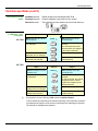
Definition of terms
used
5 "VERTICAL" keys
or key pads
OX 7104
Validated channel:
Displayed channel:
Selected channel:
Display enabled, trace displayed after RUN
Channel validated, trace present on the screen
The parameters of this channel can be set with the keys:
Step 1
Before pressing one of the
following keys :
Step 2
Press
The channel concerned is
not displayed.
and
Step 3
After pressing one of the
preceding keys:
The channel is displayed and
selected.
The vertical sensitivity and
vertical position are assigned
to the channel selected.
The channel is selected.
The channel concerned is
displayed, but not selected.
The channel concerned is
displayed and selected.
The channel is erased by
double-pressing.
OX 7102
Step 1
Before pressing one of the
following keys :
Step 2
Press
The channel concerned is
not displayed.
The channel concerned is
displayed, but not selected.
The channel concerned is
displayed and selected.
Step 3
After pressing one of the
preceding keys:
The channel is displayed and
selected.
On CH1 and CH4, the vertical
sensitivity and the vertical
position are assigned to the
channel selected.
The channel is selected.
The channel is erased by
double-pressing.
A long press on one of the keys CHx causes a vertical autoset:
• This modifies the sensitivity and vertical positioning of the channel in question.
• It optimizes the display on the screen by activating and selecting the channel.
The channel is displayed and selected.
22
SCOPIX Oscilloscopes
Oscilloscope Mode
Oscilloscope Mode (cont'd)
Activates or deactivates horizontal splitting of the display zone.
When activated, the "Full Trace" function is indicated by:
- the presence of a continuous horizontal line in the middle of the display area
- horizontal splitting of the graticule.
After activation of the function:
- traces 1 and 3 are assigned to the upper part of the display,
- traces 2 and 4 are assigned to the lower part in order to prevent overlays.
The traces can then be moved vertically in the two zones.
This function can also be used in "full screen" mode.
Successive presses allow selection of the input coupling (AC, DC or GND) for the
last channel selected.
The coupling is indicated in the channel parameters area:
AC :
DC :
GND :
Adjustment of the vertical sensitivity of the last channel selected:
increases the vertical sensitivity, while
reduces it.
Adjustment of the vertical position of the last channel selected:
moves it downwards, while
moves it upwards.
SCOPIX Oscilloscopes
23
Oscilloscope Mode
Oscilloscope Mode (cont'd)
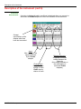
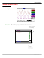
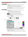
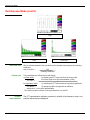
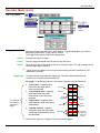
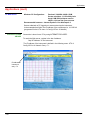
Display
Display
Cursor2
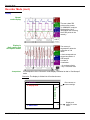
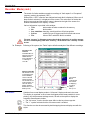
Composition
The oscilloscope display is divided into 4 functional zones.
Direct access to
main settings
4. Menu bar
2. Control area
3. Display area
1. Status area
Display and
adjustment of
current value
24
SCOPIX Oscilloscopes
Oscilloscope Mode
Oscilloscope Mode (cont'd)
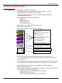
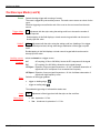
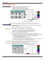
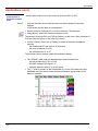
1. Status area
Three types of general information appear in this area:
• The bargraph representing the screen position, the trigger and the
cursors in the acquisition memory.
• The instrument permanent settings.
• The measurements, when the cursors are present on the screen.
Bargraph
Cursor measurements
Representation and
movement of the screen in
acquisition memory
(1)dt=110,0µs, div=100.0µV
Movement towards left of
screen in acquisition
memory
1
Trig
Permanent settings
1 Pretrig
2
T
Position and movement
of time trigger
Position and movement of
manual cursors
Movement towards right of
screen in acquisition
memory
Each element in the bargraph can be moved with the stylus.
This zone refers to the trigger status (mode, edge, source, current status).
Permanent settings
Example: AUTO
1 STOP
When the stylus is placed on this information, the "Trigger Parameters"
menu can be opened by pressing twice.
Cursor
measurements
This zone refers either to:
• the horizontal (dt) and vertical (dv) differences between 2 cursors in the
case of manual measurements
Example: (1) dt = 110.0 µs, div = 100.0 µV
• phase measurement in the case of manual phase measurement (Ph).
Example: (1) Ph = 200.0°
• the automatic measurements selected using the "Automatic
Measurements" or "Phase measurement" menus
Example: (2) F = 1.0000 kHz, Vpp = 7,500 V
SCOPIX Oscilloscopes
25
Oscilloscope Mode
Oscilloscope Mode (cont'd)
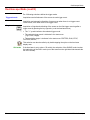
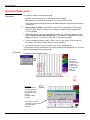
2. Control area
The parameters displayed in this area are:
• The parameters of each channel and trace: display, sensitivity, coupling,
bandwidth limitation, vertical scale, function, Zoom.
• The time base value, the presence of a Zoom and a change in the signal
representation domain (FFT).
• Active adjustment of the last selected element:
- trigger level
- trigger time position
- channel offset value
- X & Y position of cursor
• Time display, if no measurement has been selected.
• Display of the battery status
• A plug if the instrument is connected to the Wall Plug.
Display of the trace parameters (in the
color of the trace):
validity, coupling, bandwidth limitation,
sensitivity
Display of ZOOM mode
or
Display of the math function parameters
(in the color of the trace):
validity, value of one division
Display of ZOOM mode
or
Display of memories (M): validity
Value of time base coefficient (s/div) in
oscilloscope mode or of the frequency
(Hz/div) in FFT mode
Contrast
25.0 %
Change of signal representation domain
(FFT selection)
Indication and adjustment of last setting
selected
• The channels and functions can be validated using the stylus or the keys.
• The " " symbol indicates whether a channel or function is selected, or whether FFT
mode is selected.
• The settings of the time base (or the frequency) and the value of the active parameter
can be modified using the UP/DOWN button next to the display of the current value.
• After modification of the time base, the corresponding sampling frequency is
indicated in the settings area.
• When the stylus is placed on the parameters or a channel or on the value of the time
base, it directly opens the associated menus:
- Sensitivity/Coupling and Vertical Scale, for the channels
- Vertical scale for the functions
- Source, trigger mode and RUN/STOP, for the time base.
26
SCOPIX Oscilloscopes
Oscilloscope Mode
Oscilloscope Mode (cont'd)
The grouped "Source" and "Trigger Mode" menus can be opened by a double press
with the stylus on the time base area.
RUN/STOP starts and stops acquisition from this menu. The acquisition status is
indicated in the status area on the screen.
The symbol " " indicates the source and trigger mode selected.
3. Display area
The graphic elements displayed associated with the traces in this area are:
• a trigger time position indicator
• a trigger level indicator
• a trace number identifier
• a vertical position indicator for the reference level of each trace
• cursor position indicators linked to the trace for the automatic measurements
• position indicators regarding the cursors linked or not to the trace
for manual measurements
• selection of a zoom zone
SCOPIX Oscilloscopes
27
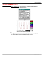
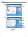
Oscilloscope Mode
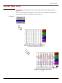
Oscilloscope Mode (cont.)
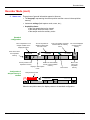
Display elements
3
6
>
1
10
2
ϕ
8
5
6
2
1
v
12
Definition of display
v
4
Refs.
7
9
11
Elements selectable using the touch-sensitive pad
Trace displayed
1
Trace2 displayed
Vertical position indicator of the reference level of the trace displayed
and identification of the trace number
28
3
Indication of Trigger time position
4
Division of graticule
5
Position indicator of the cursors for the first automatic measurement
6
Manual measurement cursor position indicator
7
Phase measurement cursor position indicator
8
Trigger level position indicator
9
Selection of a zoom zone
10
Indicator of trigger time position overshoot outside the display
window
11
Indicator of trigger level position overshoot outside the display
window.
12
Indicator of channel level overshoot outside the display window.
SCOPIX Oscilloscopes
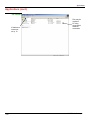
Oscilloscope Mode
Oscilloscope Mode (cont.)
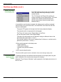
Menu accessible
from display area
By double-tapping with the stylus in the display
area, the menu concerning the display can be
opened directly.
The "Full Screen" and "Zoom Out" options are
directly accessible (see § Display Menu). The same
applies to the selection of the automatic and
manual measurement reference signal (see §
Measure Menu).
It is possible to use the stylus to zoom in the display area by pulling a rectangle.
After zooming in on part of the screen, the sensitivities of the traces and the time
base are recalculated.
The symbol "Z" appears in the signal and time base parameters display.
The zoomed section is represented in the bargraph.
The "Zoom Out" menu (see §. Display Menu) or the Zoom
key can be used to return to the original display.
The value of the horizontal zoom is adjusted to assign a calibrated value to the
horizontal scale (zoom factor: x 5 max.)
If the vertical selection of the zoom is greater than 6 divisions, no vertical zoom is
performed (zoom factor: x 16 max.).
All the symbols present in the display area:
- trigger indicators,
- trace position indicator,
- manual cursor position indicator,
- etc.
can be moved using the stylus.
The new modified symbol value is indicated in the current settings display area.
Calibration of the
touch-sensitive
screen
SCOPIX Oscilloscopes
To optimize selection of the different elements present in the display area using the
stylus, calibration of the touch-screen may prove necessary.
Select the "Touch Screen Calibration" option proposed in the display area menu or in
the Util. menu.
29
Oscilloscope Mode
Oscilloscope Mode (cont.)
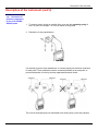
Calibration of the
touch-screen
(cont'd)
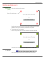
Follow the instructions on the screen
Corner of the touch screen
Use the stylus to point at the centre of the 4 patterns displayed on the screen.
Validation of the input is indicated by modification of the pattern.
The pointing order is not important.
Once the 4 inputs have been recorded, validate the calibration with OK.
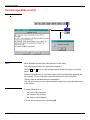
The touch-screen is calibrated and the display returns to normal mode.
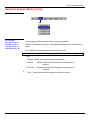
4. Menu bar
All the oscilloscope functions can be accessed via the main menus.
30
SCOPIX Oscilloscopes
Oscilloscope Mode
Oscilloscope Mode (cont'd)
The "Vert" Menu
(∗)
(∗)
(∗)
(∗)
(∗) Functions only accessible in
"Advanced" mode.
See §. Description.
SCOPIX Oscilloscopes
31
Oscilloscope Mode
Oscilloscope Mode (cont'd)
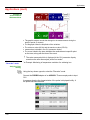
Display
Opens the "Trace display" menu for validating or devalidating the traces.
Validation of the selections by "OK". Exit from the menu without modification
by "Cancel".
The " " symbol in front of a trace indicates that it has been validated.
The traces can be validated or devalidated from the control area by using the stylus.
ch1 ch2 ch3 ch4
Sensitivity / Coupling
Channel Sensitivity
Coupling
Modify the parameters of channels ch1, ch2, ch3 and ch4 independently, as well as the
vertical scale of the trace selected.
Modifies the parameters of the selected channel.
Modification of the channel's sensitivity using the stylus on the scrollbar, adjustable by
sequence: from 2.5mV to 200V/div.
The sensitivity is indicated in the channel parameter display area. It takes into
consideration the parameters of the "Vertical scale" menu.
Modification of AC - DC - GND coupling
AC: blocks the DC component of the input signal and attenuates the signals below 10Hz
DC: transmits AC and DC components of the input signal
GND: internally, the instrument links the input of the channel selected to a 0 V
reference level.
The " " symbol indicates the coupling selected. Coupling is indicated in the modified
channel's parameter display area.
bw limit
Limits to 20MHz the bandwidth of the channel and its trigger circuit to reduce display
noise and false triggering.
The bandwidth of each channel can be limited to 5 kHz, 1.5 MHz or
20 MHz. The bandwidth limit of a channel is indicated in the control area by following
symbols :
20 MHz
1.5 MHz
5 kHz
This menu can also be called up by double-tapping with the stylus on the required
channel parameter display area.
Vertical scale
Coefficient
Defines the vertical scale of the channel selected on the basis of the current settings.
Readings of the direct measurements of the value analyzed and its unit are provided.
Assignment of a multiplication coefficient to the selected channel's sensitivity.
This can be modified with the stylus, using the table of usable numbers, after selecting
the "Coefficient" zone.
The
key deletes the character preceding the cursor in this area.
The predefined values (x1, x10, x100, x1000) correspond to standard probe coefficients
and can be assigned directly.
The sensitivity value indicated in the channel parameter display will be modified
according to this coefficient.
32
SCOPIX Oscilloscopes
Oscilloscope Mode
Oscilloscope Mode (cont'd)
Measurement unit
Modification of the selected channel's vertical scale unit.
The modification is performed by means of the stylus, using the table of usable
characters after selecting the “measure unit” zone.
The
key deletes the character preceding the cursor in this area.
The vertical scale unit will be indicated in the modified channel's parameter display.
Init
Reinitializes the multiplication coefficient to 1.00 and returns to the V measurement unit.
Validation of the selections by "OK". Exit from the menu without modification by "Cancel".
This menu can also be called up by double-tapping the stylus on the required channel's
parameter display area (CH1, CH2, CH3 or CH4).
PROBIX
ÑoÒbutton
Buttons A and B
When selected, this opens the "Probe Configuration" menu.
When a PROBIX HX0030 probe is connected to one of the oscilloscope's inputs, this
menu becomes active.
can be used to switch the LED on or off.
can be assigned to different settings (see table below).
Button B
Button A
ÑoÒ
Sensitivity
Higher sensitivity
Lower sensitivity
Vertical/horizontal
alignment
Alignment on higher
division
Alignment on lower division
Time base
Higher time base
Lower time base
Trig. edge / Run-Hold
A
B
Auto Meas. Ref. Meas.
AUTO MEAS. CHx
REF MEAS.
Autoset CHx / Auto 50 %
Auto CHx
AUTO 50% CHx
•
•
•
Color
RUN HOLD
See the chapter on "The Keys" for further details on the function provided.
The modified parameters are updated in the control area.
The “ " symbol indicates the parameters elected and assigned to the probe.
modifies the color that you want to assign to the trace.
•
•
The “ " symbol indicates the color selected.
•
If a PROBIX HX0031 BNC adapter or PROBIX HX0033 "banana" adapter is
connected to one of the oscilloscope's inputs, only the color menu is active.
These parameters will be memorized in the probe, even after disconnection of the
oscilloscope.
When using PROBIX adapters, the choice of the color remains possible.
SCOPIX Oscilloscopes
33
Oscilloscope Mode
Oscilloscope Mode (cont'd)
math1 math2 math3
math4
Function definition
For each trace, definition of a mathematical function and the vertical scale.
Menus present only in Advanced mode (see §. "Util" Menu).
Defines the mathematical function to be assigned to the selected trace by means of
a vertical keyboard, linking traces ch1 and ch2, as well as ch3 and ch4 if
necessary.
• The mathematical function can be defined on 2 lines.
• ch2 and ch3 can only be used on OX 7104 oscilloscope.
• mathx cannot be used in the definition of a function.
The
Functions
key deletes the character preceding the cursor in the window.
8 predefined mathematical functions can be linked to the traces:
divh(
("horizontal division")
divv(
("vertical division")
step(
("step") using "t" (∗)
sin(
("sine")
cos(
("cosine")
exp(
("exponential")
log(
("logarithmic")
sqrt(
("square root")
(∗) t = abscissa of the sample in the 2500-sample acquisition memory.
divh(1) is equivalent to 250 samples (counts) = 1 horizontal division
Validation of the selections by "OK". Exit from the menu without modification by
"Cancel".
If …
then …
... the dynamic calculation of the
vertical scale is impossible
... a message indicates that the
measuring unit on this function will
be vertical division (div).
... the dynamic calculation of the vertical
scale is possible
... it takes into account of the
sensitivities of the channel sources.
Particular cases :
Value of the measuring unit
CHx + CHy
Sensitivity and measuring unit used on CHx
CHx - CHy
Sensitivity and measuring unit used on CHx
In each cases, the measuring unit can be re-defined and a coefficient can be applied
to the measurement results (refer to §. Vertical scale).
34
SCOPIX Oscilloscopes
Oscilloscope Mode
Oscilloscope Mode (cont'd)
Examples
Use of predefined
mathematical
functions
•
Predefined divv() function used on its own: math3 = divv(3).
The trace is equal to 3 vertical divisions.
• Predefined step() function associated with a trace:
- math2 = ch1*step(t-divh(4))
The result of math2 is 0 vertical divisions as long as t is less than four
horizontal divisions (t-divh(4) < 0).
The result of math2 is equal to ch1 when t becomes greater than four
horizontal divisions (t-divh(4) > 0).
- math2 = ch1*step(divh(4)-t)
The result of math2 is equal to ch1 as long as t is less than four horizontal
divisions (t-divh(4) > 0).
the result of math2 is at 0 vertical divisions when t becomes greater than four
horizontal divisions (t-divh(4) < 0).
SCOPIX Oscilloscopes
35
Oscilloscope Mode
Oscilloscope Mode (cont'd)
Example 1
Addition of two
traces
Vhigh
Vpp(ch1) = Vpp(ch2) = 6 V
Sensitivity (ch1) = 1 V/div
Sensitivity (ch2) = 1 V/div
Traces ch1 and ch2 are optimised on 6 vertical divisions.
Vamp ch1 = 6 vertical divisions
Vamp ch2 = 6 vertical divisions
- math3 = ch1+ch2
Vertical scale math3 = 2.00 div
Vpp math3 = 12.00 div
Vhigh math3 = 6.00 div
There is a high and low overshoot, so division by 2 is necessary to optimize
display of the result.
- math3 = (ch1+ch2) / 2
Vertical scale math3 = 2.00 div
Vpp math3 = 12.00 div
Vhigh math3 = 6.00 div
Division by two adjusts the addition to the dynamics of the screen.
Vamp math3 = 6 vertical divisions
The measuring unit and the sensitivity of ch1 are used during the display of
measurements.
You can then open the menu “Vertical Scale" of math3 (see §. Opening from
math3, math4) to assign a coefficient to the result and to modify the measuring
unit.
36
SCOPIX Oscilloscopes
Oscilloscope Mode
Oscilloscope Mode (cont'd)
Example 2
Multiplication of
two traces
Sensitivity(ch1) = 5 V/div
Sensitivity(ch2) = 5 V/div
Vamp(ch1) = Vamp(ch2) = 10 V
Vamp ch1 = 2 vertical divisions
Vamp ch2 = 2 vertical divisions
- math3 = ch1*ch2
As for the addition of traces, there is a even more significant high and low overshoot.
The overshoot is due to the increased dynamics of the numbers after a
multiplication ; to avoid this and standardize the result, use the divv () function.
Example: If Amplitude on CH1 = 2 divv and Amplitude on CH2 = 2 divv, the following
function is used to get an amplitude of 1 divv :
math3 = (ch1 * ch2) / divv (1)
The result of the multiplication is translated into divisions on the screen.
- If Vamp ch1 = 8 div and Vamp ch2 = 8 div, the result
must be divided by divv(4) to obtain Vamp math3 = 4 div.
- When mathematical functions associated with traces are used, the
dynamics of the result obtained must be verified.
Correction of the result of the operations by mathematical functions (divv(), divh(), / …)
is recommended to optimize the screen display.
SCOPIX Oscilloscopes
37
Oscilloscope Mode
Oscilloscope Mode (cont'd)
You can then open the menu “Vertical Scale" of math3 (see §. Opening from
math3, math4) to assign a coefficient to the result and to modify the measuring
unit.
In our example:
• Then select math3 as the reference for the automatic and manual
measurements (see §. "MEASURE" Menu).
• Then display the table of 19 measurements made on the math3 trace
math3 (see §. "MEASURE" Menu).
The measurements displayed are the exact result of the multiplication of the two
traces ch1 and ch2 in the unit (V).
Sensitivity(math3) = 25 VV
Vpp (math3) = 25 VV
38
SCOPIX Oscilloscopes
Oscilloscope Mode
Oscilloscope Mode (cont'd)
Example 3
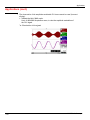
- math3 = divv(3)*sin (2*pi*t/500).
Association
of predefined
functions
The trace obtained is a sine-curve produced using the predefined function "sin()".
The amplitude is 6 divisions.
The period equal to 500 samples (2 horizontal divisions) depends on the time base.
• Same trace produced with the predefined divh() function:
math3 = divv(3)*sin(2*pi*t/divh(2))
In this example, divh(2) is equivalent to 500 samples.
1 horizontal division = 250 samples
The period divh(2), equal to 500 samples (2 horizontal divisions), depends on the
time base.
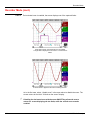
• Production of a sine wave by the predefined cos() function:
math3 = divv(3)*cos(2*pi*t/divh(2))
The trace obtained with the predefined cos() function is offset by 90°.
SCOPIX Oscilloscopes
39
Oscilloscope Mode
Oscilloscope Mode (cont'd)
Production of an
attenuated sine
wave using
predefined
functions
math1 = sin (pi*t/divh(1))*exp(-t/divh(6))*divv(4)
"sin (pi*t/divh(1))" can be used to modify the number of periods.
"exp (-t/divh(6))" can be used to modify the level of attenuation.
40
SCOPIX Oscilloscopes
Oscilloscope Mode
Oscilloscope Mode (cont'd)
Function definition
Files
Contains the list of the functions (.FCT) saved by the user, along with two predefined
files.
By selecting the name of the function with the stylus (function name in blue), you
can transfer the definition of the function into the 2 lines provided for that purpose.
The scroll bar can be used to scroll through the list of memorized functions.
The function can be modified with the table of usable characters, associating the ch1
and ch2 traces.
This menu also contains two predefined functions.
C1MULC2.FCT and SQUARE.FCT
C1MULC2 .FCT
Product of 2 traces with scaling:
math3 = ch1*ch2/divv(4) = C1MULC2.FCT
The factor divv(4) is used to optimize the display as long as the source signals have
sufficient dynamics (> 6 divisions) and no overshooting.
SQUARE .FCT
Definition of a square signal using first 4 harmonics of a Fourier series development.
math3 = SQUARE.FCT
math3 = (sin(pi*t/divh(2)) + sin(3*pi*t/divh(2))/3 + sin(5*pi*t/divh(2))/5
+ sin(7*pi*t/divh(2))/7)*divv(4)
SCOPIX Oscilloscopes
41
Oscilloscope Mode
Oscilloscope Mode (cont'd)
Save
Reset
Saves the definition of the function using the “File Copy “ menu (see §. Memory Menu).
The file is assigned the suffix .FCT and appears in the list of saved files.
Completely resets the function definition.
After assigning a function to the ch1 (math1), ch2 (math2), ch3 (math3) or ch4 (math4)
channels, "mathx" appears in the corresponding channel's parameter display area.
Vertical scale
Definition of the vertical scale for the selected trace
Calling this menu from math1 to math4 is identical to calling ch1 to ch4 as long as the
functions have not been defined.
Opening of the menu
from:
math1 math2
math3 math4
Coefficient
Modifies the value of a division (div) in the selected trace.
This can be modified with the stylus, using the table of usable numbers, after selecting
the "Coefficient" zone.
The
key deletes the character preceding the cursor in this area.
The predefined values (x1, x10, x100, x1000) correspond to standard probe coefficients
and can be assigned directly.
The value of a division will be entered into the display of the modified trace parameters.
Measurement unit
Modification of the unit of the vertical scale (div) for the selected trace.
This can be modified with the stylus, using the table of usable numbers, after selecting
the measurement unit zone.
The
key deletes the character preceding the cursor in this area.
The "±" key can be used to switch between upper-case and lower-case characters.
The vertical scale unit will be entered into the modified trace's parameter display (3
characters max).
Init
Reinitialization of the multiplication coefficient to 1.000 and return to the V measurement
unit.
Validation of the selections by "OK". Exit from the menu without modification by
"Cancel".
The "Vertical scale" menu can also be called up by double-tapping with the stylus in the
parameter display of the required trace (math1 to math4).
42
SCOPIX Oscilloscopes
Oscilloscope Mode
Oscilloscope Mode (cont'd)
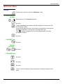
The "Trig" Menu
SCOPIX Oscilloscopes
43
Oscilloscope Mode
Oscilloscope Mode (cont'd)
Definition
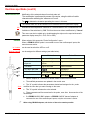
This range of portable oscilloscopes is equipped with "advanced triggers".
• The "Main" tab can be used to choose and parameterize the main
trigger source.
• The "Delay" and "Count" trigger modes require parameterization of a
second "auxiliary" trigger source. The auxiliary source may be the same
as the main source.
The trigger choice is validated by exiting from the menu.
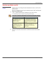
If …
then …
… the user exits from the
"Main" tab,
… "Main" triggering is used.
… the user exits from the
"Pulse" tab,
… "Pulse" triggering is used.
etc.
etc.
•
There is only one Holdoff, although it can be programmed from the
"Main", "Delay", "Count" or “TV” tabs.
When you use "Delay" or "Count", the Holdoff applies to the auxiliary
source, i.e. the source of the count pulses or delay trigger pulses.
In the other cases, Holdoff applies to the main trigger source.
•
Each trigger source has its own specific attributes: Coupling, Level,
Edge, Noise Reject, Filter.
You can also
choose the
trigger channel
by doubletapping with the
stylus in the
time base
display area.
You can also choose the trigger
parameters by double-tapping with the
stylus in the display area of the trigger
parameters.
44
SCOPIX Oscilloscopes
Oscilloscope Mode
Oscilloscope Mode (cont'd)
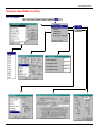
Parameters
Selection of the "Trigger Parameters".
Main
Source
Coupling
Trigger on edge
Selects a channel as a trigger source.
Selection of the filter for the main trigger source:
AC
AC coupling (10 Hz to 200 MHz): blocks the DC component of the signal
DC
DC coupling (0 to 200 MHz): allows the entire signal through
LF Reject Rejection of source signal frequencies < 10 kHz: facilitates observation of
signals with a DC component or an unwanted low frequency
Edge
HF Reject Rejection of source signal frequencies > 10 kHz: facilitates observation of
signals with high-frequency noise.
Selection of the trigger gradient:
+ leading trigger edge
-
trailing trigger edge
The selected trigger edge is indicated the status area.
Level
2.04V Adjustment of the trigger level with the stylus on the scroll bar.
The trigger level is entered into the current value display area after modification. Fine
adjustment is possible.
Noise reject
No: hysteresis ≈ 0.5 div.
Yes: introduces a hysteresis of ≈ 1.5 div.
Holdoff
108µs allows:
• disabling of the trigger for a predefined period
• stabilization of the trigger on pulse trains.
Double-tapping in this field displays a virtual numeric keypad which can be used to
directly input the value.
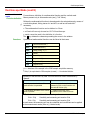
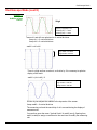
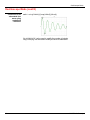
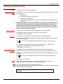
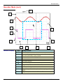
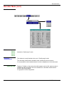
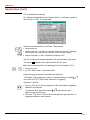
Example
SCOPIX Oscilloscopes
Signal injected on CH1: a train of three 6 VDC pulses at a frequency of 20 kHz with
a 500 mVDC component, separated by 500 µs.
45
Oscilloscope Mode
Oscilloscope Mode (cont'd)
Principal (suite)
Pulse
The trigger is regulated with channel 1 as a source, level at 2.04 V, on a
rising edge.
The Holdoff stabilizes the signal by inhibiting the trigger during 108 µs.
The DC coupling of the trigger lets the whole signal through.
In this example, the signal is not being disturbed and the option of noise
reject is not necessary.
The DC coupling of ch1 reveals the continuous component of the signal.
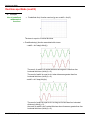
Selection of pulse-width trigger. In all cases, the effective trigger occurs on the
pulse trailing edge.
<
=
>
triggers on a pulse if its duration is less than the value set
triggers on a pulse if its duration is equal to the value set
triggers on a pulse if its duration is greater than the value set
25.0 µs Adjustment with the stylus using the time setting scroll bar
Double-tapping in this field displays a virtual numeric keypad which can be used
to directly input the value.
The choice of the
analysis:
Example
or
edge in the "Main" tab defines the limits of the
• edge
defines a pulse between
and
• edge
defines a pulse between
and
Signal injected on CH1: 1 pulse of 50 µs (repetitive or not)
The trigger parameters in the main menu are active (Source, Level, Edge, etc.).
The oscilloscope is triggered when the signal's pulse width is equal to the specified
pulse width (25.0 µs + tolerance).
The trigger occurs on the leading edge of the pulse, but is effective on the trailing edge.
Oscilloscope Mode (cont'd)
46
SCOPIX Oscilloscopes
Oscilloscope Mode
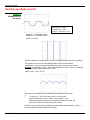
Delay
Selection of edge trigger with delay
The delay is triggered by the auxiliary source.
Effective triggering occurs after the end of the delay on the next event from the main
source.
35.2µs
Trigger delay
Adjustment with the stylus using the setting scroll bar to choose the
required delay value.
Double-tapping in this field displays a virtual numeric keypad which can be used to
directly input the value.
108ns Adjustment with the stylus using the setting scroll bar, allows disabling of the
trigger for a predefined period and, among other things, stabilization of the trigger on
pulse trains.
Holdoff
Double-tapping in this field displays a virtual numeric keypad which can be used to
directly input the value.
Auxiliarysource
Coupling
selects the channel as the trigger source.
AC
AC coupling (10 Hz to 200 MHz): blocks the DC component of the signal
DC
DC coupling (0 to 200 MHz): allows the entire signal through
LF Reject Rejection of source signal frequencies < 10 kHz: facilitates observation of
signals with a DC component
HF Reject Rejection of source signal frequencies > 10 kHz: facilitates observation of
signals with high-frequency noise.
Level
2.04V
Edge
selects the edge for the auxiliary trigger source:
Noise reject
Adjustment of the trigger level with the stylus on the scroll bar.
+
leading trigger edge
-
trailing trigger edge
No: hysteresis ≈ 0.5 div.
Yes: introduces a hysteresis of ≈ 1.5 div.
SCOPIX Oscilloscopes
47
Oscilloscope Mode
Oscilloscope Mode (cont'd)
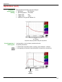
Example
Signal injected on CH1: a train of three 6 VDC pulses at a frequency of 20 kHz
separated by 500 µs.
The trigger is active after the end of the delay (35.2 µs) on the first leading edge.
The Holdoff stabilizes the signal by disabling the trigger for 108 µs.
48
SCOPIX Oscilloscopes
Oscilloscope Mode
Oscilloscope Mode (cont'd)
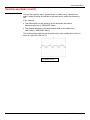
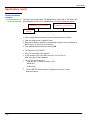
Count
Selects the edge trigger with counting of events.
The count is triggered by the auxiliary source. The main source serves as a clock for the
count.
Effective triggering occurs after the end of the count on the next event from the main
source.
3 Adjustment with the stylus using the setting scroll bar to choose the number of
events required.
Trigger delay
Double-tapping in this field displays a virtual numeric keypad which can be used to
directly input the value.
Holdoff
232µs Adjustment with the stylus using the setting scroll bar, disabling of the trigger
for a predefined period and, among other things, stabilization of the trigger on pulse
trains.
Double-tapping in this field displays a virtual numeric keypad which can be used to
directly input the value.
Auxiliary source
Coupling
selects a channel as a trigger source.
AC
AC coupling (10 Hz to 200 MHz): blocks the DC component of the signal
DC
DC coupling (0 to 200 MHz): allows the entire signal through
LF Reject Rejection of source signal frequencies < 10 kHz: facilitates observation of
signals with a DC component or an unwanted low frequency
HF Reject Rejection of source signal frequencies > 10 kHz: facilitates observation of
signals with high-frequency noise.
Edge
Selection of the trigger gradient:
+
trigger on leading edge
-
trigger on trailing edge
The selected trigger edge is indicated the status area.
Level
Noise reject
SCOPIX Oscilloscopes
1.09V
Adjustment of the trigger level with the stylus on the scroll bar.
•
No: hysteresis ≈ 0.5 div.
•
Yes: introduces a hysteresis of ≈ 1.5 div.
49
Oscilloscope Mode
Oscilloscope Mode (cont'd)
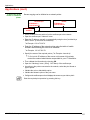
Example
Signal injected on CH1: a train of five 6 VDC pulses at a frequency of 20 kHz
separated by 500 µs.
The trigger is set on the trailing edge.
The first edge activates the trigger. It is not included in the count.
The trigger is triggered on the third trailing edge of the pulse train.
The Holdoff stabilizes the signal by disabling the trigger for 232 µs.
50
SCOPIX Oscilloscopes
Oscilloscope Mode
Oscilloscope Mode (cont'd)
TV
Standard
Polarity
Hodoff
Line
Trigger on a TV signal
See Chapter VI - Applications: §. Video signal display.
This menu is only applicable to the CH1 input.
Trigger on a specific line number. The trigger starts on the front edge of the line
synchronization signal.
• 625 lines (SECAM) or
• 525 lines (PAL)
+
Direct video
- Reverse video
Adjusted by scrolling with the stylus. Triggering impossible for a pre-defined time.
Double-tapping in this field displays a virtual numeric keypad which can be used to
directly input the value.
25
Adjustment of the no. with the stylus using the scroll bar.
Double-tapping in this field displays a virtual numeric keypad which can be used to
directly input the value.
The " " and “ ” symbols indicate the selected parameters.
Validation of the selections by "OK".
The "Trigger Parameters" menu can also be called up by double-tapping the stylus in
the trigger settings display area.
SCOPIX Oscilloscopes
51
Oscilloscope Mode
Oscilloscope Mode (cont'd)
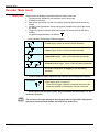
The 3 following selections define the trigger mode:
Triggered mode
Automatic mode
Single mode
Acquisitions and refreshment of the screen at each trigger event.
Acquisition and automatic refreshing of screen even when there is no trigger event.
Visible traces, even when there is no trigger event.
Acquisition of signal and refreshing of the screen on the first trigger occurring after a
trigger reset by pressing the key opposite (or via the time base menu).
• The " " symbol indicates the selected trigger mode.
• The selected trigger mode is indicated in the status area
(Trig'd, Auto, Single).
• The acquisition status is indicated in the status area: PRETRIG, RUN, STOP,
POSTRIG, READY, …
This selection can also be called up by double-tapping the stylus on the time base
display area.
Roll mode
52
If the time base is set to value > 50 ms/div, the activation of the SINGLE mode involves
the interlocking of the ROLL mode (run of the trace from the right-hand side towards the
left of the screen).
SCOPIX Oscilloscopes
Oscilloscope Mode
Oscilloscope Mode (cont'd)
The "Horiz" Menu
(∗)
(∗)
(∗) Function accessible only in
"Advanced" mode.
See §. Description.
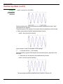
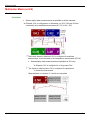
Repetitive Signal
Increase in the time definition of a trace for a periodic signal. If this option is valid,
the signal can be averaged (see below).
Example: measurement on a microprocessor bus.
•
For time bases of less than 100 µs/div. (without mode zoom active), the
signal displayed is reconstituted on the basis of several acquisitions. The
time resolution can reach 20 µs.
•
If the signal is not repetitive, do not use this option. The time resolution will
then be ± 1 ns.
Menu present only in "Advanced" mode (see §. "Util" Menu).
The " " symbol indicates that the "Repetitive Signal" option has been selected.
Min/Max Acquisition
Sampling of the signal, even at slow time-base speeds. The display only takes
extreme value samples (min. and max.) into consideration.
This mode:
• detects wrong representation due to under-sampling
• displays short-term events (Glitch, ≥ 2 ns).
Whatever time base is used, short-term events (Glitch, ≥ 2 ns) are displayed.
The " " symbol indicates that the "Min/Max Acquisition" mode is active.
SCOPIX Oscilloscopes
53
Oscilloscope Mode
Oscilloscope Mode (cont'd)
Averaging
No averaging
Average rate 2
Average rate 4
Average rate 16
Average rate 64
Selection of a coefficient to calculate an average for the displayed samples.
For instance, this is a way of attenuating random noise observed in a signal.
For the averaging coefficient to be taken into account for representation of the signal,
the "Repetitive signal" option must be selected.
The calculation is performed using the following formula:
Pixel N = Sample*1/Average rate + Pixel N-1 (1-1/Average rate)
with:
Sample
Value of new sample acquired at abscissa t
Pixel N
Ordinate of pixel with abscissa t on the screen, at moment N
Pixel N-1
Ordinate of pixel with abscissa t on screen, at moment N-1
The " " symbol indicates the averaging coefficient selected.
FFT
(Fast Fourier
Transform)
The Fast Fourier Transform (FFT) is used for calculating the discrete representation of a
signal in a frequency domain from its discrete representation in the time domain.
FFT can be used in the following applications:
• measurement of the different harmonics and the distortion of a signal,
• analysis of a pulse response,
• search for noise source in logic circuits.
The FFT is calculated over 2500 points.
The Fast Fourier Transform is selected by the FFT icon in the control area.
When the trace is zoomed, the FFT applies to the zoomed part of the trace.
Description
The Fast Fourier Transform is calculated using the equation:
1
X (k) =
*
N
N
−1
2
⎛ 2πnk ⎞
x(n) * exp⎜ − j
⎟ for k ∈ [0 (N – 1) ]
⎝
N ⎠
N
∑
n= −
2
with: x (n): a sample in the time domain
X (k): a sample in the frequency domain
N: resolution of the FFT
n: time index
k: frequency index
The displayed trace represents the amplitude in V or dB of the various signal frequency
components according to the scale selected (linear or logarithmic).
The DC component of the signal is removed by software.
54
SCOPIX Oscilloscopes
Oscilloscope Mode
Oscilloscope Mode (cont'd)
10 kHz square signal on CH2 and
5 Vpp
FFT with a Hanning window and a log
scale
Horizontal unit
Vertical unit
FFT with a rectangular window and a
linear scale
This is indicated instead of the time base and is calculated according to the scanning
coefficient:
12.5
Unit (in Hz/div.) =
scanning coefficient
Two possibilities are offered by the sub-menus:
by selecting the FFT menu and then the linear scale
a) Linear scale:
unit
of the signal in its time representation (V/div.)
• in V/div. =
2
b) Logarithmic scale:
by selecting the FFT menu and then log scale (logarithmic)
• in dB/div. =
by assigning 0 dB to a signal with an effective
amplitude of 1 in the time representation
The vertical position indicator of the representation is at -40 dB.
Graphic
representation
SCOPIX Oscilloscopes
The FFT representation indicates symmetry in relation to the frequency origin; only
positive frequencies are displayed.
55
Oscilloscope Mode
Oscilloscope Mode (cont'd)
The sub-menus select a type of window.
Rectangular
Hamming
Hanning
Blackman
Before calculating the FFT, the oscilloscope weights the signal to be
analyzed by means of a window acting as a band-pass filter. The choice of
window type is essential to distinguish between the various lines of a
signal and to make accurate measurements.
Time representation
of signal to be
analyzed
Weighting window
Weighted signal
Frequency
representation of
signal calculated by
FFT
56
SCOPIX Oscilloscopes
Oscilloscope Mode
Oscilloscope Mode (cont'd)
The finite duration of the study interval results in a convolution in the signal
frequency domain with a function sinx/x.
This convolution modifies the graphic representation of the FFT because of the
lateral lobes characteristic of the sinx/x function (unless the study interval contains
an whole number of periods).
Four types of window selections are available: the menus appear directly on
selection of the FFT menu.
Type of window
Width of main
lobe
Max. amplitude of
secondary lobe
(compared with main
lobe)
Rectangular window
- 13 dB
4 π/N
Hanning window
- 32 dB
8 π/N
Hamming window
- 43 dB
8 π/N
Blackman window
- 94 dB
12 π/N
Effects of under-sampling on frequency representation:
If the sampling frequency is not correctly adjusted (less than or twice the
maximum frequency of the signal to be measured), the high-frequency
components will be under-sampled and appear in the graphic representation of
the FFT by symmetry (aliasing).
• The "Autoset" function is active. This prevents the phenomenon above
and adapts the horizontal scale: the representation is more legible.
• The "Zoom" function is active.
The "3" symbol in front of one of the options indicates the function selected.
SCOPIX Oscilloscopes
57
Oscilloscope Mode
Oscilloscope Mode (cont'd)
The "Display" Menu
(∗)
(∗) Function only accessible
in "Advanced" mode.
See §. Description.
Grid
Display / Removal of graticule
Display modes
There are two display modes available: vector and envelope.
Vector
Envelope
A vector is plotted on the basis of each sample.
The minimum and maximum observed on each horizontal position of the screen
are displayed. This mode is used, for example, to view a time or amplitude
variation or a modulation.
The “ ” symbol indicates the active display mode.
Zoom off
Returns to the original screen size after zooming in on part of the screen.
• This function is inactive unless the screen is in zoom mode.
• If the Zoom mode is active, the letter "Z" is displayed in the trace and time-base
parameter display area.
This menu can also be called up by double-tapping the stylus inside the trace
display area.
58
SCOPIX Oscilloscopes
Oscilloscope Mode
Oscilloscope Mode (cont'd)
Switches from the normal display mode to the “full screen” display mode and vice
versa.
Full screen
The display is organized so as to leave the biggest surface area possible for trace
plotting: only the permanent settings and the automatic or manual measurements
remain
• This function has the same effect as the
key.
• The “ ” symbol indicates that the full screen mode is active.
This function can also be called up by double-tapping with the stylus on the trace
display area.
The settings defined on the front panel remain active.
The following sub-menus can be used to switch from oscilloscope mode to XY
mode.
The “ ” symbol indicates the active mode.
Oscilloscope
This is the basic operating mode.
XY
The “XY source” menu is used for assigning the desired traces to the
X axis (horizontal) and Y axis (vertical).
Validation of the selections by "OK". Exit from the menu without modification by
"Cancel".
• Each axis is graduated into 8 divisions.
• The selected traces are identified by a figure corresponding to their axis.
• The “ ” symbol indicates the trace selected for each axis.
Example
SCOPIX Oscilloscopes
Two sinusoidal signals assigned to the X and Y axis with an offset of π/2 are then
represented by a circle.
59
Oscilloscope Mode
Oscilloscope Mode (cont'd)
The "Measure" Menu
(∗)
(∗) Function only accessible
in "Advanced" mode.
See §. Description, page 71.
Reference
Trace 1
Trace 2
Trace 3
Trace 4
Selection of the trace on which the automatic or manual measurements will be
performed.
Only the active traces can be selected. Inactive traces are displayed in a lighter
color.
The " " symbol indicates the reference trace.
Automatic
measurements
Opens the "Automatic measurements" menu window.
The measurements are performed and refreshed on the selected reference trace.
All the measurements that can be performed on this trace are displayed.
(- . - -) is displayed for measurements that cannot be performed.
The window can be validated and closed by pointing to OK with the stylus.
The selected measurement(s) will be displayed in the status area.
60
SCOPIX Oscilloscopes
Oscilloscope Mode
Oscilloscope Mode (cont'd)
• It is possible to select two permanent measurements.
• The " " symbol indicates the measurement(s) that will be indicated in the status
area.
• Activation of the automatic measurements causes two markers (+) to appear on
the curve, if at least one period is visible on the screen.
• The display order corresponds to the chronological order of the selection and
the markers are assigned to the first measurement selected.
Automatic measurements in the status area can be deleted by means of this
menu, by erasing the selected measurements (no " " symbol in the automatic
measurements table).
Reference memory
difference
Example
Activation of the "Reference memory difference" option is a way of calculating the
deviations, for all the automatic measurements, between the selected trace and
the memorized reference trace (see §. Memory Menu).
Calculation performed and displayed on one of the 19 automatic measurements:
Vpp (Ref. memory difference) = Vpp (Trace 1) – Vpp (Trace 1
Ref 1)
The calculation is performed in the same way for all the measurements.
• This option is only active if a reference trace is present.
It must correspond to the trace on which you wish to perform automatic
measurements
( Example: Trace 1 and Trace 1
Ref. 1).
• Condition: the reference trace must have the same characteristics as the
associated trace (sensitivity and time base)
19 automatic
measurements
SCOPIX Oscilloscopes
Vmin
Vmax
Vpp
Vlow
Vhigh
Vamp
Vrms
Vavg
Over+
Trise
Tfall
W+
WP
F
DC
N
OverSum
minimum peak voltage
maximum peak voltage
peak-to-peak voltage
established low voltage
established high voltage
amplitude
rms voltage
average voltage
positive overshoot
rise time
fall time
positive pulse width (at 50 % of Vamp)
negative pulse width (at 50 % of Vamp)
period
frequency
cyclic ratio
number of pulses
negative overshoot
summon of instantaneous values of the signal
61
Oscilloscope Mode
Oscilloscope Mode (cont'd)
Measurement
conditions
• The measurements are performed on the displayed part of the trace.
• Any change to the signal will lead to updating of the measurements. They are
refreshed in step with acquisition.
• To perform automatic measurements on specific portions of the signal, frame the
required measurement area with the manual cursors so that the markers show
the new location of the automatic measurement.
• Measurement precision is optimum if two complete signal periods are displayed.
Automatic
measurement
presentation
TP = 1/F
W
W+
W
WVmax
100%
90%
Vhigh
high
>5%T
Vavg
avg
50%
Vamp Vpp
10%
0%
low
Vlow
Vmin
Trise
Trise
Tfall
>5%T
t1
t0
t4
t2
t3
t6
t5
• Positive overshoot = [100 * (Vmax – Vhigh)] / Vamp
• Negative overshoot = [100 * (Vmin – Vlow)] / Vamp
• Vrms =
[
i= n
∑ (y − y
n
1
i
GND
)2 ]1/2
i= 0
• Vavg =
1
n
i =n
∑ (y
i
− y GND )
i= 0
YGND = value of the point representing zero volt
62
SCOPIX Oscilloscopes
Oscilloscope Mode
Oscilloscope Mode (cont'd)
Phase measurement
Trace1 Phase
Trace2 Phase
Trace3 Phase
Trace4 Phase
Automatic measurement of a trace's phase compared with a reference trace (See §.
Reference Measurement).
This menu selects the trace on which phase measurements are to be performed.
To deactivate phase measurement, deselect the selected phase measurement using
the same menu.
• The " " symbol indicates the trace selected for phase measurement.
• Activation of the phase measurement, if it is possible, will cause display of 3
markers:
2 markers for the reference trace period
1 marker indicated as ϕ on the trace for which the phase
measurements will be performed.
These 3 markers are positioned automatically; they cannot be moved.
• The phase measurement (in °) of the trace selected compared with the reference
trace is indicated in the measurement display status area
Example: (1)Ph (2) = 180.0°
• If the measurement cannot be performed, " - . - -" is displayed.
Manual measurements
(dt, dv)
Cursor measurements on the reference signal
The measurement cursors (1 and 2) are displayed as soon as the menu is activated.
The two measurements made are:
dt (time difference between the two cursors),
dv (voltage difference between the two cursors).
The measurements performed and the displayed cursors are linked to the selected
reference trace (see §. Reference Measurement).
• The " " symbol indicates that the manual measurements (dt, dv) are active.
the measurement cursors can be moved directly with the stylus.
They can also be moved with the stylus by selecting the 1 (cursor 1)
or 2 (cursor 2) in the bargraph.
• If the free cursor option is not active (see §. "Unattached Cursors"
Measurement), the cursors will remain linked to the reference trace during
movements. If the option is active, the cursors can be moved
anywhere on the screen.
• The dt and dv measurements in relation to the selected reference
are indicated in the measurement display status area.
Example: (1)dt = 500.0 µs, dv = 1.000 V
Manual phase
measurement
Phase measurements using 3 cursors:
- Use cursors 1 and 2 to indicate the period of the reference signal.
- Use the ϕ cursor to measure the phase.
• The " " symbol indicates that manual phase measurement is active.
• When this menu is active, the 3 cursors are present if at least one signal is active.
• The cursor marked ϕ can be moved freely, even if the "Unattached cursors" menu is
not active.
• The phase measurement (in °) between the cursors is indicated in the
measurement display status area.
Example: (1)Ph = 120.0 °
SCOPIX Oscilloscopes
63
Oscilloscope Mode
Oscilloscope Mode (cont'd)
Unattached manual
cursors
Used for linking or not linking the manual measurement cursors (1 and 2) to the
reference trace.
When the "Unattached cursors" menu is selected, cursors 1 and 2 can be moved
freely over the whole screen.
• The " " symbol indicates that the "Unattached cursors" menu is active.
• To deactivate this menu, deselect it by pointing with the stylus.
In the case of "Automatic measurements" and manual measurement activation:
If …
then …
… the manual cursors and the
automatic markers are
displayed together,
… the automatic measurements
are performed on the portion of the
trace defined between the manual
cursors.
… the portion defined between
the manual cursors is too
small [in this case, the fixed
markers (+) will not be
displayed],
… the automatic measurements
selected are impossible, so "-.--" is
indicated in the measurement
display area.
Deselect the automatic measurements to validate the manual measurements
(dt, dv).
64
SCOPIX Oscilloscopes
Oscilloscope Mode
Oscilloscope Mode (cont'd)
The "Memory" Menu
Trace 1
Trace 2
Trace 3
Trace 4
Ref. 1
Ref. 2
Ref. 3
Ref. 4
Storage of the selected trace in its reference memory
( E.g.: Trace 1 in Ref. 1).
The 4 traces have their reference memory.
A reference memory is volatile, which means that it is lost when the instrument
is switched off.
• For optimum use, the reference trace must have the same characteristics as the
associated trace (sensitivity and time base).
• A trace can only be saved in its reference memory if it is present
on the screen
• The memorized traces are displayed in a light color, accompanied by their reference
number.
• The " " symbol in the menu means that the corresponding trace has been
saved in the reference memory and that it is present on the screen.
• A reference trace cannot be moved.
• A reference memory can be deactivated by deselecting it in the menu.
SCOPIX Oscilloscopes
65
Oscilloscope Mode
Oscilloscope Mode (cont'd)
Trace
Saving (to the non-volatile memory) or recall of a trace or a reference memory. The
back-up can be saved in two formats: ".TRC" or ".TXT".
The "File copy" menu is adapted to the type of format selected.
Save .TRC
Save.TXT
Saving of the files for subsequent recall on the oscilloscope screen
The back-up files will take the suffix .TRC; they can be recalled in the "Trace
Recall" menu.
Saving of files for export to another application
The saved files have the suffix .TXT; they cannot be recalled by the "Trace
Recall" menu for screen display. However, they can be exported in a standard
format for use in other software (spreadsheet - e.g. Microsoft EXCEL) using the
menu "Util Files Export".
The selection made opens a "File Copy" menu.
∗ Then in the "Source" drop-down menu, select the trace or the reference memory
to be recorded.
The trace or reference memory to be saved will appear in grey. The stylus is used
for selection.
• Only traces and reference memories present on the screen are indicated in the
"Source" list (selectable).
• If all the traces and reference memories are present on the screen, the right scroll
bar in the menu can be used to move around inside the list.
∗ A default backup file name is proposed above the keyboard. It can be modified
using the virtual keyboard with the stylus.
The
key deletes the character preceding the cursor in this area.
∗
Once the name has been written, the
key records it by entering it into the
destination menu and closes the menu. The backup file takes the extension
.TRC (internal format) or .TXT (text format), depending on the previous selection.
You can exit from this menu without saving by pointing with the stylus on the icon
in the top right-hand corner of the window.
• The file name is limited to a maximum of 15 characters + the suffix. If this
rule is not respected, the message 'File name too long' is displayed.
• As soon as the pointer passes over a destination file, the name is displayed with
its recording date
its recording time
its size.
• If the name already exists or is incompatible, an error message
‘Impossible! File already exists' will be displayed.
66
SCOPIX Oscilloscopes
Oscilloscope Mode
Oscilloscope Mode (cont'd)
Recall .TRC
When selected, this opens a "File Copy" menu.
In the "Source" list, the .TRC files recorded previously (via the menu "Trace Save
.TRC") are displayed.
The name of the file selected for recall appears in grey. The stylus is used for selection.
∗
After selecting the file to be recalled, the "destination" list indicates on which trace
you want to recall it. The destination trace selected (1 to 4) by pointing
with the stylus appears in grey. It is also indicated at the bottom of the screen.
∗
Once the trace to be recalled and its destination have been selected, the
key is
used to execute the operation and close the menu.
You can exit from this menu without recalling by pointing with the stylus on the icon in the
top right-hand corner.
• If the destination trace selected is already present on the screen, it
will be replaced by the recalled trace.
• When a trace is recalled, "Mx" is displayed in the destination trace
parameters.
• In this menu, the virtual keyboard cannot be used.
Configuration
Saving or recall of an instrument configuration.
Save
When selected, this opens the "File copy" menu.
∗
In the "Source" menu, there is a file called "Configuration".
It contains the parameters of the instrument's configuration when this menu is
opened.
∗
A back-up file name is proposed above the Qwerty keyboard.
The
key deletes the character preceding the cursor in this area.
∗
When the source file name has been entered, the
key is used to record the
configuration by transferring it into the destination menu, before closing the menu
(save file: .CFG suffix).
You can exit from this menu without saving by pointing with the stylus on the icon in the
top right-hand corner of the window.
• The file name is limited to a maximum of 15 characters + the suffix. For a source file,
the name is accompanied by the recording date and time and the file's size, as soon
as the pointer passes over its name.
• If the name already exists or is incompatible, an error message will appear.
Recall
When selected, this opens the "File copy" menu.
∗
In the "Source" list, the .CFG files recorded previously (via the menu "Configuration
Save") are displayed. The name of the file selected for recall appears in grey.
The selection will be made using the left mouse button. The scrollbar on the right is
used for moving through the list.
∗
With the source file selected, the
∗
You can exit from this menu without recalling by pointing with the stylus on the top
right-hand corner of the window.
key is used to perform the recall.
• In this menu, the virtual keyboard cannot be used.
• Use the "default config" file to restore the factory configuration.
SCOPIX Oscilloscopes
67
Oscilloscope Mode
Oscilloscope Mode (cont'd)
The "Util" Menu
1
6
01/Dec./02
01/Dec./03
68
SCOPIX Oscilloscopes
Oscilloscope Mode
Oscilloscope Mode (cont'd)
Files
Selection of the "File Management" menu.
It contains the files which have been:
• recorded since the instrument was first used
• created since the last startup. These files will only be saved definitively when the
instrument is switched off using the key shown opposite.
If there is a AC power power cut during saving of the configuration, the files in the
file manager will be lost.
The configuration back-up files (.CFG),
for traces (.TRC),
for sampling (.TXT),
for functions (.FCT),
for printing (.PRN, .PCL, .EPS, .BMP, .GIF)
are accompanied by the date and time when they were saved and their size.
The selected file appears in grey. The stylus is used to select the file. The scrollbar on
the right is used for moving through the list.
File type
Selection of the file type required, using the corresponding filter:
.CFG
.TRC
.FCT
.PRN
.PCL
.EPS
.BMP
.GIF
.REC
.TXT
The stylus is used for selection.
" . ∗ " can be used to select all the file types.
The storage capacity of the file manager is 1Mb.
Open
Erase
Erase*.*
Export
I/O port config.
RS 232
Speed
Format
Parity
Stop bits
Protocol
causes restoration of the file selected by the “File Copy” menu.
deletes the selected file.
deletes all the files the extension of which has been selected in “File type”.
transmits the file over the active communication interface (RS-232/Centronics), network.
You can exit from this menu by pointing with the mouse on the icon in the top right-hand
corner of the window.
Selection of the "RS-232" or "Network" menus.
This menu can be used to configure the "serial" remote programming interface or the
"network" interface (Ethernet).
This interface uses the connector (RS-232/Ethernet) on the right-hand side of the
instrument. It requires the use of the RS-232 / SUBD9 cable (HX0042).
selects the transmission speed : 300 to 115,200 Baud.
selects the word length: 7 or 8-bit.
selects the type of parity: even, odd or no parity (none).
selects the number of stop bits (1 or 2 stop bits).
selects the serial link management mode.
Hard Hardware: the protocol is provided by the RTS and CTS lines of the RS-232 link.
Soft Software: use of the XON and XOFF characters to synchronize
transmission and reception of the messages (reduced "3-wire" link)
None No protocol checking
• The " " symbol indicates the selected option.
• The option can be modified using the stylus.
SCOPIX Oscilloscopes
69
Oscilloscope Mode
Oscilloscope Mode (cont'd)
Network
supplied by a DHCP
server
Configuration of the Ethernet parameters
If this box is notched, the instrument makes a request towards a DHCP server to obtain
automatically
•
an address IP,
•
the value of the mask of sub-network,
•
the address of the gateway,
•
possibly the IP address of a network printer (according to the configuration of the
DHCP server).
When powering up, if you activated this protocol during a previous session, a
confirmation is requested before sending the DHCP request via Ethernet. If
the instrument is no longer connected to the network, answer "no" to the
question, otherwise it will wait several minutes for an answer from the DHCP
server, before becoming functional.
Physical address
Corresponds to the address of the oscilloscope on the Ethernet network.
This address cannot be modified (it is specific to the instrument).
Example: 00-01-02-03-04-63
IP address
Corresponds to the address of the oscilloscope on the Ethernet network.
This address can be input automatically or manually with the keyboard, after selecting
the zone to be modified.
The
key can be used to delete the value preceding the cursor in the zone to be
modified.
An IP address can be assigned automatically by a DHCP server, if the server is
accessible, by ticking the box "provided by a DHCP server".
Example: 132.147.200.74
Printer or LPD server:
IP address
Corresponds to the IP address of the printer, or of a PC to which the printer is
connected. In this case, the "LPD Server" software needs to be installed on the PC.
This address must be input manually with the keyboard, after selecting the zone to be
modified.
The
key can be used to delete the value preceding the cursor in the zone to be
modified.
Example: 132.147.240.1
Name
Name of the printer as it appears in the printing server (or PC). If the printer is
connected directly to the network, do not enter anything here.
This key is accessible in the "Advanced" mode only.
It gives access to the manual programming of the Subnet mask and to the programming
of the IP address of the gateway.
Validation of the selections by "OK". Exit from the menu without modification
by "Cancel".
70
SCOPIX Oscilloscopes
Oscilloscope Mode
Oscilloscope Mode (cont'd)
The printing format, the type of printer and the communication port are chosen in this
menu.
The printer type or selected format will appear in reverse video. The stylus is used for
selection. The scrollbar on the right is used for moving through the list of types or the
printer languages.
Hardcopy
Option
Port
Choice of color or black/white printing.
Selection of the interface used for print data transfer: RS-232C, Centronics (using the
adapter provided as an option) or in a file.
• If the RS-232C interface is selected, the parameters (speed, format, parity, stop bit,
protocol) must be configured in the "Config I/O Ports" menu. Check that the
configuration matches the configuration of the peripheral device connected to the
instrument.
• If the "Network" option is selected, the parameters (IP address, printer) must be
configured in the « Config I/O Ports
Network" menu).
• The "File" option is a way of recording the hardcopy in a file.
".bmp" and ".gif" image formats can be used directly in the Windows applications (word
processing, presentations, etc.). As soon as the printout is activated, the "File copy"
menu opens and you have to enter the name of the file generated (see "Trace
Save" menu).
A hard copy of the screen can be printed by pressing this key. The hard copy is produced
using the parameters defined in the "Hardcopy" menu.
Configuration
Date/time
Updating of the date (day, month, year) and the time (hour, minute, second).
You can select the required parameter by using the stylus and the scrollbars located on
either side of the parameters to be adjusted.
The clock starts when the menu is closed.
Language
Selection of the menu language: French, English, German, Italian, Spanish, etc…
Screen saver
Standby
Sets the screen to standby after a defined period of time to minimize the consumption of
the equipment and screen ageing.
4 options are available: 15 min, 30 min, 1 hour, no standby mode.
The screen can be reactivated by pressing any key on the front panel.
Shutdown of the instrument after a predefined period, in order to limit its energy
consumption.
In this case, the equipment configuration is saved before the shutdown.
4 options are available: 30 min, 1 hour, 4 hour, 24 hour.
The equipment is reactivated using the key shown opposite or using a key on the front
panel, which will not be taken into account.
• The " " symbol indicates the option selected.
• The option can be modified using the stylus.
Validation of the selections by "OK". Exit from the menu without modification by
"Cancel".
SCOPIX Oscilloscopes
71
Oscilloscope Mode
Oscilloscope Mode (cont'd)
System Info
Next calibration date
Display of data concerning the operation of the instrument since it was first used.
Periodic (annual) equipment calibration is necessary to guarantee the specifications
announced.
For verification of the instrument, see §. Maintenance.
You can exit from this menu by tapping the stylus on the icon in the top right-hand
corner.
Touch-screen
calibration
"Advanced" Mode
Menus present in
"Advanced" mode
only
See pages 28 and 29.
When this "Advanced" mode is not active, the advanced equipment functions no
longer appear in the menus.
math1, math2, math3, math4
Averaging, repetitive signal
XY
Unattached manual cursors
•
•
•
•
72
accessible via the "Vert" menu
accessible via the "Horiz" menu
accessible via the "Display" menu
accessible via the "Measure" menu
The " " symbol indicates that the "Advanced" mode is active.
The stylus can be used to modify this.
By default, the "Advanced" mode is not active.
In "non-advanced" mode, the instrument's configuration is not saved when it is
shut down using the key opposite and the default factory configuration is loaded
at start-up.
SCOPIX Oscilloscopes
Oscilloscope Mode
Oscilloscope Mode (cont'd)
The « ? » Menu
OX7104 V1.00/A00
Help
When selected with the stylus, this opens the "Help" menu.
The online help concerns the instrument's keyboard.
Use the
panel.
and
keys to scroll through the description of the keys on the front
Whenever a keyboard key is pressed, online help will be displayed regarding the
key pressed. The functions associated with the keys will not be activated.
The key name is indicated above the explanation.
You can exit from this menu by pointing with the stylus in the top right-hand corner
of the window.
About
Provides information on:
-
the name of the instrument
-
the version of the software
-
the version of the hardware
You can exit from this menu by choosing OK.
SCOPIX Oscilloscopes
73
Multimeter Mode
Multimeter Mode
The Keys
Press the key opposite to select the "Multimeter" mode.
4 "UTILITY"keys or
key pads
Direct access to LCD contrast adjustment.
No action.
Triggers a hardcopy in accordance with the configuration chosen in the "Util"
and "Hardcopy" menus.
A second press before the end of the process will interrupt the current printout.
If printing is impossible, a "Printing error" message will be sent.
" symbol is displayed in front of the settings display zone when
The "
printing is in progress.
No action.
1 "AUTOSET" key
No action.
Selective
"AUTOSET"
+
No action.
4 "TRIGGER" keys
No action.
No action.
No action.
To lock / unlock the display of the measurements. Plotting of the traces never
stops.
74
SCOPIX Oscilloscopes
Multimeter Mode
Multimeter Mode (cont'd)
3 "MEASURE" keys
No action.
For changing the reference trace to which the cursor refers (successive presses).
No action.
3 "HORIZONTAL"
keys or key pads
Duration of the recording in the display window: 5’, 15’, 30’, 1h, 6h, 12h, 24h, week,
month.
No action.
No action: zoom not possible in this mode.
5 "VERTICAL" keys
or key pads
The instrument contains as many independent multimeters as there are channels in
"Oscilloscope" mode (2 or 4).
Same function as in "Oscilloscope" mode.
A long press enables or disables the autorange on the channel concerned.
The channel is displayed and selected.
No action.
If a channel is activated and selected, this key can be used to change the input
coupling of the channel. By successive presses, the coupling can be changed from AC
to DC to AC+DC.
The coupling is indicated in the multimeter window of the channel concerned.
When selected for ohmmeter, continuity or capacimeter measurements, component
testing or temperature measurements on channel 1, the key has no effect, as the input
coupling in these functions cannot be adjusted.
Manual modification of the measurement range
If the autorange mode is activated, the manual adjustment has no effect: the
autorange will automatically reset the instrument to the measurement range best
suited to the input signal.
No action.
SCOPIX Oscilloscopes
75
Multimeter Mode
Multimeter Mode (cont'd)
Display
Display
Composition
The multimeter display is divided into 6 functional areas:
1. Menu bar
2. Ch. 3 Multimeter
3. Cursor
value
1&2
2. Ch. 2 Multimeter
2. Ch. 4 Multimeter
4. BarGraph
5. Graphic window
3&4
4. BarGraph
2. Ch. 1 Multimeter
6. Current
setting
1. Menu bar
The tool bar gives access to the different menus of the "Multimeter" function.
76
SCOPIX Oscilloscopes
Multimeter Mode
Multimeter Mode (cont'd)
2. Channel (x)
multimeter)
There is a display area reserved for each of the instrument's channels. In each of these,
the following information is indicated:
Ch.
Coupling
Autoranging
Principal measurement
Symbol
Unit
Coupling
Autorange
Symbols
Principal
measurement
Unit
Secondary
measurement
Symbol
Principal measurement
Unit
Secondary measurement
Secondary measurement
Channel
Channel
CH1, CH2, CH3 or CH4
The input coupling selected (see §. Vert. Menu) is indicated in this field. For the
Ohmmeter, Capacimeter, Continuity, Component Test and Temperature Measurement
modes, the coupling is not shown.
Indicates whether range changing is automatic.
A symbol is displayed corresponding to the type of selected measurement :
Ohmmeter,
╫
Capacimeter,
;Ò
Continuity
Component test
PT100
Temperature measurement
If the channel is activated, the measurement result is displayed. Otherwise, the message
‘– X –‘ fills the unused space.
Contains the measurement unit associated with the current measurement range.
Selected through the “Display” menu.
If no display is selected or if the display is not possible (e.g. frequency
measurement for a continuous signal, etc.), the character string
‘-----‘ is displayed.
If the channel is not selected, ‘– X –‘ is displayed.
3. Cursor value
Cursor (Ref)
Hour; minute; second
Level
This window displays the absolute position of the cursor on the measurement reference
channel.
Time position: hour, minute, second
Level position: depending on the type of measurement.
SCOPIX Oscilloscopes
77
Multimeter Mode
Multimeter Mode (cont'd)
4. Bargraph
These graphs show the min. and max. values measured on the channels in the range
during the observation period.
The bargraph is shown with the color of the channel.
The zero level of the bargraph and the scale are adapted to suit the type of
measurement and the range.
If the range is changed, the bargraph is reinitialized and the curve showing the
evolution of the measurement is erased.
5. Graphic window
This window shows the evolution of the measurements as a function of time. The most
recent measurement points are those on the right-hand side of the screen.
Depth of the
display
window
Last
point
acquired
Cursor
The depth of the window, which represents the observation period, can be programmed
using the keys opposite.
In this way, you can choose to view the measurements with a depth of: 5’, 15’, 30’, 1h,
6h, 12h, 24h, week, month.
When ROLL mode is activated (see §. HORIZ Menu), the measurements are
updated constantly, with the most recent results taking the place of the older
results, which disappear.
6. Current settings
78
The window has the same function as the oscilloscope window: it serves to indicate
and adjust the value of the parameter selected.
SCOPIX Oscilloscopes
Multimeter Mode
Multimeter Mode (cont'd)
The Menus
Presentation
•
Screen display when measurements are possible on all the channels:
Example: CH1 is configured as an Ohmmeter, so CH2, CH3 and CH4 are
necessarily set to amplitude measurement (AC, DC or AC + DC)
The screen display is identical if CH1 is configured for amplitude
measurement, as an ohmmeter or for temperature measurement (PT100).
•
Screen display when measurements are possible on CH1 only:
Example: CH1 is configured for a Component Test
The display is identical when CH1 is configured for capacitance
or continuity measurement.
Measurements on channels 2, 3 and 4 are impossible.
SCOPIX Oscilloscopes
79
Multimeter Mode
Multimeter Mode (cont'd)
The "Vert" Menu
ch1
ch2
ch4
ch3
Sensitivity/Coupling
Range
Modification of:
•
the parameters of channels ch1, ch2, ch3 and ch4, independently
•
the vertical scale of the selected trace
•
the parameters of the PROBIX probe connected.
Modifies the parameters of the selected channel.
Choice of the measurement range. The unit displayed depends on:
• the type of measurement selected: amplitude (available on all channels),
ohmmeter, continuity, capacimeter, PT100 temperature probe (available only on
channel 1, see §. Measure Menu),
• the PROBIX probe connected to the input,
• the parameters of the "Vertical Scale" menu (if they have been modified since
connection of the PROBIX probe).
For the ranges available for each type of measurement, refer to the technical
specifications of the "Multimeter" function.
The Range / Coupling menu is displayed in light grey when the range is not
modifiable (single range).
80
SCOPIX Oscilloscopes
Multimeter Mode
Multimeter Mode (cont'd)
Autorange
When this option is selected, the measurement range changes
automatically.
The " " symbol shows that it is active.
If the option is disabled, the range can be modified manually, using the
keys opposite or the "Range" menu, depending on the type of
measurement being performed.
Coupling
Modification of the AC, DC or AC+DC coupling for amplitude measurement.
AC: AC voltage measurement
DC: DC voltage measurement
AC + DC: Measurement of AC voltage with a DC component
For AC and AC+DC measurements, the menu "Display
Frequency" can
be used to display the frequency of the signal in the secondary display field.
The " " symbol indicates the type of coupling selected.
The coupling is updated in the modified channel parameter display zone.
Bandwidth limit
SCOPIX Oscilloscopes
If the channel measures an AC or AC+DC voltage (see Coupling), it is
possible to filter the signal with a low-pass analogical filter whose cut-off
frequency is 5 kHz.
81
Multimeter Mode
Multimeter Mode (cont'd)
The "Trig" Menu
No trigger parameterization is possible in this mode.
The "Horiz" Menu
Roll
• If this mode is activated (presence of " " symbol), the measurement history curve is
constructed continuously. The oldest points disappear on the left-hand side of the
screen, while the most recent ones appear on the right.
• If this mode is deactivated, the point display stops as soon as the first point acquired
reaches the left-hand edge of the window. However, the measurements continue and
are still refreshed in the area 'Multimeter Channel’x'.
The "Display" Menu
This menu selects the information that you want to display in the secondary
measurement field of each 'Multimeter Channel’x' area.
Frequency
Statistics
Relative mode
If this line is ticked and in the case of AC amplitude measurement, the frequency of
the signal measured (if possible and consistent) will be displayed.
Display of the Min. and Max. values of the measurements performed.
The value displayed is the difference between the value measured and the value
displayed when this option was selected.
The " " symbol indicates the secondary function selected.
82
SCOPIX Oscilloscopes
Multimeter Mode
Multimeter Mode (cont'd)
The "Measure" Menu
Reference
The reference is used to select the measurement trace on which the cursor is
positioned. The cursor value is therefore relative to the measurement on this channel.
It is only possible to choose the reference on activated channels: channels that are not
activated are displayed in a lighter color in the sub-menu.
The " " symbol indicates the reference selected.
ch1: Amplitude
Channel CH1 is used as a voltmeter and therefore measures the amplitude of the signal
present on the input of this channel.
ch1: Ohmmeter
Channel CH1 is used as an ohmmeter and therefore measures the resistance of the
dipole wired to the input.
ch1: Continuity
Channel CH1 is used as a continuity tester: there is a beep if the input resistance is less
than ≈ 30 Ohms.
In this mode, measurements are impossible on the other channels.
ch1: Capacimeter
Channel CH1 is used as a capacitance meter and therefore measures the capacitance
of the dipole wired to the channel's input.
In this mode, measurements are impossible on the other channels.
ch1: Component Test
Channel CH1 is used as a component tester. This mode measures the threshold of the
diode wired to the input.
In this mode, measurements are impossible on the other channels.
ch1: PT100
SCOPIX Oscilloscopes
These configurations measure a temperature using a 100Ω (PT100) resistive sensor.
83
Multimeter Mode
Multimeter Mode (cont'd)
The "Memory" Menu
Setup
Trace (.TXT)
In "Multimeter" mode, it is only possible to save a trace in non-volatile memory in .TXT
format. Files saved with the suffix .TXT can be exported onto a PC (see §. Util Menu
Files) for processing with other software (spreadsheet, etc.).
Configuration
This function is identical to the one in "Oscilloscope" mode.
The"Util" Menu
Configuration
Screen saver
Standby
The "?" Menu
84
This menu is identical to the one in "Oscilloscope" mode, except:
• If the recording time is over 2 seconds, the screen saver will never be activated.
• If the recording time is equal to 2 seconds, the screen saver and settings operate as in
“Oscilloscope” mode.
• If the recording time is over 2 seconds, standby will never be activated.
• If the recording time is equal to 2 seconds, standby and settings operate as in
“Oscilloscope” mode.
This function is identical to the one in "Oscilloscope" mode.
SCOPIX Oscilloscopes
Harmonic Analysis Mode
Harmonic Analysis Mode
Display
The Harmonic Analysis mode is an optional firmware that can be installed.
Installation
•
Connect the HX0042 cord of connector RS-232/Ethernet located on the side of the
oscilloscope to one of the serial ports of a PC.
•
Insert the diskette provided for the installation in the PC’s floppy disk drive.
•
Launch the file « install_analyzer.exe ».
•
Configurate the RS-232 link of the oscilloscope as indicated. (Menu : Util
Config Ports d’E/S
RS-232)
Speed : 115200 bauds
Format : 8-bit
Stop bit : 1
Parity : None
Protocol : Indifferent
•
Validate the serial port (COM1 or COM2) of the PC on which the cord is
connected. The installation is launched automatically.
The message "Operation successful" displays at the end of the installation.
The oscilloscope switches to harmonic analysis mode which is installed definitively.
Presentation
The harmonic analysis function displays the fundamental and the 15 harmonic ranks up
to the 31st.
In this mode, the time base is therefore adaptive and is not manually adjustable.
This analysis is reserved for signals whose fundamental frequency is between 40 Hz and
450 Hz.
All the conventional settings of the oscilloscope (except for the time base and trigger)
remain active in this mode (Sensitivity/Coupling, Vertical Scale).
Only the channels (not the functions or the memories) can be the subject of harmonic
analysis.
Harmonic analyzes of 2 (OX 7102) or 4 (OX 7104) signals can therefore be displayed
simultaneously.
Display
SCOPIX Oscilloscopes
85
Harmonic Analysis Mode
Harmonic Analysis Mode (cont'd)
Composition
In this mode, the display is divided into 4 functional areas:
1. Display area
Display of
information on
the traces
1. Display area
2. Control area
4. Menu bar
3. Status area
Direct access
to main
settings
Selection of the
fundamental or a
harmonic
Display of
information on
the fundamental
or harmonic
selected
Displays the result of harmonic analysis of the selected traces (ch1 to ch4).
The harmonic analysis of the ch1 and ch3 trace is shown in a darker color, while the trace
of ch2 and ch4 are displayed in a lighter color (or the same color as the trace).
The display appears as a bar chart, with its vertical axis graduated in terms of the
percentage of the fundamental amplitude (from 0% to 100% every 25%).
The horizontal axis represents the harmonics, i.e.:
• the fundamental (F) and the first 15 harmonics
• the fundamental (F) and the even harmonics from 2 to 30
• the fundamental (F) and the odd harmonics from 3 to 31
With this breakdown of the harmonics, the stylus can be used to select the fundamental
Example: Ref. Harmonic 5) to perform automatic
(F) or one of the harmonics (
measurements on the selected element.
• The " " symbol indicates the harmonic selected.
• See §. "Display" Menu for selection of the harmonics.
86
SCOPIX Oscilloscopes
Harmonic Analysis Mode
Harmonic Analysis Mode (cont'd)
2. Control area
Using the stylus, display of:
the parameters of the traces in the
same color as the trace: validity,
coupling, bandwidth limit,
sensitivity
•
•
•
3. Status area
When the pointer is placed on one of a channel's parameters, it directly opens
the associated "Sensitivity/Coupling" and "Vertical Scale" menus.
The pointer validates the channels.
The " " symbol indicates whether the channel is selected.
The status area indicates the automatic measurements performed on the signals and
the selected harmonic.
Display of information
on the traces
The "SIGNAL" area
Display of information on the
fundamental or the harmonic
selected
This indicates:
- the active channel(s): ch1 to ch4, (- - -) when the channel is not active
- the RMS voltage of the signal in V
- the harmonic distortion rate (THD) in %
The "Ref.:
Fundamental »
or "Harmonic X" area
THD =
2
VRMS
− V f2
Vf
This indicates, for the fundamental or the selected harmonic, (
Harmonic 3):
- its value as a % of the fundamental
- its phase in ° in relation to the fundamental
- its frequency in Hz
- its RMS voltage in V
Example: Ref.
4. Menu bar
The same menu toolbar is used as in "Oscilloscope" mode; some menus are adapted
to the "Harmonic Analysis" mode and the others are not active.
SCOPIX Oscilloscopes
87
Harmonic Analysis Mode
Harmonic Analysis Mode (cont'd)
The "Vert" Menu
Display
When selected, this opens the "Trace display" menu for validating or invalidating
the traces.
Validation of the selections by "OK". Exit from the menu without modification by
"Cancel".
•
•
•
88
The " " symbol in front of a trace indicates that it has been validated.
The harmonic analysis of the signal on channel ch1 and ch3 is shown in a dark
color, while the signal of channel ch2 and ch4 is lighter.
In Harmonic Analysis mode, only the channels (and not the functions) can be the
subject of harmonic analysis.
SCOPIX Oscilloscopes
Harmonic Analysis Mode
Harmonic Analysis Mode (cont'd)
ch1
ch3
ch2
ch4
Modification of the parameters of ch1, ch2, ch3 or ch4, independently, and modification of
the vertical scale of the trace selected.
Sensitivity/Coupling
Channel Sensitivity
Coupling
Modification of the sensitivity using the stylus on the scrollbar: from 2.5 mV to 200 V/div.
The sensitivity is indicated in the channel parameter display area. It takes into
consideration the parameters of the "Vertical scale" menu.
Modification of AC - DC - GND coupling
AC: blocks the DC component of the input signal and attenuates the signals below 10 Hz
DC: transmits AC and DC components of the input signal
GND: the instrument connects the selected channel input to a 0 V ref. level.
The " " symbol indicates the coupling selected. It is shown in the modified channel
parameter display area.
bw limit
Bandwidth limit for the channel and its trigger circuit, to reduce display noise and false
triggering.
The bandwidth limit of each channel can be limited to 5 kHz, 1.5 MHz or 20 MHz. The
bandwidth limit of a channel is displayed in the control area by the following symbols:
20 MHz
1.5 MHz
5 kHz
This menu can also be called up by double-tapping the stylus on the required channel
parameter display area (ch1, ch2, ch3 or ch4).
Vertical scale
Coefficient
Defines the vertical scale of the selected channel on the basis of the current settings.
Assignment of a multiplication coefficient to the selected channel's sensitivity.
This can be modified with the stylus, using the table of usable numbers, after selecting the
"Coefficient" area.
The
key deletes the character preceding the cursor in this area.
Predefined values (x1, x10, x100, x1000), corresponding to standard probe coefficients,
can be assigned directly.
The sensitivity value indicated in the channel parameters display will be modified in
accordance with the coefficient.
Measurement unit
Modification of the selected channel's vertical scale unit.
This modification is performed using the mouse and the table of usable characters, after
selecting the "Measure Unit" zone.
The
key can be used to delete the value preceding the cursor in the zone to be
modified.
The vertical scale unit will be indicated in the modified channel's parameter display.
Init
Reinitializes the multiplication coefficient to 1.00 and returns to the V measurement unit.
This menu can also be called up by double-tapping with the stylus on the required channel
parameter display area (ch1, ch2, ch3 or ch4).
PROBIX
SCOPIX Oscilloscopes
This menu is identical to the one in "Oscilloscope" mode.
With the PROBIX HX0030 probe (1/10 probe), some functions are inactive in "Harmonic
Analysis" mode.
89
Harmonic Analysis Mode
Harmonic Analysis Mode (cont'd)
The "Horiz" Menu
No averaging
Averaging coeff.: 2
Averaging coeff.: 4
Averaging coeff.: 16
Averaging coeff.: 64
An averaging coefficient can be used to improve the display.
When this coefficient is selected, it attenuates the random noise observed on a
signal.
The calculation is performed using the following formula:
Pixel N = Sample * 1/Averaging Coeff. + Pixel N-1 (1-1/Averaging Coeff.)
with:
• Sample: value of new sample acquired at abscissa t
• Pixel N:
ordinate of the pixel with abscissa t on the screen at
instant N
• Pixel N-1:
ordinate of the pixel with abscissa t on the screen at
instant N-1
The " " symbol indicates the averaging coefficient selected.
90
SCOPIX Oscilloscopes
Harmonic Analysis Mode
Harmonic Analysis Mode (cont'd)
The "Display" Menu
Definition
These menus allow you to view the harmonic composition of one or more selected
signals, according to 3 groups.
Fund Harmonic 16 Display of the fundamental and the first 15 harmonics.
Even harmonics Display of the fundamental and the even harmonics from 2 to 30.
Odd harmonics Display of the fundamental and the odd harmonics from 3 to 31.
The selection appears under the composition display.
•
The " " symbol, present on the fundamental (F) or one of the
harmonics, indicates the one selected.
•
The selection is kept when the display changes.
The "Memory" Menu
See description in "Oscilloscope" mode.
In "Harmonic Analysis" mode, this menu is limited to saving and recalling the
instrument configuration.
The "Util" Menu
See description in "Oscilloscope" mode.
The "?" Menu
See description in "Oscilloscope" mode.
SCOPIX Oscilloscopes
91
Recorder Mode
Recorder Mode
The Recorder mode is an optional firmware that can be installed.
It is best if the oscilloscope is plugged into the AC power to operate in this mode
(battery life).
The Keys
This key selects “Recorder” mode.
5 "UTILITY" keys
(or keypad)
LCD contrast setting (see “Oscilloscope” mode).
Full screen display (see “Oscilloscope” mode).
Take a screen shot (see “Oscilloscope” mode).
No action.
(Pressing this key displays the message: “Impossible in this mode!”.
1 "AUTOSET" key
Selective
"AUTOSET"
No action.
(Pressing the key displays the message: “Impossible in this mode!”).
No action.
(Pressing the key displays the message: “Impossible in this mode!”).
+
4 "TRIGGER" keys
No action.
(Pressing the key displays the message: “Impossible in this mode!”).
Successively pressing the key toggles though the different types of trigger of the last
channel selected (see § Trigger Menu).
No action.
(Pressing the key displays the message: “Impossible in this mode!”).
This key has two functions:
RUN = launches an acquisition
HOLD = stops an acquisition
If the recorder is in memory display (see §. Memory Menu
Recall “.REC”), the
message “Impossible in this mode!” appears when this key is pressed.
92
SCOPIX Oscilloscopes
Recorder Mode
Recorder Mode (cont.)
3 "MEASURE" keys
Particular case
The 19 automatic measurements of the reference trace are displayed (see
“Oscilloscope” mode).
In “fault capture” (or “file capture”) mode, if the screen shows several faults at once, the
“automatic measurement” function is impossible and the message “Impossible in this
mode!” is displayed.
Selection, from the traces displayed, of the reference trace for automatic and manual
measurements (see “Oscilloscope” mode).
No action.
(Pressing the key displays the message: “Impossible in this mode!”).
3 "HORIZONTAL"
keys (or keypads)
Setting of recordering time and sampling interval.
These two values are correlated.
•
Fault capture or file capture mode is not selected:
After zooming in, the "Z-Pos." setting modifies the position of the screen
in the acquisition memory.
•
Fault capture or file capture mode is selected:
If the horizontal zoom is activated, the “Z-Pos.” setting allows the user to
move through the faults one at a time. The main cursor is positioned on
the displayed fault while the auxiliary cursor is on the right of the screen.
•
Action identical to that in “Oscilloscope” mode, when fault capture and file
capture mode are not selected.
•
Fault capture or file capture mode is selected:
1st press: “Zoom on”
displays the first acquired fault.
The main cursor is positioned over the trigger, on the magnified fault while the
auxiliary cursor is on the right of the screen.
2nd press: “Zoom off”
10 consecutive faults are displayed on the screen. The
cursors are no longer displayed.
Definition of terms
used
(id. “Oscilloscope”
mode)
SCOPIX Oscilloscopes
Validated channel: Display enabled, trace displayed after RUN
Displayed channel: Channel validated, trace present on the screen
Selected channel: The parameters of this channel can be set using the following keys:
93
Recorder Mode
Recorder Mode (cont.)
5 "VERTICAL" keys
(or keypads)
OX 7104
Stage 1
Before pressing one of the
keys shown opposite:
Stage 2
Press
The signal concerned is not
displayed.
Stage 1
Before pressing one of the
keys shown opposite:
The signal concerned is not
displayed.
The signal concerned is
displayed, but not selected.
The signal concerned is
displayed and selected.
or
After pressing one of these
keys:
The signal is displayed and
selected.
The vertical sensitivity and
vertical position are allocated
to the selected channel.
The signal concerned is
displayed but not selected.
The signal concerned is
displayed and selected.
OX 7102
Stage 3
The signal is erased by
double pressing.
Stage 2
Press
Stage 3
After pressing one of these
keys:
The signal is displayed and is
selected.
On CH1 and CH4, the vertical
sensitivity and vertical position
are allocated to the selected
channel.
The signal is erased by
double pressing.
Deselecting the signal: 2 short taps on the key concerned (see opposite).
A long press does not trigger a vertical autoset. After a long press the
message: “Impossible in this mode!” appears.
This key enables or disables the horizontal dividing into 2 parts of the display area
(see “Oscilloscope” mode).
No action.
(Pressing the key displays the message: “Impossible in this mode!”).
In “Recorder” mode, the DC input coupling is constant. The DC symbol
is permanently displayed.
To set the vertical sensitivity of the last channel selected (see “Oscilloscope” mode).
To set the vertical position of the last channel selected (see “Oscilloscope” mode).
94
SCOPIX Oscilloscopes
Recorder Mode
Recorder Mode (cont.)
Display
Normal
mode display
The user views 500
points on the screen
(in “MIN/MAX” mode) to
eliminate the risk of
information loss involving
the 2,500 points in the
memory.
Display in
fault capture and
file capture modes
The memory is
segmented to allow the
acquisition of 100
faults.
A fault corresponds to a
triggerd acquisition of
500 samples.
2 modes of
visualization:
- 10 contiguous faults
- only 1 full-screen fault
Composition
The composition of the “Recorder” mode display is identical to that in “Oscilloscope”
mode.
Reminder: The display is divided into 4 functional zones.
Direct access to
current settings
4. Menu bar
2. Control area
3. Display area
1. Status area
SCOPIX Oscilloscopes
Display and
setting of current
value
95
Recorder Mode
Recorder Mode (cont.)
5. Status area
Three pieces of general information appear in this area:
• The bargraph, representing the screen position and the cursors in the acquisition
memory;
• Instrument settings (fault capture mode, zoom, etc.);
• Acquisition times:
of the first sample that can be viewed,
of the sample under the main cursor,
of the sample under the auxiliary cursor.
Standard
configuration
Time of acquisition of
sample located under
the main cursor
Time of acquisition of 1st
sample viewable in the
displayed window
Move to the left in
the acquisition
memory
10:23:10
Time of acquisition of sample
located under the auxiliary
cursor
13:23:25
The curves displayed
are stored in the
memory
17:14:20
1
2
Screen position in the
acquisition memory
Position of main/auxiliary
cursors in the acquisition
memory
Display in fault capture
mode
Configuration if
delayed start-up is
enabled
Move to the
right in the
acquisition
memory
Zoom active
Delayed start-up time
10:23:10
-----------1
-----------2
When the acquisition starts, the display returns to its standard configuration.
96
SCOPIX Oscilloscopes
Recorder Mode
Recorder Mode (cont.)
Bargraph
In fault capture and file capture mode, the bargraph indicates the position of the screen
and cursors in the acquisition memory.
The main cursor is positioned on the displayed fault and the auxiliary cursor on the right
of the screen.
2
1
Movement towards the fault
immediately left of the
magnified screen
Settings
Movement towards the fault
immediately right of the
magnified screen
Signification of symbols appearing on the bargraph:
The recorder is in fault capture or file capture mode.
The horizontal zoom is active.
The curves displayed are stored in the memory.
Delayed start-up is activated.
10:23:10
Acquisition times
6. Control area
This symbol is displayed only when delayed start-up is active.
It indicates the time at which recording will commence.
Start-up date: see §. Trigger Menu
Delayed start-up.
These represent the times of:
- the first sample viewed;
- the sample located under the main cursor;
- the sample located under the auxiliary cursor.
• Parameters of each channel and trace:
- display
- coupling
- bandwidth limit,
- zoom function,
- vertical measurements of samples under the main and auxiliary cursor.
• Active adjustment of the last selected element:
- trigger level (main and auxiliary),
- horizontal gap between the time position of the auxiliary cursor and that of the main
cursor,
- vertical gap between the measurement of the auxiliary cursor and the main cursor on
the reference trace (see §. Menu Measurement Reference),
- number of faults acquired and number of fault viewed,
- duration of recording and acquisition interval.
The time position of the trigger is not displayed as it is fixed (20 % of the memory).
The horizontal scale is not displayed.
• The device indicates if the acquisition is in RUN or HOLD mode.
• The other displays (battery, etc.) are identical to “Oscilloscope” mode.
SCOPIX Oscilloscopes
97
Recorder Mode
Recorder Mode (cont.)
2. Control area
(cont.)
Measurement of sample
under auxiliary cursor
The color corresponds to
the color of the trace.
Measurement of sample
under main cursor
Display of trace
parameters:
- validity
- DC coupling
- bandwidth limit
- vertical measurement of
sample under cursors
- display of ZOOM mode
OR
Display of maths function
parameters:
- validity
- vertical measurements
OR
Symbol is a reminder that
the following measurement
is that of the auxiliary
cursor (solid line)
Symbol is a reminder that
the following measurement
is that of the main cursor
(broken line)
•
•
•
Display of memories:
- validity
ti
l
t
Indication and adjustment
of last setting selected
(
E.g. vertical and
horizontal gap between the
main and auxiliary cursor)
The use of controls,
the validation of channels with the stylus,
the menus relating to the channels and functions are identical in “Recorder” and
“Oscilloscope” mode.
It is not possible to mix memorised curves (Mx) and acquired curves in real-time
Trace
Recall “.REC”).
Chx on the display (see § Memory Menu
98
SCOPIX Oscilloscopes
Recorder Mode
Recorder Mode (cont.)
7. Display area
Graphic elements displayed associated with the traces in this area:
•
•
•
•
•
Vertical position indicator for the reference level of each trace
ZOOM area selection.
Main cursor (permanent, moved using stylus) located at the left of the screen by
default.
Auxiliary cursor (permanent, moved using stylus) located at the right of the screen
by default.
Trigger time position indicator (fixed and located 20% across from the left of the
screen).
Its graphical representation is as follows :
Level indicators representing 5 different triggers:
- “Lower trigger” option (of the last channel selected).
1
- “Upper trigger” option (of the last channel selected).
1
- “Upper/lower trigger” option (of the last channel selected).
1
1
1
- “External window trigger” option (of the last channel selected).
- No symbol is displayed: no trigger (on the last channel
selected).
The level indicator figure represents the channel concerned by this indicator:
Example
- Lower trigger option on channel 1.
1
There can be trigger conditions on several channels at the
same time: display by selecting the channel concerned.
In fault capture and file capture mode, the grid is divided into ten sections; i.e. one
section for each fault.
The cursors are no longer displayed: they reappear when a single fault is displayed on
the screen (horizontal zoom enabled: see help for key shown here).
SCOPIX Oscilloscopes
99
Recorder Mode
Recorder Mode (cont.)
Display elements
10
1
2
1
9
2
8
3
4
Definition of display
Items
13
5
7
6
Display elements
Trace displayed
Indication of vertical position of reference level of the displayed
14 displayed
Trace
trace and identification of trace number
15
Indicator of trace outside display window
16
Graticule division
17
Zoom area selection
18
Main measuring cursor
19
Trigger level position outside window indicator
20
Auxiliary measuring cursor
21
Trigger level position indicator (here, for example: upper/lower
trigger)
22
100
Trigger time position indicator
fixed at 20%
SCOPIX Oscilloscopes
Recorder Mode
Recorder Mode (cont.)
Menu accessible
from display area
Like in “Oscilloscope” mode, the menu concerning the display can be opened directly
by double-tapping the stylus in the display area.
This menu, as well as the functions of the proposed options, are identical to those in
“Oscilloscope” mode.
Zoom creation in
Fault Capture mode
Case 1
The horizontal zoom is disabled, the screen displays 10 faults:
Draw a rectangle around the part you wish to zoom in on. The screen displays, with a
vertical zoom, the fault on which you began the rectangle.
Fault 5 is
magnified.
Fault 5 is displayed in full screen mode and has
been vertically magnified
To return to a normal display (10 faults displayed on the screen), select “Disable zoom”
in the menu,
Disabling the horizontal zoom with the zoom ON/OFF key allows the user to return
to a screen with the ten faults displayed, while not disabling the vertical zoom.
SCOPIX Oscilloscopes
101
Recorder Mode
Recorder Mode (cont.)
Case 2
The horizontal zoom is enabled, the screen displays one of the captured faults:
Fault capture mode: the horizontal zoom is enabled.
A single fault is displayed on the screen. A zoom frame is
drawn.
A vertical zoom is applied to the area containing the fault.
As in the first case, select “disable zoom” in the menu above to disable the zoom. The
screen returns to the initial “10 faults on the screen” display.
Disabling the horizontal zoom with the zoom ON/OFF key allows the user to
return to a screen displaying the ten faults, while the vertical zoom remains
enabled.
102
SCOPIX Oscilloscopes
Recorder Mode
Recorder Mode (cont.)
The "Vert" Menu
(∗)
(∗)
(∗)
(∗)
SCOPIX Oscilloscopes
This menu is identical to that described in “Oscilloscope” mode.
(∗∗)
103
Recorder Mode
Recorder Mode (cont.)
The "Trig" Menu
Triggering
Selection of trigger type and level on each channel. Triggering takes place if a condition
described by a line of the “Trigger” table is verified.
This trigger level must be present in the display area.
Source
Indicates the channel number.
Level 1
The main trigger threshold level can be set using the stylus.
Level 2
The auxiliary trigger threshold level can be set using the stylus. This tab is enabled only if
external trigger type is selected.
Trigger levels are entered into the current value display area after modification. Fine
adjustment is possible.
Trigger type
This tab indicates each channel’s trigger type. Recorder mode enables several
conditions to be monitored at the same time.
“No trigger”: if all the channels are in this mode, the device records indefinitely.
•
•
The Pretrig is
monitored for
each type of
trigger.
•
•
“Lower than”: triggering takes
place when the signal drops
below the threshold.
“Lower/higher than”: triggering
takes place when the signal
drops below or rises above the
threshold.
“Higher than”: triggering takes
place when the signal rises above
the threshold.
“Outside window”: triggering
takes place when the signal goes
outside the window defined by the
two thresholds.
threshold
lower
triggering
threshold
higher
triggering
threshold
thresholds
lower
triggering
higher
triggering
triggering:
the signal goes
outside the
window
A half-division hysteresis is applied to prevent ill-timed triggers.
104
SCOPIX Oscilloscopes
Recorder Mode
Recorder Mode (cont.)
Example
- Channel 1 is set with a 1.25V “higher than” trigger.
- Channels 2 and 3 do not wait for a trigger.
- Channel 4 is set with an “outside” type trigger.
- Channel 1 and 4 lines are highlighted: they wait for a trigger.
Outside trigger symbol for channel 4
Toggle through the trigger conditions for the different channels using this key.
Delayed triggering
Delayed triggering offers the possibility of starting up an acquisition at a date and time
chosen by the user.
This option can be related to the previous trigger conditions.
Authorized on
This tab allows the user to validate – or not – delayed triggering.
• If the symbol “ ” is displayed, delayed triggering has been validated.
• If there is no symbol, delayed triggering has not been validated.
Use the stylus to validate or unvalidate the tab.
• When delayed triggering has been validated, the user can no longer make an
acquisition in recorder mode. He/she may, however, use the other modes as desired.
If the user wishes to make an acquisition in recorder mode, he/she must:
- either unvalidate delayed start-up,
- or wait until the delayed start-up acquisition begins.
• At the time the acquisition is set to start (delayed triggering time), the instrument must
be in operation and the user must have enabled recorder mode.
Date/Time
Example
Different scroll boxes allow the user to set the date and time he/she wishes the
acquisition to commence. Use the stylus to scroll.
Delayed triggering: the acquisition will commence on 26 January 2005 at 17:44.
The red clock symbol shows the user that delayed start-up is enabled.
Delayed start-up symbol and time
SCOPIX Oscilloscopes
105
Recorder Mode
Recorder Mode (cont.)
Fault capture
The fault capture mode allows 10 recordings of 250 samples to be made around the
trigger point.
These 10 recordings will be displayed on the screen. Each recording is separated by a
solid vertical line. They are recorded in volatile memory.
Example
The fault capture mode is selected:
the screen is divided into 10 sections.
Display after an acquisition in fault capture
mode
106
SCOPIX Oscilloscopes
Recorder Mode
Recorder Mode (cont.)
This mode is similar to fault capture mode:
File capture
- It carries out several series of 10 recordings of 250 samples.
- Each series of ten recordings is stored in a file in the memory (.REC).
- The number of total recordings that may be made depends on the space remaining in
the memory.
• If the memory is empty, it is possible to store up to 510 recordings of 250 samples
(500 recordings saved in a file and 10 recordings in volatile memory), totalling over
127,000 samples.
• When the memory is full, the acquisition is stopped and a message appears on the
screen “Write error/Auxiliary storage full!”. The message is validated by selecting
OK with the stylus. The user can then begin to study the recordings.
• They are displayed folder by folder. There is a file on the screen. A file contains 10
recordings. Fault capture option display mode is available.
• Use the Fault window to move from file to file (see §. Display Menu).
The acquisition can be interrupted at any time by pressing the RUN/HOLD key. The user
can then study previously recorded faults.
Example
File capture until the memory is full:
File capture
acquisition is
launched. When
10 faults are
captured, a file
is created with
these 10
recordings.
Final stage:
Message validation.
In order to access all
the recorded faults,
go to Display menu
Fault.
See Display Menu
§. Faults.
The memory is full: the
acquisition is stopped
and a message is
displayed.
SCOPIX Oscilloscopes
107
Recorder Mode
Recorder Mode (cont.)
Display
(fault capture,
file capture)
Horizontal zoom
disabled
Two cases arise:
•
the horizontal zoom is enabled,
•
the horizontal zoom is disabled.
Modification of display:
•
The cursors are no longer displayed.
•
The measurements displayed do not have the same significance.
•
All the measurements are related to the current recording.
Value of
last
acquired
sample
Current
recording
Acquisition time
of first viewable
sample
Horizontal zoom
enabled
108
Value of
sample at
time of
trigger
Trigger time
Acquisition
time of last
acquired
sample
•
“Trigger time” and “Sample value at trigger time” measurements are only displayed if
the trigger has taken place.
•
Maximum and minimum searches cannot be enabled (see §. Display Menu).
•
The automatic measures cannot be enabled (see §. Measurement Menu).
The display is identical to normal mode.
•
The measurements displayed have the same significance as in normal mode (see
§. Display).
•
Maximum and minimum searches are possible (see §. Display Menu).
•
Automatic measurements can be enabled (see §. Measurement Menu).
SCOPIX Oscilloscopes
Recorder Mode
Recorder Mode (cont.)
The "Horiz" Menu
Horizontal scale
This function allows the user to set:
- the recording time,
- the acquisition interval.
These two values are correlated. When the user modifies one, the other is modified.
Adjust the scroll boxes with the stylus to set these values.
Recording time and sampling interval settings are also accessible via these keys.
Example
The recording time is 30 seconds and the acquisition interval is 12 mins.
Recording time and acquisition
interval
SCOPIX Oscilloscopes
109
Recorder Mode
Recorder Mode (cont.)
The "Display" Menu
Zoom off
Returns to the original screen size after zooming in on part of the screen.
• This function is disabled unless the screen is in zoom mode.
• If the Zoom mode is active, the letter "Z" is displayed in the trace and time-base
parameter display area.
This menu can also be called up by double-tapping the stylus inside the curve display
area.
Maximum/Minimum
Particular case
110
The minimum (or maximum) option consists in:
• searching for the min (or max) value of samples on trace X;
• centring, if possible (zoom), the curve on this specific point.
The main cursor is now fixed on this sample.
Display of 10 faults on the screen when fault capture mode (or file capture mode) is
validated and the horizontal zoom is not enabled: “Minimum/Maximum” functions cannot
be used.
They are greyed out in this configuration.
SCOPIX Oscilloscopes
Recorder Mode
Recorder Mode (cont.)
The search for faults enables successive recordings in “fault capture” or “file capture”
(memory) mode to be explored (.REC).
All files with a “.REC” extension are analyzed and each fault is displayed. When one of
these faults is selected, it is displayed on the screen. The main cursor is fixed at the
fault’s trigger point and the auxiliary cursor is placed at the right of the screen: the
window is accessible from: Display
Faults.
Various information is provided in this window:
• Title:
total number of faults contained in the memory
• No:
fault number
• Acq. date/time: date (day, month) and time of fault acquisition
• Source:
symbol for type of trigger used for this fault and source
• File:
name of file in which the fault is recorded
Faults
The term “memory” in filenames means that the fault captured is in auxiliary storage.
If a file is called anything other than “memory”, all the faults in the “memory” file will
be lost.
Example
Following a file capture, the “Faults” option will allow analysis of the different recordings:
Fault #11 in file
selected:
4214ae6e.REC. Its
triggering source is
outside window.
It was captured on
17 February at
14:47:08.
Display of fault #11
with the main cursor
on the trigger point
and the auxiliary
cursor on the last
sample acquired.
The recorder er is in
memory display. To
return to normal
display, deselect
Recall ‘.REC’ in the
Memory menu.
Full screen
The symbol
M is a
reminder that
the recorder
is displaying
a memory
(.REC).
See p. 114.
Switches from normal display mode to “full screen” display mode and vice versa.
The display is organised so as to leave the biggest surface area possible for curve
plotting: only the permanent settings remain, as well as the option to display the
automatic measurement window.
• The “full screen” function has the same effect as the key shown opposite.
• The “ ” symbol indicates that the full screen mode is enabled.
This function can also be accessed by double-tapping the trace display area with the
stylus.
SCOPIX Oscilloscopes
111
Recorder Mode
Recorder Mode (cont.)
The "Measure" Menu
Reference
Trace 1
Trace 2
Trace 3
Trace 4
Automatic
measurements
Identical to “Oscilloscope” mode.
This window is nearly identical to the one in "Oscilloscope" mode.
The automatic measurement calculation area is defined by the two cursors.
It is not possible to select measurements in order to display them in the status area.
Particular case
112
Display of 10 faults on the screen when fault capture mode (or file capture mode) is
validated and the horizontal zoom is not enabled: the “automatic measurements”
function cannot be enabled.
It is greyed out in this configuration.
SCOPIX Oscilloscopes
Recorder Mode
Recorder Mode (cont.)
The "Memory" Menu
Trace
Save .REC
In this mode, all the traces are saved in one file (extension REC).
The selection opens a "File Copy" menu.
A default backup filename is proposed above the keyboard. It can be modified using the
keyboard and stylus. The key deletes the character preceding the cursor in this area.
Once the name has been entered, the key saves the data, puts it into the “destination”
list and closes the menu. The backup filename takes the extension .REC (format that can
be reread on the instrument). The menu can be exited without backing up by tapping the
icon in the top right-hand corner of the window with the stylus.
• The filename is limited to a maximum of 15 characters + extension. If this format is not
observed, the message 'Filename too long’ is displayed. When the pointer passes
over a destination file, its name, date and time of saving and size are displayed.
• If the name already exists or is not compatible, the error message : “Impossible! File
already exists” appear.
SCOPIX Oscilloscopes
113
Recorder Mode
Recorder Mode (cont.)
‘.TXT’ save
Recall ‘.REC’
Identical to “Oscilloscope” mode (see §. Memory Menu
mode, traces are saved individually.
Trace
Save ‘.TXT’). In this
Opens a "File Copy" menu when selected.
In the "Source" list, the previously saved .REC files (via the menu "Trace
are displayed.
Save.REC")
The file name to recall is highlighted. It is selected using the stylus.
M
Once it has been selected, the key opens the file and closes the menu.
The menu can be exited without recalling by tapping the icon in the top right-hand corner
with the stylus.
• It is not possible to launch an acquisition or deselect a channel while the recorder is in
memory display mode.
• It is not possible to switch from a normal acquisition to a fault capture while the recorder is
in memory display mode.
• This symbol – which is in the bottom right-hand corner of the screen – is a reminder that
the recorder is in memory display mode.
• The “ ” symbol in front of Recall ‘.REC’ in the Memory menu is a reminder that the
recorder is in memory display mode.
• When a .REC file is recalled, the symbol “Mx” is displayed in the parameters of all traces.
• The virtual keyboard cannot be used in this menu.
• To exit mode, deselect Recall ‘.REC’ in the Memory menu by tapping it with the stylus.
Example
Saving a ‘.REC’ acquisition:
Enter the filename.
Then click on
Recall ‘.REC’: Select the file to recall.
to validate the save.
Then click on
choice.
to validate your
Mx symbol:
all the traces come
from the memory.
To deactivate the memory
display, deselect recall
‘.REC’ with the stylus.
The symbol M is a reminder
that the recorder is in
memory display mode.
114
Acquisition
impossible in
memory display
mode.
SCOPIX Oscilloscopes
Recorder Mode
Recorder Mode (cont.)
Configuration
Saving or recalling an instrument configuration.
Save
Opens a "File copy" menu when selected.
∗ There is a file called “Configuration” in the “Source” list.
It contains the configuration settings for the device at the time this menu is
opened. A backup filename is proposed above the virtual keyboard. The
key deletes the character preceding the cursor in this area.
key saves the
∗ Once the source filename has been created, the
configuration by transferring it into the “destination” list and closes the menu
(backup file: extension .CFG).
The menu can be exited without saving by tapping the icon in the top righthand corner of the window.
• The filename is limited to 15 characters + extension. For a source file, the
name is accompanied by the date and time of saving and the file size when
the pointer passes over its name.
• If the name already exists or is not compatible, an error message appears.
Recall
This opens a “File Copy” menu when selected.
∗ The previously saved files (.CFG) (saved via the Configuration
are displayed.
The filename that has been selected for recall is greyed out.
The right-hand scroll bar is used to move down the list.
∗ Once the source file has been selected, the
Save menu)
key carries out the recall.
∗ The menu can be exited without saving by tapping the icon in the top righthand corner of the window.
• The virtual keyboard cannot be used in this menu.
• Use the “default config” file to restore the factory configuration.
SCOPIX Oscilloscopes
115
Recorder Mode
Recorder Mode (cont.)
The"Util" Menu
1
6
01/Dec./02
01/Dec./03
116
SCOPIX Oscilloscopes
Recorder Mode
Recorder Mode (cont.)
File manager
This function is identical to that described in “Oscilloscope” mode.
I/O port config
Identical to “Oscilloscope”.
Hardcopy
Identical to “Oscilloscope” mode.
Configuration
Identical to “Oscilloscope” mode.
Screen saver
Standby
• If the recording time is over 2 seconds, the screen saver will never be activated.
• If the recording time is equal to 2 seconds, the screen saver and settings operate as
in “Oscilloscope” mode.
• If the recording time is over 2 seconds, standby will never be activated.
• If the recording time is equal to 2 seconds, standby and settings operate as in
“Oscilloscope” mode.
System infos
Identical to “Oscilloscope” mode.
"Advanced" mode
When "Advanced" mode is not enabled, certain instrument functions no longer appear in
the menus.
Functions available in
"Advanced" mode
only
math1, math2, math3, math4
accessible via the "Vert" menu.
• The " " symbol indicates that "Advanced" mode is enabled.
• The stylus can be used to modify this.
• By default, "Advanced" mode is not enabled.
• In "non-advanced" mode, the instrument's configuration is not saved when it is shut
down using the key opposite and the default factory configuration is loaded at startup.
SCOPIX Oscilloscopes
117
Recorder Mode
Recorder Mode (cont.)
The "?" Menu
OX7104 V2.03/A00
Help
About
118
Menu identical to “Oscilloscope” mode.
Menu identical to “Oscilloscope” mode.
SCOPIX Oscilloscopes
Applications
Applications
1. Display of the
calibration signal
• Using this key, select the "Oscilloscope" mode.
• Connect the PROBIX adapter of a 1/10-ratio HX0030 probe to input CH1.
A message indicating the characteristics of the probe is displayed briefly, confirming
that it has been detected.
The PROBIX menu (Vert
of the probe.
CH1
PROBIX) can be used to configure buttons A and B
• Use this menu to assign button A to increasing the sensitivity and button B to reducing
it by selecting: Sensitivity +/-.
See the description in the chapter on PROBIX p. 17..
• The same menu can be used to modify the color of CH1 trace Red
• Via the probe (with its earth) connect the calibrator output to input CH1 (Probe Adjust:
≈ 3 V, ≈ 1 kHz) located on the side of the instrument.
Connect the cold point of the 1/10 probe to the cold point of the calibration
output of the probes.
• Check that the coefficient of the 1/10 probe has been taken into account: Vert Menu
CH1
Vertical Scale
Coefficient: 10.
The sensitivity and the measurements take the probe's coefficient into account.
• Validate the signal:
Vert Menu
Display
Trace 1
or by pressing the CH1 key
or on the display of the CH1 trace parameters.
• Adjust the CH1 sensitivity:
Vert Menu
CH1
Sensitivity/coupling: 500 mV/div. (1/10 probe)
or by using buttons A and B of the HX0030 probe
or the keys opposite.
• Adjust the CH1 coupling:
Vert Menu
CH1
Sensitivity/coupling
AC
or by pressing the AC/DC GND key.
• Adjust the scan speed:
using the scrollbar in the time base window: 500 µs/div
or the keys opposite.
• Select the trigger parameters:
Trig. Menu
Parameter
Principal
Source: CH1
Coupling: AC
Front: + (or using the key opposite).
• Adjust the trigger mode:
Trig. Menu
Automatic mode
or using the SGLE REFR key.
• Use the RUN HOLD key to start acquisition ("RUN" mode)
SCOPIX Oscilloscopes
119
Applications
Applications (cont.)
If necessary:
• Modify the trigger level using the stylus:
- by moving the symbol T (Trigger) on the screen. The value of the trigger level is
indicated in the bottom right-hand corner of the screen.
- or through the trigger parameters menu:
Trig. Menu
Parameter
Principal
Level
• Modify the vertical positioning of the curve:
- by using the stylus to move symbol 1, on the left of the screen.
- or by using these keys.
This key is used to make these adjustments automatically.
HX0030 probe
compensation
Adjust the low-frequency compensation of the probe so that the signal plateau is
horizontal (see figure below).
Over-compensated probe
Compensated probe
Under-compensated probe
Adjust the screw on the PROBIX HX0030 probe to adjust the compensation.
120
SCOPIX Oscilloscopes
Applications
Applications (cont.)
3. Automatic
measurement
• Connect the calibrator output (3 V, 1 kHz) in the connection zone to input CH1, using
a 1/10 measurement probe.
• For probe adjustments, see the §. Calibration signal display.
• Opt for: 500 mV/div. vertical calibre,
time base coefficient 500 µs/div.
vertical scale coefficient 10
DC coupling of CH1
Display the table of the automatic signal measurements on channel 1 by:
Measure Menu
Automatic Measurements (see §. Measure Menu)
or using this key.
The table of all the measurements made on the trace is displayed:
• The " " symbol indicates the 2 measurements that will be displayed on the trace
once the table has been closed.
• The automatic measurements beneath the trace are deleted by deleting the last 2
measurements selected.
By validating the "Reference memory difference" option, you can calculate, for the
same measurements, the difference between a selected trace and a memorized
reference trace (see §. Memory Menu).
Recall
The measurement precision is optimum if 2 complete signal periods are displayed.
When the automatic measurements are activated, 2 cursors appear on the trace at
the beginning and end of a period, if at least one period can be viewed on the
screen.
SCOPIX Oscilloscopes
121
Applications
Applications (cont.)
4. Measurement
using cursors
• Select measurement by cursors using the menu:
Measure
Manual measurements (dt, dv) (see §. Measure Menu).
∗ Two measurement cursors (1 and 2) are displayed as soon as the menu
has been activated.
∗ The 2 measurements indicated under the trace display are dt (interval
between the 2 cursors as a function of the time base) and dv (voltage
between the 2 cursors as a function of the vert. sensitivity).
Example: (1)dt : 2,150 ms, dv = 250.0 mV
Recall
• The two measurement cursors (1 and 2 can be moved directly on the screen by
means of the stylus.
• In the same way, they can also be moved horizontally by means of
the stylus, by selecting the 1 (cursor 1) or the 2 (cursor 2) in the bargraph of the
status zone.
• If the unattached cursors option is not activated (see §. Measure Menu
cursors), the cursors remain linked to the trace
during the moves.
Unattached
• If the unattached cursors option is active, the cursors can be moved anywhere on
the screen.
5. Phase Offset
measurement/cursors
6. Automatic phase
measurement
• Initially, there must be 2 out-of-phase signals on 2 channels (ch1 and ch2).
• Select the reference trace in relation to which you want to perform
the phase measurements via the menu:
Measure
Reference
Trace 1 to Trace 4 (see §. Reference).
Example: Reference Measurement
Trace 1.
• Select automatic phase measurement via the menu:
Measure
Phase measurements (see §. Phase measurement).
Example: Phase Measurement
Phase Trace 2.
∗
The 2 cursors (+) of the automatic measurements are displayed on the
reference trace. A cursor "ϕ" is displayed on the trace concerned by the
phase measurements.
∗
The phase measurement (in °) is indicated under the display of
the curves.
Example: (1)Ph (2) = 180.0°
Reminder
• The 3 cursors are fixed; they cannot be moved.
• If it is not possible to perform the measurement , "-.- -" appears.
122
SCOPIX Oscilloscopes
Applications
Applications (cont.)
6. Manual
measurement of
phase
• Select manual phase measurement via the menu:
Measure
Manual phase measurement (see §. Measure Menu).
∗ The 2 cursors (1 and 2) of the manual measurements are displayed on the
reference trace. A "ϕ" cursor in relation to which the phase is measured is
displayed.
∗ The phase measurement (in °) is indicated under the display of the
curve(s).
Example: (1)Ph = 150.0°
Reminder
• The 3 measurement cursors are present if at least one trace is present on the
screen.
• The 3 measurement cursors can be moved directly on the screen by using the
stylus. They can also be moved using the stylus by selecting 1 (cursor 1) or 2
(cursor 2) in the bargraph in the status zone.
• If the unattached cursors option is not activated (see §. Unattached cursors), the
cursors (1 and 2) will remain linked to the trace when moved.
If the option is active, these cursors can be moved as required on the screen.
In all cases, the symbol "ϕ" can be moved freely.
7. Display of a TV
video signal
This example illustrates the TV synchronization functions.
-
The parameters in the TV menu (Trigger Parameters menu) for
displaying a TV signal only apply to the CH1 input.
- It is recommended to use a 75 Ω adapter for observing a video signal.
• Use a PROBIX HX0031 adapter to inject on CH1 a composite TV signal with the
following characteristics:
- 625 lines
- positive modulation
- vertical grey scale stripes
• In the Trigger Parameters menu, select the tab:
Trig. Menu
Parameter
TV:
• Set the standard number of lines: 625 lines
- polarity: +
- line: 25 (for a video signal)
- front: + (or using the key opposite).
• Adjust the CH1 coupling:
Vert Menu
CH1
Sensitivity/coupling
or by pressing the AC/DC GND key.
• Adjust the CH1 sensitivity:
Vert Menu
CH1
Sensitivity/coupling
or using these keys.
DC
200 Mv/div.
• Adjust the scan speed:
using the scrollbar in the time base window: 20 µs/div.
or using these keys.
SCOPIX Oscilloscopes
123
Applications
Applications (cont.)
• Select the trigger mode:
Trig. Menu
Automatic mode or using the SGLE REFR key.
• Use the RUN HOLD key to start acquisition (RUN mode) or use the time
base menu.
Reminder
The acquisition status (Ready, RUN, STOP) is indicated on the right, under
the display of the trace, in the trigger status display zone.
• Optimize the time base speed to observe several complete TV lines.
Example of a video signal
Use the manual cursors to check the duration of a line
• Display the manual cursors:
Menu
Measure
Manual measurements (dt, dv)
or using the key opposite.
• To move the cursors freely, select:
Measure Menu
Unattached cursors.
• Use the stylus to position cursors 1 and 2 on the start and end of the
signal, respectively.
The measurements between the 2 cursors are indicated under the curve
display.
Example: dt = 64.00 µs = duration of a line
124
SCOPIX Oscilloscopes
Applications
Applications (cont.)
8. Examination of a
specific TV line
For more detailed examination of a video line signal, the TV trigger menu can be
used to select a line number.
• In the Trigger Parameters menu, select the tab:
Trig. Menu
Parameter
TV:
• Set the standard number of lines: 625 lines
polarity: +
line: 1
front: + (or using these keys).
• Adjust the ch1 sensitivity:
Vert Menu
CH1
Sensitivity/coupling
or using these keys
100 mV/div
• Modify the scan speed:
using the scrollbar in the time base window: 20 µs/div or using these keys
Example of video line 1
SCOPIX Oscilloscopes
125
Applications
Applications (cont.)
9. Automatic
measurement in
Harmonic Analysis
mode
Recall
Initially, there must be one or two traces on channels CH1 to CH4.
- Only the channels (and not the functions) can be the subject of harmonic
analysis.
- In this mode, the time base is not adjustable.
• Set the traces for channels CH1 to CH4 to the mode "Oscilloscope".
• Using this key, select the "Harmonic Analysis" mode.
The traces of channels CH1 and CH4 are shown in a dark color, while the traces of
CH2 and CH3 are light (or in the color of the trace).
• Use the "Display" menu (see §. Display) to select the harmonic breakdown
required:
- the fundamental (F) and the first 15 harmonics
- the even harmonics (2 to 30)
- the odd harmonics (3 to 31)
The selection chosen appears under the breakdown display.
• The "SIGNAL" table under the breakdown provides information on:
- the active channel(s) (CH1 to CH4)
- the RMS voltage of the signal in V
- harmonic distortion rate (in %) of the signal
• The " " symbol, present on the fundamental (F) or one of the harmonics and
modifiable using the stylus, means that measurements can be made on the
harmonic selected.
126
SCOPIX Oscilloscopes
Applications
Applications (cont.)
• The Table "Ref.: Harmonic X" indicates, for the harmonic selected:
- its value as a % of the fundamental
- its phase in ° with respect to the fundamental
- its frequency in Hz
- its RMS voltage in V
Example of harmonic breakdown
• On CH1, inject a rectangular signal with frequency 100 Hz and amplitude 5V.
• On CH4, inject a triangular signal with frequency 100 Hz and amplitude 5V.
• Use the key opposite to perform automatic optimum adjustment of the channels,
the ranges, the time base and the trigger.
"Oscilloscope" Mode
Use the FULL TRACE key to display the 2 traces separately.
"Harmonic Analysis" Mode
• Press the key opposite to activate the "Harmonic Analysis" mode.
• Use the "Display" menu to select the required harmonic breakdown:
Example: Odd harmonics
• Use the stylus to select the fundamental (F) or one of the harmonics to perform
the measurement:
Example: Harmonic 3
SCOPIX Oscilloscopes
127
Applications
Applications (cont.)
10. Display of slow
phenomena “ROLL”
mode
This example examines the analysis of slow phenomena for time bases ranging from
200 ms to 200 s. The samples are displayed constantly, without waiting for the Trigger
(ROLL mode).
Examination of slow phenomena over a significant period of time
• Select "Oscilloscope" mode (key opposite).
• Inject on the CH1 input a sinusoidal signal at 1 Hz and 1 Vrms.
• Adjust the scan speed:
using the scrollbar in the time base window:
500 ms/div
or using these keys.
• Validate signal CH 1:
Vert Menu
Display
Trace 1
or by pressing the CH1 key
or on the display of the CH1 trace parameters.
• Adjust the CH1 sensitivity:
Vert Menu
CH1
Sensitivity/coupling
500 mV/div (1/10 probe)
or using these keys.
• Adjust the CH1 coupling:
Vert Menu
CH1
Sensitivity/coupling
DC
or by pressing the AC/DC GND key.
• Select the trigger parameters:
Trig. Menu
Parameter
Principal
Source
CH1
Coupling: AC
Front: + or using these keys.
• Adjust the trigger mode:
Trig. Menu
Single mode
or using the SGLE REFR key.
• Use the stylus to move the Trigger level symbol up or down in the display area:
• Trigger level is < the signal level
the oscilloscope stops data acquisition once it
has filled the acquisition memory (STOP mode).
- Trigger level > Signal level
data acquisition no longer stops and the signal is
analyzed constantly.
The trigger level may be set precisely, using the trigger parameters menu: Trig. Menu
Parameter
Principal
Level.
• Start acquisition using the RUN/HOLD key (RUN mode).
Examination of the
signal
The signal is analyzed constantly
(RUN mode).
This trace scroll function allows the
form of the signal to be monitored.
This function is recommended
for studying low-frequency signals.
128
SCOPIX Oscilloscopes
Applications
Applications (cont.)
11. Min / Max
Acquisition
Detection of a wrong representation due to under-sampling
Examination of an amplitude-modulate signal
• Using the key shown opposite, select the "Oscilloscope" mode.
• Inject on the CH1 input an amplitude-modulated sinusoidal signal at a frequency of
15Hz.
• Inject on the CH4 input a sinusoidal signal at 300 Hz and 3 VDC for synchronization of
the signal on CH1.
• Adjust the scan speed:
using the scrollbar in the time base window: 1 ms/div
or using these keys.
• Validate the CH1 signal:
Vert Menu
Display
Trace 1
or using the key opposite.
or on the display of the CH1 trace parameters.
• Adjust the CH1 sensitivity:
Vert Menu
CH1
Sensitivity/coupling: 200 mV/div
or using these keys.
• Ditto for CH4 with a sensitivity of: 500 mV/div
• Adjust the trigger parameters:
Trig. Menu
Parameter
Principal:
Source: CH4
Coupling: AC
Front: + or using the key opposite.
• Adjust the trigger mode:
Trig. Menu
Auto Mode:
or using the SGLE REFR key.
• Start acquisition using the RUN/HOLD key (RUN mode).
• Use the FULL TRACE key to display the 2 traces separately.
Examination of the signals
SCOPIX Oscilloscopes
129
Applications
Applications (cont.)
The observation of the amplitude-modulated CH1 trace cannot be used (incorrect
display).
• Validate the MIN / MAX mode:
Horiz
MIN/MAX Acquisition menu, to view the amplitude modulation of
the CH1 signal.
Examination of the signals
130
SCOPIX Oscilloscopes
Applications
Applications (cont.)
12. Measurement in
multimeter mode
• Press the key opposite to activate the "Multimeter" mode.
Measurement in
Multimeter Mode
• Connect the PROBIX HX0033 adapter on the CH1 input.
A message indicating the characteristics of the probe is displayed briefly,
confirming that it has been detected.
The positive input is indicated by the "+" sign on the adapter for VDC
measurements.
• Use the appropriate cables to connect the PROBIX adapter to the test resistor.
• Select input CH1 in Ohmmeter mode:
Menu: Measurement
CH1
Ohmmeter.
Ohmmeter mode (Ω) is indicated in the display of the parameters for CH1.
• Validate the measurements on CH1 by pressing the key opposite (- X disappears).
The resistance measured is not known:
• Select the "Autorange" mode.
"Channel 1 Parameters" menu under Vert
or by a long press on the CH1 key.
CH1
Range/Coupling
The autorange mode (auto) is indicated in the display of the parameters for CH1.
In this case, the instrument constantly seeks the most suitable measurement range.
The resistance measured is known:
• Select the appropriate range:
"Channel 1 Parameters" menu under Vert
or using these keys.
CH1
Range/Coupling
See the general characteristics for the ranges available.
• Select the "Statistics" mode.
Menu: Display
Statistics, to find out the minimum and
maximum values when the measurement variations are analyzed.
The MIN and MAX measurements are indicated in the display of the
parameters for CH1.
• Use these keys to select the duration of the period (5’, 15’, 30’, 1 h, 6 h, 12 h, 24
h, week, month) for analysis of the measurement variations.
The duration selected is indicated in the top left-hand corner of the graphic
window.
• Deactivate "Roll" mode:
Menu: Horiz
Roll to stop the measurements at the end of the
analysis period.
SCOPIX Oscilloscopes
131
Applications
Applications (cont.)
Example of
measurement in
Multimeter Mode
• The graphic window records the changes in the measurements during the
analysis period (5 minutes).
• The bargraph shows the amplitude of the variations.
• The minimum value (49.9Ω) and the maximum value (550.5Ω)
• measured are indicated in the CH1 parameter display.
• The cursor linked to the trace indicates the measurement a specific point
on the trace, along with the time of the event.
The value measured which is displayed in the CH1 parameter display
remains active after the analysis period has ended.
13. Measurement in
“Recorder” mode
Example: Monitoring of temperature variation of a soldering iron
Analysis of iron
heating
Using the key shown opposite, select the "Recorder" mode.
Connect the PROBIX adapter of an HX0035 K Thermocouple probe to input
CH1.
A message showing the characteristics of the probe is displayed briefly
the probe has been detected:
132
SCOPIX Oscilloscopes
Applications
Applications (cont.)
Ch1 is validated automatically.
Ch1 selects automatically the unit "degree Celsius": verification possible in
the Vert menu
Ch1
Vertical scale.
Adjust the vertical sensitivity to 50°C/div. Three options:
• using these keys,
• selecting channel 1 using the key opposite. Adjust the sensitivity, displayed
at the bottom right of the screen, using the scroll bar with the stylus,
• with the Vert Menu
CH1 Sensitivity/Coupling: 50°C
The CH1 coupling was already adjusted in DC automatically by the probe.
The symbol
appears in the parameters of the CH1 trace.
Adjust the recording period or the sampling interval (for example: 60 s)
• using these keys,
• or in the "Horiz" menu
Horizontal scale
Adjust the trigger parameters: threshold type and level.
Example: High triggering on channel 1 represented by the symbol
with a level of 61.3°C. On the other channels: no triggering.
Operation: 2 options
• Press on CH1 and on the key opposite to select the required triggering.
Repeat for all channels.
To adjust the level, select the symbol
using the stylus and
adjust it to the required level.
• Go to the "Trigl" menu
Source/Level and adjust the type and level of
triggering required on each channel.
SCOPIX Oscilloscopes
133
Applications
Applications (cont.)
Triggering after
adjustment window
Adjust the position of the vertical position indicator of channel CH1 to -149°C, as
follows:
• Press key CH1, then on the keys opposite. The position of the indicator is
displayed at the bottom right of the screen.
• Apply the end of the temperature probe to the end of the soldering iron.
• When the end is in position, launch acquisition using this key.
• Connect the soldering iron.
Resulting Curve
This acquisition shows the heating dynamic of the soldering iron.
134
SCOPIX Oscilloscopes
Applications
Applications (cont.)
Analysis of
soldering iron
cooling
The acquisition parameters must be changed.
• Sensitivity:
50°C/division
• Recording period: 10 minutes
• Trigger type:
low,
• Trigger level:
140°C,
• Position of ch1 ground indicator: id.
Iron cooling:
a dynamic study is possible using this acquisition.
Overall operation of
soldering iron
Last acquisition: the iron heats, operates and cools.
Acquisition parameters:
• Vertical scale, acquisition period, coupling, ground indicator: identical
• No triggering on channels: manual shutdown of acquisition using this key.
Heat
Start of
cooling
Operation
with its
oscillations
SCOPIX Oscilloscopes
135
Applications
Applications (cont.)
14. Ethernet
network application
examples
a) File transfer from a
PC via the network
The files in the oscilloscope's "File Management" menu (see §. "Util" Menu) can
be downloaded onto a PC (or uploaded from a PC) via an Ethernet network.
PC
Oscilloscope
IP Address = 132.147.240.1
IP Address = 132.147.200.74
ETHERNET
network
• Use a suitable Ethernet cable to link the oscilloscope to the network.
• Open the oscilloscope's "Network" menu.
• Enter the IP address manually or automatically using the icon "provided by a
DHCP server" (if the server is accessible).
• Then validate the information by choosing OK.
•
Example: 132.147.200.74
• Use a PC connected to this network.
• In your browser, type in the URL zone: ftp://132.147.200.74
A list of the files is then displayed.
• You can use your browser to:
- copy files (PC
Scope or Scope
- delete files,
- rename files.
PC),
The SX-METRO software (option) simplifies file transfer via the
Ethernet network.
136
SCOPIX Oscilloscopes
Applications
Applications (cont.)
Screen copying can be initiated on a network printer.
b) Hard copy of the
screen on a network
printer
Oscilloscope
IP Address =
132.147.200.74
Printer
IP Address =
132.147.200.10
ETHERNET
network
• Use a suitable Ethernet cable to link the oscilloscope to the network.
• Open the oscilloscope's "Network" menu.
• Enter the IP address manually or automatically using the icon "provided by a
DHCP server" (if the server is accessible).
Example: 132.147.200.74
• Enter the IP address of the network printer using the table of usable
numbers after selecting the zone to be modified.
Example: 132.147.200.74
• Specify the name of the required printer (
•
•
•
•
•
•
Example: LaserJet 4)
To find out the IP address of the server or the name of the printer,
contact the network administrator responsible for your IT installation.
Then validate the information by choosing OK.
Open the "Hardcopy" menu (See §. “Util” Menu) of the oscilloscope.
According to the printer connected to the network, select the print format or
type of printer.
Validate the color or black/white option.
Validate the Network option of the port menu.
Configure the oscilloscope so that it displays the screen as you wish to print it.
Start the required print operation by pressing this key.
SCOPIX Oscilloscopes
137
Applications
Applications (cont.)
15. WEB Server
Connection to WEB
SERVER
Minimum PC Configuration:
Pentium II, 200 MHz, 64 Mb. RAM.
Screen resolution: > 1152 x 864 pixels
Install JVM SUN (minimum version
J2RE 1.4.2) from site //java.sun.com
Recommended browsers: Internet Explorer 6.0 or Netscape 6.0
Screens obtained on PC logged on to same network as the instrument.
In the examples that follow, the IP address of the oscilloscope is: 14.3.250.46
(programmed in the UTIL menu
Config I/O Port
Network).
Connection is done from a PC by using INTERNET EXPLORER.
To reach the Web-server, register in the bar of address:
'http://IP Address’ of the instrument.
The IP address of the instrument is defined in the following menu: UTIL
Config I/O Port
Network. See p. 71.
IP Address of
instrument:
see p. 73.
138
SCOPIX Oscilloscopes
Applications
Applications (cont.)
"OSCILLOSCOPE"
mode
One click on
window title
triggers
refreshing
IP Address of
instrument:
see p. 73
Window
adjustments
integrated
after a
click on
"Remote
Control".
"FFT" mode
One click
on window
title triggers
refreshing.
Window
adjustments
integrated
after a
click on
"Remote
Control".
SCOPIX Oscilloscopes
139
Applications
Applications (cont.)
"MULTIMETER"
Mode
One click on
window title
triggers
refreshing.
Window
adjustments
integrated
after a
click on
"Remote
Control".
"Recorder" mode
One click on
window title
triggers
refreshing.
(∗)
Window
adjustments
integrated
after
clicking on
"Remote
Control".
(∗) After refreshing window, this list indicates the moment of acquisition of
all faults:
- in "standard" mode: a single fault is acquired,
- in "fault capture" mode: 10 faults can be acquired.
140
SCOPIX Oscilloscopes
Applications
Applications (cont.)
« HARMONIC
ANALYSIS »
mode
Clicking
with the
mouse
triggers
refreshing.
"UTILITIES"
File name
used in the
request
(hardcopy
or save
trace)
Display of
FTP
window,
indicating
files on
virtual disk of
instrument.
See screen
below.
The selection button
determines the action:
- launching of screen copy or
- save trace.
SCOPIX Oscilloscopes
141
Applications
Applications (cont.)
File Transfer
IP Address of
instrument:
see p. 70
142
Files may be
copied on
PC using
conventional
Windows
commands.
SCOPIX Oscilloscopes
Technical Specifications
Technical Specifications
« Oscilloscope » Function
Only the values assigned with a tolerance or limits are guaranteed values
(after half an hour warming up). Values without a tolerance are for
information only.
Vertical deviation
Characteristics
OX 7102 - OX 7104
4 channels: CH1 to CH4 (OX 7104)
2 channels: CH1 & CH4 (OX 7102)
Number of channels
2.5mV to 200V/div.
Variation in steps (no continuous variable coefficient)
Vertical ranges
100MHz (OX 7102, OX 7104)
BW at - 3dB on all vertical
ranges from 2.5 mV to 200 V/div.
Max. input voltage
Measured on 50Ω load with a 6 div. amplitude signal)
600VDC, 600Vrms, 850Vpk (DC + peak AC at 1kHz) without 1/10 probe
1 kVrms with PROBIX HX0030 probe
derating -20 dB/decade from 100kHz to 100MHz
PROBIX safety connector: class 2, insulated inputs
Input Type
± 10 divisions on all ranges
Vertical offset dynamic
Input coupling
AC:
DC:
GND:
10Hz to 100MHz
0 to 100MHz
reference
at ≈ 20MHz
BWL bandwidth limit
Rise time on all vertical ranges
2.5 mV to 200 V/div.
Cross-talk between channels
< 3.5 ns
(OX 7102, OX 7104)
DC at 40 MHz > 70 dB
DC at 100 MHz > 70 dB
Same sensitivity on both channels
Response to rectangular
signals: 1 kHz and 1 MHz
Positive or negative overshoot
Overshoot ≤ 3%
Aberrations ≤ 3%
Peak-to-peak gain accuracy
± 1% (with averaging of 4) at 1kHz
Vertical resolution of the display
± 0.4% of full scale (without ZOOM)
0.025% in ZOOM mode (12-bit)
DC vertical measurement
accuracy
± [1% x (reading - offset)
+ accuracy of vertical offset
+ (0.05 div.) x (V/div.)]
12-bit
Resolution of the measurements
Accuracy of vertical offset
Probes
Vertical ZOOM function on
acquired or saved curve
Electrical safety (not for
accessory)
Max. voltages (not for
accessory)
Input impedance
Display modes
SCOPIX Oscilloscopes
± [1% x (offset value)
+ 200µV + (0.1 div.) x (V/div.)]
The probe's attenuation coefficient in the display is taken into account automatically
when PROBIX probes are used.
ZOOM factors: 16 max
600V, CAT III, double insulation
floating: 600V, CAT III from 50 to 400 Hz
between channels: 600V, CAT III from 50 to 400 Hz
1MΩ ± 0.5% approx. 17 pF
ch1, ch4 (OX 7102)
ch1, ch2, ch3, ch4 (OX 7104)
143
Technical Specifications
Technical Specifications (cont'd)
« Oscilloscope » Function
Horizontal deflection (time base)
Characteristics
OX 7102 - OX 7104
35 ranges, from 1 ns to 200 s/div.
Time base ranges
± 0.1%
Time base accuracy
1 GS/sec. in real time
25 GS/sec. with repetitive signal
Sampling rate
± [(0.02 div.) x (time/div.) + 0.005 x reading + 1 ns]
Time measurement
accuracy
The horizontal ZOOM factors available range from x 1 to x 10 according to the sequence 12-5 (in ZOOM mode, the same sequence of time base ranges is used as in normal mode).
Horizontal ZOOM
Note: The oscilloscope has a memory capacity for recording of 2500 counts per channel.
The horizontal resolution of the screen is 250 counts for 10 divisions.
The bandwidth in X and Y is identical
XY Mode
< 3°
Phase error
In XY mode, at each instant t:
The smallest time increment between two successive XY points is given by the real
acquisition frequency of the oscilloscope.
XY mode representation therefore depends on the selected time-base range.
Bandwidth in X and Y
Representation
100MHz (OX 7102, OX 7104)
temporal or frequential (FFT)
Fast Fourier Transform
•
•
•
•
144
calculation on the traces present in the screen area
dynamic refreshment as a function of the signal observed in RUN mode
windowing: rectangle, hamming, Hanning, Blackman
scales: logarithmic or linear
automatic adjustment with autoset function
SCOPIX Oscilloscopes
Technical Specifications
Technical Specifications (cont'd)
« Oscilloscope » Function
Trigger circuit
Characteristics
Trigger sources
OX 7104 - OX 7102
CH1, CH2, CH3, CH4 (OX 7104)
CH1, CH4 (OX 7102)
Trigger mode
Trigger coupling
without bandwidth limit
Automatic
Triggered
Single shot
Auto Level 50%
AC:
DC:
BW 10Hz to 200MHz
BW 0 to 200MHz
HFreject: BW 0 to 10kHz
LFreject: BW 10kHz to 200MHz
With bandwidth limitation activated, the bandwidth is limited to 20MHz.
Trigger gradient
Trigger sensitivity
Noise rejection
Trigger level
Variation range
Trigger type
Falling or rising
0.6 div. at 1kHz (noise rejection mode
inactive)
≈ ±1.5 div.
±10 div.
on edge
on pulse width
<t
≈t
>t
from 20 ns to 20 s
Trigger after delay of 120 ns to 20 s
qualifier source: CH1 (CH2) (CH3) CH4
trigger source: CH1 (CH2) (CH3) CH4
Trigger after counting 3 to 16,384 events
qualifier source: CH1 (CH2) (CH3) CH4
counting source: CH1 (CH2) (CH3) CH4
trigger source: qualifier or counting source
TV on CH1 only:
- Selection of line number and polarity, with 525 lines (PAL) and 625 lines (SECAM),
even or odd line field
- TV trigger sensitivity: > 1 div.
HOLDOFF
SCOPIX Oscilloscopes
Adjustable from 160 ns to 30 sec.
145
Technical Specifications
Technical Specifications (cont'd)
« Oscilloscope » Function
Acquisition chain
Characteristics
Specifications
Comments
ADC Resolution
Maximum sampling rate
12-bit
1 GS/sec. in real time
1 converter per channel
Sampling modes:
Real time
Repetitive signal
1 GS/s max.
25 Gs/s
Equivalent Time Sampling
Transient capture
MIN/ MAX mode
1250 MIN/MAX couples
Whatever time base is used, short-term
events (Glitch, ≥ 2 ns) are displayed.
Minimum width of detectable
Glitches
Acquisition memory depth
≥ 2 ns
PRETRIG function
0 to 100 %
Back-up memories
Total size 1 Mb for storing:
- trace
- text
- config
- function
- printout
- image
- etc.
The file names contain 15 characters +
suffix
Storage formats (file sizes)
Trace
Back-up of trace and acquisition
parameters
2500 counts per channel
fixed
(.TRC) (≈ 10 kb)
(.TXT) (≈ 20 kb)
Configuration
(.CFG) (≈ 1 kb)
Back-up of complete equipment
configuration
Hardcopy
(.EPS)
(.PRN)
(.PCL)
Standard printing formats (the size
varies according to the format; > 200 kb)
Hard copy (.BMP) (≈ 240 kb)
(.GIF)
File
146
Standard image formats
(≈ 5 kb)
(.FCT) (< 1 kb)
Back-up of a function
SCOPIX Oscilloscopes
Technical Specifications
Technical Specifications (cont'd)
« Oscilloscope » Function
Processing of measurements
Mathematical functions
Equation editor (functions on the channels or simulated)
Addition, subtraction, multiplication, division and complex functions
between channels.
Time measurements
Level measurements
up time
DC voltage
down time
rms voltage
positive pulse
peak-to-peak voltage
negative pulse
amplitude
cyclic ratio
max. voltage
period
min voltage
frequency
high plateau
phase.
low plateau
counting
overshoot
integral
Automatic
measurements
Resolution of the measurements
12-bit / display on 4 digits
Measurements by cursors or automatic
measurements
DC vertical measurement accuracy
± [1 % (reading - offset) + accuracy of vertical offset + (0.05 div.) +
(V/div.) ]
Accuracy of 2-cursor time
measurements
± [0.02 x (t/div.) + 0.01% (reading) + 1 ns]
The cursors are attached to the trace, but they can be detached to
perform a measurement between channels (offset, delay, etc.)
In XY mode, the cursors are not attached to the trace.
Current measurement
On all inputs
HX0034
20mV/A current clamp, 80 A peak, AC/DC 600V, CAT II
Accuracy ± 1.5% ± 2mA from 0 to 40A peak
± 4% from 40 to 80A peak
With the current clamp HX0034, the service voltage between channel is
600V CAT II.
SCOPIX Oscilloscopes
147
Technical Specifications
Technical Specifications (cont'd)
« Oscilloscope » Function
Display
Characteristics
OX 7102 - OX 7104
LCD 5.7 STN Color
CCFL back-lighting
Continuous adjustment
Display screen
Contrast
1/4 VGA, i.e. 320 pixels horizontally x 240 pixels vertically
Delay can be selected in the Tool Menu Configuration
15’, 30’, 1h or none
Resolution
Screen saver
Window displayed in normal mode
Horizontal ZOOM
Complete memory: 2500
250 counts out of the 2500 of the whole memory
Display modes
Vector
Envelope
Averaging
Graticule
Acquired points, interpolated points, averaging
The acquired points are attached by a segment.
Min. and max. on each horizontal screen position are displayed.
Range of factors: none, 2, 4,16, 64
Complete
Borders
Indications on screen
Triggering
Traces
Miscellaneous
1/10 probe calibration signal
Trigger level position (with overshoot indicator)
Position of the Trigger point on the bargraph and on the top edge of the screen
(with overshoot indicators)
Trace identifiers, activation of the traces
Position, Sensitivity
Ground reference
High and low overshoot indicators if traces are off screen
Form: rectangular
Amplitude: ≈ 0 to 3V
Frequency: ≈ 1kHz ± 20%
Dual insulation / channels: 600V CAT III
Connect the cold point of the 1/10 probe to the cold point of the calibration
output of the probes.
Autoset
Search time
Frequency range
Amplitude range
Cyclic ratio limits
148
<5s
> 30 Hz
15mVpp to 400Vpp
20 to 80 %
SCOPIX Oscilloscopes
Technical Specifications
Technical Specifications
« Multimeter » Function
Only the values assigned with a tolerance or limits are guaranteed values
(after half an hour warming up). Values without a tolerance are for
information only.
Display
4000-counts in voltmeter
Input impedance
1MΩ
Max. input voltage
600Vrms sinus and 800VDC
Floating max. voltage
600Vrms up to 400Hz
DC measurement
Ranges
Resolution
Accuracy
Common mode rejection
0.4V
4V
40V
400V
800V
0.1mV
1mV
10mV
0.1V
1V
0.5 % ± 5 D in DC from 10% to 100% of scale
> 70 dB at 50 or 60 or 400Hz
AC, AC+DC measurements
Ranges
Resolution
Accuracy with AC+DC coupling
AC
Common mode rejection
Resistance measurement
Ranges (end of scale)
Accuracy
Open circuit voltage
Continuity measurement
Beeper
Measuring current
Beeper response
0.3V
0.4V
3V
4V
30V
40V
300V
400V
600Vrms sinus
800Vpeak
0.1mV
1mV
10mV
0.1V
1V
1% ± 15 D from DC to 5kHz from 10% to 100% of scale (to 580Vrms)
2% ± 15 D from 5 to 10kHz
id.
3% ± 15 D from 10 to 45kHz
id.
1% ± 15 D from 40 Hz to 5kHz
2% ± 15 D from 5 to 10kHz
3% ± 15 D from 10 to 45kHz
id.
id.
id.
> 70 dB at 50 or 60 or 400Hz
On Channel 1
Ohmmeter
Resolution
Measuring current
80Ω
800Ω
8kΩ
80kΩ
800kΩ
8MΩ
32MΩ
0.01Ω
0.1Ω
1Ω
10Ω
100Ω
1000Ω
10kΩ
0.5mA
0.5mA
5µA
5µA
500nA
50nA
50nA
± 0.5 % + 25 D from 10% to 100% of scale
≈ 3V
On Channel 1
< 30Ω ± 5Ω
≈ 0.5mA
< 10ms
On Channel 1
Diode test
Voltage
Accuracy
Measuring current
SCOPIX Oscilloscopes
in open circuit : ≈ + 3.3V
0.5% + 5 D
≈ 0.6 mA
149
Technical Specifications
Technical Specifications (cont'd)
« Multimeter » Function
Capacitance measurement
Range
On Channel 1
Capacimeter
5 mF
500 µF
50 µF
5 µF
500 nF
50 nF
Accuracy
Range
Accuracy
Cancellation of series and
parallel Rs
Resolution
Measuring current
1 µF
0.1 µF
0.01 µF
1 nF
100 pF
10 pF
500 µA
500 µA
500 µA
500 µA
5 µA
5 µA
± 2% + 10 UR from 10% to 100% of scale
5 nF
1 pF
500 nA
< 2 nF : not specified
> 2 nF: ± 2% + 10 UR
Parallel R > 10 k
On all inputs
Current measurement
HX0034
20mV/A current clamp, 80 A peak, AC/DC 600V, CAT II
Accuracy ± 1.5% ± 2mA from 0 to 40A peak; ± 4% from 40 to 80 A peak
With HX0034, the service voltage between channel is 600V CAT II.
Temperature measurement
with K thermocouple
HX0035
On all inputs
Temperature range: -40° to 2282°F (- 40° to 1250°C)
Measurement accuracy: 1% ± 38°F (3.5°C) typical
There is no isolation between 2 thermocouples. The voltage between one channel
thermocouple and one channel measurement must be ≤ 300V CAT II.
Frequency measurement
20Hz to 45kHz on a square and sinus signal
20Hz to 20kHz on a triangle signal
Accuracy: 0.1%
Multimeter operating modes
Selection of modes
via menu, with touch-sensitive screen
Relative mode
Monitoring (statistics)
Frequency
Time interval between 2
measurements
Measurement log
Display
Possible display of frequency in AC mode
Adjustable from 1 second to 1 hour
Measurement display = f (time) default window of 4 min (4 measurements per second)
RUN
Initiation of the measurements
HOLD
Freezing of the measurement
In numeric form
Graphic trace
150
MAX and MIN values for all measurements
Principal measurement Æ large-size display
Secondary measurement Æ small-size display
The touch-screen allows you to select the secondary measurement via a menu.
History of the measurements over time
Objective: Presentation of the measurements as an amplitude histogram.
SCOPIX Oscilloscopes
Technical Specifications
Technical Specifications
AC power « Harmonics » Analysis Mode
2-page display of "Harmonics"
Selection of the page in the "Display" menu
Even harmonics
2 to 30 + Fundamental
Odd harmonics
3 to 31 + Fundamental
1-page display of "Harmonics"
Harmonics
Frequency of the signal
analyzed
Selection of the page in the "Display" menu
16 + Fundamental
40 to 450Hz
Measurement accuracy
Level of Fundamental
± 2% ± +10 D
Level of Harmonics
± 3% ± +10 D
Harmonic Distortion
± 4%
« Recorder » Mode
Recording time
from 2 sec to 1 month
Sampling rate
from 800 µs to 17 min 51 sec
Fault capture
10 faults in memory
up to 500 faults in file
Trigger
on threshold high and low
on threshold high or low
Display
Research minimum and maximum
research of fault
Vertical, horizontal accuracy
Specifications identical to « Oscilloscope » mode
SCOPIX Oscilloscopes
151
Technical Specifications
Technical Specifications (cont'd)
Communication interfaces
RS-232C link configuration
Selection of speed in Bauds:
300, 600, 1200, 2400, 4800, 9600, 19200, 38400, 57600, 115200
Parity selection: None, even, odd
Word length selection: 8-bit or 7 bits
Stop bit number selection: 1 or 2 stop bits
Protocol selection
Hard (for RTS and CTS lines)
Soft
(for XON and XOFF characters)
None (no protocol)
Ethernet Interface (option)
Type
Lead
Standard
RS-232 / Ethernet Interface
Connector
Double insulation, 600 V CAT III / inputs
Location: right-hand side of the instrument
with: 1 RS-232C interface cable (HX0042)
1 twisted Ethernet interface cable (HX0040)
10BASE-T (Twisted Pair)
Interface scope / RJ 45 8 points
IEEE 802.3
Remote programming of the instrument by a PC
Programming of the instrument via the RS-232C or Ethernet interface with SCPI
commands
IP protocol available on Ethernet: FTP server, TELNET, HTTP server, LPD client,
DHCP client.
Refer to the remote programming manual for the list of commands.
Warning !
Error Messages
152
If one of those codes (or the addition of several codes) is present when
getting started :
a default has been detected.
In this case, contact your closest distributor (See §. Maintenance).
Autotest : Error # 0001 : Micro Problem
Autotest : Error # 0002 : Flash Problem
Autotest : Error # 0004 : RAM Problem
Autotest : Error # 0008 : FPGA Problem
Autotest : Error # 0010 : Numerisation problem on channel 1
Autotest : Error # 0020 : Numerisation problem on channel 2
Autotest : Error # 0040 : Numerisation problem on channel 3
Autotest : Error # 0080 : Numerisation problem on channel 4
Autotest : Error # 0100 : Analog problem on channel 1
Autotest : Error # 0200 : Analog problem on channel 2
Autotest : Error # 0400 : Analog problem on channel 3
Autotest : Error # 0800 : Analog problem on channel 4
Autotest : Error # 1000 : Problem on Ethernet link
SCOPIX Oscilloscopes
Technical Specifications
General specifications
Environment
•
•
•
•
•
•
Power supply
• Battery
Type
Charge time
Reference temperature
Operating temperature
Storage temperature
Utilization
Altitude
Relative humidity
64° to 82°F (18°C to 28°C)
32° to 104°F (0°C to 40°C)
-4° to 140°F (-20°C to 60°C)
indoors
< 2000 m
< 80% up to 88°F (31°C)
9.6 V; 3.5 Ah
NiMH
≈ 2.30 hours with instrument switched off
≈ 5 hours with instrument operating
OX 7104 (4 channels) approximately 2 hours 30 minutes
OX 7102: approx. 4 hours
in standby mode: approx. 10 hours
Charge life
Screen saver
(automatic standby mode)
Auto power-off
adjustable by menu: 15’, 30’, 1h or none
adjustable by menu: 30’, 1h, 4h, 24h
• External power supply (battery charger)
AC power
98V to 264V
Frequency
from 50 to 60Hz
Consumption
< 60 VA for fast battery charging
Fuse
2.5A / 250V / delayed
Safety
EMC
As per IEC 61010-1 (2001):
• Insulation class 2
• Pollution level 2
• "Measurement” input overvoltage category CAT III, 600 V
This instrument conforms the EMC NF EN 61326-1, 07/97+A1, 10/98 norm :
• Emission class A instrument
• Immunity influence magnitude: 2 div. in the presence of a 10 V/m electromagnetic
field.
Mechanical Specifications
Casing
Dimensions
Weight
4.2 lbs (1.9 kg) with batteries
Ext. power supply weight
450 g
Sealing
SCOPIX Oscilloscopes
10.25 x 7.25 x 2” (261 x 185 x 53mm)
IP 41
OX 7104
IP 51
OX 7102 with PROBIX probes
connected and cap of the side connector closed
153
Technical Specifications
Ordering Information
INTRODUCTORY OFFER:
All Models include a FREE Harmonic Analyzer and Recorder Function Firmware upgrade installed.
Portable Oscilloscope Model OX 7102-C (2 x 100MHz, Color) ................................................................ Cat. #2124.50
Includes: Oscilloscope; one PROBIX PRHX1, 1/10 Probe, 250MHz, 600V Cat. III; one PROBIX BNC adapter; one PROBIX 4mm
banana plug adapter; one US power adapter (115V, 60Hz); one battery pack, NiMH 9.6V, 3.8Ah; one set-of-two color-coded leads,
1.5m (red/black) with needle probe tips; one crossed Ethernet cable; one RS-232/9-pin D-SUB cable; set of two stylus; aluminum
carrying case, three-year product warranty and registration card and user manual on CD-ROM.
Portable Oscilloscope Model OX 7102-C Kit (2 x 100MHz, Color - Kit) .................................................. Cat. #2124.53
®
Includes: AEMC Cat. #2124.50 (above), plus one PROBIX PRHX1, 1/10 Probe, one PROBIX BNC adapter, one straight Ethernet
cable; SX-METRO data processing and analysis software and one set-of-two grip probes (red/black).
Portable Oscilloscope Model OX 7104-C Kit (4 x 100MHz, Color - Kit) .................................................. Cat. #2124.54
Includes: Oscilloscope; two PROBIX PRHX1, 1/10 Probe, 250MHz, 600V Cat. III; two PROBIX BNC adapters; one PROBIX 4mm
banana plug adapter; one US power adapter (115V, 60Hz); one battery pack, NiMH 9.6V, 3.8Ah; one set-of-two color-coded leads,
1.5m (red/black) with needle probe tips; one crossed Ethernet cable; one straight Ethernet cable; SX-METRO data processing and
analysis software; one RS-232/9-pin D-SUB cable; one set-of-two grip probes (red/black); set of two stylus; aluminum carrying case,
three-year product warranty and registration card and user manual on CD-ROM.
Portable Oscilloscope Model OX 7104-C Power Kit (4 x 100MHz, Color - Kit) ...................................... Cat. #2124.63
®
Includes: AEMC Cat. #2124.54 (above), plus the OX Power Kit (Cat. #2124.88) which includes two PROBIX PRHX1, 1/10 Probe,
250MHz, 600V Cat. III; two PROBIX 4mm banana plug adapters; three PROBIX current probes, 20mA to 20A, 100kHz; one
PROBIX PRHX7, K thermocouple adapter; three set-of-two color-coded 1.5m leads and clips (red/black 4mm straight, 4mm right
angle); small classic tool bag.
Accessories and Replacement Parts
SX-METRO/P software, data retrieval processing ........................................................................................ Cat. #2124.70
Harmonic Analyzer - Firmware upgrade........................................................................................................ Cat. #2124.71
Recorder Function - Firmware upgrade......................................................................................................... Cat. #2124.72
PROBIX PRHX1, 1/10 Probe, 250MHz, 1000V Cat. II (600V Cat. III) .......................................................... Cat. #2124.73
PROBIX PRHX4, BNC adapter ..................................................................................................................... Cat. #2124.74
PROBIX PRHX5, 50Ω adapter ......................................................................................................................Cat. #2124.75
PROBIX banana plug (4mm) adapter............................................................................................................ Cat. #2124.76
PROBIX current probe, 20mA-20A, 100kHz ................................................................................................. Cat. #2124.77
PROBIX PRHX7 K thermocouple adapter..................................................................................................... Cat. #2124.78
Carrying case, aluminum with foam cut-outs................................................................................................. Cat. #2124.79
Ethernet cable, straight.................................................................................................................................. Cat. #2124.80
Ethernet cable, crossed ................................................................................................................................. Cat. #2124.81
RS-232 adapter/Centronics ........................................................................................................................... Cat. #2124.82
Cable - RS-232/9-Pin D-SUB ........................................................................................................................ Cat. #2124.83
Lead - set of two, color-coded (1.5m) (4mm straight, 4mm right angle) with color-coded alligator clips ...... Cat. #2124.84
Leads - set of two, Color-coded 1.5m (red/black) with needle probe tips ..................................................... Cat. #2124.85
Grip Probes - set of two, color-coded (red/black) ......................................................................................... Cat. #2124.86
OX Power Kit ................................................................................................................................................. Cat. #2124.88
600V Probe Adapter Set Model HX0071....................................................................................................... Cat. #2124.90
Power Adapter 115V US................................................................................................................................ Cat. #5000.15
Battery Pack 19.6V, 3.8 Ah NiMH.................................................................................................................. Cat. #5000.16
Stylus - Replacement, set of five ................................................................................................................... Cat. #5000.17
154
SCOPIX Oscilloscopes
Repair and Calibration
Repair and Calibration
To ensure that your instrument meets factory specifications, we recommend that it be submitted to our factory
Service Center at one-year intervals for recalibration, or as required by other standards or internal procedures.
For instrument repair and calibration:
You must contact our Service Center for a Customer Service Authorization number (CSA#). This will ensure
that when your instrument arrives, it will be tracked and processed promptly. Please write the CSA# on the
outside of the shipping container. If the instrument is returned for calibration, we need to know if you want a
standard calibration, or a calibration traceable to N.I.S.T. (includes calibration certificate plus recorded
calibration data).
Chauvin Arnoux®, Inc.
d.b.a. AEMC® Instruments
15 Faraday Drive
Dover, NH 03820 USA
Tel:
(800) 945-2362 (Ext. 360)
(603) 749-6434 (Ext. 360)
Fax:
(603) 742-2346 or (603) 749-6309
[email protected]
(Or contact your authorized distributor)
Costs for repair, standard calibration, and calibration traceable to N.I.S.T. are available.
NOTE: All customers must obtain a CSA# before returning any instrument.
Technical and Sales Assistance
If you are experiencing any technical problems, or require any assistance with the proper operation or
application of your instrument, please call, mail, fax or e-mail our technical support hotline:
Chauvin Arnoux®, Inc.
d.b.a. AEMC® Instruments
200 Foxborough Boulevard
Foxborough, MA 02035, USA
Phone: (800) 343-1391
(508) 698-2115
Fax: (508) 698-2118
[email protected]
www.aemc.com
NOTE: Do not ship Instruments to our Foxborough, MA address
SCOPIX Oscilloscopes
155
Technical Specifications
Limited Warranty
The OX Oscilloscopes are warranted to the owner for a period of three years from the date of original purchase
against defects in manufacture. This limited warranty is given by AEMC® Instruments, not by the distributor
from whom it was purchased. This warranty is void if the unit has been tampered with, abused or if the defect
is related to service not performed by AEMC® Instruments.
For full and detailed warranty coverage, please read the Warranty Coverage Information, which is
attached to the Warranty Registration Card (if enclosed) or is available at www.aemc.com.
Please keep the Warranty Coverage Information with your records.
What AEMC® Instruments will do:
If a malfunction occurs within the three-year period, you may return the instrument to us for repair, provided we
have your warranty registration information on file or a proof of purchase. AEMC® Instruments will, at its option,
repair or replace the faulty material.
Warranty Repairs
What you must do to return an Instrument for Warranty Repair:
First, request a Customer Service Authorization Number (CSA#) by phone or by fax from our Service
Department (see address below), then return the instrument along with the signed CSA Form. Please write the
CSA# on the outside of the shipping container. Return the instrument, postage or shipment pre-paid to:
Ship To: Chauvin Arnoux®, Inc. d.b.a. AEMC® Instruments
15 Faraday Drive • Dover, NH 03820 USA
Phone: (800) 945-2362 (Ext. 360)
(603) 749-6434 (Ext. 360)
Fax:
(603) 742-2346 or (603) 749-6309
E-mail: [email protected]
Caution: To protect yourself against in-transit loss, we recommend you insure your returned material.
NOTE: You must obtain a CSA# before returning any instrument.
156
SCOPIX Oscilloscopes
03/08
99-MAN 100303 v4
Chauvin Arnoux®, Inc. d.b.a. AEMC® Instruments
15 Faraday Drive • Dover, NH 03820 USA • Phone: (603) 749-6434 • Fax: (603) 742-2346
www.aemc.com