1
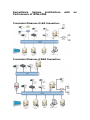
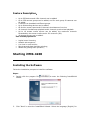
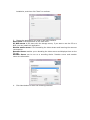
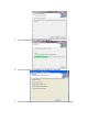
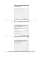
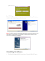
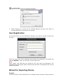
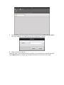
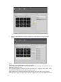
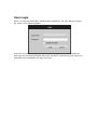
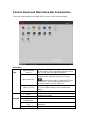
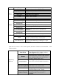
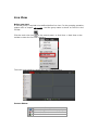
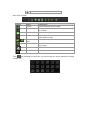
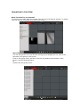
Quick Operation Guide of iVMS-4200 V1.02 2012-02-22 Description iVMS-4200 is a video management software using a distributed structure to manage all the connectable devices. It can manage the NVR, DVR, IP cameras, compression card and decoders. With different management and configuration modules and a reasonable collocation, it provides many solutions for different surveillance scenario, medium or small scale. It is a steady and reliable system with functions like realtime monitoring, video recording and searching, file backup, TV wall displaying, etc. This user manual describes the function, configuration and operation steps of iVMS4200 software. To ensure the properness and stability of the software, please refer to the contents below and read the manual carefully before installation and operation. This user manual can be acquired from your supplier. Running Environment Operating system: Microsoft Windows 7/Windows 2008(32/64 bit operating system),Windows 2003/2000/Windows XP(32 bit operating system) CPU:Intel Pentium IV 3.0 GHz or above Memory:1G or above Display: 1024*768 or above Note: To simultaneously live view for many channels, or for the channel with high resolution, the higher hardware configuration is needed. The software does not support 64 bit operating system; the above mentioned 64 bit operating system refers to the system which supports 32 bit operating system as well. Surveillance System Architecture Performance of iVMS-4200 Topological Diagram of LAN Connection: Topological Diagram of WAN Connection: with an Feature Description: Up to 256 devices and 1024 channels can be added. Up to 256 camera groups can be added, and for each group 64 cameras can be added. A camera can be added to different groups. Up to 64 decoding devices can be added. 64 division screen layout and 64 channels simultaneous live view. 16 channels simultaneous playback and 4 channels synchronized playback. Up to 16 stream media servers can be added, the maximum channels forwarded by the stream media can be 200 channels (2M). 16 storage servers can be added. User Friendly Operation: Logical menu hierarchy; Movable tab sequence; Live view in multi-screen; Easy drag and draw channels selecting; Wizard for guiding basic operation; Starting iVMS-4200 Installing the Software Follow the installation prompts to install the software. Steps: 1. Double click the program file Wizard. to enter the following InstallShield 2. Click “Next” to start the InstallShield Wizard. Select the language (English) for installation, and then click “Next” to continue. 3. Choose the application you need in the next interface. User Client is the application of the iVMS-4200. PC NVR server is the same with the storage server; if you want to use the PC as a NVR, you can install this application. Stream media server is for forwarding the video stream and lowering the resource consumption. Decoder Server enables you to decoding the video source and displays them on the TV wall. Encoder Server can be run as a encoding device. Decoder server and encoder server are alternative. 4. Click Next button to enter the following interface. 5. Click Install button to install the software. 6. You can check the checkboxes to create the shortcut. 7. Click Next button to complete the installation of vcredist_x86 patch. 8. Check the checkbox of the “I have read and accept the license terms.” and click Next button. 9. Click Install button to continue. 10. If needed, the Driver installation requirement pops up to ask you to install or update the driver. Install WinPcap Follow the installation prompt to complete the installation of WinPcap. If it has been installed on your computer, you can cancel this step. Note: The SADP is used for automatically searching the online active devices in the local network. If the WinPcap is not installed, the SADP software cannot be used. Click Finish to complete the installation. Uninstalling the Software 1. Click StartAll Programs4200 client and select “Uninstall iVMS-4200” option. to enter the following interface: 2. Select “Remove” to remove all the installed features and then click “Next” to uninstall iVMS-4200 according to the prompt. User Registration For the first time to use the iVMS-4200 software, you need to register a super user for login. Enter the super user name, password and confirm the password in the dialog box and click Register. Then, you can log in as the super user. Note: Enter, Space, and TAB keys are invalid for the user name and password. The password cannot be empty, and it should not be less than six characters and can’t be copied and pasted. Wizard for Importing Device Purpose: The main function of the iVMS-4200 is to manage devices remotely. Thus the task on the top hierarchy is to add the device to the management list. All the devices managed by the iVMS-4200 must be connected to the IP network. For the first time user, the wizard message box pops up to ask you whether you want to be guided for the basic operation of the client software. If this is not the first time you use the client software, the wizard doesn’t pop up, and you can also use the wizard, click Help and Open Wizard. Click Entering Guide to start the wizard, or click Cancel to exit the wizard. Steps: 1. According to the hint, click Add icon to add devices to the management list of the software. 2. 3. Create a nickname for the device, enter the IP address and the port number of the remote device, enter the user name, and the password of the device. Click Add icon to add the device. If you add the device with a domain name, you can check the Private Domain Mode checkbox. And create a nickname, enter the domain name and port number, and enter the admin name and password of the device to add the device. You can also click Show online device to show the device connected to the same Local Area Network. Steps: 1) Select the device in the device list, and the information of the device such as the MAC address the software version and the serial number is shown in the left part. The information in this part can’t be modified. 2) In the Network information area, you can modify the IP address the Subnet Mask and the Port number with entering the admin password of the device. 3) You can also recover the default password for the device, with the code provided by the authorized engineers. 4. Camera Group Adding When adding a device, you can check the Export to group checkbox to export the device you added to certain management group. By default, the name of the group is the same with the name of the device you just added. If you don’t want to add the group in this way due to the default name issue. You can click Next page, to enter the adding group interface. Click Save to add a new user. Click Modify to change the settings for the new user. 5. Click the Add on Group dialog box. Edit the name of group and then click OK to save your settings. The added group will be displayed in the list. 6. Import Channels to Group In the left area on the Camera Import interface, click to select the channels and then click Import button to import the selected channels to the Group on the right. 7. You can drag and select multiple channels to import them to the group you added. Note: The devices to be added must be online currently. Each channel can be added to one group only once, while the one channel can be added to different groups. Up to 256 groups can be added, and 64 channels can be added to each group, with a maximum of 1024 channels for all the groups totally. After importing the selected channels to the group, you can return to the control panel and then enter the Main View interface to get a live view of the added channels. User Login When you open the iVMS-4200 software after registration, the login dialog box pops up, shown in the following figure: Input the user name and password, and then click Login. You can also enable the auto-login by checking the Enable Auto-login checkbox,and then the user name and password is not needed for the login next time. Control Panel and Main Menu Bar Introduction The main control panel of the iVMS-4200 is shown in the following figure: Menu Bar: File Open Captured Picture: Open Video File: Open Log File: Exit: Lock: System Switch User: System Configuration: Import Configuration File: Export Configuration Enter the setting interface to browse the folder in the host PC of the exported captured picture file (s) and view the captured pictures. Open the video player and browse the folder location of the exported video file (s), click to browse the folder in the host PC of the record files. You can also capture pictures during the playing of the video file. Enter the Log File interface to browse in the host PC of the folder location of the exported log file(s). Exit the iVMS-4200 remote client. Lock the screen operation. You must log in after locking the system. Switch login user. Enter the System Configuration interface. Import client configuration file from your computer. Export client configuration file to your computer. View Tools Help File: 1024*768: 1280*1024: Full Screen: Control Panel: Main View: E-map: Event Search: TV Wall: Import Camera Camera Settings Account Management Device Management Storage Server Management Stream Media Server Management Decoding Device Management Broadcast Open Wizard About User Manual (F1) Display window at size of 1024*768. Display window at size of 1280*1024. Display window in full screen. Enter Control Panel. Enter Main View interface. Enter E-map interface. Enter Event Search interface. Enter TV Wall Setting interface. Enter Import Camera interface. Enter Camera Setting interface. Enter User Account Management interface. Enter Device Management interface. Enter Storage Server Management interface. Enter Stream Media Server Management interface. Enter Decoding Device Management interface. Select device to start broadcasting. Use the guide for camera import. View information of the client software, including company, software name, version, etc. Click to open the User Manual; you can also open the User Manual by pressing FI on your keyboard. There are 14 icons on the control panel, and their functions are described in the following table: Main View E-map Operating Options Event Search Remote Playback TV Wall Import Camera Viewing live and playback video; realize video operation (e.g., picture capture, recording, PTZ control, etc.). Managing and displaying E-Map and hot areas and spots; realize E-Map operation (e.g., operate map zoom in/out, view hot spot, display alarm, etc.) Searching and playback of the event record files; realize playback operation. Playback the recorded video and/or audio files in the remote client. Configuring the decoding of the channels and show them on the TV wall. Adding, modifying or removing the camera groups; import/export of cameras. Local Log Search Account Management Device Management Management Options Storage Server Management Stream Media Server Decoding Device TV Wall Management Configuration Options Camera Settings System Configuration Searching, viewing and backup of local logs (alarm, operation, system logs). Adding, modifying or removing the user account parameters; assign operating permission to each user. Adding, modifying or removing the DVR device; configuring parameters (e.g., network, alarm input/output, HDD, etc.) for the added DVR. Adding, modifying or removing the storage server; configuring parameters (e.g., record schedule, network, HDD, etc.) for the added storage server. Adding, modifying or removing the stream media server; configuring parameters (e.g., RTSP port, upper/lower limit, etc.) for the added stream media server. Adding, modifying or removing the decoder; configuring parameters (e.g., network, alarm input/output, exception, etc.) for the added decoder. Adding, modifying and deleting the TV wall. Configuring camera parameters (e.g., image quality, record schedule, motion detection, etc.). Configuring the general parameters (e.g., saving path of files, alarm sound, Email, etc.). Live View Before you start: A camera group is required to be defined before live view. For the grouping operation, please refer to chapter 错误!未找到引用源。. And the group name is shown on the list in the left bar. Click the main view icon on the control panel, or click View -> Main View on the toolbar to enter the live view interface. The main view interface is shown as in the following figure: Camera Status: Icon Description Camera is online and works properly. Camera is offline. Camera is in live view. Camera is in recording status. Main View Toolbar: Button Name Layout Description Select different layout mode. Full Screen Display video in full screen mode, click again to restore. Stop the display of all the cameras. Stop All Manual Record Previous and Next Auto Switch Start manual record for the selected channel, click again to stop. Click to view previous and next camera. Volume Start auto switching the screen by cameras or by groups. Adjust the volume for live audio. Live Audio Enable/disable live audio. Click the following box pops up, you can choose the screen layout by clicking certain icon. Operations in Live View Start live view for one channel: To view the live video, drag the camera from the list to the display window, or double click the camera name after you select one screen. Start live view for camera group: You can also get the live view for the whole group to display the live view of the cameras in the group in the screen. Click on the group name, and then click the Play button at the bottom of the screen, see the following figure. Or Double click the group name. Toolbar in each display window: Button Description Capture Start manual record, click it again to stop Start voice talk, click again to stop. This two-way audio can be used for only one camera at one time. When you enable the voice talk of one camera, then the voice talk for other camera is stopped. PTZ control, 8 direction icons will be displayed on the video. Check the camera status Go to the camera setting interface Stop live view Remote playback about 7 minutes record of current camera Audio button, click to open and close Stop live view: To stop the live view for one channel, you can click To stop the live view for all the channels, click in the quick setting toolbar. on the bottom bar. Cycle Live View: Cycle live view mode includes the auto-switch in one screen or the auto-switch in multi-screen. 1. Click the next to the . 2. Choose the auto-switch mode and set the interval for the switching. 3. Click on the toolbar on the bottom to start the cycle live view. Capture in Live View Steps: 1. Select the screen. 2. Click icon on the bottom toolbar of Main View, or click bar of this display window. icon in the tool A small window of the captured picture will be displayed to notify you whether the capture is done or not. If the capture is successful, there will be a link to the saving path of the pictures, and if not, there will be error messages accordingly. To view the captured pictures: Click on the small window of the pictures showed on the right bottom after capture. Click the icon on the left toolbar; all the pictures captured on the remote client are stored here. Click File button on the toolbar and select Open Captured File.