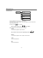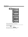
1
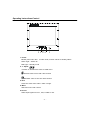
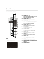
20-INCH
TFT-LCD MONITOR RACK MOUNT
ADMNLCD20RK
INSTRUCTION MANUAL
Please read this manual thoroughly before use, and keep it handy for future reference.
Part Number 8200-0393-00 Rev. A
WARNING:
TO REDUCE THE RISK OF FIRE OR ELECTRIC SHOCK, DO NOT EXPOSE THIS PRODUCT
TO RAIN OR MOISTURE.
DO NOT INSERT ANY METALLIC OBJECT THROUGH VENTILATION GRILLS.
CAUTION:
CAUTION
Explanation of Graphical Symbols
The lightning flash with arrowhead symbol, within an equilateral triangle, is intended
to alert the user to the presence of uninsulated "dangerous voltage" within the
product's enclosure that may be of sufficient magnitude to constitute a risk of electric
shock to persons.
The exclamation point within an equilateral triangle is intended to alert the user to the
presence of important operating and maintenance (servicing) instructions in the
literature accompanying the product.
Precautions
Safety -----------------------------------------
Installation ------------------------------------------
Should any liquid or solid object fall into the
cabinet, unplug the unit and have it checked by
the qualified personnel before operating it any
further.
Do not install the unit in an extremely hot or humid
place or in a place subject to excessive dust or
mechanical vibration.
The unit is not designed to be waterproof.
Exposure to rain or water may damage the unit.
Unplug the unit from the wall outlet if it is not
going to be used for several days or more. To
disconnect the cord, pull it out by the plug. Never
pull the cord itself.
Cleaning -------------------------------------Clean the unit with a slightly damp soft cloth.
Use a mild household detergent. Never use strong
solvents such as thinner or benzine as they might
damage the finish of the unit.
Allow adequate air circulation to prevent internal
heat build-up. Do not place the unit on surfaces
(rugs, blankets, etc.) or near materials(curtains,
draperies) that may block the ventilation holes.
Retain the original carton and packing materials
for safe transport of this unit in the future.
-2 -
FCC COMPLIANCE STATEMENT
INFORMATION TO THE USER: THIS EQUIPMENT HAS BEEN
TESTED AND FOUND TO COMPLY WITH THE LIMITS FOR A CLASS B
DIGITAL DEVICE, PURSUANT TO PART 15 OF THE FCC RULES. THESE
LIMITS ARE DESIGNED TO PROVIDE REASONABLE PROTECTION
AGAINST HARMFUL INTERFERENCE IN A RESIDENTIAL INSTALLATION.
THIS EQUIPMENT GENERATES, USES AND CAN RADIATE RADIO
FREQUENCY ENERGY AND, IF NOT INSTALLED AND USED IN
ACCORDANCE WITH THE INSTRUCTIONS, MAY CAUSE HARMFUL
INTERFERENCE TO RADIO COMMUNICATIONS. HOWEVER, THERE IS
NO GUARANTEE THAT INTERFERENCE WILL NOT OCCUR IN A
PARTICULAR INSTALLATION. IF THIS EQUIPMENT DOES CAUSE
HARMFUL INTERFERENCE TO RADIO OR TELEVISION RECEPTION,
WHICH CAN BE DETERMINED BY TURNING THE EQUIPMENT OFF AND
ON, THE USER IS ENCOURAGED TO TRY TO CORRECT THE
INTERFERENCE BY ONE ON MORE OF THE FOLLOWING MEASURES :
-REORIENT OR RELOCATE THE RECEIVING ANTENNA
-INCREASE THE SEPARATION BETWEEN THE EQUIPMENT AND
RECEIVER.
-CONNECT THE EQUIPMENT INTO AN OUTLET ON A CIRCUIT
DIFFERENT FROM THAT TO WHICH THE RECEIVER IS CONNECTED.
-CONSULT THE DEALER OR AN EXPERIENCED RADIO/TV TECHNICIAN
FOR HELP
CAUTION: CHANGES OR MODIFICATIONS NOT EXPRESSLY
APPROVED BY THE PARTY RESPONSIBLE FOR COMPLIANCE COULD
VOID THE USER'S AUTHORITY TO OPERATE THE EQUIPMENT.
THIS PRODUCT COMPLIES WITH VARIOUS OTHER REGIONAL AND SAFETY
REGULATIONS SUCH AS: FCC, CE.
THESE CERTIFICATIONS ARE NOTED ON THE PRODUCT LABEL.
-3 -
IMPORTANT SAFEGUARDS
1.
READ INSTRUCTIONS -- All the safety and operating
instructions should be read before the appliance is operated.
10
OWER CORDS -- Do not allow anything to rest on the power
cord. Do not locat e video monitor or equipment where the
cord will be abused by persons walking on it.
2.
RETAIN INSTRUCTIONS -- The safety and operating
instructions should be retained for future reference.
11
HEED WARNINGS -- Follow all instructions marked on the
video monitor or equipment.
3.
CLEANING -- Unplug video monitor or equipment from the
wall outlet before cleaning. Do not use liquid cleaners or
aerosol cleaners. Use a damp cloth for cleaning.
12
LIGHTNING -- For added protection for video monitor or
equipment during a lightning storm, or when it is left
unattended and unused for long periods of time, unplug it
from the wall outlet and disconnect the antenna or cable
system. This will prevent damage to the video product due to
lightning and power-line surges.
4.
ATTACHMENTS -- Do not use attachments not
recommended by the video monitor or equipment
manufacturer as they may result in the risk of fire, electric
shock or injury to persons.
13
5.
WATER AND MOISTURE -- Do not use video monitor or
equipment near water -- for example, near a bathtub,
washbowl, kitchen sink, laundry tub, in a wet basement, or
near a swimming pool, or the like.
OVERLOADING --Do not overload wall outlets and extension
cords as this can result in a risk of fire or electric shock.
14
ACCESSORIES -- Do not place video monitor or equipment
on an unstable cart, stand or table. The video monitor or
equipment may fall, causing serious injury to a child or adult,
and serious damage to the equipment. Wall or shelf mounting
should follow the manufacturer's instructions, and should use
a mounting kit approved by the manufacturer.
OBJECT AND LIQUID ENTRY -- Never push objects of any
kind into video monitor or equipment through openings as
they may touch dangerous voltage points or short-out parts
that could result in a fire or electric shock. Never spill liquid of
any kind on the product.
15
SERVICING -- Do not attempt to service video monitor or
equipment yourself as opening or removing covers may
expose you to dangerous voltage or other hazards. Refer all
servicing to qualified service personnel.
16
DAMAGE REQUIRING SERVICE -- Unplug video monitor or
equipment from the wall outlet and refer servicing to qualified
service personnel under the following conditions:
A.
When the power-supply cord or the plug has been
damaged.
B.
If liquid has spilled, or objects have fallen into the
video product.
C.
If the video product has been exposed to rain or
water.
D.
If the video product does not operate normally by
following the operating instructions, adjust only those
controls that are covered by the operating instructions
as an improper adjustment of other controls may
result in damage and will often require extensive work
by a qualified technician to restore the video product
to its normal operation.
E.
If the video product has been dropped, or the cabinet
damaged.
F.
When the video product exhibits a distinct change in
performance -- this indicates a need for service.
6.
6A.
Video monitor or equipment and cart combinations should be
moved with care. Quick stops, excessive force, and uneven
surfaces may cause the equipment and cart combination to
overturn.
7.
VENTILATION -- Slots and openings in the cabinet and the
back or bottom are provided for ventilation, and to ensure
reliable operation of the video monitor or equipment and to
protect it from overheating. These openings must not be
blocked or covered. The openings should never be blocked
by placing the video monitor or equipment on a bed, sofa,
rug, or other similar surface. Video monitor or equipment
should never be placed near or over a radiator or heat
register. Video monitor or equipment receiver should not be
placed in a built-in installation such as a bookcase unless
proper ventilation is provided.
8.
POWER SOURCES -- Video monitor or equipment should be
operated only from the type of power source indicated on the
marking label. If you are not sure of the type of power
supplied to your home, consult your video monitor or
equipment dealer or local power company. For video monitor
or equipment designed to operate from battery power refer to
the operating instructions.
9.
GROUNDING OR POLARIZATION -- This video monitor may
be equipped with a polarized alternating - current line plug (a
plug having one blade wider than the other). This plug will fit
into the power outlet only one way. This is a saf ety feature. If
you are unable to insert the plug fully into the outlet, try
reversing the plug. If the plug should still fail to fit, contact
your electrician to replace your obsolete outlet. Do not defeat
the safety purpose of the polarized plug.
117. REPLACEMENT PARTS -- When replacement parts are
required, be sure the service technician has us ed replacement
parts specified by the manufacturer or that have the same
characteristics as the original part. Unauthorized substitutions
may result in fire, electric shock or other hazards.
118.
19.
Alternate Warnings - This video monitor is equipped with a
three-wire grounding-type plug, a plug having a third
(grounding) pin. This plug will only fit into a grounding-type
power outlet. This is a safety feature. If you are unable to
insert the plug into the outlet, contact your electrician to
replace your obsolete outlet. Do not defeat the safety
purpose of the grounding-type plug.
-4 -
SAFETY CHECK -- Upon completion of any service or repairs
to this video product, ask the service technician to perform
safety checks to determine that the video product is in proper
operating condition.
FIELD INSTALLATION -- This installation should be made by
a qualified service person and should conform to all local
codes.
TABLE OF CONTENTS
l
Warning… … … … … ..… … … … … … … … … … … … … … … … … … … … … … … … … …
2
l
FCC Compliance Statement… … … … … … … … … … … … … … … … … … … … … … ..
3
l
Important Safeguards… … … … … … … … … … … … … … … … … … … … … … … … … .. 4
l
Table Of Contents… … … … … … … … … … … … … … … … … … … … … … … … … … … . 5
l
Features… … … .… … … … … … … … … … … … … … … … … ..… … … … … … … … … … .. 6
l
Operating Instructions-Controls… … … … … … … … … … … … … … … … … … … … … .. 7
l
Backside Connections… … … … … … … … … … … … … … … … … … … … … … … … … .. 8
l
Remote Control… … … … … … … … … … … … … … … … … … … … … … … … … … … … . 9
l
OSD Architecture… … … … … … … … … … … … … … … … … … … … … … … … … … …
12
A. Audio Function… … … … … … … … … … … … … … … … … … … … … … … … … … .. 12
B. Video Function… … … … … … … … … … … … … … … … … … … … … … … … … … .. 13
C. Image Function… … … … … … … … … … … … … … … … … … … … … … … … … … . 16
l
LCD Monitor Mounting guide..… … … .… … … … … … … … … … … … … … … … … … …
19
A. Rack Mount… … … … … … … … … … … … … … … … … … … … … … … … … … … … .. 19
l
Connecting Device… … … … … … … … … … … … … … … … … … … … … … … … … … …
l
Specification… … … … … … … … … … … … … … … … … … … … … … … … … … … … … … 21
l
Appendixes … … … … … … … … … … … … … … … … … … … … … … … … … … … … … … 22
l
Memo… … … … … … … … … … … … … … … … … … … … … … … … … … … … … … … … .. 23
-5 -
20
Features
l
20-inch LCD monitor with multiple inputs (Composite video, Y/C (SVHS) and
D-sub computer)
l
High brightness of 500 cd/
l
High contrast of 480 :1
l
Wide viewing angle of 160 degrees, both vertically and horizontally
l
Fast LCD response time of 16ms, allowing excellent rendering of motion
l
Latching power supply automatically restores power after interruption or remote
switching
l
Built-in power transformer with standard AC cord
l
Remote control for ADMNLCD20RK, adding flexibility and easy control
l
Simple OSD Menu User Interface
l
European and North American power cords for easy installation
l
Video input supports both NTSC / PAL / SECAM standards
l
User selectable 6500K / 9300K color temperature settings
l
Auto termination (75 Ohms)
l
Standard AC power supply ranges from 100V ~ 240V
-6 -
Operating Instructions-Control
6 5 43 2
1
1. Power
Monitor power ON / OFF. At OFF mode, monitor will be at standby status.
Green Light – Power On
Red Light – Standby mode
2. 3. Adjust
Increase or decrease the value on OSD menu.
Increase value or turn ON / OFF function
Decrease value or turn ON / OFF function
4. Item
Chose sub menu from Audio / Video / Image.
5. Menu
OSD menu ON / OFF control.
6. Source
Select input signal from AV1, AV2, S-Video or PC.
-7 -
Backside Connections
A. BACK PANEL CONTROL
1, 2 AUDIO 2 IN (L, R)
Stereo Audio Signal Input, this input is for
AV2 or PC (refer to Note below)
3, 4 AUDIO 2 OUT (L, R)
Audio looping outputs for AUDIO 2
5, 6 AUDIO 1 IN (L, R)
Stereo Audio Signal Input, this input is for
AV1 or Y/C (refer to Note below)
7, 8 AUDIO 1 OUT (L, R)
Audio looping outputs for AUDIO 1
9
Y/C IN (SVHS)
Y/C separated signal input
16
10
Y/C OUT (SVHS)
Y/C separated signal looping output
17
11
VIDEO 2 OUT
Video looping output for VIDEO 2
18
12
VIDEO 2 IN
Composite signal Input for VIDEO 2
13
VIDEO 1 OUT
Video looping output for VIDEO 1
14
NOTE :
VIDEO 1 IN
Composite signal Input for VIDEO 1
Audio Connections
15
REGULATED DC12V POWER OUTPUT
(500mA)
Audio 1
PC
AV 1
16
AUDIO LIVE OUT
V
17
18.
PC VGA IN
AC POWER CORD
V
AV 2
S-Video
Audio 2
V
V
-8 -
Remote Control
Key Function
Power
Turn ON / OFF monitor. At OFF mode monitor will
be standby status.
Scan
Scan
Set
Sel.
1
2
3
4
5
6
7
8
9
Power
TV
PC
AV1
+100
AV2
Inactive for rack mount model
Set (Restricted Channel Setting)
Inactive for rack mount model
Sel. (Restricted Channel Setting)
Inactive for rack mount model
0
TV
-
TV
PC
Inactive for rack mount model
PC
Select PC monitor mode.
AV1
AV1
Select display to Video1.
AV2
AV2
Select display to Video2.
S-Video
Select display to S-Video
Note: All TV/CATV functions are inactive for rack mount model
-9 -
Remote Control
Jump
Return to previous channel.
Memory
Inactive for rack mount model
Select
Inactive for rack mount model
Menu
OSD menu ON / OFF and selection.
Item
Chose sub menu from Audio / Video / Image list.
+/Increase or decrease the value on OSD menu.
+ Increase value or turn ON / OFF function
- Decrease value or turn ON / OFF function
MTS :
Inactive for rack mount model
Air/CATV
Inactive for rack mount model
Mute
The button controls audio volume to mute.
Display
Displays video source title.
- 10 -
+
Volume
Used adjust +/- to increase / decrease volume..
+ Increase volume value
- Decrease volume value
Channel
Inactive for rack mount model
- 11 -
OSD Architecture
A. Audio Function
Audio
Volume
Balance
Treble
Bass
Press the MENU button will bring up the OSD Menu.
Press MENU again to select AUDIO. Then, press ITEM to choose functions that
require proper adjustments.
As shown, press
key to adjust.
-
+
Note: In remote control, press
key to adjust.
(After adjustment, the monitor will store new settings)
Volume
Controls built-in speakers’ output volumes.
Note: Volume control can also be adjusted by hot key.
Balance
Controls built-in speakers’ LEFT / RIGHT volume balance.
Treble
Audio treble adjustment.
Bass
Audio bass adjustment.
- 12 -
+
OSD Architecture
B. Video Function
Video
Contrast
Brightness
Backlight
Color
Tint
Color Temperature
Sharpness
CCD Mode
Display On/Off
Recall
Under AV1, AV2, S-Video mode:
Press the MENU button will bring up the OSD Menu.
Press MENU again to select VIDEO. Then, press ITEM to choose functions that
require proper adjustments.
As shown, press
key to adjust.
Note: In remote control, press
+
key to adjust.
(After adjustment, the monitor will store new settings)
- 13 -
OSD Architecture
Contrast
Permits adjustment of contrast between light and dark areas of the picture.
Example:
Setting
Slide bar
Brightness
Adjusts the overall picture shade and brightness.
Tip: Use the Brightness to make details in the dark areas of the
picture to be just visible, and Contrast to “brighten” the picture
without causing noises and foreheads to turn white.
Back Light
Adjusts panel backlight luminance.
Color
Adds coloring to the black and white picture content (of a color signal), and
is usually set for viewer’s preference in color saturation.
TINT
Adjusts all the colors on the screen, but is most noticeable to the eye in
reds and yellows, and is also usually set for pleasing face tones.
Note: Appears in NTSC mode only.
Sharpness
Sets the desired sharpening enhancement to the picture.
Color Temperature
Selects color temperature of either 6500K
- 14 -
OSD Architecture
CCD Mode
If video signal source directly comes from CCD camera, using CCD Mode
is suggested to obtain better picture performance.
Display
Displays video source title.
RECALL
Sets monitor to the original factory setting.
- 15 -
OSD Architecture
C. Image Function
Image
Auto
Contrast
Brightness
Backlight
H-Position
V-Position
Clock
Phase
DOS Mode
Color Temperature
White Balance
Display
Under Image mode:
Press the MENU button will bring up the OSD Menu.
Press MENU again to select IMAGE. Then, press ITEM to choose functions that
require proper adjustments.
As shown, press
key to adjust.
Note: In remote control, press
+
key to adjust.
(After adjustment, the monitor will store new settings)
- 16 -
OSD Architecture
Auto
Auto detect screen detail data such as clock and phase.
Contrast
Permits adjustment for contrast between light or dark areas of the picture.
Brightness
Adjusts the overall picture shade and brightness.
Tip: Use the Brightness to make details in the dark areas of the picture to
be just visible, and Contrast to “brighten” the picture without causing
noises and foreheads to turn white.
Back Light
Allows to adjust panel backlight luminance.
H-position
Allows adjustment for horizontal position.
V-position
Allows adjustment for vertical position.
Clock
Is used to adjust best picture quality. It adjusts the numbers of the pixel clock
across one line time. Therefore it can affect the picture position and size.
Note: improper adjustment will caused image failure.
Phase
Is used to adjust best picture quality. It adjusts the sampling phase across one
pixel time. When the phase is not adjusted properly, the picture will be unclear.
Therefore this value should be carefully adjusted.
Note: improper adjustment will cause image failure.
- 17 -
OSD Architecture
Dos Mode
Supports picture enhancement when using under DOS mode.
Color Temperature
Selects 9300K or 6500K color temperature for display.
White Balance
Allows the picture white balance adjustment.
Display
Displays video source title.
Recall
Sets monitor to the original factory setting.
- 18 -
LCD monitor Mounting Guide
A. Rack mount
The ADMLLCD20RK fits into a standard 19-inch rack. Follow the mounting guide to
install the monitor.
450MM
- 19 -
Connecting Device
DVD or other
video source
Camera or other
video source
Loop out to
another
video device
Camera or other
video source
PC
a.
Connect PC to Monitor through VGA connector as shown on the above picture
b.
Connect External device such as DVD or Game Player to Monitor as shown on the
above picture
c.
Connect CCD Camera 1 and 2 to Monitor through Video Input 1 and 2 (BNC Connector)
as showing on the above picture
d.
PC resolution supported
640 x 480 60Hz
800 x 600 56Hz
640 x 480 72Hz
800 x 600 70Hz
640 x 480 75Hz
800 x 600 72Hz
800 x 600 75Hz
Note: Please refer to page 17 for auto detection after changing resolution setting.
- 20 -
Specification
Model
ADMNLCD20RK
LCD Panel
20.1 inch” TFT, TN Mode
Display Mode
3D De-interlace
Input Filter
3D Comb filter
Display area
408 x 306mm
Resolution
800 x 600
Brightness
500 cd/m @6mA
2
Contrast ratio
480:1
Response Time
View angle
L/R
U/D
16ms typ.
80(left),80(right),60(up),60(down)
80(left), 80(right), 80(up),80(down)
Input Signal
CR=10
CR=5
BNCx2 in
BNC x2 out (Auto Termination)
D-Sub 15pin
Y/C x1 in
Y/C x1 out
Audio In/Out
RCA(R/L) x 2 set in
RCA(R/L) x 2 set out
Operating Controls
OSD
Power Supply
AC 96~256V 50/60Hz
Power Consumption
52W
Dimension
420x406.5x85.2mm
Weight
6.8kg
Temperature
10~60 degrees C
Humidity
20%~80%
- 21 -
Appendixes
A. TROUBLE SHOOTING
Problem:
1.No power
2.No video or audio
3.Bad video or audio
4.Image not stable
5.Ab-normal line
6.Ghost image
7.Desired video disappears
Checking:
Power-cord connecting Power-on?
Change to right input channel?
Check signal cable?
Any interrupt from other devices?
Adjust video control on OSD?
Adjust video source?
B
Package List
A. ADMNLCD20RK
20” LCD Monitor
x1
B. American Power Cord
x1
C. Europe Power Cord
x1
D. User Manual
x1
E. Accessory Kit
x1
- 22 -
Memo
- 23 -
Please visit our website for more information
www.americandynamics.net
©2003 Sensormatic Electronics Corporation.
Product specifications subject to change without notice.
Certain product names mentioned herein may be trade names
and/or registered trademarks of other companies.