1
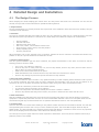
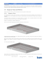
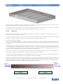
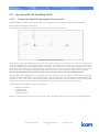
Revision 1.0
ICAM limited,
Spring Gardens
London Road,
Washington,
West Sussex
BN20 3BS UK
Tel: +44 (0) 1903 892222
Fax: +44 (0) 1903 892277
e-mail address: [email protected]
Website: www.firetracer.com
COPYRIGHT INFORMATION
ICAM Ltd Copyright 2004
This document may not be reproduced, in whole or in
part, by any means without the prior permission of the
copyright owner.
Part No. 09-0003-10b
PipeTracer User Manual
1
Copyright C 2004
Contents
1
2
INTRODUCTION ..................................................................................................................... 3
AIR-SAMPLING ....................................................................................................................... 4
2.1
Uses of Air-sampling ................................................................................................................. 4
2.1.1
2.1.2
2.1.3
2.1.4
2.1.5
2.1.6
3
GENERAL DESIGN................................................................................................................... 6
3.1
3.2
3.3
3.4
Layouts with Air Handling Units (AHUs) ...................................................................................... 6
Still Air Environments (without AHUs) ......................................................................................... 6
Unusual Applications ................................................................................................................. 7
Wide-bore Systems ................................................................................................................... 7
3.5
3.6
PipeTracer Software.................................................................................................................. 11
Micro-bore Systems................................................................................................................... 12
4.1
4.2
The Design Process................................................................................................................... 13
Response Times and Dilution ..................................................................................................... 14
4.3
Layouts with Air Handling Units.................................................................................................. 16
4.4
Design for Still Air Environments ................................................................................................ 23
4.5
Unusual Applications ................................................................................................................. 27
3.4.1
3.4.2
3.4.3
3.4.4
4
Very Early Detection ................................................................................................................................ 4
Central Service ........................................................................................................................................ 4
Protection of Voids, Inaccessible and High Areas ....................................................................................... 4
Combined Fire & Gas Detection with options ............................................................................................. 4
Flexibility................................................................................................................................................. 5
Invisible installations................................................................................................................................ 5
Main Units ............................................................................................................................................... 7
Pipe Sections and Fittings......................................................................................................................... 8
Brackets................................................................................................................................................ 10
Sintered Filter........................................................................................................................................ 10
Detailed Design and Installation ............................................................................................ 13
4.2.1
4.2.2
4.3.1
4.3.2
4.3.3
4.3.4
4.3.5
4.3.6
4.3.7
4.3.8
4.4.1
4.4.2
4.4.3
4.5.1
4.5.2
4.5.3
4.5.4
4.5.5
4.5.6
Response Times .................................................................................................................................... 14
Dilution ................................................................................................................................................. 15
Design for Rapid Air Movement Environments ......................................................................................... 16
Simple Re-circulation Units ..................................................................................................................... 17
AHUs with Low Level Return................................................................................................................... 18
AHUs with High Level Return.................................................................................................................. 18
AHUs with Under Floor Return ................................................................................................................ 19
Design for Duct Sampling Systems.......................................................................................................... 20
Condensation Trap................................................................................................................................. 21
Sub-floors and ceiling voids .................................................................................................................... 22
General Still Air Design........................................................................................................................... 23
Capillary Sampling ................................................................................................................................. 25
Localised Monitoring .............................................................................................................................. 26
High Areas ............................................................................................................................................ 27
Clean Rooms ......................................................................................................................................... 28
Cold Stores............................................................................................................................................ 29
Supermarkets ........................................................................................................................................ 30
Warehouses .......................................................................................................................................... 30
Server Rooms ........................................................................................................................................ 31
Part No. 09-0003-10b
PipeTracer User Manual
2
Copyright C 2004
1 INTRODUCTION
This document is a guide for the installation of pipe-work for air-sampling systems. The pipe network is just as important as
the detector itself and provides a means of obtaining a reliable and continuous sample of air to be monitored.
The pipework for air-sampling systems can vary greatly depending on the particular application. This manual, therefore,
gives overall guidelines that can be applied to any system but also a number of specialised set-ups are described in more
detail. These include:
•
•
•
•
•
Clean rooms
Cold stores
Duct sampling
High or large area buildings
Computer Centres
This guide is intended to give general guidelines for installing air-sampling systems but in each case, the local standards and
codes of practice should be taken into account. Guidance on the design of systems is given in BS 5839, BS 6266 and/or
BFPSA Code of Practice for Category 1 Aspirating Detection Systems.
It is strongly recommended that, before designing the pipe-work system, smoke tests be undertaken in order to show the
patterns of air movement within the areas to be protected. This is particularly important in rooms with air-handling
equipment. More details are given at relevant points throughout the text.
Part No. 09-0003-10b
PipeTracer User Manual
3
Copyright C 2004
2 AIR-SAMPLING
ICAM manufactures air-sampling systems with a conventional wide bore and also a unique micro-bore pipe-work. Both types
of system are suitable for monitoring sensitive installations such as clean rooms, computer centres, telecommunications
rooms and other areas.
Air sampling is the technique where air is drawn through pipes from protected areas to a central unit, where the actual
smoke/gas detector is situated. This is in contrast with point detectors, where the unit is actually in the protected area.
The sampled air is monitored by sophisticated analysers for very low levels of smoke. This enables very early warning to be
given well before the first flame is visible.
2.1 Uses of Air-sampling
Air sampling offers many benefits:
•
•
•
•
•
•
2.1.1
Very early detection due to high sensitivity.
Central service using pipe network.
Protection of voids, inaccessible, high areas.
Combined fire and gas detection as well as many other options such as humidity, flood warning, and
temperature.
Good flexibility due to being microprocessor controlled.
Invisible installations using micro-bore pipes or capillary tube sampling within ceilings or below floors.
Very Early Detection
Fires rarely break out in an instantaneous conflagration. Instead, the fire source may smoulder for hours or days before the
flames appear. In this incipient or pre-fire stage, combustion products (mainly smoke) are generated but at levels which
conventional point systems simply cannot spot.
One example is an over-heating resistor. The failure of a component costing very little may cause equipment loss and
severe damage. The key requirement is to detect the pre-fire indications while there is still time to correct the
problem.
Air sampling systems employ a much more sensitive detector than point systems (point systems detect at 1.0%
Obscuration/meter and higher). These sophisticated devices can pick up the traces of incipient fires (between 0.01% and
0.1% Obscuration/meter) and raise an alarm. The incident can then be dealt with well before it becomes an actual fire.
2.1.2
Central Service
In ICAM FireTracers, only the central unit (placed at a convenient location) requires servicing. The alternative is servicing
tens of point detectors, maybe located in many different rooms. This system of using a pipe network with sampling points
means that, with the FT4 for instance, 2000 m2 can be covered with just one detector. Alternatively, with an FT15, fifteen
different server cabinets could be monitored individually. Therefore, if a fault or alarm is sounded, the person responsible
can immediately pinpoint where the problem is without having to look at many detectors individually.
2.1.3
Protection of Voids, Inaccessible and High Areas
Air samplers are ideal for such situations. Sampling points are installed once and then require no further service. By
contrast, point detectors [being located in the actual area], may be difficult or even impossible to test, service or update
because of the location.
2.1.4
Combined Fire & Gas Detection with options
ICAM units feature the patented Gaswitch. This prevents sample ‘contamination’ between pipes. Multiple detectors for
different gases can also be placed in the unit using the same pipe-network, valve, pump etc. High quality sensors can then
be used. By contrast, gas point detectors are expensive, limited in gas type, and require another installation for each new
gas. As well as having an option of gas detection, environmental monitoring is also available. This means that parameters
such as temperature, humidity, flood warnings and security controls can all be monitored with a single e-series product.
Part No. 09-0003-10b
PipeTracer User Manual
4
Copyright C 2004
2.1.5
Flexibility
ICAM units are microprocessor controlled. The control systems are therefore programmable from the unit front panels.
Alarm levels & sensitivities can be set individually for each pipe. These can also have separate values for day and night
along with user configurable alarm delays.
There is also an option to change the display language as well as use a remote panel which can be situated away from the
detector or use the fully integrated software to configure and monitor the system from a PC.
2.1.6
Invisible installations
Often, in situations such as historical buildings, it is important to keep the installation from interfering with the décor or
structure. The FT15 uses micro-bore pipes which are, not only small in diameter, but are also extremely flexible. This
enables pipe runs to be hidden in coving or a similarly unobtrusive place.
When using large-bore pipes, capillary tubes can be used for hiding sampling points. The majority of the pipes are above
the ceiling or beneath the floor and only the end of the capillary tube is visible.
Part No. 09-0003-10b
PipeTracer User Manual
5
Copyright C 2004
3 GENERAL DESIGN
The majority of aspirated smoke detection systems are used in one of two ways. The first is when there is an air handling
system in the area to be protected. The second is when sampling points are used where one would normally use standard
detectors, mainly in still air environments. There are also specific layouts and applications, some of which will be covered
later although it is always necessary to look closely at any installation because almost every location is different.
A classic system layout is shown below. This is the most basic of wide-bore set-ups.
Wall brackets
Pipe with
sampling
holes
End cap
with hole
FireTracer
Pico
3.1 Layouts with Air Handling Units (AHUs)
In any area where AHUs are used, computer rooms for instance, it can normally be assumed that all the air is regularly
cycled through the units or ducts. This means that the sampling points need to be located at or within these ducts in order
to gain the most effective protection.
It is vital that, if it is necessary, an AHU should be operating at all times when being used with an aspirated smoke detection
system. If this is not the case then the system will become ineffective due to the lack of air circulation. If this is unavoidable
then a more complicated system incorporating both duct sampling and general sample points can be implemented.
In all cases the aim must be to place the sampling pipes at the position the smoke is most likely to reach.
This should be established by performing extensive smoke tests, making sure the smoke is clearly visible.
3.2 Still Air Environments (without AHUs)
Still air environments, such as warehouses or store rooms, do not have a pattern for the air movement. This means that the
sampling points must give general cover across the whole expanse of the area. Each system can cover a total area of
2000m2 but careful consideration must be given to the layout in order to design a balanced network that will perform as
required.
Failure to design and install a properly thought out pipe network can result in slow response times thereby negating some of
the early warning ability of the system. The way to avoid any problems occurring is to ensure that all pipes are a similar, or
preferably equal, length.
Part No. 09-0003-10b
PipeTracer User Manual
6
Copyright C 2004
3.3 Unusual Applications
Due to the fact that most installations take place in different environments, the guidelines above are fairly flexible. The
exceptions come when exceptional environments are involved. If the area is essentially a room, with or without AHUs, then
the rules are straightforward and vary little from place to place. Unusual applications are those which deviate in some way
that changes the way the air movements may behave. These include high areas, voids, restricted areas or those which have
safety considerations and places where samples may be contaminated with dust.
In these different and variable situations, it is vital to perform smoke tests to establish the air movements.
3.4 Wide-bore Systems
Conventional air-sampling systems have one to six wide-bore rigid pipes. It is recommended that ABS pipe is used due to its
strength and heat resistant properties. These pipes are usually hung under the ceiling of the area to be protected. Air is
drawn in from the protected area, through a number of small holes in the sidewall of the pipe.
Example of an ABS wide-bore pipe
with sampling holes
The ICAM FireTracer 1 and Pico are good examples of such a system. When smoke enters the central detector, an alarm is
raised, but the unit cannot determine through which pipe the smoke has come.
The ICAM FireTracers 4 & 6 have four and six pipes respectively. When smoke is detected, these units scan through each
pipe individually and can therefore provide a much clearer indication of the smoke source. Micro-bore systems also have this
facility.
NOTE: Pipes should be glued together to avoid separation or leaks but the pipes must not be glued into the
unit itself. Removable unions should be used where maintenance may require pipes to be taken apart or
removed.
3.4.1
•
Main Units
Pico
One pipe running vertically and/or horizontally
Part No. 09-0003-10b
PipeTracer User Manual
7
Copyright C 2004
•
FireTracer
FireTracer 1 has 4 vertical pipes, FireTracer 4 and 6 have horizontal pipe entries.
3.4.2
Pipe Sections and Fittings
•
Straight pipe sections
•
Sockets
•
Unions
Part No. 09-0003-10b
PipeTracer User Manual
8
Copyright C 2004
•
Holes, (typically 3mm diameter)
•
End caps, (typically with a 6mm hole)
•
Bends (45º and 90º), these slow bends minimise pressure loss in the system
NOTE: After the wide bore pipe network has been installed, before the end cap is put on and before the pipes
are attached to the unit, each pipe run should be cleaned using compressed gas or a vacuum cleaner on the
end of the pipe.
•
Capillary tubes
Part No. 09-0003-10b
PipeTracer User Manual
9
Copyright C 2004
3.4.3
Brackets
•
Channel Bracket
•
Studding Bracket
•
Wall Bracket
3.4.4
•
Sintered Filter
End of line sintered filter for micro-bore systems
Part No. 09-0003-10b
PipeTracer User Manual
10
Copyright C 2004
3.5 PipeTracer Software
PipeTracer is ICAM’s pipework modelling and flow calculation software for wide-bore systems.
Once you have modelled your pipe network PipeTracer can predict such quantities as:
•
•
•
Flow times [response]
Flow volumes
Pressure drops
This package has been designed to be simple to use. For example, a set-up wizard simplifies the creation of your pipe
network, while a multi level undo/redo facility is available in the editing stage, should the initial design require altering.
Either metric or imperial units may be selected for editing and display.
A key requirement of such software is the need to calculate air flows through the pipe network. Advanced numerical
optimisation techniques ensure that this process is very fast.
All calculations are based upon full fluid dynamics theory and so take account of laminar and turbulent flow regimes within
the system.
Part No. 09-0003-10b
PipeTracer User Manual
11
Copyright C 2004
3.6 Micro-bore Systems
The ICAM FireTracer 8 and 15 have 8 and 15 micro-bore pipes respectively. The 4mm I.D. pipe is flexible, and therefore
easy to install.
Note: It is vital that the pipes are of a similar length. If this is not the case, performance may be severely
affected.
In contrast with the wide-bore systems, air is only drawn in through the end of the pipe. When smoke is detected, the
system will scan the pipes until the source is found.
Such systems are particularly suited to cabinet protection, where a pipe may be placed directly in each cabinet. This offers
pinpoint location, combined with the earliest possible detection.
In this example the flexible pipes are laid in the floor void, and brought up to the top of each cabinet.
Pipes run under floor
The smoke is not diluted by being mixed with the general air in the room, nor is it dependent upon the vagaries of air
currents. Since each cabinet has an individual pipe, if an alarm occurs, the source can be traced to a single cabinet, rather
than the whole room. This minimises time taken to find the source.
It is recommended that a sintered end of line filter be used at the end of every pipe (as shown in section 2.4.4). This will
ensure that the airflow is not impeded by blockages such as insects.
A sampling point like the one below can also be used to provide both a sturdy and safe end point and also an aesthetically
pleasing one. These can be screwed to walls or ceilings and also incorporate filters. The sampling point is shown as actual
size (34mm outer diameter).
Part No. 09-0003-10b
PipeTracer User Manual
12
Copyright C 2004
4 Detailed Design and Installation
4.1 The Design Process
When designing the actual sampling pipe network there are many factors that need to be considered. The site must be
carefully surveyed and as much information as possible should be gathered.
1. Requirements
The first consideration is to precisely ascertain the requirements of the installation. Once these have been decided, the type
of situation can be looked at.
2. Activities
The types of activities that take place within the space are very important. A public area of a particular shape could well
have different system requirements to a warehouse of a similar shape. Some different examples are outlined below.
•
•
•
•
•
•
•
Historic buildings
Chill and Cold stores
Microelectronics clean rooms
EDP rooms, offices, communications switch rooms
Shops, theatres, leisure centres, churches, libraries
Hotels, hospitals, prisons
Factories, warehouses
Other information such as the expected hours of operation, whether the area is manned or unmanned and whether any
pollution or dirty air is present should also be taken into account.
3. Physical Characteristics
Once the general installation type has been considered, the physical characteristics of the space are looked at and the
following questions should be asked.
•
•
•
•
•
Is it a room, void, cabinet or enclosure?
Are there any floor or ceiling voids and, if so, how are they divided, are there any ducts, what are these used for
and are there any services already present?
What are the exact measurements of the space?
What materials have been used and are there any areas where the network has to avoid?
Are there any existing fire protection systems and where are they situated?
4. Environmental Conditions
The environment within the space can have a very significant bearing on which sampling method should be used to protect
it. As already mentioned, the smoke tests are vital in gathering this information. This can tell you the patterns of air
movement, the rate of circulation and whether the airflow is static at any point. Other considerations include:
•
•
•
•
If fresh air is introduced, at what rate and in what quantity?
Is a reference detector necessary due to pollution?
What is the temperature and relative humidity and are these constant or variable?
Are there any activities that may produce smoke, dust, steam or flames and how often does this occur?
5. Risk Assessment
With any installation it is likely that some areas require more protection than others. This could be because of expensive
equipment or a particularly vulnerable area such as a store for flammable materials. These more susceptible areas must be
considered along with any structural hazards such as synthetic materials and foams or soft wood partitioning.
6. Potential Sites
There are also factors to consider when deciding on the position at which the FireTracer itself will be situated. The main aim
when positioning the FireTracer unit is to try to ensure a balanced system. This means that the pipes should be kept at
similar lengths. It is also important to try and keep response times and dilution to a minimum. These are two very important
factors in air-sampling and are discussed in more detail in the following section.
The unit requires a power supply and access will be required for maintenance. There may also be aesthetic reasons why a
particular position is not suitable.
Part No. 09-0003-10b
PipeTracer User Manual
13
Copyright C 2004
7. PipeTracer
Once the network has been designed, as long as it is a wide-bore network, PipeTracer can be used to calculate the response
times, flow volumes and pressure drops. This shows whether the network will perform as expected and if any further design
is required in order to achieve the desired performance from the system.
4.2 Response Times and Dilution
Dilution and response times are two factors that can cause the system to under-perform.
4.2.1
Response Times
The response time of a system is the time taken for a smoke particle to travel from the sampling point to the detector. In
any situation where an air-sampling system is being used, early detection is vital and therefore response times are kept to a
minimum.
The simplest method of achieving this is to keep pipe lengths to a minimum. This is not always possible but in this example
the benefits of using more than one pipe in short lengths is demonstrated.
Example: The advantage of multiple sampling pipes.
This room has a single sampling pipe that provides detection for the whole room.
In the above picture, the single pipe runs for approximately 90 meters. If the data is entered into the PipeTracer software, a
response time of 46 seconds is given.
Apart from the length of pipe and the distances between bends, all other variables were left at the default values for the
purposes of this example. This includes the heights of the room and system and the frequency and size of the sampling
holes.
The room with two sampling pipes:
With two pipes, the response time is reduced by about half, to 22 seconds. Each pipe is 50 meters long but the system gives
the same coverage as it would with one pipe.
Part No. 09-0003-10b
PipeTracer User Manual
14
Copyright C 2004
The room with four pipes:
With four pipes the response time is now reduced to 15 seconds, or one third of the single pipe time. The system is well
balanced and therefore the response time for each pipe is the same.
The sampling holes in the system are at 5 meter intervals giving a general overall coverage of the room. The minimum
distances involved in situating the pipes and holes are discussed in sections 3.3.1 and 3.4.1.
4.2.2
Dilution
The response time example does not only show the benefit of shorter pipes on response times. Dilution is also kept to a
minimum by reducing the length of the pipes.
As the name suggests, dilution is the process of lessening the concentration of smoke particles as the sample is sucked
towards the detector. Wide-bore and micro-bore systems are affected in slightly different ways.
For example, with wide-bore pipes:
There is a sampling pipe measuring 100 meters. It has sampling holes every 5 meters, giving 20 sampling holes including
the end cap. It can be assumed in this simplified case that the sampling holes let in approximately the same amount of air
as each other.
A smoke source of 2% obscuration/meter is introduced at the far end of the pipe. No other smoke is entering any of the
other sampling holes. As the smoke passes each hole, it is added to with clean air. When the sample reaches the detector it
is now at 0.1% obscuration/meter or 1/20th of its starting density. Therefore if the first alarm threshold is set at 0.1%
obs/m, the smoke outside the hole must exceed 2% obs/m to sound the alarm.
It is the case, therefore, that the longer the pipe and the greater the number of sampling holes, the more susceptible the
system will be to dilution. It is wise to work on a worst case principle in these situations.
In actuality the calculation of dilution is not as straightforward as above and more factors are involved. Each system will
have different characteristics meaning precise calculation is extremely complicated.
With micro-bore systems there are no side sampling holes to let in clean air. The dilution occurs at the detector when the
pipes come together. If an FT15 is being used with all of its fifteen pipes sampling then each pipe brings in 1/15th of the
sampled air (assuming a balanced system). The number of pipes is directly related to the fraction of the total air that is
sampled making calculations more straightforward than with wide-bore systems.
Lower
density to
detector
Smoke in
high density
Clean Air
Clean Air
Part No. 09-0003-10b
PipeTracer User Manual
15
Copyright C 2004
4.3 Layouts with Air Handling Units
4.3.1
Design for Rapid Air Movement Environments
Typical examples: Computer rooms, data storage rooms, archives, control rooms and environmental test chambers.
Design to BS EN 6266 1992 for EDP Areas.
The standard recommends that a single detector covers an area of 25-30 sq. meters.
(All measurements are in meters)
In any situation where air handling units are involved, the nature of these has to be taken into account. The majority will
require the sampling holes to be drilled directly in the air flow at the return grill or duct. This is the point at which any
smoke will definitely pass through while the AHU is operating. If the AHU does not operate permanently, either due to
power failure, maintenance or as a standard setting, the directions for still air environments must be taken into account. If
this is the case then a secondary element must be built into the system to ensure complete twenty-four hour coverage.
Smoke tests should be performed at this stage to discover the patterns of air flow within the space.
With sampling system installations it is very unlikely that there will be two that are identical to each other. The following
examples of various installations are, therefore, guidelines which are designed to show the principles behind designing such
a system. In order not to detract from the design basics, the illustrations have been kept simple by not showing brackets
and holes where they would clutter the picture although it must not be assumed that these are unnecessary.
The categories of air handling unit that are looked at are:
•
•
•
•
Simple re-circulation
Low level return
High level return
Under floor return
Because of dilution by the rapid air movement, no more than 3 air-handlers should be covered by one air-sampling system.
Part No. 09-0003-10b
PipeTracer User Manual
16
Copyright C 2004
4.3.2
Simple Re-circulation Units
The most basic type of air-handling unit is a simple re-circulation system. The unit moves air around the room rather than
drawing fresh air into the system.
In this case either the exhaust or the return grille may be covered. An example of a ceiling mounted re-circulation unit is
shown below.
Here, as established by a smoke test, the air is blown out of the sides of the ceiling mounted air-conditioning unit and
drawn back in to the centre of the unit. The green arrows show the direction of the air flow.
The pipe-work is suspended underneath the return grill with the sampling holes facing into the air flow. The use of a
removable union (not shown) allows the access to the air handling unit for maintenance. This is achieved by using a union
rather than a solvent welded socket.
This final point is a very important consideration. It is crucial that your pipe-work does not prevent access to the airhandling unit. Therefore use unions, rather than solvent welded sockets in places where you will need to move pipe-work
for access to other equipment.
ALWAYS RECONNECT PIPEWORK AFTER INSPECTION.
Part No. 09-0003-10b
PipeTracer User Manual
17
Copyright C 2004
4.3.3
AHUs with Low Level Return
A typical AHU with low level return is shown below:
The pipes have sampling holes situated in front of the grills, facing into the airflow to maximise the sample. The airflow is
indicated by the light blue arrows. Air is sucked in through the grill and pumped back out of vents in the ceiling. Ideally, the
pipes between the AHUs would run under the floor or within the wall but are shown here, and throughout the examples, for
demonstration purposes. Unions are used on either side of the grill to enable maintenance to take place.
4.3.4
AHUs with High Level Return
A typical AHU with high level return is shown below:
The pipes have sampling holes above the grills. These are at an angle of 45°, facing into the airflow. The airflow is indicated
by the light blue arrows. The air is re-circulated and comes out of vents on the other side of the room.
Part No. 09-0003-10b
PipeTracer User Manual
18
Copyright C 2004
4.3.5
AHUs with Under Floor Return
An AHU with under-floor return is shown below:
Two pipes are used to ensure that the area of the grill is properly covered. The air is drawn up through the floor; therefore
the pipes are suspended beneath the air intake.
Part No. 09-0003-10b
PipeTracer User Manual
19
Copyright C 2004
4.3.6
Design for Duct Sampling Systems
Ducts are regions of very high airflow. Sampling in these areas can be very beneficial. Large areas can be protected with
relatively few pipes thereby reducing the costs involved. This method is also very unobtrusive which can be an important
factor in deciding the type of installation. The high sensitivity of the e-series systems compensates for the large airflows
involved in some systems.
Only sample in air return ducts, air supply ducts can filter and change the air making the system unreliable
and inaccurate.
If the ventilation system does not operate permanently it may be necessary to install a secondary system. In some countries
this is mandatory.
The intake pipe should span approximately two thirds of the duct width. If the duct is very wide then, to increase rigidity,
the pipe may span the whole duct. It should have sampling holes at 100 mm intervals which face directly into the airflow.
The end of the pipes should be cut at 45°. The holes through which the pipes are positioned must be kept airtight. The
intake should be offset from the exhaust pipe to avoid turbulence, with at least 300mm separating the two.
The exhaust pipe should have no sampling holes and the 45° cut should face away from the airflow. It should cover
approximately one third of the duct width. This helps to draw air through the system and back to the duct and avoids
certain pressure differences that may cause problems.
Part No. 09-0003-10b
PipeTracer User Manual
20
Copyright C 2004
4.3.7
Condensation Trap
If the air being sampled is hot and humid and there is the possibility of a temperature change causing condensation to form
in the sampling pipe, a condensation trap can be used to avoid the moisture reaching the detector. As shown in the picture
below, the micro-bore pipe is connected to an end cap which forms the trap. The moisture will collect in the pipe but run
down and eventually out of the system prior to entering the detector.
Part No. 09-0003-10b
PipeTracer User Manual
21
Copyright C 2004
4.3.8
Sub-floors and ceiling voids
In some cases it is advisable to monitor a sub floor area or ceiling void, even if it is not part of the main air-conditioning
system. A typical example will be if they contain power or data cables as shown in the picture below. Here, an FT 6 has four
of its sampling tubes going up to the roof space and two going down into the sub-floor.
Pipework to BS6266 1992 for primary detection
Part No. 09-0003-10b
PipeTracer User Manual
22
Copyright C 2004
4.4 Design for Still Air Environments
4.4.1
General Still Air Design
Typical examples: Warehouses, store rooms, cold stores, historic buildings, places of worship.
Design Criterion: Design to BS EN 54 (BS 5839 Pt.1) that states that no point in the room should be further away from a
detector than 7.5 meters. Each detector should cover an area no greater than 100 square meters.
Each system should not cover more than 2,000 square meters.
Keep the pipe lengths as similar as possible to ensure a balanced system and minimal response times.
Layouts showing point detectors in a simple 2000 square meter building
Part No. 09-0003-10b
PipeTracer User Manual
23
Copyright C 2004
Layouts showing a sampling system in a simple 2000 square meter building. The four pipes cover the same area. The red
dots show the position of the sampling holes which are identical to the position of the point detectors above. The width of
the pipes and the FT 4 in the picture are enlarged in order to make them clearly visible.
Part No. 09-0003-10b
PipeTracer User Manual
24
Copyright C 2004
4.4.2
Capillary Sampling
Short lengths of small diameter flexible pipe may be spurred off from the main wide-bore pipe. This pipe should have an
internal diameter of no less than 7mm and can be of lengths up to 5meters. To create the sampling point a sampling point
assembly should be used.
This is particularly useful for:
Concealed sampling points
For aesthetic reasons, the sampling points may need to be as unobtrusive as possible. Often the main wide-bore pipe runs
through a ceiling void, with capillary sample pipes taken off through the ceiling. The picture shows two capillary tubes in a
ceiling void providing sampling points in the ceiling below. The sampling holes are made using a sampling point assembly.
This is a simple assembly into which the capillary tube fits, a plate is screwed to the wall or ceiling and a sintered end of line
filter is the sampling point itself. This assembly is shown in the right picture.
Part No. 09-0003-10b
PipeTracer User Manual
25
Copyright C 2004
4.4.3
Localised Monitoring
Capillary pipes can be run into individual cabinets or places but often it is preferable to monitor each cabinet separately.
With the icam micro-bore systems this is easily achieved. The FT 15 has fifteen individual micro-bore tubes enabling the
simultaneous monitoring of fifteen different places. These could all be server cabinets or each tube can monitor a
completely unrelated situation.
In the picture below, a single FireTracer is monitoring:
1.
2.
3.
4.
three server cabinets
two points in an air handling unit
the outside air as a reference line
the hydrogen levels in a UPS room (using a gas sensor)
This still leaves eight lines free which could be used in areas such as open frame racking or more server cabinets.
Due to the nature of the system, there is no dilution along the pipe and it is not affected by air currents. The pinpoint
detection offered by this system further increases the benefits of early warning systems by allowing the user to track down
the exact location of the fault immediately when it is first detected.
The balance of the pipes is very important. If all the pipes are not of a similar length, performance may be severely
affected. The longer pipes in an unbalanced system will not perform as well as the shorter ones. If all the pipes are the
same length this problem is easily avoided. One way of achieving this is to coil the excess flexible tubing if a shorter length
is required (this is not shown in the pictures).
Note: Ensure there are no kinks in any part of the system.
Part No. 09-0003-10b
PipeTracer User Manual
26
Copyright C 2004
4.5 Unusual Applications
4.5.1
High Areas
Typical examples: Atria, Cathedrals.
When designing a system to fit in a very large and high room such as an atrium or high level warehouse, it is very important
to consider the various possibilities. A simple atrium design is shown below, utilising two vertical pipes.
The smoke cloud is shown as an example of how a stratification layer prevents the pipes at the top of the building being
effective. The height at which the smoke forms a layer varies depending on temperature and therefore a vertical sampling
pipe is used to cover this. There may be no stratification layer at all if the air in the room is at a particular temperature.
Part No. 09-0003-10b
PipeTracer User Manual
27
Copyright C 2004
4.5.2
Clean Rooms
Very sensitive fire protection is normally required in clean rooms due to the type of work that is performed in them. Air
handling units are necessary to enable the air to be changed and filtered. This means that the basic rules for rooms with
AHUs are applicable.
In general the sampling should take place in front or within the extract ducts, before the air reaches any kind of filter. The
sampling pipe should cover as much of the grill as possible to maximise the likelihood of detection.
It is recommended that pipe lengths are kept to a minimum to reduce response times as much as possible.
Part No. 09-0003-10b
PipeTracer User Manual
28
Copyright C 2004
4.5.3
Cold Stores
Cold stores often introduce extra difficulties into the design of a system. The temperatures at which the room operates must
be taken into account.
If the pipe network is inside the cold store the following few points should be noted.
Temperature changes may cause expansion or contraction in the pipe. ABS pipe has a linear coefficient of expansion of 10.1
x 10-5 /°C/m. If this is multiplied by the length or pipe and the temperature change then a figure for the expansion or
contraction is given. If the nature of the system gives no allowance for variation in the pipe length, it is advisable to
incorporate a simple U-bend to act as an expansion/contraction loop as shown below.
The pipes themselves should be suspended (or attached) further away than usual from the ceiling or wall as these may vary
from the air temperature.
If an air blowing chiller unit is used then the pipes should be kept out of the immediate airflow as this air is often
significantly colder than the room itself to maintain the correct temperature.
Sampling holes should be drilled on the side of the pipes to minimise the risk of blockage due to ice formation.
Vertical pipes running into the room from outside and areas where condensation could collect must be avoided.
Part No. 09-0003-10b
PipeTracer User Manual
29
Copyright C 2004
4.5.4
Supermarkets
Supermarkets and superstores require a high level of protection due to the number of people using the space at certain
times of the day. The picture below assumes a simple room layout but in reality there is likely to be large air conditioning
systems. The guidelines for areas with air handling units then apply.
4.5.5
Warehouses
Warehouses can be considered to be similar to superstores except the same problems that can occur with high buildings
need to be taken into account. Vertical sampling points may be needed and the pipe lengths should be monitored to ensure
reasonable response times.
Part No. 09-0003-10b
PipeTracer User Manual
30
Copyright C 2004
4.5.6
Server Rooms
The e-series micro-bore systems are recommended for use with applications such as server and EDP rooms. The benefit of
having individual cabinet monitoring is very important for achieving maximum protection.
As with most installations, aesthetically, it is good practice to run the pipes through roof or floor spaces as has been
mentioned earlier. Here, the number of parallel pipes makes this especially desirable.
Part No. 09-0003-10b
PipeTracer User Manual
31
Copyright C 2004