1
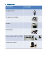
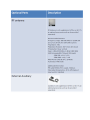
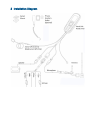
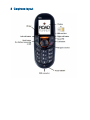
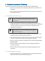
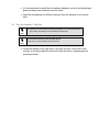
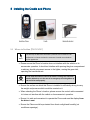
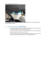
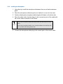
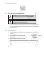
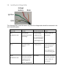
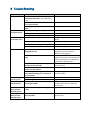
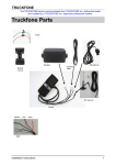
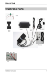
Car Phone installation guide Table of Content: 1 2 3 Carphone kit ............................................................................................................ 3 Installation Diagram................................................................................................. 5 Carphone layout ...................................................................................................... 6 4 Preplanned Accessory Positioning ............................................................................ 7 5 4.1 Plan Phone and Cradle Positions 7 4.2 Plan the Microphone’s Position 7 4.3 Plan the Speaker’s Position 8 Installing the Cradle and Phone ................................................................................ 9 5.1 Where to Position (Reminder) 9 5.2 Installing the Cradle and Phone 10 5.3 Installing the Microphone 11 5.4 5.5 Installing the Speaker Installing the Electrical Connections 13 14 5.6 Installing the Voltage Cable 15 5.7 Installing the Antenna 16 5.8 Installing the SIM card 18 6 Trouble Shooting ................................................................................................... 19 7 Appendix ............................................................................................................... 20 1 Carphone kit 2 Installation Diagram 3 Carphone layout 4 Preplanned Accessory Positioning 3B Positioning of all accessories must be planned in advance before installation begins. • Ensure that no wire braids go through locations where Phone accessories are to be installed. • Ensure that any parts of the handsfree Phone will not interfere with the vehicle or its accessories’ operation. 4.1 Plan Phone and Cradle Positions 7B Note! The best way to determine the Phone’s position to the customer’s full satisfaction is to locate it when the customer is beside you and obtain his/her approval. • Please ensure the Phone’s location does not interfere with the vehicle or its accessories operation: it should not interfere with opening the glove compartment or ashtray, should not prevent access to the lighter, moving the gear stick, operating the hand break etc. Warning! Do not install the Phone in front of the vehicle’s air bag. This restriction must be adhered to, as in the case of an emergency the air bag blows up and can fail to work properly. • Ensure the surface on which this Phone is installed is sufficiently strong to carry the weight and pressure which would be exerted on it. • When selecting the Phone’s location, please ensure the control cable connected to it does not interfere with the vehicle or its accessories’ operation. • Ensure it is safe and convenient to operate the Phone and read the display from the driver’s seat. • Ensure the Phone would be protected from direct sunlight and humidity (air conditioner openings). • Ensure the Phone would be protected from mechanical damage by the car’s accessories. 4.2 Plan the Microphone’s Position 8B • Install the handsfree Phone’s microphone 30-40 cm away from where the driver speaks when he/she is in their normal driving position. • It is recommended to install the microphone inbetween car roof and windscreen glass and away from external sources of noise. • Install the microphone in a different direction than the speaker so as to avoid echo. 4.3 Plan the Speaker’s Position 9B Note! The speaker and microphone (installed inbetween car roof and windscreen glass above the driver) must face different directions. Do not hide the speaker inside the dash board. If you cover it, sound quality will be lowered. Note! • Locate the speaker at the right side of the main console, at the front of the console, in a location where it would not bother the driver or passengers but would sound best. 5 Installing the Cradle and Phone 4B 5.1 Where to Position (Reminder) 10B Note! The best way to determine the Phone’s position to the customer’s full satisfaction is to locate it when the customer is beside you and obtain his/her agreement. • Please ensure the Phone’s location does not interfere with the vehicle or its accessories operation: it should not interfere with opening the glove compartment or ashtray, should not prevent access to the lighter, moving the gear stick, operating the hand break etc. Warning! Do not install the Phone in front of the vehicle’s air bag. This restriction must be adhered to, as in the case of an emergency the air bag blows up and can fail to work properly. • Ensure the surface on which this Phone is installed is sufficiently strong to carry the weight and pressure which would be exerted on it. • When selecting the Phone’s location, please ensure the control cable connected to it does not interfere with the vehicle or its accessories’ operation. • Ensure it is safe and convenient to operate the Phone and read the display from the driver’s seat. • Ensure the Phone would be protected from direct sunlight and humidity (air conditioner openings). • Ensure the Phone would be protected from mechanical damage by the car’s accessories. 5.2 Installing the Cradle and Phone 1B 1. Disassemble the cradle into its two parts. 2. Install one of the cradle parts in the determined location in the car with 4 tin screws. If you are not able to locate the cradle properly, please use a adjustable bracket from the station inventory. Note! 3. Install the second cradle part on the handsfree Phone, using the 4 philips screws provided with this kit. Only use the original screws provided with this kit. Note! 4. Connect the two cradle parts. 5. Direct the control cable coming out of the Phone behind the car panel. 5.3 Installing the Microphone 12B The microphone is provided with a clip which makes it possible to install it inbetween the car roof and windscreen glass. 5.3.1 Where to Locate the Microphone (Reminder) 18B • Install the handsfree Phone’s microphone 30-40 cm away from where the driver speaks when he/she is in their normal driving position. • It is recommended to install the microphone inbetween car roof and windscreen glass and away from external sources of noise. • Install the microphone in a different direction than the speaker so as to avoid echo, and ensure there is a distance of at least 1.5 meters between them. 5.3.2 Installing the Microphone 19B 1. Using the clip, install the microphone inbetween the car roof and windscreen glass. 2. Direct the microphone cable along the roof, behind it, so as not to be seen. 3. Continue directing the microphone cable along the left beam on the driver side. 4. Direct the cable under the dash board to the connection point of the cable with the control cable connected to the Phone. Note! Ensure the microphone cable and antenna cable are kept away from each other. Ensure the microphone cable is not in contact and does not interfere with the car pedals and steering wheel stick. 5. Connect the microphone cable plug to the correct port on the control cable. 5.4 Installing the Speaker 13B 5.4.1 Where to Locate the Speaker (Reminder) 20B Note! Note! The speaker and microphone (installed inbetween the car roof and windscreen glass above the driver) must face different directions. If the speaker and microphone face each other, this will cause echo. Do not hide the speaker inside the dash board. If you cover it, sound quality will be lowered. • Locate the speaker at the right side of the main console, at the front of the console, in a location where it would not bother the driver or passengers but would sound best. 5.4.2 Installing the Speaker 21B 1. Install the speaker at the right side of the main console, at the front of the console. 2. Disassemble the screws connecting the to the hanger. speaker 3. Install the hanger using the 2 tin screws. 4. Direct the speaker cable behind the mat located at the bottom of the car. 5. Ensure the cable does not interfere with the vehicle or its accessories’ operation. 6. Ensure the speaker cable is not exposed to damage by the passengers. 5.5 Installing the Electrical Connections The electrical cable is provided separately from the control cable. Before installation begins, connect the four leads (which include the 2A fuses) using a red or blue crimp sleeve as appropriate. Warning! Please note sharp edges or moving parts which may damage the wires. The value for the fuses provided with the kits must not be changed. The kit is appropriate only for a 12V vehicle. In case of converting any other kit model into this kit, please change the power cable. The electrical cables should be directed as follows: • So as not to disturb the driver or passengers. • So as not to pass near the car’s sharp or moving parts. Note! The external voltage connection is located under the dash board or close to the fuse box (depending on the car model). In new vehicles a cellular phone connection can be found near the fuse box. See the car’s user’s manual under Info. Only use the kit’s original fuses (250V / 2A). 5.6 Installing the Voltage Cable The following chart covers the manner by which the voltage cable should be connected to the car’s electrical system. Wire Color Function Must be connected to Ensure Red To provide the handsfree Phone with fixed voltage 12V fixed voltage Ensure a 250V / 2A fuse is used To provide a fixed minus (-) Car body (minus) Includes fuse case Black An additional fuse case is provided which must be connected to a fixed voltage source (+) Ensure the connection point is on the car body only. Use a cable shoe, tin screw and springy disc. Green Includes fuse case To turn on the cellular phone after switching the ignition on and turn it off after car ignition is switched off. IGN voltage Determine the correct point with a voltmeter Ensure a 250V / 2A fuse is used. 5.7 Installing the Antenna 16B 5.7.1 Where to Locate the Antenna 2B • The preferred location for the antenna is on the right side of the windshield. • If a cell phone or other communication system is installed in the car, please locate the antenna as far away as possible from the other Phone’s antenna. Remember! Some car models (such as Renault Megan and Renault Kangoo) feature a radiation filter on the windshield. Therefore it is necessary to install the antenna on a side or back window. In vehicles with air bags on the beam where the antenna cable passes, the antenna cable should be directed behind or beside the airbag. Note! 5.7.2 Installing the Antenna 5.7.2.1 Installing the External Adapter and Antenna Rod 23B 24B 1. Thoroughly clean the location intended for installation on both sides of window using a cloth and detergent. Allow the spot to dry before you continue. 2. Carefully remove the clear plastic cover protecting the external adapter (the antenna base). 3. Locate the adapter on the cleaned location. Ensure the adapter is stably placed in a horizontal position parallel to the window border. 4. Carefully press the antenna base toward the window. Ensure all corners of the adapter are attached to the window and the antenna rod is in a vertical position. 5.7.2.2 Installing the Internal Adapter and Coaxial Cable 25B 5. Carefully remove the clear plastic cover protecting the internal adapter. 6. Move the adapter, on the inside of the window, toward the antenna base (the external adapter), and direct the adapter so as to fully overlap the base. 7. Carefully press the antenna adapter to the window. Ensure all adapter corners are attached to the window. 8. Direct the antenna’s coaxial cable along the car beam. Ensure the antenna cable does not get damaged. Note! Do not direct the microphone cable and antenna cable together on the same beam (lintel). 9. When completing the cable’s installation and reaching close to the control cable connected to the Phone, please leave approximately 30 cm of additional wire and cut off the unnecessary extra cable. 10. Press a connector at the end of the cable. Use the original plug and pressers only. 11. Examine the antenna and cable’s proper working order with an efficiency meter. 5.8 Installing the SIM card 17B See SIM card installation position: In Note! Insert the SIM card when the phone is off. 6 Trouble Shooting Symptom No reception 26B What to Check Check whether connector is correctly connected to the cable – use an efficiency meter Check if internal and external antenna base is correctly attached Check proper working order of antenna cable Check speaker’s proper working order A Phone problem may exist Check speaker location Check microphone and contacts Other party cannot be properly heard 27B 28B User is not heard by the other party Replace Phone Change location Replace microphone A Phone problem may exist Replace Phone Ask whether noise always occurs in specific geographical areas Explain that reception trouble sometimes occurs in transition between coverage areas Explain that the Phone is an amplifying system that receives all environmental noise, and therefore it is preferable to speak with a closed window If they are, install microphone as per the instructions If it does, change location accordingly Ask whether noise occurs when window is open Phone does not switch off after switching off car Phone does not switch off after switching off car Replace speaker Check microphone’s proper working order 32B Phone switches on and off by itself Phone switches on and off by itself Replace antenna cable Check routing of microphone cable 31B Noise is heard Attach antenna base Tighten microphone connector to the Phone Change routing of microphone cable 29B 30B 3B What to Do Replace connector Check whether microphone and antenna are installed on the same side Check whether eye contact exists between speaker and microphone Check for improper voltage connection – check whether voltages are connected as per instructions Check minus (-) connection Check voltage contacts Check fuse. Check connection to voltage source (green cable) Check connection to power source (green cable) Check connection to power source. Check fuse (red cable) Change voltage source in accordance with instructions Black wire: connect minus to car body Tighten loose contacts Replace fuse. Tighten connection to voltage source. Ensure a 250V / 2A fuse is used Tighten connection to power source Replace fuse. Tighten connection to power source 7 Appendix 6B Finding IMEI code 1. Type code *#06# 2. Find locking code *5625#