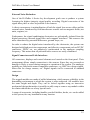
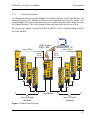
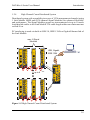
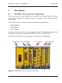
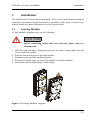
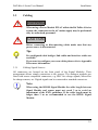
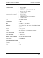
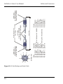
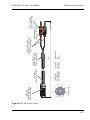
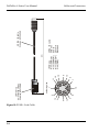
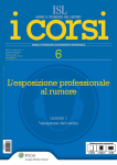
1
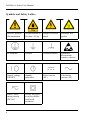
DATaRec 4 Series User Manual
!
Before putting the product into operation for
the first time, make sure to read the following
Safety Instructions
!
It is your responsibility to use the product in an appropriate manner. This product is
designed for use solely in industrial and laboratory environments or in the field and
must not be used in any way that may cause personal injury or property damage. You
are responsible if the product is used for an intention other than its designated
purpose or in disregard of the manufacturer's instructions. The manufacturer shall
assume no responsibility for such use of the product.
The product is used for its designated purpose if it is used in accordance with its
product documentation and within its performance limits. Using the product requires
technical skills and a basic knowledge of English. It is therefore essential that the
product be used exclusively by skilled and specialized staff or thoroughly trained
personnel with the required skills. If personal safety gear is required for using Heim
Systems products, this will be indicated at the appropriate place in the product
documentation.
Observing the safety instructions will help prevent personal injury or damage of any
kind caused by dangerous situations. Therefore, carefully read through and adhere to
the following safety instructions before putting the product into operation. It is also
absolutely essential to observe the additional safety instructions on personal safety
that appear in relevant parts of the product documentation. In these safety
instructions, the word "product" refers to all merchandise sold and distributed by the
Heim Systems, including instruments, systems and all accessories.
i
DATaRec 4 Series User Manual
Symbols and Safety Lables
ii
Observe product
documentation
Weight indication
for units >18 kg
Danger of electric
shock
Warning! Hot
surface
PE terminal
Ground
Ground terminal
Attention!
Electrostatic
sensitive decices
Supply voltage
ON/OFF
Standby
indication
Direct current
(DC)
Alternating
current (AC)
Direct / alternating current
(DC/AC)
Device fully protected by double /
reinforced
insulation
DATaRec 4 Series User Manual
Tags and their Meaning
!
!
!
DANGER
This tag indicates a definite hazard carrying a high risk of death
or serious injury if not avoided.
WARNING
This tag indicates a possible hazard carrying a medium risk of
death or (serious) injury if not avoided.
CAUTION
This tag indicates a hazard carrying a low risk of minor or
moderate injury if not avoided.
NOTICE
This tag indicates the possibility of incorrect use that can cause
damage to the product.
Note:
The bubble indicates important details. Equipment malfunction
may result if they are ignored.
Tip:
Special remarks are marked with a bulb.
These tags are in accordance with the standard definition for civil applications in the
European Economic Area. Definitions that deviate from the standard definition may
also exist in other economic areas or military applications. It is therefore essential to
make sure that the tags described here are always used only in connection with the
related product documentation and the related product. The use of tags in connection
with unrelated products or documentation can result in misinterpretation and thus
contribute to personal injury or material damage.
iii
DATaRec 4 Series User Manual
Basic Safety Instructions
1. The product may be operated only under the operating conditions and in the
positions specified by the manufacturer. Its ventilation must not be obstructed
during operation.
2. Applicable local or national safety regulations and rules for the prevention of
accidents must be observed in all work performed. The product may be opened
only by authorized, specially trained personnel. Prior to performing any work on
the product or opening the product, the product must be disconnected from the
supply network. Any adjustments, replacements of parts, maintenance or repair
must be carried out only by technical personnel authorized by Heim Systems.
Only original parts may be used for replacing parts relevant to safety (e.g. power
switches, power transformers, fuses). A safety test must always be performed
after parts relevant to safety have been replaced (visual inspection, PE conductor
test, insulation resistance measurement, leakage current measurement, functional
test).
3. As with all industrially manufactured goods, the use of substances that induce an
allergic reaction (allergens, e.g. nickel) such as aluminum cannot be generally
excluded. If you develop an allergic reaction (such as a skin rash, frequent
sneezing, red eyes or respiratory difficulties), consult a physician immediately to
determine the cause.
4. If products/components are mechanically and/or thermically processed in a
manner that goes beyond their intended use, hazardous substances (heavy-metal
dust such as lead, beryllium, nickel) may be released. For this reason, the product
may only be disassembled, e.g. for disposal purposes, by specially trained
personnel. Improper disassembly may be hazardous to your health. National
waste disposal regulations must be observed.
5. Depending on the function, certain products can produce an elevated level of
electromagnetic radiation. Considering that unborn life requires increased
protection, pregnant women should be protected by appropriate measures.
Persons with pacemakers may also be endangered byelectromagnetic radiation.
The employer/operator is required to assess workplaces where there is a special
risk of exposure to radiation and, ifnecessary, take measures to avert the danger.
6. Operating the products requires special training and intense concentration. Make
certain that persons who use the products are physically, mentally and
emotionally fit enough to handle operating the products; otherwise injuries or
iv
DATaRec 4 Series User Manual
material damage may occur. It is the responsibility of the employer to select
suitable personnel for operating the products.
7. Prior to switching on the product, it must be ensured that the nominal voltage
setting on the product matches the nominal voltage of the AC supply network. If
a different voltage is to be set, the power fuse of the product may have to be
changed accordingly.
8. In the case of products of safety class I with movable power cord and connector,
operation is permitted only on sockets with earthing contact and protective earth
connection.
9. Intentionally breaking the protective earth connection either in the feed line or in
the product itself is not permitted. Doing so can result in the danger of an electric
shock from the product. If extension cords or connector strips are implemented,
they must be checked on a regular basis to ensure that they are safe to use.
10. If the product has no power switch for disconnection from the AC supply, the
plug of the connecting cable is regarded as the disconnecting device. In such
cases, it must be ensured that the power plug is easily reachable and accessible at
all times (corresponding to the length of connecting cable, approx. 2 m).
Functional or electronic switches are not suitable for providing disconnection
from the AC supply. If products without power switches are integrated in racks
or systems, a disconnecting device must be provided at the system level.
11. Never use the product if the power cable or the power connector is damaged.
Check the power cable and the power connector on a regular basis to ensure that
it is in proper operating condition. By taking appropriate safety measures and
carefully laying the power cable, ensure that the cable cannot be damaged and
that no one can be hurt by e.g. tripping over the cable or suffering an electric
shock.
12. Do not insert the plug into sockets that are dusty or dirty. Insert the plug firmly
and all the way into the socket. Otherwise, this can result in sparks, fire and/or
injuries.
13. Do not overload any sockets, extension cords or connector strips; doing so can
cause fire or electric shocks.
14. For measurements in circuits with voltages Vrms > 30 V, suitable measures (e.g.
appropriate measuring equipment, fusing, current limiting, electrical separation,
insulation) should be taken to avoid any hazards.
v
DATaRec 4 Series User Manual
15. Ensure that the connections with information technology equipment comply with
IEC 950/EN 60950.
16. Unless expressly permitted, never remove the cover or any part of the housing
while the product is in operation. Doing so will expose circuits and components
and can lead to injuries, fire or damage to the product.
17. If a product is to be permanently installed, the connection between the PE
terminal on site and the product's PE conductor must be made first before any
other connection is made. The product may be installed and connected only by a
license electrician.
18. For permanently installed equipment without built-in fuses, circuit breakers or
similar protective devices, the supply circuit must be fused in such a way that
suitable protection is provided for users and products.
19. Do not insert any objects into the openings in the housing that are not designed
for this purpose. Never pour any liquids onto or into the housing. This can cause
short circuits inside the product and/or electric shocks, fire or injuries.
20. Use suitable overvoltage protection to ensure that no overvoltage (such as that
caused by a thunderstorm) can reach the product. Otherwise the operating
personnel will be endangered by electric shocks.
21. Heim Systems products are not protected against penetration of water, unless
otherwise specified (see also safety instruction 1.). If this is not taken into
account, there exists the danger of electric shock for the user or damage to the
product, which can also lead to personal injury.
22. Never use the product under conditions in which condensation has formed or can
form in or on the product, e.g. if the product was moved from a cold to a warm
environment.
23. Do not close any slots or openings on the product, since they are necessary for
ventilation and prevent the product from overheating. Do not place the product
on soft surfaces such as sofas or rugs or inside a closed housing, unless this is well
ventilated.
24. Do not place the product on heat-generating devices such as radiators or fan
heaters. The temperature of the environment must not exceed the maximum
temperature specified in the data sheet.
vi
DATaRec 4 Series User Manual
25. Batteries and storage batteries must not be exposed to high temperatures or fire.
Keep batteries and storage batteries away from children. Do not short-circuit
batteries and storage batteries. If batteries or storage batteries are improperly
replaced, this can cause an explosion (warning: lithium cells). Replace the battery
or storage battery only with the matching Heim Systems type. Batteries and
storage batteries must be recycled and kept separate from residual waste.
Batteries and storage batteries that contain lead, mercury or cadmium are
hazardous waste. Observe the national regulations regarding waste disposal and
recycling.
26. Please be aware that in the event of a fire, toxic substances (gases, liquids etc.)
that may be hazardous to your health may escape from the product.
27. The product can be very heavy. Be careful when moving it to avoid back or other
physical injuries.
28. Do not place the product on surfaces, vehicles, cabinets or tables that for reasons
of weight or stability are unsuitable for this purpose. Always follow the
manufacturer's installation instructions when installing the product and fastening
it to objects or structures (e.g. walls and shelves).
29. Handles on the products are designed exclusively for personnel to hold or carry
the product. It is therefore not permissible to use handles for fastening the product
to or on means of transport such as cranes, fork lifts, wagons, etc. The user is
responsible for securely fastening the products to or on the means of transport and
for observing the safety regulations of the manufacturer of the means of transport.
Noncompliance can result in personal injury or material damage.
30. If you use the product in a vehicle, it is the sole responsibility of the driver to
drive the vehicle safely. Adequately secure the product in the vehicle to prevent
injuries or other damage in the event of an accident. Never use the product in a
moving vehicle if doing so could distract the driver of the vehicle. The driver is
always responsible for the safety of the vehicle. The manufacturer assumes no
responsibility for accidents or collisions.
31. If a laser product (e.g. a CD/DVD drive) is integrated in a Heim Systems product,
do not use any other settings or functions than those described in the product
documentation. Otherwise this may be hazardous to your health, since the laser
beam can cause irreversible damage to your eyes. Never try to take such products
apart, and never look into the laser beam.
vii
DATaRec 4 Series User Manual
32. While operating the product, the housing and especially the heat sinks may
become hot.
Note:
viii
All trademarks acknoledged Heim Systems reserves the right to
amend these manual without notice. This manual is provided for
guidance only and does not constitute a warranty of any kind.
DATaRec 4 Series User Manual
Issue May 2007
Table of Contents
1
Introduction
1.1
1.2
General Information
Applications
1-1
1-1
1-4
1.2.1
1.2.2
1.2.3
1.2.4
Single Module Stand-Alone System
Compact System
Distributed System
High Channel Count Distributed System
1-4
1-5
1-7
1-9
1.3
Accessories
2
Description
2.1
2.2
DATaRec 4 Series System Components
Available Components
2-1
2-1
2-2
2.2.1
2.2.2
2.2.3
2.2.4
Signal Modules General Description
Link Modules
Power Modules
External Power Supplies
2-2
2-11
2-16
2-18
2.3
2.4
2.5
Connections Between Modules
Remote Control and Configuration Software
DATWare Libary
3
Installation
3.1
3.2
3.3
Locking Modules
Separating Modules
Cabling
3-1
3-1
3-2
3-3
3.3.1
3.3.2
3.3.3
3.3.4
3.3.5
Cabling Signal Sources
Cabling a Single Module Stand-Alone System
Cabling a Compact System
Cabling a Distributed System
Cabling a High Channel Count Distributed System
3-3
3-4
3-5
3-7
3-9
4
Operation
4.1
Front-End Operation
4-1
4-1
1-11
2-19
2-20
2-21
ix
DATaRec 4 Series User Manual
Issue May 2007
A
Technical Specification
A.1
A.2
General
Analoge Signal Modules
A.2.1
A.2.2
A.2.3
Direct Voltage / ICP Sensor Module - DIC6B / DIC6L
High Channel Count Voltage / ICP Sensor Module - DIC24
Charge Sensor Module - CHG6
A.3
Digital Signal Modules
A-10
A.3.1
Volt / EBU Module - DEBU
A-10
A.4
Power Modules
A.4.1
A.4.2
DC Power Module - PWD9
AC Power Module - PWAC
A.5
Link Modules
A.5.1
A.5.2
A.5.3
A.5.4
General
2-Channel Link Module - LMF2
4-Channel Link Module - LMF4
8-Channel Link Module - LMF8
A-16
A-18
A-18
A-18
B
Cables and Connectors
B.1
B.2
Cables
Connectors
B-1
B-1
B-6
B.2.1
B.2.2
B.2.3
B.2.4
CHG6 - 6-Channel Charge Input Module
B-6
DIC6B / DIC6L - 6-Channel Direct Voltage and ICP Sensor Module B-6
DIC24 - 24-Channel Direct Voltage and ICP Sensor Module
B-7
DEBU - 4-Channel Direct Voltage and ICP Sensor Module
B-9
C
Link Module Configurations
x
A-1
A-1
A-2
A-2
A-5
A-7
A-14
A-14
A-15
A-16
C-1
DATaRec 4 Series User Manual
1
Introduction
1.1
General Information
Introduction
The DATaRec 4 Series represents a totally modular data acquisition and signal
conditioning system, which can be tailored to a multitude of applications. This
flexible design provides the basis to configure large multi-channel systems as well
as small systems consisting of only one Signal Module for mobile applications. The
DATaRec 4 Series is the result of a Heim Systems’ continuous and market-driven
development of data acquisition systems. Many years of expertise and experience in
both the automotive and harsh environment flight test industry have been the bases
for this new range incorporating state of the art technology.
Figure 1-1 DATaRec 4 Series Modular Data Acquisition and Signal Conditioning
System (Example)
1-1
DATaRec 4 Series User Manual
Introduction
DATaRec 4 Series key facts:
•
•
•
•
•
•
•
•
•
•
•
•
Modular architecture for quasi infinite channel count
Design provides centralised or decentralised configuration
System architecture offers total flexibility for user configurations
IEEE1394b, USB 2.0, and Ethernet as standard interfaces to analysis systems
Signal modules with integrated signal conditioning (microphone, strain gauge,
accelerometer, pressure, ICP, etc.)
TEDS sensor identification for easy configuration of multi channel systems
Special signal modules for digital data (AES/EBU, CAN, etc.)
Digital data processing for maximum accuracy
24 bit A/D converter
100dB dynamic; <0.2° phase error
Modules galvanically isolated
Compact and robust design for mobile application
The DATaRec 4 Series supports among others:
•
•
•
•
•
•
ICP microphones
ICP vibration sensors
Charge outputs
Strain gage bridges
AES/EBU digital audio inputs
Tacho sensors
All of the DATaRec 4 Series input/output modules can be mixed in any combination
and can be configurated independently.
1-2
DATaRec 4 Series User Manual
Introduction
External Noise Reduction
One of the DATaRec 4 Series key development goals was to produce a system
featuring the highest integrity signal quality recording. Digital conversion of the
signal takes place as close as possible to the sensors.
A direct consequence is minimilisation of both the signal loss across cables and the
external noise, introduced by field interference sources such as magnetic fields, test
units, engines, etc.
Furthermore, the signal conditioning electronics are galvanically isolated from the
digital processors, internal signal lines and computer interfaces. This removes the
noise introduced by potential differences, ground loops, etc.
In order to reduce the digital noise introduced by the electronics, the system was
designed with high precision components, and all active components such as DC/DC
converters, FPGA, etc. are adaptively synchronised to the analogue sampling
frequency. This means that all potential noise sources are easily eliminated.
Signal Connectors and Link Interfaces
All connectors, displays and control elements are located on the front panel. Their
arrangement allows simple connection to the sensors. Since they are recessed no
damage is likely to occur during transport or operation of the system. The analogue
modules are fitted with sensor compatible connectors, e.g. BNC for voltage signals,
Micro-Dot for charge sensors, etc. Digital signals can be connected to standard
connectors.
Design
The rugged modules are made of milled aluminium, which ensures reliability in the
demanding environment to which the system is often subjected. All modules have
the same height and depth. They can be locked together using an innovative
mechanical design that makes it possible to add, swap or remove any module within
the chain without the use of any special tools.
A range of accessories, including handles, seat belt holders, hooks, etc. can be added
to the system, for easy installation in any location.
1-3
DATaRec 4 Series User Manual
1.2
Applications
1.2.1
Single Module Stand-Alone System
Introduction
In this application one signal module is directly connected to the computer via the
USB 2.0 interface. The power supply of the signal module is made by an external
power supply of 18 to 28 V (typical 24 V).
The maximum measurement channel count may range from 6 (using a 6 channel
module) to 24 (using a 24 channel module).
One channel of a Signal Module can be defined as a RPM channel. In this way either
6 analog channels or 5 analog channels and 1 RPM channel are available when using
a 6 channel module. When using a 24 channel module either 24 analog channels or
23 analog channels and 1 RPM channel are available.
USB
external power
supply
18 to 28 V
Figure 1-2 Single Module Stand-Alone System
1-4
DATaRec 4 Series User Manual
1.2.2
Introduction
Compact System
In a Compact System Signal Modules are linked together via a Link Module. All
modules build-up the Compact System are fitted mechanically together.
Interconnection of the modules is made by cable bridges.
PC interfacing is made via built-in USB 2.0, IEEE 1394b or Gigabit Ethernet link of
the Link Module.
The power supply of the compact system is made either by the Power Module(s)
PWD9 for DC supply or PWAC for AC supply
USB, Gigabit,
IEEE 1394
max. 8 Signal
Modules
max. 8 Signal
Modules
cable bridge
Figure 1-3 Compact System
1-5
DATaRec 4 Series User Manual
Introduction
The maximum measurement channel count depends on the Link Modules and on the
Signal Modules beeing used:
Link
Module
LMFx
max. Signal
Modules
6-channel Modules
24-channel Modules
2
2x8
96
384
4
4x8
192
768
8
8x8
384
1536
1-6
max. Channels
DATaRec 4 Series User Manual
1.2.3
Introduction
Distributed System
In a Distributed System Signal Modules are linked together via a Link Module. All
modules build-up the Distributed System are interconnected via link cables. The
Signal Modules are interconnected via up to 10 meter long data link cables between
the Signal Modules. The cable length within one chain must not exceed 50 m.
PC interfacing is made via built-in USB 2.0, IEEE 1394b or Gigabit Ethernet link of
the Link Module.
USB, Gigabit,
IEEE 1394
max. 50 m
max.
10 m
max. 50 m
max.
10 m
Link cables
max. 8 Signal
Modules
max. 8 Signal
Modules
Figure 1-4 Distributed System
1-7
DATaRec 4 Series User Manual
Introduction
The maximum measurement channel count depends on the Link Modules and on the
Signal Modules beeing used:
Link
Module
LMFx
max. Signal
Modules
6-channel Modules
24-channel Modules
2
2x8
96
384
4
4x8
192
768
8
8x8
384
1536
1-8
max. Channels
DATaRec 4 Series User Manual
1.2.4
Introduction
High Channel Count Distributed System
Distributed system with a capability in excess of 1536 measurement channels (using
1 Link Module LMF8 and 64 24-channel Signal Modules) for enhanced flexibility
and performance. The Signal Modules groups are interconnected via up to 10 meter
long data link cables to the Link Module. The cable length within one chain must not
exceed 50 m.
PC interfacing is made via built-in USB 2.0, IEEE 1394b or Gigabit Ethernet link of
the Link Module.
max. 8 Signal
Modules
USB, Gigabit,
IEEE 1394
ma
x.
10
m
ma
x.
10
m
up to 8
Figure 1-5 High Channel Count Distributed System
1-9
DATaRec 4 Series User Manual
Introduction
The maximum measurement channel count depends on the Link Modules and on the
Signal Modules beeing used:
Link
Module
LMFx
max. Signal
Modules
6-channel Modules
24-channel Modules
2
2x8
96
384
4
4x8
192
768
8
8x8
384
1536
1-10
max. Channels
DATaRec 4 Series User Manual
1.3
Introduction
Accessories
Link Cable:
• 0.14 m (cable bridge)
• 1.0 m
• 2.0 m
• 3.0 m
• 5.0 m
• 10 m
Order no. HW350-0005
Order no. HW350-0011
Order no. HW350-0012
Order no. HW350-0013
Order no. HW350-0020
Order no. HW350-0030
Power Cable:
• Link Power Cable 1 m (LEMO / Banana Plug) Order no. HW350-0050
• PWD9 Power Cable
Order no. HW630251
USB Cable:
• Link USB Cable 2 m (LEMO / USB)
Order no. HW630247
Adapter Cables:
• 50-pin Sub-D to 24 x BNC (female)
• 50-pin Sub-D to 24 x BNC (male)
Order no. HS350-1125
Order no. HS350-1120
Auto / Air Adapter:
Order no. HS300-1200
Li-Ion Power Pack:
Order no. HS300-1205
1-11
DATaRec 4 Series User Manual
1-12
Introduction
DATaRec 4 Series User Manual
Description
2
Description
2.1
DATaRec 4 Series System Components
The various sensor or data signals are connected to the Signal Modules. Special
Signal Modules support all common sensors. All modules can be configured in any
combination.
A DATaRec 4 Series system consists of the followinng components:
•
•
•
Signal Modules
Link Module
Power Module
The picture below shows a system configuration where a Link Module provides the
interface to the analysis computer (via USB 2.0, Ethernet, IEEE 1394b).
Detailed functionality of the components is described in the following.
Power Module
Signal Modules
Link Module
Signal Modules
Figure 2-1 DATaRec 4 Series System Components
2-1
DATaRec 4 Series User Manual
2.2
Description
Available Components
The following standard-frequency Signal Modules are available:
- CHG6
6-Channel Charge Input Module
- DIC6B
6-Channel Direct Voltage and ICP Sensor Module (single ended)
- DIC6L
6-Channel Direct Voltage and ICP Sensor Module (single ended and
differential))
- DIC24
24-Channel Direct Voltage and ICP Sensor Module (single ended)
- DEBU
4-Channel Direct Voltage and ICP Sensor Module (single ended)
The following Power Modules are available:
- PWD9
Power Module with DC input
- PWDAC Power Module with AC input
The following Link Modules are available:
- LMF2
Link Module for connecting 2 subsystems
- LMF4
Link Module for connecting 4 subsystems
- LMF8
Link Module for connecting 8 subsystems
2.2.1
Signal Modules General Description
The Signal Modules provide the interface to the different signal sources to be
measured. A range of individual Signal Modules can be used for signal conditioning
of different sensors or data sources. A maximum of 24 channels can be connected to
one Signal Module. Input signal levels are easily seen on the display and overload
LED’s. The display is also used to identify the module within a decentralised
configuration by showing each unique module number.
The Signal Module performs the signal conditioning and the A/D conversion (24bit).
Each channel is completely independent and consists of sensor support (e.g. power),
amplifier and A/D converter.
In terms of accuracy, measurement speed, and noise characteristics these state-ofthe-art Signal Modules are unparalleled. All modules have their own power supplies
as well as their own internal calibration sections. The modules are galvanically
isolated and sample rate can be set for each module depending on the system sample
rate.
2-2
DATaRec 4 Series User Manual
Description
A special feature is the overload detection. An overload situation will be detected by
means of a comparator in front of the A/D converter, allowing you to detect high
amplitude unwanted frequencies.
Each channel can be used as a signal channel or one of them can be used as RPM
channel and the remaining channels can be used as signal channels.
One Signal Module can be connected directly to the USB 2.0 interface of a PC. Up
to 64 (8x8) Signal Modules can be connected to a Link Module to provide a multichannel system.
DIC6B / DIC6L - 6-Channel Direct Voltage and ICP Sensor Module
6
1
1.
2.
3.
4.
5.
6.
Display
Signal input connectors
USB connector
Link connectors
Channel LEDs
Button
5
2
3
4
Figure 2-2 DIC6B - 6-Channel Direct Voltage and ICP Sensor Module
Tip:
At the DIC6L module the BNC connectors are replaced by LEMO
connectors.
2-3
DATaRec 4 Series User Manual
Description
Display
On the display input signal levels can be seen.
The display is also used to identify the module within
a decentralised configuration by showing the unique
module number.
Signal input connectors
The module is fitted with sensor compatible
connectors, e.g. BNC for voltage signals.
USB connector
One module can be connected directly to a PC using
the USB 2.0 interface.
Link connectors
In a system configuration the connection between the
different modules is implemented by means of a
simple cable bridge or by means of link cables.
Channel LEDs
The input signal level situation of a channel will be
shown by the appropriate multi colour LED.
green: Input signal level is in the right range.
red: Channel is in an overload situation.
blue: Channel is a RPM channel.
Button
The button is used to calibrate the module or to select
a channel for displaying its input signal level:
• Pressing the button once shorter 5 s will
sequentially select a channel for displaying its
input signal level. The LED of the selected channel
will light brighter.
• Pressing the button once longer 5 s and than
releasing it will start the module calibration.
2-4
DATaRec 4 Series User Manual
Description
DIC24 - 24-Channel Direct Voltage and ICP Sensor Module
1
2
7
6
1.
2.
3.
4.
5.
6.
7.
Display
Signal input connector
USB connector
Link connectors
RPM / IPC LED
Channel LEDs
Button
5
3
4
Figure 2-3 DIC24 - 24-Channel Direct Voltage and ICP Sensor Module
Display
On the display input signal levels can be seen.
The display is also used to identify the module within
a decentralised configuration by showing the unique
module number.
Signal input connector
The modules are normally fitted with sensor
compatible connectors, e.g. BNC for voltage signals,
Micro-Dot for charge sensors, etc. Here a standard 50pin D-Sub connector is used as signal input connector.
Note: Adapter cables from 50-pin D-Sub to 24 x BNC
(female) and from 50-pin D-Sub to 24 x BNC (male)
are available as accessorie.
USB connector
One module can be connected directly to a PC using
the USB 2.0 interface.
2-5
DATaRec 4 Series User Manual
Description
Link connectors
In a system configuration the connection between the
different modules is implemented by means of a
simple cable bridge or by means of link cables.
RPM / ICP LED
Lights if channel 24 of the module is used as RPM
channel or the ICP is connected.
Channel LEDs
The input signal level situation of a channel group will
be shown by the appropriate multi colour LED.
green: Input signal level is in the right range.
red: Channel is in an overload situation.
Button
The button is used to calibrate the module or to select
a channel for displaying its input signal level:
• Pressing the button once shorter 5 s will
sequentially select a channel for displaying its
input signal level. The LED of the selected channel
will light brighter.
• Pressing the button once longer 5 s and than
releasing it will start the module calibration.
Tip:
Adapter cables from 50-pin Sub-D to 24 x BNC (female) and from
50-pin Sub-D to 24 x BNC (male) are available as accessories.
2-6
DATaRec 4 Series User Manual
Description
DEBU - 4-Channel Direct Voltage and ICP Sensor Module
1
6
1.
2.
3.
4.
5.
6.
Display
Signal input connectors
USB connector
Link connectors
Channel LEDs
Button
5
2
3
4
Figure 2-4 DEBU - 4-Channel Direct Voltage and ICP Sensor Module
Display
On the display input signal levels can be seen.
The display is also used to identify the module within
a decentralised configuration by showing the unique
module number.
Signal input connectors
The module is fitted with sensor compatible
connectors, e.g. BNC for voltage signals. Digital
signals can be connected to the standard 9-pin D-Sub
connector.
USB connector
One module can be connected directly to a PC using
the USB 2.0 interface.
2-7
DATaRec 4 Series User Manual
Description
Link connectors
In a system configuration the connection between the
different modules is implemented by means of a
simple cable bridge or by means of link cables.
Channel LEDs
The input signal level situation of a channel will be
shown by the appropriate multi colour LED.
green: Input signal level is in the right range.
red: Channel is in an overload situation.
blue: Channel is a RPM channel.
Button
The button is used to calibrate the module or to select
a channel for displaying its input signal level:
• Pressing the button once shorter 5 s will
sequentially select a channel for displaying its
input signal level. The LED of the selected channel
will light brighter.
• Pressing the button once longer 5 s and than
releasing it will start the module calibration.
2-8
DATaRec 4 Series User Manual
Description
CHG6 - 6-Channel Charge Input Module
1
2
6
1.
2.
3.
4.
5.
6.
Display
Signal input connectors
USB connector
Link connectors
Channel LEDs
Button
5
3
4
Figure 2-5 CHG6 - 6-Channel Charge Input Module
Display
On the display input signal levels can be seen.
The display is also used to identify the module within
a decentralised configuration by showing the unique
module number.
Signal input connectors
The module is fitted with sensor compatible
connectors, e.g. Micro-Dot for charge sensor signals.
USB connector
One module can be connected directly to a PC using
the USB 2.0 interface.
Link connectors
In a system configuration the connection between the
different modules is implemented by means of a
simple cable bridge or by means of link cables.
2-9
DATaRec 4 Series User Manual
Description
Channel LEDs
The input signal level situation of a channel will be
shown by the appropriate multi colour LED.
green: Input signal level is in the right range.
red: Channel is in an overload situation.
blue: Channel is a RPM channel.
Button
The button is used to calibrate the module or to select
a channel for displaying its input signal level:
• Pressing the button once shorter 5 s will
sequentially select a channel for displaying its
input signal level. The LED of the selected channel
will light brighter.
• Pressing the button once longer 5 s and than
releasing it will start the module calibration.
2-10
DATaRec 4 Series User Manual
2.2.2
Description
Link Modules
The Link Module is the central data handling unit for interconnection of multiple
Signal Modules to a system. Data acquired from the Signal Modules can be
transferred via IEEE 1394b, Gigabit Ethernet or USB 2.0 to an analysis computer or
to a storage device.
Since the Link Module provides a common time basis for the all connected Signal
Modules, extremely precise synchronisation of all signals is always ensured.
Furthermore the Link Module controls calibration, phase alignment, and system test
if a new system configuration is required.
Multi channel Link Modules can be used to connect up to eight link chains (using the
LMF8 Link Module) in order to create very high channel count (up to 1536 channels)
acquisition systems.
Tip:
For the various configurations of the Link Modules refer to
Appendix C.
2-11
DATaRec 4 Series User Manual
Description
Link Module LMF2FE
1
5
1. Display
2. Standard interface
connectors
3. LINK connectors
4. C-REM connector
5. Buttons
2
4
3
Figure 2-6 Link Module LMF2FE without Options
Tip:
The figure shows the Link Module LMF2FE without options. The
front panel layout with options differ in the count of the interface
connectors.
Display
The display is used to show status information.
Standard interface
connectors
The standard interfaces (USB 2.0, Gigabit Ethernet,
IEEE 1394b) can be used as interface to the analysis
computer.
2-12
DATaRec 4 Series User Manual
Description
Link connectors
In a system configuration the interconnection between
the different modules is implemented by means of
links cables via these connectors.
C-Rem connector
The C-REM connector provides a contact remote
interface with 7 digital input lines and 7 staus output
lines.
Buttons
The buttons are used for setup configurations.
Tip:
Data transfer via an interface will be indicated by the appropriate
LED.
2-13
DATaRec 4 Series User Manual
Description
Link Module LMF8
8
1
7
2
1. Display
2. Standard interface
connectors
3. LINK connectors
4. TIME connector
5. MEDIA connector
6. C-REM connector
7. Buttons
8. PC connector, rugged
design
6
5
4
3
Figure 2-7 Link Module LMF8 with all Options
Tip:
The figure shows the Link Module LMF8 without options. The
front panel layout with options differ in the count of the interface
connectors.
Display
The display is used to show status information.
Standard interface
connectors
The standard interfaces (USB 2.0, Gigabit Ethernet,
IEEE 1394b) can be used as interface to the analysis
computer.
2-14
DATaRec 4 Series User Manual
Description
Link connectors
In a system configuration the interconnection between
the different modules is implemented by means of
links cables via these connectors.
TIME connector
At the Time connector a GPS receiver or a IRIG-B
signal can be connected to supply the system with a
external time code signal.
MEDIA connector
The MEDIA connector provides an IEEE 1394b and
an USB 2.0 interface for connecting an external
storage media (e.g. a hard disc drive).
C-Rem connector
The C-REM connector provides a contact remote
interface with 7 digital input lines and 7 staus output
lines.
Buttons
The buttons are used for setup configurations.
PC connector
(rugged design)
The rugged design PC connector provides further
interfaces to the analysis computer (via USB 2.0,
Gigabit Ethernet, IEEE 1394b). This connector may
be used when the Link Module is used in a rugged
environment.
Note:
Only one of the IEEE 1394b interfaces can be used to connect a PC
or an external storage media at the same time.
Only one interface of the same type available as standard interface
and available at the PC connector may be used to connect the Link
Module to a PC at the same time.
Data transfer via all interfaces will be indicated by the
appropriate LED.
2-15
DATaRec 4 Series User Manual
2.2.3
Description
Power Modules
The power input voltage of all Signal and Link Modules of the DATaRec 4 Series
system is 18 to 28 V (typ. 24 V). Each module generates all internal voltages (e.g.
3 V, 12 V, etc.). The Power Modules converts a wide range of external supply
voltages to the 24 V system voltage. Power Modules are available for AC as well as
for DC supplies.
For decentralised system configurations Power Modules with repeater functionality
are available. In this case the Power Module also routes the data to the Link Module.
Parallel integrated Power Modules avoid voltage drops that normally occur in large
installations.
PWD9
1. Power LED
2. Power switch
3. Power input
connector
4. Fuse
5. Link connectors
1
2
1
PWAC
1. Power switch
2. Power input
connector
3. Power LED
4. Fan switch
5. Link connectors
3
2
4
5
3
4
5
Figure 2-8 Power Modules PWD9 and PWAC
Power LED
Lights when input power is available and the Power
Module is switched on.
Power switch
Switches the Power Module on / off.
2-16
DATaRec 4 Series User Manual
Description
Power input connector
PWD9: DC power input in the range 9 to 36 VDC.
Note: With an input voltage below 10 V the maximum
output power of 50 W cannot be ensured due to
tolerances of components.
PWAC: AC power input in the range 90 to 130 VAC
or 180 to 260 VAC without switchover.
Fuse
8 A fuse for the DC supply.
Link connectors
Distributes the power supply voltage to the Signal and
Link Modules and also routes the data to the Link
Module.
Fan switch
The fans within the Power Module PWAC are
temperature controlled, with the switch two different
temperature threshold values can be set. It is not an
on / off switch.
Left position: The fans are only switched on at a high
interior temperature, i.e. they do not run often.
Right position: The fans are switched on at a lower
interior temperature, i.e. they do run often.
Note:
Within each chain of Signal Modules at least one Power Module or
an external power supply must be integrated, since the Link
Module does not pass the supply voltage throughout to its other
link connectors.
Due to the high output power (max. 100 W per link connector) the
Power Module PWAC should always be integrated in the middle
of the chain of Signal Modules and not at the end.
!
CAUTION
While operating the DATaRec 4 Series system the heat sink of the
Power Module may be hot.
2-17
DATaRec 4 Series User Manual
Description
NOTICE
Do not connect other power input voltages to the Power Module as
the specified voltages.
The Power Module may only be used for its designated purpose. It
must not be used for any other purposes.
2.2.4
External Power Supplies
Additional to the system Power Modules a DC/DC Car Adapter and a Li-Ion Power
Pack are available as external power supplies.
Auto / Air Adapter
The Auto / Air Adpter maintains the power supply of the DATaRec 4 Series system
while using it within a car. The maximum output power of the Auto / Air Adapter is
60 W.
Li-Ion Power Pack
The slim, lightweight Li-Ion Power Pack is composed of Li-Ion prismatic batteries
with high energy density. The typical capacity is 140 Wh at a output voltage of 20 V.
Five LEDs allows you to check the remaining capacity. An AC adapter for
recharging is included.
NOTICE
The system Power Modules and the external power supplies Auto /
Air Adapter and Li-Ion Power Pack must not be connected to the
DATaRec 4 Series system together at the same time.
2-18
DATaRec 4 Series User Manual
2.3
Description
Connections Between Modules
The connection links provide the power supply to the modules and the
synchronisation and configuration of the system and transfer of acquired data. Data
transfer between each single module is performed over a proprietary 1.5 Gbit/s highspeed serial link. The connection is implemented in a compact system configuration
by means of a simple cable bridge or a link cable for a distributed system. The cables
may be up to 10 meter long between the signal modules and up to 50 meter for one
chain. Such a configuration allows you to install the measurement units close to the
signal sources, which therefore minimises the potentially complex sensor cabling
and the effect of any external interference.
!
CAUTION
Before connecting cables make sure that any power source is
disconnected.
NOTICE
Before connecting the link cables align the red points of the cable
connector and module connector.
2-19
DATaRec 4 Series User Manual
2.4
Description
Remote Control and Configuration Software
Remote control and configuration software HS_AX_xxxy (e.g. HS_AX_DIC6) as
well as remote control and configuration software FTrans allow configuration and
monitoring of DATaRec 4 Series systems. It can read the measurement data directly
from the inputs of the Signal Modules and it allows data transfer of recorded data to
your hard disc. All of these functions are controlled from a PC when the DATaRec
4 Series system is connected to the PC.
Figure 2-9 Remote control and configuration software HS_AX_DIC6
For more details please refer to the HS_AX_xxxy or FTrans User Manaul supplied
with the software.
2-20
DATaRec 4 Series User Manual
2.5
Description
DATWare Libary
To help the integration of any DATaRec recorder or DATaRec media into a user
analysis package the DATWare Libary, containing source code routines, is available.
It supports the following 32-bit Windows applications:
• Windows 2000 / XP
The DATWare Libary can be used with the following Heim devices:
•
•
•
Front-end mode operation with DATaRec-A480, -D12, -D20, DiSC6, GSR120,
GSR200 and DATaRec 4 Series.
Any tape, hard disc and solid state media recorded by these recorders.
Raw Files saved from any of these recorders or media, DATaRec-3 file format
and also IRIG-106 Chapter 10 file format.
The DATWare Libary supports the following basic data reading functions:
•
•
•
•
•
Help to find and identify the DATaRec devices on the SCSI bus or as Raw Data
Files.
Extract header information (e.g. range, sampling rate) for all channels to manage
configuration.
Convert multi-channel and multi-rate recorded analog channels into a data frame.
De-multiplex PCM frames into data words.
Conversion routines between the data formats.
The DATWare Libary supports the following basic control functions:
•
•
•
•
Help to find and identify the DATaRec devices on the SCSI bus or RS-232 serial
line or USB 2.0 interface (depends on device).
Get the current module and media configuration, control the operation.
Get the type of the channels and supply information about the properties of the
channels.
Get and set the current global and channel specific parameters of the recorder.
The DATWare Libary is free of charge and public for any end-users and third party
companies. No companies are allowed to sell this code - however everybody can
charge for products which contain this code and also all extension and modification
done by a 3rd party company can be commercially available.
2-21
DATaRec 4 Series User Manual
2-22
Description
DATaRec 4 Series User Manual
3
Installation
Installation
All modules have the same height and depth. They can be locked together using an
innovative mechanical design that makes it possible to add, swap or remove any
module within the chain without the use of any special tools.
3.1
Locking Modules
To lock modules together carry out the following:
!
CAUTION
Before connecting cables make sure that any power source is
disconnected.
1. Hold the right module in diagonal and insert the lower locking plate into the
recess of the left module.
2. Push the button at the top of the right module.
3. Simultaneously push the modules together.
4. Release the button at the top of the left module to lock the modules.
5. Interconnect the modules using a cable bridge.
Figure 3-1 Locking Modules Together
3-1
DATaRec 4 Series User Manual
3.2
Installation
Separating Modules
To separate modules carry out the following:
!
CAUTION
Before disconnecting cables make sure that any power source is
disconnected.
1. Disconnect the cable bridge between the modules.
2. Push the button at the top of the right module.
3. Tip the right module to the right and separate the modules.
Figure 3-2 Separating Modules
3-2
DATaRec 4 Series User Manual
3.3
Installation
Cabling
!
!
WARNING
When using a Power Module PWAC within the DATaRec 4 Series
system, the connection to the AC mains supply may be performed
only by authorized personnel.
CAUTION
Before connecting or disconnecting cables make sure that any
power source is disconnected.
Tip:
Pre-configured cable bridges, link cables and interface cables are
available.
If you want to configure your own cables please refer to Appendix
B for more information.
3.3.1
Cabling Signal Sources
All connectors are located on the front panel of the Signal Modules. Their
arrangement allows simple connection to the sensors. The analogue modules are
fitted with sensor compatible connectors, e.g. BNC for voltage signals, Micro-Dot
for charge sensors, etc. Digital signals can be connected to standard connectors.
Note:
When using the DIC6B Signal Module the cable length between
Signal Module and sensor must not exeed 3 m to avoid an
impairment of the EMV guidelines. If the cable length must be
longer than 3 m we recommended to use the DIC6L Signal
Module.
3-3
DATaRec 4 Series User Manual
3.3.2
Installation
Cabling a Single Module Stand-Alone System
In a Single Module Stand-Alone System one signal module is directly connected to
the computer via the USB 2.0 link. The power supply of the signal module is made
here via an external power supply of 18 to 28 V (typicall 24 V).
USB
external power
supply
18 to 28 V
Figure 3-3 Cabling a Single Module Stand-Alone System
3-4
DATaRec 4 Series User Manual
3.3.3
Installation
Cabling a Compact System
The connection within a compact system configuration is implemented by means of
a simple cable bridge. The connection links provide both the power supply to the
modules and the synchronisation and configuration of the system and transfer of
acquired data. Up to 8 signal modules can be linked together within a chain using a
Link Module.
The connection to the PC can be made via USB 2.0, Gigabit Ethernet or IEEE 1394b
interface.
USB, Gigabit,
IEEE 1394
max. 8 Signal
Modules
max. 8 Signal
Modules
cable bridge
Figure 3-4 Cabling a Compact System
3-5
DATaRec 4 Series User Manual
Installation
Note:
Within each chain of Signal Modules at least one Power Module or
an external power supply must be integrated, since the Link
Module does not pass the supply voltage throughout to its other
link connectors.
Note:
The maximum output power of the Power Module PWD9 is 50 W.
Therfore, when using the maximum count of Signal Modules it
may be necessary to insert a second Power Module within the
chain (depends on Signal Modules being used).
Note:
Due to the high output power (max. 100 W per link connector) the
Power Module PWAC should always be integrated in the middle
of the chain of Signal Modules and not at the end.
3-6
DATaRec 4 Series User Manual
3.3.4
Installation
Cabling a Distributed System
The connection within a distributed system configuration is implemented by means
of link cables between the Link Module, the Signal Modules and the Power Module.
The connection links provide both the power supply to the modules and the
synchronisation and configuration of the system and transfer of acquired data. Up to
8 Signal Modules can be linked together in one chain by using a Link Module. The
connection between Link Module and the PC can be made via USB 2.0, Gigabit
Ethernet or IEEE 1394b interface.
max. 50 m
USB, Gigabit,
IEEE 1394
max.
10 m
Link cables
max. 8 Signal
Modules
max. 8 Signal
Modules
Figure 3-5 Cabling a Distributed System
3-7
DATaRec 4 Series User Manual
Installation
Note:
Within each chain of Signal Modules at least one Power Module or
an external power supply must be integrated, since the Link
Module does not pass the supply voltage throughout to its other
link connectors.
Note:
The maximum output power of the Power Module PWD9 is 50 W.
Therfore, when using the maximum count of Signal Modules it
may be necessary to insert a second Power Module within the
chain (depends on Signal Modules being used).
Note:
Due to the high output power (max. 100 W per link connector) the
Power Module PWAC should always be integrated in the middle
of the chain of Signal Modules and not at the end.
Note:
The length of the link cables must not exceed 10 m. The length of
one chain is limited to 50 m.
3-8
DATaRec 4 Series User Manual
3.3.5
Installation
Cabling a High Channel Count Distributed System
The connection within each compact system configuration is implemented by means
of a cable bridges. The connection within the distributed system configuration is
implemented by means of link cables between the Link Module and the compact
systems. Up to 8 Compact Systems (subsystems) can be linked together using a
LMF8 Link Module. The connection between Link Module and the PC can be made
via USB 2.0, Gigabit Ethernet or IEEE 1394b interface.
max. 8 Signal
Modules
USB, Gigabit,
IEEE 1394
ma
x.
10
m
ma
x.
10
m
up to 8
Figure 3-6 Cabling a High Channel Count Distributed System
3-9
DATaRec 4 Series User Manual
Installation
Note:
Within each chain of Signal Modules at least one Power Module or
an external power supply must be integrated, since the Link
Module does not pass the supply voltage throughout to its other
link connectors.
Note:
The maximum output power of the Power Module PWD9 is 50 W.
Therfore, when using the maximum count of Signal Modules it
may be necessary to insert a second Power Module within the
chain (depends on Signal Modules being used).
Note:
Due to the high output power (max. 100 W per link connector) the
Power Module PWAC should always be integrated in the middle
of the chain of Signal Modules and not at the end.
Note:
The length of the link cables must not exceed 10 m.
3-10
DATaRec 4 Series User Manual
4
Operation
!
4.1
Operation
CAUTION
While operating the DATaRec 4 Series system the modules and
especially the heat sinks can become hot.
Front-End Operation
The DATaRec 4 Series is first development step designed for use as a front-end
without any storage media.
Heim Systems has integrated the front-end data transfer and configuration functions
into a Control and Signal Display program called HS_AX_xxxy (e.g.
HS_AX_DIC6), also the FTrans program can be used. It can read the measurement
data directly from the inputs of the DATaRec 4 Series system and it allows data
transfer to your hard disc. All of these functions are controlled from a PC when the
DATaRec 4 Series system is connected to a PC using the USB 2.0, Gigabit Ethernet
or IEEE 1394b interface.
Note:
For operating the DIC6 Control and Signal Display software,
please refer to the manual supplied with the program.
4-1
DATaRec 4 Series User Manual
4-2
Operation
DATaRec 4 Series User Manual
A
Technical Specification
Technical Specification
CAUTION
!
A.1
While operating the DATaRec 4 Series system the modules can be
become hot, so that the temperature may reach into values higher
as the specified operating temperature.
General
Configuration
Number of channels
6 to 1536
Number of signal modules
8 in a subsystem, 8 subsystems currently supported
Total bit rate
max. 600 Mbit/s to 1.5 Gbit/s, depending on signal
modules, sampling frequencies, computer interfaces,
storage media type
Analoge inputs
•
•
•
•
Direct Voltage inputs
Microphone
Charge and Straingauge
ICP sensors
Digital inputs
•
•
AES / EBU
CAN
Computer Interfaces
•
•
•
IEEE 1394b
USB 2.0
Gbit Ethernet (10/100/1000 Base T)
•
•
9 - 36 V DC or
90 - 130 V AC / 180 - 260 V AC (47 - 63 Hz)
Power Supply
Power supply voltage
A-1
DATaRec 4 Series User Manual
Technical Specification
A.2
Analoge Signal Modules
A.2.1
Direct Voltage / ICP Sensor Module - DIC6B / DIC6L
General
Number of channels
6
Sampling frequency (Fs)
500 Hz - 200 kHz, settable in steps of 10 Hz. Each
module can work with its own sampling frequency,
which is a binary divider of Fs.
Bandwidth
DC to max. 80 kHz (user-selectable)
Samplingr ratio
2.5; no mirroring effect
Dynamic range
>102 dB at 0 dBV range in DATaRec 4 Mode *
Dynamic range
>96 dB at 0 dBV range in DATaRec 3 Mode
Analoge to digital converter
24 bit
Data resolution
•
•
THD
<-90 dB at 0 dBV range
Phase Accuracy
<0.2° (without optional high or low pass filter)
AC Accuracy
±0.02 % or ±1 mV
DC Accuracy
±0.1 % or ±1 mV
Input impedance
•
•
Signal level
±10mVpeak to ±10Vpeak in 1x, 2x, 5x, 10x steps
Coupling
•
•
ICP power
24 V DC, 4 mA constant current
A-2
16 bit (DATaRec 3 Mode) or
32 bit * (DATaRec 4 Mode), selectable
1 MΩ (DIC6L differential mode)
500 kΩ (DIC6B single ended)
DC
AC (-3dB at 0.2 Hz)
DATaRec 4 Series User Manual
Technical Specification
TEDS sensor identification
IEEE 1451.4 standard for all 6 channels
Analog high pass filter
(optional)
22 Hz
Analoge low pass filter
(optional)
500 Hz, 1 kHz or 4 kHz
RPM channel
one channel is useable as RPM input
RPM sampling frequency
•
•
Threshold level
0 to 100 % of the selected amplifier step
Mode
•
•
DIC6B: Single Ended
DIC6L: Single Ended or Differential
Connectors
•
•
6 x BNC (DIC6B)
6 x 3 pin LEMO, differential (DIC6L)
Dimensions
37.1 x 184 x 124.5 mm (w x h x d) including fixing
system
Weight
940 g typical
Cooling
no fan
Power consumption
10 W typical
Power input range
17 to 28 V
Input DC power
Low power detection
Communication
built-in USB 2.0, RS-232 and high speed Link
interfaces
DATaRec 3 Mode: 16 x Fs (max. 3.2 MHz)
DATaRec 4 Mode: 32 x Fs (max. 6.4 MHz)
Functions
Integrated calibration unit
1 ppm reference calibration
Galvanic isolation
yes
A-3
DATaRec 4 Series User Manual
Technical Specification
Max. isolation voltage
•
•
48 V (power input)
48 V (digital / analog part)
Input channel voltage safety
±35 V
Joint mode
yes
Environmental specification
Vibration
5g
Shock
10 g
Operating temperature
-30 °C to +65 °C
Storage temperature
-40 °C to +90 °C
Humidity
0 – 95 % relative, non-condensing
* under development
A-4
DATaRec 4 Series User Manual
A.2.2
Technical Specification
High Channel Count Voltage / ICP Sensor Module - DIC24
General
Number of channels
24
Sampling frequency (Fs)
up to 50 kHz, settable in steps of 10 Hz. Each
module can work with its own sampling frequency,
which is a binary divider of Fs.
Bandwidth
max. 20 kHz (user-selectable)
Samplingr ratio
2.5; no mirroring effect
Dynamic range
>90 dB at 0 dBV range in DATaRec 3 Mode
Analoge to digital converter
24 bit
Data resolution
•
•
THD
<-90 dB at 0 dBV range
Phase Accuracy
<0.2°
AC Accuracy
±0.1 % or ±1 mV
Input impedance
1 MΩ
Signal level
±10mVpeak to ±10Vpeak
Coupling
AC (-3dB at 0.75 Hz)
ICP power
22 V DC, 4 mA constant current
TEDS sensor identification
IEEE 1451.4 standard for all 24 channels
RPM channel
channel 24 is useable as RPM input
RPM sampling frequency
DATaRec 3 Mode: 16 x Fs (max. 800 kHz)
Threshold level
0 to 100 % of the selected amplifier step
16 bit (DATaRec 3 Mode) or
32 bit * (DATaRec 4 Mode), selectable
A-5
DATaRec 4 Series User Manual
Technical Specification
Mode
Single Ended
Connectors
1 x 50 pin D-sub
Dimensions
48.1 x 184 x 124.5 mm (w x h x d) including fixing
system
Weight
1100 g typical
Cooling
no fan
Power consumption
15 W typical
Power input range
17 to 28 V
Input DC power
Low power detection
Communication
built-in USB 2.0, RS-232 and high speed Link
interfaces
Functions
Integrated calibration unit
1 ppm reference calibration
Galvanic isolation
yes
Max. isolation voltage
•
•
Input channel voltage safety
±35 V
Joint mode
yes
48 V (power input)
48 V (digital / analog part)
Environmental specification
Vibration
5g
Shock
10 g
Operating temperature
-30 °C to +65 °C
A-6
DATaRec 4 Series User Manual
Technical Specification
Storage temperature
-40 °C to +90 °C
Humidity
0 – 95 % relative, non-condensing
* under development
Note:
IF the ICP is activated on one channel than the 10 V input range
for the whole module will be disabled.
A.2.3
Charge Sensor Module - CHG6
General
Number of channels
6
Sampling frequency (Fs)
500 Hz - 200 kHz, settable in steps of 10 Hz. Each
module can work with its own sampling frequency,
which is a binary divider of Fs.
Bandwidth
DC to max. 80 kHz (user-selectable)
Samplingr ratio
2.5; no mirroring effect
Dynamic range
>90 dB at 1 nC range in DATaRec 3 Mode
Analoge to digital converter
24 bit
Data resolution
•
•
THD
<-95 dB at 5 nC range
Phase Accuracy
<0.2° (without optional high or low pass filter)
Accuracy
±0.1 % or ±1 pC
Input impedance
1013 Ω
Signal level
3 pCpeak to 10000 pCpeak in 1x, 3x, 6x, 10x steps
16 bit (DATaRec 3 Mode) or
32 bit * (DATaRec 4 Mode), selectable
A-7
DATaRec 4 Series User Manual
Technical Specification
Coupling
AC (-3dB at 1 Hz or 0,4 Hz (selectable) at ≥200 pC
range and 1 Hz at <200 pC range)
Analoge low pass filter
(optional)
500 Hz, 1 kHz, 2 kHz or 4 kHz (selectable)
RPM channel
one channel is useable as RPM input
RPM sampling frequency
•
•
Threshold level
0 to 100 % of the selected amplifier step
Mode
Single Ended
Connectors
6 x Micro Dot
Dimensions
37.1 x 184 x 124.5 mm (w x h x d) including fixing
system
Weight
940 g typical
Cooling
no fan
Power consumption
11 W typical
Power input range
17 to 28 V
Input DC power
Low power detection
Communication
built-in USB 2.0, RS-232 and high speed Link
interfaces
DATaRec 3 Mode: 16 x Fs (max. 3.2 MHz)
DATaRec 4 Mode: 32 x Fs (max. 6.4 MHz)
Functions
Integrated calibration unit
1 ppm reference calibration
Galvanic isolation
yes
Max. isolation voltage
•
•
Input channel voltage safety
±35 V
A-8
48 V (power input)
48 V (digital / analog part)
DATaRec 4 Series User Manual
Joint mode
Technical Specification
yes
Environmental specification
Vibration
5g
Shock
10 g
Operating temperature
-30 °C to +65 °C
Storage temperature
-40 °C to +90 °C
Humidity
0 – 95 % relative, non-condensing
* under development
A-9
DATaRec 4 Series User Manual
Technical Specification
A.3
Digital Signal Modules
A.3.1
Volt / EBU Module - DEBU
Volt / IPC Channels
Number of channels
•
•
Sampling frequency (Fs)
500 Hz - 200 kHz, settable in steps of 10 Hz. Each
module can work with its own sampling frequency,
which is a binary divider of Fs.
Bandwidth
DC to max. 80 kHz (user-selectable)
Samplingr ratio
2.5; no mirroring effect
Dynamic range
>102 dB at 0 dBV range in DATaRec 4 Mode *
Dynamic range
>96 dB at 0 dBV range in DATaRec 3 Mode
Analoge to digital converter
24 bit
Data resolution
•
•
THD
<-90 dB at 0 dBV range
Phase Accuracy
<0.2° (without optional high or low pass filter)
AC Accuracy
±0.02 % or ±1 mV
DC Accuracy
±0.1 % or ±1 mV
Input impedance
500 kΩ (single ended)
Signal level
±10mVpeak to ±10Vpeak in 1x, 2x, 5x, 10x steps
Coupling
•
•
ICP power
24 V DC, 4 mA constant current
A-10
2 channel digital audio input
4 Volt / ICP input channels
16 bit (DATaRec 3 Mode) or
32 bit * (DATaRec 4 Mode), selectable
DC
AC (-3dB at 0.2 Hz)
DATaRec 4 Series User Manual
Technical Specification
TEDS sensor identification
IEEE 1451.4 standard for all 4 channels
Analog high pass filter
(optional)
22 Hz
Analoge low pass filter
(optional)
500 Hz, 1 kHz or 4 kHz
RPM channel
one channel is useable as RPM input
RPM sampling frequency
•
•
Threshold level
0 to 100 % of the selected amplifier step
Connectors
4 x BNC (Single Ended)
DATaRec 3 Mode: 16 x Fs (max. 3.2 MHz)
DATaRec 4 Mode: 32 x Fs (max. 6.4 MHz)
Functions
Integrated calibration unit
1 ppm reference calibration
Galvanic isolation
yes
Max. isolation voltage
•
•
Input channel voltage safety
±35 V
48 V (power input)
48 V (digital / analog part)
AES / EBU Channels
Digital input
AES / EBU data according to AES3 standard
Digital re-sampling
yes
Sampling rate
max. 192 kHz
Clock rate
1/60 x Fs < Fs < 8 x Fs
Connector
1 x 9 pin D-sub
Signal level
RS-422
Coupling
galvanically isolated (transformer-coupled)
A-11
DATaRec 4 Series User Manual
Technical Specification
Input termination
110 Ω switchable
Input synchronization
empty AES / EBU frame supported on the outputs
for sychronization of the input signal
Artificial head setup function
RS-232 interface *
General
Dimensions
37.1 x 184 x 124.5 mm (w x h x d) including fixing
system
Weight
940 g typical
Cooling
no fan
Power consumption
9 W typical
Power input range
17 to 28 V
Input DC power
Low power detection
Communication
built-in USB 2.0, RS-232 and high speed Link
interfaces
Environmental specification
Vibration
5g
Shock
10 g
Operating temperature
-30 °C to +65 °C
Storage temperature
-40 °C to +90 °C
Humidity
0 – 95 % relative, non-condensing
* under development
A-12
DATaRec 4 Series User Manual
Technical Specification
Note:
The maximum module sampling rate is directly related to the
AES/EBU input sampling rate. Please refer to the table below:
AES/EBU Input Sampling Rate
Max. Module sampling rate
32 kHz
41 kHz
44.1 kHz
50 kHz
48 kHz
50 kHz
Note:
Higher module sampling rates in the different modes causes a
delay between the AES/EBU signals and the analog channels.
A-13
DATaRec 4 Series User Manual
Technical Specification
A.4
Power Modules
A.4.1
DC Power Module - PWD9
General
Input power
9 to 36 V DC
Max. output power
typically 50 W
Note: With an input voltage below 10 V the
maximum output power of 50 W cannot be ensured
due to tolerances of components.
Functions
•
•
On / off switch
yes
LED indicators
for Power on
Dimension
48.1 x 184 x 124.5 mm (w x h x d)
Weight
940 g typical
Cooling
no fan
Connectors
•
•
EMI filter
galvanic isolation
1 x 2 pin LEMO DC in
2 x 9 pin LEMO (Link)
Environmental specification
Vibration
5g
Shock
10 g
Operating temperature
-30 °C to +65 °C
Storage temperature
-40 °C to +90 °C
Humidity
0 – 95 % relative, non-condensing
A-14
DATaRec 4 Series User Manual
A.4.2
Technical Specification
AC Power Module - PWAC
General
Input power
•
•
90 to 132 V AC, 47 to 63 Hz or
180 to 264 V AC, 47 to 63 Hz
Max. output power
150 W (max. 100 W per link connector)
Functions
•
•
On / off switch
yes
LED indicators
for Power on
Dimension
65.8 x 184 x 124.5 mm (w x h x d) including fixing
system
Connectors
•
•
Cooling
fan (switchable)
EMI filter
galvanic isolation
1 x AC connector
2 x 9 pin LEMO (Link)
Environmental specification
Vibration
3g
Shock
5g
Operating temperature
-10 °C to +45 °C
Storage temperature
-20 °C to +60 °C
Humidity
0 – 95 % relative, non-condensing
A-15
DATaRec 4 Series User Manual
A.5
Technical Specification
Link Modules
Note:
If more than one Signal Module should be connected to a PC, a
Link Module must be used.
For the various configurations of the Link Modules refer to
Appendix C.
A.5.1
General
Tip:
The following values are the default performance specifications. If
a module specification differs, it will be shown separately.
Link Module bit rate
up to 500 Mbit/s, depending on signal modules,
sampling frequencies, computer interface
Data transfer link bit rate
1.04 Gbit/s (physical layer)
Data link throughput
max. 600 Mbit/s
Cable length in one subsystem max. 50 m
(chain)
Cable length between two
modules
max. 10 m
Contact Remote input
7 digital inputs
Contact Remote status output 7 open collector (max. 60 mA, max 36 V)
Time Code inputs / outputs
A-16
•
•
•
IRIG-A, -B, -G in / out, (optional)
PPS in / out
GPS serial RS-232 / RS-422
DATaRec 4 Series User Manual
Technical Specification
Coputer interface
•
•
•
•
•
IEEE 1394a/b
USB 2.0 (Target)
GBit Ethernet (10/100/1000 Base T)
RS-232 / RS-422 remote
2 x SAS / SATA
Storage interface (optional)
•
•
•
•
IEEE 1394a/b
USB 2.0 (Host)
GBit Ethernet (10/100/1000 Base T)
2 x SAS / SATA
RTC
yes, battery powered
Time accuracy
1 ppm
HPO
±10 ppb (0 °C to +70 °C)
Dimension
70.1 x 184 x 124.5 mm (w x h x d) including fixing
system
Weight
1100 g typical
Cooling
fan (temperature regulated and switchable)
Power consumption
20 W typical
Power input range
17 to 28 V DC
Input DC power monitoring
yes, with low power detection
Power source
Link connector
Environmental specification
Vibration
5g
Shock
10 g
A-17
DATaRec 4 Series User Manual
Technical Specification
Operating temperature
-30 °C to +65 °C
Storage temperature
-40 °C to +90 °C
Humidity
0 – 95 % relative, non-condensing
A.5.2
2-Channel Link Module - LMF2
Connectable subsystems
A.5.3
4-Channel Link Module - LMF4
Connectable subsystems
A.5.4
up to 4
8-Channel Link Module - LMF8
Connectable subsystems
A-18
up to 2
up to 8
DATaRec 4 Series User Manual
B
Cables and Connectors
B.1
Cables
Cables and Connectors
Tip:
Pre-configured cable bridges, link cables and interface cables are
available (see chapter 1.3: Accessories).
If you want to configure your own cables please refer to Fig. B-1
to Fig. B-4 in the following for detailed information.
B-1
B-2
2
1
9
7
Figure B-1 Cable Bridge and Link Cable
5
6
Plug 1
Pin 1 (DC24V)
Pin 2 (CGND)
Pin 3 (SLRX1+)
Pin 4 (SLRX1-)
Pin 5 (DCGND)
Pin 6 (GND)
Pin 7 (SLTX1+)
Pin 8 (SLTX1-)
4
3
soldering side
8
max. 10 m
LEMO plug 2
FGG0B309CLAD52
Order no. HP313098
Plug 2
Pin 1 (DC24V)
Pin 6 (GND)
Pin 7 (SLTX2+)
Pin 8 (SLTX2-)
Pin 5 (DCGND)
Pin 2 (CGND)
Pin 3 (SLRX2+)
Pin 4 (SLRX2-)
Link cable
Order no. HP304016
connect shielding at both plugs
Align red points of
both plugs
Link cable
white wire
shielding of blue / orange wires (twisted)
orange wire
blue wire
black wire
shielding of red / green wires (twisted)
red wire
green wire
LEMO plug 1
FGG0B309CLAD52
Order no. HP313098
DATaRec 4 Series User Manual
Cables and Connectors
2
1
9
7
4
3
soldering side
8
LEMO plug
FGG0B309CLAD52
Order no. HP313098
5
6
LEMO plug
Pin 1 (DC24V)
Pin 5 (DCGND)
Link cable
Order no. HP304016
Link cable
white wire
black wire
Banana plug
red
black
1.0 m
Heat shrink sleeve
DERAY-H 2.6-1.2/0.5 black
Banana plug red
Order no. HP309024
Order no. HP313022
Heat shrink sleeve
Banana plug black
DERAY-H 3/8" black
Order no. HP313021
Order no. HP309015
DATaRec 4 Series User Manual
Cables and Connectors
Figure B-2 Link Power Cable
B-3
Figure B-3 USB - Link Cable
B-4
5
14
7
8
15
13
10
11
16
9
6
1
4
12
3
2
soldering side
LEMO plug
FGG1B316CLAD52
Order no. HP313088
LEMO plug
Pin 3 (USBIOD-)
Pin 6 (USBPOW)
Pin 7 (USBIOD+)
Pin 9 (GND)
2m
USB-A / -B cable
white wire
red wire
green wire
black wire
USB-A / -B cable
Order no. HP306068
DATaRec 4 Series User Manual
Cables and Connectors
Pin
Socket
LEMO connector
FFA15302CLAK77
Order no. HP313098
2
1
LEMO
Pin 1 (DC24V)
Pin 2 (DCGND)
Cable LiCY (shielded)
2
2 x 1.5 mm
Order no. HP304008
Cable
brown wire
white wire
1.5 m
Banana plug
red
black
Heat shrink sleeve
DERAY-H 3/8" black
Order no. HP309015
Banana plug black
Order no. HP313021
Banana plug red
Order no. HP313022
DATaRec 4 Series User Manual
Cables and Connectors
Figure B-4 Power Cable
B-5
DATaRec 4 Series User Manual
Cables and Connectors
B.2
Connectors
B.2.1
CHG6 - 6-Channel Charge Input Module
Pin
Function
Description
1
CHGIN
Signal Input
2
AGND
Shield
Connector
MicroDot Socket
B.2.2
Mate Connector
MicroDot Plug
DIC6B / DIC6L - 6-Channel Direct Voltage and ICP Sensor Module
Pin
Function
Description
1
Signal
Signal Input
2
Case
Shield
Connector
BNC Socket
Mate Connector
BNC Plug
Tip:
At the DIC6L module the BNC connectors are replaced by LEMO
connectors.
B-6
DATaRec 4 Series User Manual
B.2.3
Cables and Connectors
DIC24 - 24-Channel Direct Voltage and ICP Sensor Module
Pin
Function
Description
1
Case
Shield
2
ANIN1
Channel 1 Analog Input
3
ANINGND1
Channel 1 Analog Ground
4
ANIN13
Channel 13 Analog Input
5
ANINGND13
Channel 13 Analog Ground
6
ANIN6
Channel 6 Analog Input
7
ANINGND6
Channel 6 Analog Ground
8
ANIN18
Channel 18 Analog Input
9
ANINGND18
Channel 18 Analog Ground
10
ANIN7
Channel 7 Analog Input
11
ANINGND7
Channel 7 Analog Ground
12
ANIN19
Channel 19 Analog Input
13
ANINGND19
Channel 19 Analog Ground
14
ANIN12
Channel 12 Analog Input
15
ANINGND12
Channel 12 Analog Ground
16
ANIN24
Channel 24 Analog Input
17
ANINGND24
Channel 24 Analog Ground
18
ANIN2
Channel 2 Analog Input
19
ANINGND2
Channel 2 Analog Ground
20
ANIN14
Channel 14 Analog Input
21
ANINGND14
Channel 14 Analog Ground
22
ANIN5
Channel 5 Analog Input
23
ANINGND5
Channel 5 Analog Ground
24
ANIN17
Channel 17 Analog Input
25
ANINGND17
Channel 17 Analog Ground
26
ANIN8
Channel 8 Analog Input
B-7
DATaRec 4 Series User Manual
Pin
Function
Description
27
ANINGND8
Channel 8 Analog Ground
28
ANIN20
Channel 20 Analog Input
29
ANINGND20
Channel 20 Analog Ground
30
ANIN11
Channel 11 Analog Input
31
ANINGND11
Channel 11 Analog Ground
32
ANIN23
Channel 23 Analog Input
33
ANINGND23
Channel 23 Analog Ground
34
ANIN3
Channel 3 Analog Input
35
ANINGND3
Channel 3 Analog Ground
36
ANIN15
Channel 15 Analog Input
37
ANINGND15
Channel 15 Analog Ground
38
ANIN4
Channel 4 Analog Input
39
ANINGND4
Channel 4 Analog Ground
40
ANIN16
Channel 16 Analog Input
41
ANINGND16
Channel 16 Analog Ground
42
ANIN9
Channel 9 Analog Input
43
ANINGND9
Channel 9 Analog Ground
44
ANIN21
Channel 21 Analog Input
45
ANINGND21
Channel 21 Analog Ground
46
ANIN10
Channel 10 Analog Input
47
ANINGND10
Channel 10 Analog Ground
48
ANIN22
Channel 22 Analog Input
49
ANINGND22
Channel 22 Analog Ground
50
Case
Shield
Connector
D-type, 50-pin Socket
B-8
Cables and Connectors
Mate Connector
D-type, 50-pin Plug
DATaRec 4 Series User Manual
B.2.4
Cables and Connectors
DEBU - 4-Channel Direct Voltage and ICP Sensor Module
Pin
Function
Description
1
Signal
Signal Input
2
Case
Shield
Connector
BNC Socket
Pin
Mate Connector
BNC Plug
Function
1
EBUIN+
2
RS232RX
3
RS232TX
4
EBUI-
5
EBUGND
6
EBUOUT+
7
EBUOUT-
8
NC
9
NC
Connector
D-type, 9-pin Socket
Description
Mate Connector
D-type, 9-pin Plug
B-9
DATaRec 4 Series User Manual
B-10
Cables and Connectors
DATaRec 4 Series User Manual
C
Link Module Configurations
Link Module Configurations
Note:
If more than one Signal Module should be connected to a PC, a
Link Module must be used.
For the various configurations of the Link Modules refer to the
following pages.
C-1
Designation
LMF2 Front-end
LMF2 Front-end / Rugged
LMF2 Front-end / Storage
LMF2 Front-end / Storage / SAS
Order No.
HS300-0100/0
HS300-0110/0
C-2
HS300-0120/0
HS300-0130/0
2-channel Link Modul, Front-end operation, storage operation
inclusive SAS operation
2-channel Link Modul, Front-end operation, storage operation
2-channel Link Modul, Front-end operation,
rugged version
Description
2-channel Link Modul, Front-end operation
Firewire
USB Target
USB Host
Ethernet
Service
Contact Remote
RS232
RS422
Firewire 2
Ethernet 2
Time IRIG / GPS
SAS/SATA
SAS/SATA
Firewire
USB Target
USB Host
Ethernet
Service
Contact Remote
RS232
RS422
Firewire 2
Ethernet 2
Time IRIG / GPS
Firewire
USB Target
USB Host
Ethernet
Service
Contact Remote
RS232
RS422
Interfaces
Firewire
USB Target
USB Host
Ethernet
Service
Contact Remote
IEEE 1394 or Lemo PC
USB Target or Lemo PC
USB Host or Lemo Media
RJ45 or Lemo PC
Service
Lemo C-Rem
Lemo PC
Lemo PC
Lemo Media
Lemo Media
Lemo Time
Lemo Media
Lemo PC
IEEE 1394 or Lemo PC
USB Target or Lemo PC
USB Host or Lemo Media
RJ45 or Lemo PC
Service
Lemo C-Rem
Lemo PC
Lemo PC
Lemo Media
Lemo Media
Lemo Time
IEEE 1394 or Lemo PC
USB Target or Lemo PC
USB Host
RJ45 or Lemo PC
Service
Lemo C-Rem
Lemo PC
Lemo PC
Connector
IEEE 1394
USB Target
USB Host
RJ45
Service
Lemo C-Rem
DATaRec 4 Series User Manual
Link Module Configurations
Designation
LMF4 Front-end
LMF4 Front-end / Rugged
LMF4 Front-end / Storage
LMF4 Front-end / Storage / SAS
Order No.
HS300-0200/0
HS300-0210/0
HS300-0220/0
HS300-0230/0
4-channel Link Modul, Front-end operation, storage operation
inclusive SAS operation
4-channel Link Modul, Front-end operation, storage
operation
4-channel Link Modul, Front end operation,
rugged version
Description
4-channel Link Modul, Front end operation
Firewire
USB Target
USB Host
Ethernet
Service
Contact Remote
RS232
RS422
Firewire 2
Ethernet 2
Time IRIG / GPS
SAS/SATA
SAS/SATA
Firewire
USB Target
USB Host
Ethernet
Service
Contact Remote
RS232
RS422
Firewire 2
Ethernet 2
Time IRIG / GPS
Firewire
USB Target
USB Host
Ethernet
Service
Contact Remote
RS232
RS422
Interfaces
Firewire
USB Target
USB Host
Ethernet
Service
Contact Remote
IEEE1394 or Lemo PC
USB Target or Lemo PC
USB Host or Lemo Media
RJ45 or Lemo PC
Service
Lemo C-Rem
Lemo PC
Lemo PC
Lemo Media
Lemo Media
Lemo Time
Lemo Media
Lemo PC
IEEE 1394 or Lemo PC
USB Target or Lemo PC
USB Host or Lemo Media
RJ45 or Lemo PC
Service
Lemo C-Rem
Lemo PC
Lemo PC
Lemo Media
Lemo Media
Lemo Time
IEEE 1394 or Lemo PC
USB Target or Lemo PC
USB Host
RJ45 or Lemo PC
Service
Lemo C-Rem
Lemo PC
Lemo PC
Connector
IEEE 1394
USB Target
USB Host
RJ45
Service
Lemo C-Rem
DATaRec 4 Series User Manual
Link Module Configurations
C-3
Designation
LMF8 Front-end
LMF8 Front-end / Rugged
LMF8 Front-end / Storage
LMF8 Front-end / Storage / SAS
Order No.
HS300-0400/0
HS300-0410/0
C-4
HS300-0420/0
HS300-0430/0
8-channel Link Modul, Front-end operation, storage operation
inclusive SAS operation
8-channel Link Modul, Front-end operation, storage operation
8-channel Link Modul, Front-end operation,
rugged version
Description
8-channel Link Modul, Front-end operation
Firewire
USB Target
USB Host
Ethernet
Service
Contact Remote
RS232
RS422
Firewire 2
Ethernet 2
Time IRIG / GPS
SAS/SATA
SAS/SATA
Firewire
USB Target
USB Host
Ethernet
Service
Contact Remote
RS232
RS422
Firewire 2
Ethernet 2
Time IRIG / GPS
Firewire
USB Target
USB Host
Ethernet
Service
Contact Remote
RS232
RS422
Interfaces
Firewire
USB Target
USB Host
Ethernet
Service
Contact Remote
IEEE1394 or Lemo PC
USB Target or Lemo PC
USB Host or Lemo Media
RJ45 or Lemo PC
Service
Lemo C-Rem
Lemo PC
Lemo PC
Lemo Media
Lemo Media
Lemo Time
Lemo Media
Lemo PC
IEEE1394 or Lemo PC
USB Target or Lemo PC
USB Host or Lemo Media
RJ45 or Lemo PC
Service
Lemo C-Rem
Lemo PC
Lemo PC
Lemo Media
Lemo Media
Lemo Time
IEEE 1394 or Lemo PC
USB Target or Lemo PC
USB Host
RJ45 or Lemo PC
Service
Lemo C-Rem
Lemo PC
Lemo PC
Connector
IEEE1394
USB Target
USB Host
RJ45
Service
Lemo C-Rem
DATaRec 4 Series User Manual
Link Module Configurations
Designation
LMF2, all like HS300-01xx/0 plus
HPO option
LMF4, all like HS300-02xx/0 plus
Sync. option
LMF4, all like HS300-02xx/0 plus
HPO option
LMF4, all like HS300-02xx/0 plus
HPO option / Sync. Option
LMF8, all like HS300-04xx/0 plus
Sync. option
LMF8, all like HS300-04xx/0 plus
HPO option
LMF8, all like HS300-04xx/0 plus
HPO option / Sync. Option
Order No.
HS300-0100/2
HS300-0110/2
HS300-0120/2
HS300-0130/2
HS300-0200/1
HS300-0210/1
HS300-0220/1
HS300-0230/1
HS300-0200/2
HS300-0210/2
HS300-0220/2
HS300-0230/2
HS300-0200/3
HS300-0210/3
HS300-0220/3
HS300-0230/3
HS300-0400/1
HS300-0410/1
HS300-0420/1
HS300-0430/1
HS300-0400/2
HS300-0410/2
HS300-0420/2
HS300-0430/2
HS300-0400/3
HS300-0410/3
HS300-0420/3
HS300-0430/3
8-channel Link Modul, all like HS300-04xx/0 plus HPO option,
Sync. option
8-channel Link Modul, all like HS300-04xx/0 plus HPO option
8-channel Link Modul, all like HS300-04xx/0 plus Sync. option
4-channel Link Modul, all like HS300-02xx/0 plus HPO option,
Sync. option
4-channel Link Modul, all like HS300-02xx/0 plus HPO option
4-channel Link Modul, all like HS300-02xx/0 plus Sync. option
Description
2-channel Link Modul, all like HS300-01xx/0 plus HPO option
like HS300-04xx/0
HPO option
Sync. option
like HS300-04xx/0
HPO option
like HS300-04xx/0
Sync. option
like HS300-02xx/0
HPO option
Sync. option
like HS300-02xx/0
HPO option
like HS300-02xx/0
Sync. option
Interfaces
like HS300-01xx/0
HPO option
Connector
intern
Lemo Link
intern
Lemo Link
intern
Lemo Link
intern
Lemo Link
intern
DATaRec 4 Series User Manual
Link Module Configurations
C-5
DATaRec 4 Series User Manual
C-6
Link Module Configurations