1
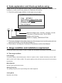
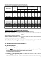
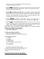
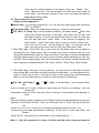
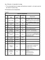
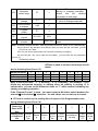
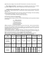
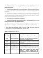
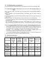
0
User Manual
Contents
Safety Clauses
1. The general of QST-A Series Soft Starter
1.1 The main function
1.2 The main characteristics
2. Code explanation and Check-up before using
3. Usage conditions and Installation directions
3.1 The Usage condition of Soft Starter
3.2 The Installation directions
4. The Connection and External terminal
4.1 The basic wiring diagram of Soft Starter
4.2 The directions of external terminal
4.3 The main circuit connection diagram of Soft Starter
4.4 The communication interface and its directions
5. The Control panel and its operation
5.1 The operation of Keyboard
5.2 Parameter set and its directions
5.3 The functions set of automatic re-startup
5.4 Help and its directions
6. Protection Functions and directions
6.1 Protection functions and theirs parameter
6.2 The directions of protection class
7. Test run and application
7.1 Test run in electricity
7.2 Starting modes and theirs application
7.2.1 Ramp voltage to start
7.2.2 Current-limit to start
7.2.3 Torque control to start
7.2.4 Ramp current to start
7.2.5 Double closed loop starting mode
7.3 Stopping modes and application
7.3.1 Soft stop mode
7.3.2 Free stop mode
7.4 Application example
1
Safety Clauses
In the process of using the soft starter, please note the following Safety Clauses
!Please check this user manual carefully before using the
product
!Only specialist is allowed to install the product
!To be sure that the motor is correctly matched with the soft
starter
!It is forbid to connect capacitors to the output terminals (U V
W)
!Please seal the terminals with insulation glue after finishing
connecting them
!The soft starter and its enclosures must be fixedly earthed
!During maintenance and repair , the input power supply must
be
off.
2
1. The General of QST-A Soft Starter
QST-A series Soft Starter is new type start-up equipment which integrates electric force
and electron techniques, computer technique and modern control theory. It is the new
generation product to replace the conventional Star-delta Starter, Self-coupling
voltage-drop Starter and Magnetic control voltage-drop Starter.
1.1 The main function
This Motor Soft Starter can reduce the starting current of Motor and the power-distribution
capacity to Motor effectively, so it could save the cost.
It can reduce the starting stress of motor and other loading equipment so that lengthen
their service life.
The function of soft stopping can solve effectively the surging problem of inertia system
when stopping. The conventional motor starting equipments can not realize it.
The perfect and reliable protection features , can give the effective protection to the
operator's safety as well as the motor and matched equipments.
The application of intelligent and network technique make the QST-A type Soft Starter
meet the high –speed development of Electrical force automated technique effectively.
1.2 The main characteristics
Perfect design
Pretty external shape and structure, perfect and unique functions, simple and reliable operation, every
technological is made in the best design.
Reliable and high-grade quality
This product is designed according to the computer analog test, has the best electromagnetic
compatibility . It is proved high quality by the high-temperature aging test and jigging test which down
before the products out of factory.
Complete and perfect protection functions
Such as offset voltage protection, failure voltage protection, over voltage protection, Motor overheat or
starting time over long protection, input or output failure phase and three-phase unbalanced protection,
over current, over load and short current protection.
Having the decision-making intellectual property of the product
Including exterior designing patent, decision-making software copyright, the starting and protection
techniques of Motor, and the technology of detecting and debugging.
The best service
The reliable function and quality is the basic of the best service. Even more, we can supply the special
designs and functions of product matched to your need.
3
2. Code explanation and Check-up before using
Please check up the products before using. If some problems happened, please do not
hesitate to contact us with any request for additional information.
※ Check the product type whether it is the right one you want
QST-A series Motor Soft Starter
Code
QST-055-3
Input voltage 3-phase AC380V 60Hz
Matched motor 55KW
Ex-factory code
Date of produce
QST -- A—
Matched voltage class: 3:AC380V, 4:AC480V, 6: AC660
The power of matched motor: 055 is 55KW
Design code A series
Name of company: QIROD ELECTRIC
※ Check any damage to the product because of the transport such as the spare parts are
apart from the body or the shell be damage etc.
※ Check others, including the Certificate of Soundness, and the User Manual .
3. Usage condition and installation requirement
It is a strict rule for the users to use or install the soft starter according to the requirement.
3.1 The usage condition
Power Supply
City power supply, self-provided power, diesel oil dynamic motor, 3-phase alternating current 380V,
480V or 660V ±10%, 50Hz or 60Hz. The power capacity to the soft start must meet the motor starting
requirement.
Motor Matched
Squirrel case asynchronous motor.
Starting Frequency
The starting frequency is set up according to the load equipment.
Cooling Mode
Naturally wind cooling
4
Protective Grade:IP20
Environment Conditions
When altitude is less than 2000m, the temperature of the environment should be between –25 ℃~40 ℃,
relative humidity should be less than 90%, no vapor, no flammable, volatile, no corrosive gas. No
electric dirt, indoor installation, ventilated, vibration is less that 0.5 G.
Note: We can manufacture other type’s soft starter which is used in special conditions,
such as explosion-proof type soft starter, low-temperature type soft starter, or high-voltage
type soft starter.
3.2 The installation requirement
※ The direction and distance of installation: In order to make sure that the soft starter be
in good draft and heat dissipation, please install the product in vertical direction, and be
sure the space is enough for the product.
(See the following diagram 3.1 and 3.2)
※ If the soft starter is installed in a box, please note that the draft is very good , as well as
the above notes .
(See the following diagram 3.3)
3.3 QST Dimensions
Outline dimensions and installation dimensions of 5.5KW-55KW
The rated
Specifications
power of
Outline dimensions(mm)
Installation
NW
dimensions(mm)
(kg)
motor
(KW)
W1
H1
D
W2
H2
d
QST-A-5.5-3
5.5
147
277
168
132
255
M6
<3.5
QST-A-7.5-3
7.5
147
277
168
132
255
M6
<3.5
QST-A-011-3
11
147
277
168
132
255
M6
<3.5
QST-A-015-3
15
147
277
168
132
255
M6
<3.5
QST-A-18.5-3
18.5
147
277
168
132
255
M6
<3.5
QST-A-022-3
22
147
277
168
132
255
M6
<3.5
QST-A-030-3
30
147
277
168
132
255
M6
<3.5
QST-A-037-3
37
147
277
168
132
255
M6
<3.5
QST-A-045-3
45
147
277
168
132
255
M6
<3.5
QST-A-055-3
55
147
277
168
132
255
M6
<3.5
Note: The rated power of motor in the above form is the maximum rated value. Generally speaking,
5
the values of matched motor should not be more than this value.
Outline dimensions and installation dimensions of 75KW-560KW
Specifications
The rated
External outline
Installation
power of
dimensions(mm)
dimensions(mm)
NW
motor
(kg)
(KW)
W1
H1
D
W2
H2
d
QST-A-075-3
75
260
530
200
196
380
M8
<20
QST-A-090-3
90
260
530
200
196
380
M8
<20
QST-A-115-3
115
260
530
200
196
380
M8
<20
QST-A-132-3
132
260
530
200
196
380
M8
<20
QST-A-168-3
160
260
530
200
196
380
M8
<20
QST-A-185-3
185
260
530
200
196
380
M8
<20
QST-A-200-3
200
260
530
200
196
380
M8
<20
QST-A-250-3
250
290
560
200
260
410
M8
<23
QST-A-280-3
280
290
560
200
260
410
M8
<23
QST-A-320-3
320
290
560
200
260
410
M8
<23
QST-A-400-3
400
400
590
200
330
525
M8
<26
QST-A-450-3
450
400
590
200
330
525
M8
<26
QST-A-500-3
500
400
660
200
370
550
M8
<26
QST-A-560-3
560
400
660
200
370
550
M8
<26
4.Connection and External terminal
The QST-A Soft Starter has three types of connection , as following
Main circuit connection , it contains the wiring of 3-phase source input , the output to
motor ,
and the pass-by contactor connection .
External terminal connection , that is the wire comes from twelve external terminals
which
including control signal and analogue output signal .
Communication connection , there are two communication interfaces , those are RJ-45
standard web line socket and DB6 socket which are connected to computer .
4.1 The diagram connection (see the diagram 4.1)
4.2 The external terminal
Please see the diagram 4.2
※ Terminal ① ② are pass-by output , are used to control the pass-by contactor .They
are normal open contacts and are closed when finishing starting .
The contact capacity is AC250V/5A
※ Terminal ③ ④ are time-delay output , the delay time is set by F4 Key , and the
output time is set by FE Key . They are normal open contacts and are closed when
6
finishing output. Please see the detailed information at page 15.
The contact capacity is AC250V/5A
※ Terminal ⑤ ⑥ are fault output , they will be closed when there are any fault matters
happened to the soft starter or loose electricity , while at normal case they are open .
The contact capacity is AC250V/0.3A
※ Terminal ⑦ are Instantaneous stop input , this terminal must be connected with
terminal ⑩ when the starter works normally . But if these two terminals are both open,
the soft starter will stop, and at this time the starter is at the state of fault protection.
Terminal ⑦ can be controlled by the output contact of external protection dives , and it
is useless when the F12 Key is set as 0(basic protection ).
※ Terminal ⑧ ⑨ ⑩ are start-up or stop input . There are two optional ways of
connections: 3-wire connection or 2-wire connection. Please see the diagram 4.3
※ Terminal ⑾ ⑿ are DC 0-20mA analogue output , they show the current value of
motor when real-time working . 20mA is full-scale value and is four times than the rated
current of nominal power of soft starter, while, we can contact a 0-20mA DC current
meter to check. The Max value of output load resistance is 300Ω
Note: Please make sure that the external terminals are in right connection,
otherwise , the product may be damaged .
4.3 The diagram of Main circuit connection
Please see the diagram 4.4
4.4 The communication interfaces
RJ-45 is the standard web line socket
DB9 socket has RS485 and RS232 interfaces inside
Please see the diagram 4.5
① is RS485+
⑥ is RS485② is RS232 output
③ is RS232 input
④ is+5V output (limit-current is 50mA)
⑤ is earthed GND
⑦⑧⑨ are empty
The user can choose the following software
1. Computer collector distribution control communication software
2. Device Net interface card and communication software
3. Device Net / Mod bus / Profibus gateways
4. Others
5.Control Panel and its operation
7
There are five working states of soft starter, those are : Ready , Run ,
Fault , Start and Stop . The control panel will show the current value of
motor when in the process of start or stop, and it will show the set and
help menu at other states .
5.1 The operation of control panel
Please see the diagram 5.1
※ Open state : you should not press the “run” key until the ready-lamp lights and show
“CFC ”or “READY ”.
※ Time-delay state : When the ready-lamp is shining , it means it is time-delay .
※ The “Run” or “Stop” key : In the process of starting , the panel shows “-××××” that
is the value of start-up current . At this time , only “Stop” key is in use , and
the lamps of ready , run and fault are all dark, and you can not come into
the “set” and “help menu ”state . While , in the process of stopping , the
panel shows “_××××” that is the value of start-up current .At this time ,
only “Run” key is in use , and the lamps of ready , run and fault are all
dark , and you can not come into the “set” and “help menu ”state .
※ The “Set” key : Press “Set” key to come into the Set Menu and now the panel is
showing F×: ×××. Please press “Set” key again and Colon is shining, then you can
change the Parameters under the Colon you need. If you want to keep the Parameters
changed, please press “Yes” key, and if you do not want, please pressing the “Set” key
until the Colon stops shining, then the Parameters are former. Having finished the
above operation, please press the “Yes” key to return or “Stop” key to return directly.
※ The “Yes” key : Press the “Yes” key directly , you will come into Help Menu and the
panel shows H×: ×××.When you finish reading the Help Menu , you can press this key
again or “Stop” key to return . This key not only can be used to keep the Parameters
when you set the parameters you need, but also be sued as “Returning” .
※ The “Up” and “Down” ( “ ” “
”) key : In the Set Menu , you can press these
two
keys to choose the Function Code you need when the Colon is not shining , and can
choose the
Parameters under the Colon when the Colon is shining. It is the same as the operation in
Help
Menu.
When the Pass-by-lamp is lighting and the Display Screen shows A××××which means the
operation current value of motor , now , you can press “Up” or “Down” key and the Screen
will
show P×××× or H×××× in turn (P××××means the apparent power of motor ; H××
××means the over-load heat balance coefficient ,if this value is more than 100%, the
Screen
shows “Err06” , that means it is at the state of over-load protection. )
Note: 1. Only the operation is correct, it will be with the voice when pressing the
8
key . Otherwise , the operation is wrong .
※ The control panel uses the super anti-interference material , so it can be used at
the state of 3 meters away .
5.2 Parameters set and explanation
Form 5.1
Set codes explanation
Cod
e
F0
F1
F2
F3
F4
F5
F6
F7
F8
F9
FA
9
Name of the
code
Initial voltage
Soft-starting
time
Soft-stopping
time
Start-up
time-delay
Interlock
time-delay
Start-up limit
current
Max working
current
Under voltage
protection
Over voltage
protection
Starting
modes
Output
protection
class
The range
value
Ex-factory
value
30-70%
30%
2-60S
16S
0-60S
2S
0-999S
0S
0-999S
0S
50-500%
250%
50-200%
100%
40-90%
80%
100-130%
120%
0-5
0-4
Explanation
This range value is useful when
the starting mode is set as ramp
voltage , and if it is limit-current to
start, the Starting voltage is 40%
It is invalid in limit-current starting
mode
If set as “0” , the stop mode is free
stop .
If set as “0” , no time-delay , the
motor be started directly
If set as “0” , no time-delay
This range value is useful when the
starting mode is set as limit-current ,
and if set ramp voltage to start, the
limit-current is 400%
1
0: Limit-current 1:Ramp voltage
2: Torque control + current-limit
3: Torque control +voltage
4: Ramp current
5: Double closed loop
4
0:basic
protection
protection
2:standard protection
3:heavy-load protection
4:the best protection
1:light-load
FB
Operation
control ways
0-7
If set as “7” , that is forbidding
starting or stopping operation ,
please
see
the
detailed
information at next page
0: Forbidding
1: allow to change parameter
1
Parameter
0-1
1
change
Communicatio
FD
0-63
0
n address
Program
FE
0-7
2
output
Soft-start limit
FF
20-100%
80%
current
Rated power
It is the nominal rated current of
Rated value
FP
of motor
motor
Note : ●F6Max working current , that is the Max current for motor to run continuously.
FC
●If you have no any operation for 2 Minutes after you come into the “set” state , you will
return from “set” state .
●You can not set any parameters in the process of starting or stopping .
●If you press the “Yes” key to open the soft starter , you can make the set parameters
recovery to
Ex-factory values .
●FBitem is used to set the control ways of soft
starter
As the following form (Form 5.3)
0
1
2
3
4
5
6
7
Numerical Value
1
1
0
0
1
1
0
0
Key board
0
1
1
1
1
0
0
0
External control
0
0
0
1
1
1
1
0
Communication
Note: In the above form , “1” is Allowing , “0” is Forbidding . For example , if you
forbid any unexpected stopping or starting when the starting is running or in
maintenance , you can set the Numerical Value as “7” which means Forbidding any
starting or stopping operation .
If the “External Control” is used , you must contact a NC button switch between the
terminal ⑧ and terminal ⑩, otherwise , the soft starter can not start-up the motor .
● FE item is used to set the starting time of output of the Programmable relay
As the following form (Form 5.4)
The
Numerical
0
1
2
Value of FE
item
starting time Sendin
Startin Pass-b
g out
of output of
g
y
the
the
3
4
5
6
7
Sendin
g out
the
Finish
stoppin
g
Instantaneo
us stop
Fault
happe
ns
Finish
re-sta
rt
10
Programmab
le relay
order
of
starting
order of
stoppin
g
.
5.3 Help message and explanation
When the product is not starting or stopping , or not at the “set” state , you can press “Yes”
key and come into Help menu , then press the “Up” or “Down” key to choose the help
message . Please press “Yes” or “Stop” key to return .
Help message Form
Message displayed
Explanation
AC380
That is the 3-phase power voltage is AC 380V
05.5-4
That is the Specification is AC480V, 50Hz, 5.5KW
H1: E05
The fault message Err05 that happened at the last time
∶
∶
H9: E00
It says no fault happened
Uer1.5
It says the software of the product is Ver1.5-6.5
Note : The message H1-----H9 displayed means 9 faults kept that happened lately .
6. Protection Functions and theirs explanation
We make our soft starters have all kinds of protection functions to protect the soft starter
and the motor using. Please choose the correct Protection class and parameters
according to your usage conditions!
6.1 Protection functions and theirs parameters
○ Over-heat protection : when the temperature inside soft starter is up to 80℃±5 ℃,
the starter will be into Over-heat protection , when be down to 55℃, this protection
removes.
○ Input failure-phrase protection : the delayed time<3s
○ Output failure-phrase protection : the delayed time<3s
○ Three-phrase unbalanced protection : the delayed time<3s , when the different
current value among three phrases is more than 50% ±10% , the protection be used .
○ Starting over-current protection : the diagram 6.1 shows the protection time when
the current is more 5 times than the rated working current .
○ Working over-load protection : the starter will be in inverse time thermal protection
on base of the Max working current of motor (Set by F6 Item) . (The diagram 6.1 shows)
○ Power voltage failure protection: the delayed time is separately less than 0.5s or 3s
11
when the power voltage is less than half of limited value or less than the set value
.
○ Over-voltage protection : the delayed time is separately less than 0.5s or 3s when
the power voltage is more than 130% if limited value or more than the set value .
○ Loading short-current protection : when the current is more 10 time than the motor
rated current , it will be short current , and then be in short-current protection , the time is
less than 0.1s .
●The time parameters above is from the time receiving the message to the time sending
out the protection message . They are for reference only.
If you need any other protection functions, please contact with us!
6.2 Protection classes and explanation
According different usage conditions, SZPPR-3000 Soft Starter has five protection classes,
as following:
a.
basic protection
b. light-load protection
c. standard protection
d. heavy-load protection
e. the best protection
●Basic protection includes the protection functions of over-heat , short-current protection
and input failure-phrase protection when starting , but no protection of internal connector
instantaneous-stop. We can set this protection grade when the motor is no need to be
stopped urgently, such as fire pump.
●The light-load protection , standard protection and heavy-load protection all have the
every protection function of soft starter. The difference among them is the time surges of
Motor overload heat-protection. See the diagram of 6.1 and Form 6.1.
●When the motor in the best protection starting , it can be protected most perfectly .
The protection classes and the time of heat protection Form (Form 6.1)
Basic
Heavy-loa
Set
Light-load
Standard
The best
protectio
d
Note
explanation
protection protection
protection
n
protection
Standard
The grade of
of
overload
No
2 grade
10 grade
20 grade
10grade
IEC6094
protection
7
-4-2
The grade of
over-current
No
3 grade
15grade
30 grade
15 grade
protection
The
They are
The time of
multiple
the
overload
to the
3 4 5 3 4 5 3 4 5 3 4 5
typical
dropping
rated
values
current
12
The time
of
dropping
(S)
4.
5
2.
3
1.
5
23
12
.
7.
5
46 23 15 23 12
7.
5
Diagram 6.1
t (S)
The 20th grade
The 10th grade
The second grade
I/Ie
Motor heat protection curve diagram (Heat state)
7. Test Run and Application
Please do some examine before test running as following:
○ If the rated power of Soft Starter is matched with the Motor
○ If the Insulation of Motor is up to the requirement
○ If the Main Circuit Connection of Input or Output is correct
○ If all the screws of terminals are twisted tightly
7.1 Set up electricity to test run
1. As soon as the soft starter is electrify, it displays the words of “ SZPU” or “ READY ” ,
and the Ready-lamp is light , then you can press “Run” key to start .
2. Please come into FP item and input the current parameter according to the rated
current on the label of Motor
13
3. Having started the motor, you should examine whether the running direction of
Motor is correct, or whether runs normally. If not, you can press “Stop” key or cut off the
power to stop running.
4. If the soft starter starts badly, you can check whether the starting mode you choose
is fit for your motor. Please see the detailed explanation at 7.2: the starting mode and
application
5. If the Moment of starting is not strong enough, you can change the starting voltage
(when the starting mode is voltage control) or the limit-current value (when the mode is
current control) to strength the Moment of starting.
6. Do not open the up-cover in case of electricity.
7. If there is any abnormal voice, smoke or taste, is very important for you to cut off
electricity as soon as fast, and check the reasons .
8. When the starter is in electricity or is starting , the Fault-lamp is lighting and screen
displays “ Err××” , at this time , you had better check the Form 7.1 to get the reason .
● Note : When the temperature round is less than –10℃ , the starter should be
preheated for 30 minute with electricity , and then start .
Faults and Solution way (Form 7.1)
The
message
displayed
Err00
Err01
Err02
Err03
Err04
Explanation
The fault is removed
The External
Instantaneous stop
terminal is open
The soft starter is too
hot
The starting time is
over long , that is
longer than 60S
Input phase-failure
Reason and the solution way
Any faults are removed , such as under-voltage ,
over-voltage , over-heat .Now the Ready-lamp is
lighting and you can start the motor
Please connect the External Instantaneous stop
terminal (terminal 7) with the Public terminal
(terminal 10)
The starter is started too frequently ,or the starter
is not matched with the motor
The starting parameter is set wrong , or the load
is over and the power capacity is not enough
Please check whether the Input circuit
connection , Pass-by contactor and the
Controlled silicon is open, or whether the KG wire
is connected well
14
Err05
Output phase-failure
Err06
Three-phase
unbalance
Err07
Starting over current
Err08
Running over load
Err09
Under voltage
Err10
Over voltage
Err11
The parameters are
set wrong
Err12
Load short-circuit
Please check whether the Input circuit connection ,
Pass-by contactor and the Controlled silicon are
closed, or whether the KG wire is connected well
Please check the 3-phase power or the Motor is
normal
The load is over , or the Motor is not matched
with the soft starter
The load is over , or the F6 item is set wrong
Please check the voltage of Input power , or the
F7 item is set wrong
Please check the voltage of Input power , or the
F8 item is set wrong
Please change the parameter correctly , or you
can press the “Yes” key to open the starter again
to recovery the Ex-factory values
The load circuit ,or the Controlled silicon is
short-circuit
The external terminals is not connected
according the 2-wire way
The Connection of
Err13
Automatic Re-start is
wrong
The connection of
The reason is that the circuit of external stop
Err14
external terminal is terminal is open
wrong
Err15
Motor underload
Check the motor spindle and Load Faults
Note: Some faults happened are interrelated, so please check the reasons
completely.
Note: When the motor starts successfully, the pass-by-lamp will be lighting, which
means the pass-by contactor is running. At this time, if the contactor is not closed,
the motor will stop running, so you can check whether the connection to the
pass-by contactor is right.
7.2 The starting mode and application
There are six starting modes for the user to choose according the motor and load
equipments, as the following:
7.2.1 Ramp voltage to start (The F9 item is set as “1”, this starting mode is in use )
Diagram 7.1 shows the Output voltage waveform. In the diagram, the U1 is the initial
voltage value of starting. When starting, if the motor current is not more 400% than the
rated current, the Output voltage of soft starter will up to be U1 , and then the Output
voltage rises gradually till to the height of rated voltage (Ue) . The motor runs steadily in
pace with the rising of voltage , and as soon as the voltage is up to be Ue , the motor runs
to be the rated speed and the pass-by contactor is closed , the starting operation finishes .
15
“t” is the starting time .
Note: It is normal that when the load equipments are light, the starting time is less than
the set time.
This mode generally fits for the occasions where the Motor must be started
smoothly.
7.2.2 Current-limit to start (The F9 item is set as “0”, this starting mode is in use )
Diagram 7.2 is the changing waveform of Motor current. In the diagram, I1 is the starting
limit-current value set. When starting, the output voltage rises quickly till the Motor current
up to I1 value and not beyond this value. The motor runs steadily in pace with the rising of
output voltage , and when the motor runs to be the rated speed , the output current will
have a quick-drop and down to the Motor rated current (Ie value) , then the pass-by
contactor is working , the stating operation finishes .
Note: It is normal that when the load equipments are light or the limit-current value you set
is greater, the Max starting current is less than the limit-current value set.
This mode is often used in the conditions which requires strict limit to the current
when starting.
7.2.3
Torque control to start (The F9 item is set as “2” or “3” , this starting mode is
in use)
Diagrams 7.3 and 7.4 show the output changing waveform under torque control mode.
When the static friction force in the state of heavy load is too stronger to start the motor,
can use
this starting mode . When starting, the motor needs a very high voltage for a limited time to
remove the static friction force of heavy load , then you can use the ramp voltage
mode or limit-current mode to start the motor .
Note: This mode will cause big-current shock to the motor , so if the Ramp voltage
or Limit-current mode can be used , please had better not use the Torque control to
start
7.2.4
Ramp Current to start (The F9 item is set as “4”, this starting mode is in use)
Diagram 7.5 shows the Output current waveform. In the diagram, I1 is the current value
set by F5 item, and T1 is Time value set by F2 item.
This starting mode has very stronger speed-up ability and is suit for the Bipolar Motors,
and it can reduce the starting time.
7.2.5 Double closed loop (Both Ramp Voltage and Limit-current) to start (The F9
item is set as “5”, this starting mode is in use)
This starting mode uses the control mode of Ramp voltage starting and Limit-current
starting
Double Closed Loop circuit, it is a composite starting mode.
The Output voltage waveform is changed as Motor and the load equipments.
16
7.3 The Stopping Mode and application
The soft starter has two stopping modes: Soft-stopping mode and Free-stopping mode.
7.3.1 Soft-stopping Mode (The F2 item is not set as “0”, this stopping mode is in
use)
When using this mode to stop the motor, the supply power to motor will be transferred
from the
Pass-by Contactor to the Controlled Silicon of Soft Starter, and the Output voltage of
starter will
be reduced gradually so that the Running Speed of Motor can be cut down smoothly in
case of the
Mechanical Shock. The Output Ending Voltage is the same as the Initial Voltage.
Soft-stopping Mode can reduce or remove the Surge of the loading equipments such as
the Water Pump.
○You can set the Soft-stopping limit-current value through the FF item to reduce the
Big-current Shock to the Motor when stopping . This limit-current value is a Percentage.
7.3.2 Free-stopping Mode (The F2 item is set as “0”, this stopping mode is in use)
When using this mode to stop the motor, the Soft Starter will cut off the connection to
the Pass-by Contactor and forbid the Controlled Silicon outputting voltage as soon as
receiving the order of stopping. The motor stops gradually because of its Inertia.
Generally, If the Soft-stopping Mode is not necessary, please choose the
Free-stopping mode to length the service life of the soft starter.
○ This mode completely forbids the Instantaneous output , in case the instantaneous
big-current shock to the Motor in special application state.
7.4 Application Instruction
Different load equals to different parameter setting. Please see the Form 7.2 for details.
Ramp
Ramp
Ramp
voltage
Initial
Limit-curren
voltage
The loading
starting
voltage to
stopping
voltage
t to start
time
start
time (S)
(S)
Ball
20
6
60%
4
3.5
Grinding
Equipment
Fan
Centrifugal
Pump
Piston
Compresso
r
Lifting
17
26
4
30%
4
3.5
16
20
40%
4
2.5
16
4
40%
4
3
16
10
60%
4
3.5
Equipment
Stirring
Equipment
Breaker
Screw
Compresso
r
Screw
Flight
conveyor
Light-load
Motor
Traveling
Belt
Heat Pump
16
2
50%
4
3
16
10
50%
4
3.5
16
2
40%
4
3
20
10
40%
4
2
16
2
30%
4
3
20
10
40%
4
2.5
16
20
40%
4
3
The above parameters are only for reference and the exact parameter setting
probably is different according to site application request. Any question or doubt,
please feel free to contact the manufacturer.
18
Shanghai QIROD Electric Science & Technology Co., Ltd.
Add: No. 339 Songchun Road, Qingpu District, Shanghai 201700, P.R.China.
Tel: 0086-21-6975 1370 Fax: 0086-21-6975 8387
E-mail: [email protected]
www.QIROD.com (CN)
www.ACdrivemaker.com (EN)
Version 2014. B
Notice: Please contact us for latest product information. We don’t separately inform you of any change due to
product improvement. All rights are reserved by QIROD.
19