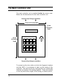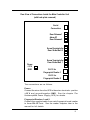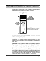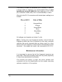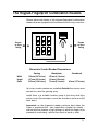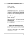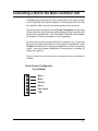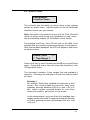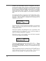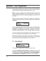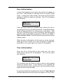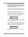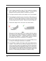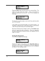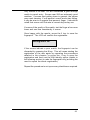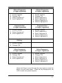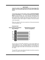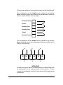
1
GateKeeper Biometric
Door Entr
Entryy Controller
Installation & User Manual
for use with
a ) Fing
er print R
eader
Finger
Reader
b ) Ke ypad and Fing
Finger
er print
reader combination
Version 1.7 October 2003
COPYRIGHT
Copyright 2002 © Ringdale UK Ltd. All rights reserved. No part of this
publication may be reproduced, transmitted, transcribed, stored in a
retrieval system, or translated into any language or any computer
language, in any form or by any third party, without prior
permission of Ringdale UK Limited.
DISCLAIMER
Ringdale UK Ltd. reserves the right to revise this publication and to make
changes from time to time to the contents hereof without obligation to notify
any person or organisation of such revision or changes. Ringdale UK Ltd.
has endeavoured to ensure that the information in this publication is
correct, but will not accept liability for any error or omission.
TRADEMARKS
All trademarks are hereby acknowledged.
Part No: 62 - 14640000
Contents
Introduction
5
Important Information
6
Please read this before attempting installation
Typical Set-Up for the GateKeeper Biometric
Access Controller
7
The Main Controller Unit
8
The Fingerprint Readers
(for Fingerprint Only Versions)
11
The Keypad-Fingerprint Combination Readers
13
Connecting a Door Strike to
the Main Controller Unit
16
Connecting a Bolt to the Main Controller Unit
17
The Uninterruptible Power Supply (UPS)
18
Additional Connections
21
Operation - The Controller Unit Menu
Language Quick Change
Important Authorization Code MIN Information
First Stage Menu Options in Detail
1 - History
2 - Status
4 - Configuration
4.1 - Change Master Identification Number (MIN)
4.2 - Set Time and Date
4.3 - Set Lock Open Time
4.4 - Language Selection
4.5 - Set Access Time Ranges
4.6 - Change Lock Configuration
5 - Communications
6 - Diagnostics
22
25
25
26
26
27
29
30
31
31
32
33
35
37
38
3
Operation - User Registration
3.1 - Registering a New Identity
Door Authorization
Time Authorization
Assigning a PIN (combination reader only)
Registering a Fingerprint
Testing the Fingerprint
3.2 - Editing an Identity
Changing Access Options and Security Levels
3.3 - Deleting an Identity
40
40
43
43
44
45
48
50
52
53
Using the Controller Without an External Reader 54
Relay Board Option
4
56
Introduction
The Ringdale GateKeeper Biometric Door Entry Controller
provides an effective security package for managing up to two
doors using the latest technology, doing away with the need for
conventional keys. It is ideally suited to residential use.
Two door strikes or bolts are supplied together with two
biometric fingerprint readers (or Keypad-Fingerprint
combination readers) that are installed Outside the secure
area. Once a user has been registered, by presenting their
finger (and/or a PIN if this version is required) to the outside
reader, access can be gained through the door.
User registration is performed using the main controller unit
that is installed Inside the secure area. This has a Liquid
Crystal Display (LCD), its own fingerprint reader and a built in
keypad. As an added security feature a separate Master
Identification Number (known as the MIN) is set to restrict
access to the controller unit. Up to 15 users can be registered
with the controller at any one time for the fingerprint only version.
For the combined Keypad-Fingerprint reader, up to 600
identities can be stored.
The controller provides a host of options to tailor the system to
specific requirements, such as the ability to register users to
use one door only, and to set time restrictions for when access
will be granted.
The package provides an Uninterruptible Power Supply (UPS)
that in normal operation will trickle charge a lead acid battery
(not supplied) to ensure that in the event of a power failure the
battery continues supplying power (the length of time the backup will last depends on the size of battery that is used).
No additional hardware or PC connection is required to operate
the package, ensuring the product maintains an independent
and self-contained position within a security set-up, making it
ideal for residential and small locations.
This guide is designed to provide quick instructions for the
installation of the package, together with details on how to
configure and use the system once installed.
5
Important Information
Please read this information before attempting any
installation procedures.
WARNING
Only connect the Uninterruptible Power Supply (UPS) to the
mains electricity supply after all other hardware installation
has been completed. Ensure that any time the UPS, main
controller unit or biometric readers are opened that the
mains electricity supply is safely isolated.
Do not remove the earthing nuts fastened to the side and
door of the UPS - these are marked with red sealant.
If testing or using the UPS without a battery back-up fitted,
ensure that the connectors at the end of the battery leads
are insulated.
Location Advice
When installing the GateKeepersystem, please take into
account the length of cable required to connect the main
controller unit to the door strike/bolt, biometric reader, and
UPS.
Note
If no external readers are attached to the controller unit,
access capability will default to the fingerprint reader on
the unit itself - see the chapter Using the Controller Without
an External Reader for more details on this.
6
Typical Set-up for the
GateKeeper Biometric Access Controller
Uninterruptible Power Supply (UPS)
Mains
Power
Main
Controller
Unit
Battery
123
123
123
Door 1
12
12
12
12
Door
Strike 1
Optional
Door Release
Button and/or
Tamper Switch
Connecting to
Alarm System
12
12
12
12
12
Fingerprint
Reader 1
Door 2
12
12
12
12
Door
Strike 2
12
12
12
12
12
Fingerprint
Reader 2
7
The Main Controller Unit
The main controller unit is installed Inside the secure area.
Below are the dimensions for the main controller unit.
Screws to Open Casing Located Here
135 mm (5.31 Inches) Wide
40 mm
(1.57 Inches)
Depth
170 mm
(6.69 Inches)
Length
1
2
3
F
4
5
6
E
7
8
9
D
A
0
B
C
Screws to Open Casing Located Here
To connect up the door strikes or bolts, the fingerprint readers
and the UPS, it is necessary to open up the casing of the
controller. This can be done by removing the four screws that
hold the two halves of the casing together. These are located
on the top and bottom edges of the casing, as shown above.
8
Rear View of Connections Inside the Main Controller Unit
(with back plate removed)
Serial
Connection
Door Release 1
Alarm I/P
Door Release 2
Screw Terminals for
Door Strike/Bolt 2
Power
+12 V
GND
Screw Terminals for
Door Strike/Bolt 1
RJ-12 for
Fingerprint Reader 1
RJ-12 for
Fingerprint Reader 2
The connections are as follows:
Power
Connect the wires from the UPS to these two terminals - positive
+12 V and ground/negative GND. See the chapter The
Uninterruptible Power Supply (UPS) for details.
Fingerprint Readers 1 and 2
Connect the supplied cable from each fingerprint/combi reader
to these RJ-12 Ports. See the reader chapters later in the
manual for full details.
9
Note: if using only one fingerprint/combi reader, ensure that
the fingerprint reader port that is selected matches the screw
terminals that are being used for a door strike or bolt (for
example, if a door strike is connected to screw terminals 1, the
reader will need to be connected to RJ-12 1).
Screw Terminals 1 and 2
Connect the wires from the door strikes/bolts to the screw
terminals here. See either the chapters Connecting a Door
Strike to the Main Controller Unit or Connecting a Bolt to the
Main Controller Unit for details.
Additional Screw Terminals
The third set of terminals at the top of the board provide the
ability to connect additional devices to the main controller unit
(for example, if a door release button is required to open the
door from the secure side or a tamper switch needs to be
connected to an alarm system to warn if someone tries to
interfere with the controller unit). See the Additional
Connections chapter for details.
Serial Connection
RJ-12 port for connection of additional devices.
The Back Plate
Depending on how and where the controller unit is to be located,
it might be necessary to feed the cables and wires through the
back plate of the casing before connection to the controller
unit. Two holes are provided - a wide circle in the center of the
back or a slim cutout at the bottom of the plate - use whichever
is most appropriate.
The option is also provided to feed the cables through the
bottom of the casing - the shaped cutout has to be removed to
use this option.
10
The Fingerprint Readers (for Fingerprint Only Versions)
Below are the dimensions for the fingerprint readers that are
supplied with the biometric door entry controller:
40 mm (1.57 Inches)
Wide
30 mm
(1.18 Inches)
Depth (including
finger-shaped lip)
110 mm
(4.33 Inches)
Length
Green LED (fingerprint accepted)
Red LED (fingerprint rejected)
Up to two readers are installed Outside the secure area and
will be used for gaining entry.
Install them in a suitable location close to the doors that they
are to control (for example, one at the front door and one at the
back door).
Important: as the fingerprint reader performs best when the
finger is presented flat - see registration chapter for details ensure that the location is high enough to allow the finger to be
presented comfortably, without the need to bend or twist.
The supplied cable connects to the RJ-12 port on the back of
the fingerprint reader and to the RJ-12 Fingerprint Reader ports
on the back of the main controller unit (the back of the casing of
the controller will need to be removed first - see the previous
chapter for details of this and location of these ports).
11
This cable is suitable for distances up to 4 meters (13 feet). If
a longer cable is required, it is recommended that a 3 pair
twisted pair wiring 24 AWG UL listed ending in a RJ-12 (6pin) connector either side (Cat 5 recommended) is used.
Wiring for the RJ-12 connectors with twisted pair cabling is as
follows:
Pin on RJ-12
Color of Wire
1
Orange/White
2
3
Orange
Green/White
4
5
Blue
Blue/White
6
Green
All voltages and signals are below 5 volts.
Note: if using only one fingerprint reader, ensure that the
fingerprint reader port that is selected on the main controller
matches the screw terminals that are being used for a door
strike or bolt (for example, if a door strike is connected to screw
terminals 1, the reader will need to be connected to RJ-12 1).
Maintenance Information
It is important to ensure that all the fingerprint sensors are
kept clean. Wipe them regularly with a soft, dry cloth (especially
if users have particularly oily hands).
The cleaner the sensor is kept, the more reliable and
consistent will be the identification by the reader, ensuring
optimum operation of the system.
12
The Keypad-Fingerprint Combination Readers
Shown below are details of the keypad-fingerprint combination
readers that are supplied with the biometric door entry controller:
2
3
4
5
6
7
8
9
0
#
Enter
Ringdale
Screws
to Open
Casing
1
Screws
to Open
Casing
Clear
Biometric Combi Reader Dimensions
Casing
Backplate
Width
Height
139 mm (5.47 Inches)
107 mm (4.21 Inches)
155 mm (6.1 Inches)
113 mm (4.5 Inches)
Depth
32.5 mm (1.28 Inches)
7.5 mm (0.3 Inches)
Combined
40 mm (1.57 Inches)
Up to two combi readers are installed Outside the secure area
and will be used for gaining entry.
Install them in a suitable location close to the doors that they
are to control (for example, one at the front door and one at the
back door).
Important: as the fingerprint reader performs best when the
finger is presented flat - see registration chapter for details ensure that the location is high enough to allow the finger to be
presented comfortably, without the need to bend or twist.
13
To connect up the supplied cable to the combi reader, it is
necessary to open up the casing. This can be done by removing
the two screws that hold the casing to the backplate. These
are located on the edge of the front of the casing, as shown
previously. Feed the cable through the backplate and connect
to the RJ-12 port. Replace the backplate.
The other end of the cable connects to the RJ-12 Fingerprint
Reader ports on the back of the main controller unit (the back
of the casing of the controller will need to be removed first - see
the earlier chapter for details of this and location of these ports).
This cable is suitable for distances up to 4 meters (13 feet). If
a longer cable is required it is recommended that a 3 pair
twisted pair wiring 24 AWG UL listed ending in a RJ-12 (6pin) connector either side (Cat 5 recommended) is used.
Wiring for the RJ-12 connectors with twisted pair cabling is as
follows:
Pin on RJ-12
Color of Wire
1
Orange/White
2
3
Orange
Green/White
4
5
Blue
Blue/White
6
Green
All voltages and signals are below 5 volts.
Note: if using only one combi reader, ensure that the fingerprint
reader port that is selected on the main controller matches the
screw terminals that are being used for a door strike or bolt (for
example, if a door strike is connected to screw terminals 1, the
reader will need to be connected to RJ-12 1).
14
The combi reader can provide the following options:
PIN (Personal Identification Number) and Fingerprint access
PIN only access
Fingerprint only access
PIN or Fingerprint access
Important
When a PIN and fingerprint access are being used together
(with the and option listed above), the PIN Must be entered first.
This will allow the controller to search only those fingerprints
associated with the user of that PIN, rather than search through
the entire database to find a match, allowing speedy access.
Keypad Operation
To gain access using a PIN, simply tap in the number and
press the * (Enter) button.
Once a number has been selected, there is a ten second
window in which to press the * button before the selection will
be automatically cleared.
Pressing the # (Clear) button will clear all digits selected, not
just the last digit pressed.
Fingerprint Sensor Maintenance Information
It is important to ensure that all the fingerprint sensors are
kept clean. Wipe them regularly with a soft, dry cloth (especially
if users have particularly oily hands).
The cleaner the sensor is kept, the more reliable and
consistent will be the identification by the reader, ensuring
optimum operation of the system.
15
Connecting a Door Strike to
the Main Controller Unit
The cable required for connecting a door strike to the controller
unit is a 2 wire multi strand 18AWG UL listed cable which
carries 12 Volts.
The wires are connected to the Screw Terminals on the back
of the controller unit (the back of the casing of the controller will
need to be removed first - see The Main Controller Unit chapter
for details of this and location of the terminals).
As two door strikes can be connected to the controller unit,
there are two sets of screw terminals for this purpose
numbered 1 and 2 (Note: the third set of screw terminals are
not for connecting to a door strike - see the chapter Additional
Connections for details of using this option).
Only two of the terminals are required for connection of a door
strike, as shown below:
Screw Terminal Configuration
Top to Bottom
Strike/Lock +
Strike/Lock Not
Used For
Door
Strike
The door strike wires are
connected as follows:
The 2-way terminal block of the
door strike mechanism is
marked with +(plus) and (minus).
Connect a wire from the + (plus)
terminal of the mechanism to the
Strike/lock + connector on the
screw terminal.
Connect a second wire from the
- (minus) terminal of the door
strike mechanism to the Strike/
Lock - connector on the screw
terminal.
16
Connecting a Bolt to the Main Controller Unit
A Ringdale security bolt can be connected to the main control
unit if required (for further details on connecting the bolt see
the specific bolt manual that accompanies the product).
The wires are connected to the Screw Terminals on the back
of the controller unit (the back of the casing of the controller will
need to be removed first - see The Main Controller Unit chapter
for details of this and location of the terminals).
As two bolts can be connected to the controller unit, there are
two sets of screw terminals for this purpose numbered 1 and
2 (Note: the third set of screw terminals are not for connecting
a bolt - see the chapter Additional Connections for details of
using this option).
The six wires from the bolt are connected to the terminals as
follows:
Screw Terminal Configuration
Top to Bottom
Motor +
Motor Bolt Out
Bolt In
Door Closed
COM
17
The Uninterruptible Power Supply (UPS)
WARNING
ENSURE THAT THE MAINS POWER SUPPLY IS ISOLATED BEFORE
ATTEMPTING TO CONNECT THE UPS TO THE MAIN CONTROLLER UNIT
OR FITTING/REMOVING A BATTERY
DO NOT CONNECT TO THE MAINS POWER SUPPLY
UNTIL INSTALLATION IS FINISHED
If testing or using the UPS without a battery back-up fitted,
ensure that the connectors at the end of the battery
leads are insulated.
Connecting the UPS to the Controller Unit
The cable between the CPU and the controller unit is a 2 wire
multi strand 18AWG UL listed cable which carries 12 Volts.
The maximum length is 50 meters (164 feet).
The Positive wire connects to the +12 V terminal on the
controller unit - see The Main Controller Unit chapter to locate
this terminal.
The Negative/Ground wire connects to the GND terminal on
the controller unit (located right next to the above terminal).
To
Controller To
Unit Battery
GND 12V+ - +
Out Out
18
Here is a view of the terminals on the
power supply board of the UPS - these
are located at the bottom right corner of
the circuit board. The board itself is
located at the top of the UPS box:
The Positive wire connects to the 12 V + terminal on the power
supply board of the UPS.
The Negative/Ground wire connects to the GND terminal on
the power supply board of the UPS.
Fitting the Battery into the UPS
Warning
If testing or using the UPS without a battery back-up fitted,
ensure that the connectors at the end of the
battery leads are insulated.
Battery Details
Any sealed lead acid type rechargeable battery of 12V DC with
1.2Ah up to 17 Ah should be suitable up to a maximum size of:
Width: 180 mm (7 Inches)
Depth: 75 mm (2.95 Inches)
Height: 167 mm (6.57 Inches)
The storage capacity of the battery to be used will depend on
your particular requirements. An example of a suitable 1.2 Ah
battery is the YUASA NP1.2-12. An example of a suitable 1.7
Ah battery is the YUASA NP1.7-12i.
Note
Three sets of leads with different connectors will be supplied
with the UPS - use the type that is suitable for the connections
on the battery.
Place the battery in the tray on the bottom of the UPS.
The previous image of the terminals on the power supply
board shows the location of the battery terminals
The + (positive) and - (negative) battery leads fit to the
respective + and - terminals on the battery and on the power
supply board.
19
Connecting the UPS to the Mains Power Supply
The voltage of the power supply to the UPS should be within the
range of 12-15V/1 Amp.
Depending on the local safety regulations, it is recommended
that the UPS be connected to a switchable and/or fused
distribution point with a higher rating than the internal mains
fuse.
Fuse rating for fuse F1 (Mains Fuse) is T1.0 A/250V
Fuse rating for fuse F2 (Battery Fuse) is T3.15 A/125V
Always replace a fuse with one of the same rating.
For safety reasons, the mains electricity transformers are in
the protective casing at the top of the UPS Box.
Do not remove the earth connections from the side and door of
the UPS (these are marked with RED sealant).
Connect the power supply cable from the mains to the socket
on the outside of the left side of the UPS box. Switch the
power on.
Two LEDs on the power supply board display the status of the
mains and battery power as shown below:
LEDs
Red
Green
Mains On Battery On
20
Additional Connections
It is possible to connect additional devices to the controller
unit. If a door release button is required to open the door from
the secure side, or a tamper switch needs to be connected to
an alarm system to warn if someone tries to interfere with the
controller unit, both options can be fitted.
The wires are connected to the third set of Screw Terminals
on the back of the controller unit (the back of the casing of the
controller will need to be removed first - see The Main Controller
Unit chapter for details of this and location of the terminals).
The third set of screw terminals are those situated uppermost
on the back of the controller unit. Do not use the two lower
sets of screw terminals (these are for use in connecting a
door strike or bolt only).
The cables required for connecting these options are a 2 wire
multi strand 18AWG UL listed cable which carries 12 Volts.
Below are details of the function of each terminal:
Screw Terminal Configuration
Top to Bottom
Ground/ Door Release 1 +
Alarm Ground/ Alarm +
Ground/ Door Release 2 +
Connect a wire from the +
(plus) terminal of the
external device to the
required + connector on
the screw terminal.
Connect a second wire
from the - (minus)
terminal of the external
device to the required connector on the screw
terminal.
21
Operation - The Controller Unit Menu
When the mains power supply is turned on, the LCD screen
on the controller unit will come to life. The controller will run
through some diagnostics and then beep twice when ready.
The screen will display the following:
Ready
Menu(A)
12:00
am
This is the default status of the LCD screen, referred to as
Normal Operations. The time will be displayed on the right
side of the screen. The LCD screen and keypad on the
controller unit are used to access all the features for the system,
including the registration of users. This is done through the
menu system.
Below is a table displaying the menu structure. Note: the
menu system will vary slightly depending on whether the
combination Keypad-Fingerprint reader or fingerprint only
version of the reader is being used.
Biometric Access Controller LCD Menu
22
First Stage Menu
Second Stage Menu/Option
1
History
List of Events
2
Status
Time and Date
Identities
Fingerprints
Free Prints (combination reader only)
Free Prints (if fingerprint is being used alone
or first)
SFPR (s)
Firmware Version Number
Firmware Date
Combination Reader Firmware Version
Number (combination reader only)
3
Enroll
1
2
3
4
Configuration
1
2
3
4
5
6
0
New Identity (sub-menu on combi only)
PIN and Fingerprint
PIN Only
Fingerprint Only
PIN or Fingerprint
Edit Identity
Sub-menu is option dependent
Delete Identity
Change MIN (Master Identification
Number)
Time and Date
Lock Open Time
Language Selection
Access Times
Lock Configuration
Normal Operations
5
Communications
For Connection of External Device
6
Diagnostics
1
2
3
4
5
6
7
0
0
RAM Test
Keypad Test
LCD Test
Fingerprint Reader Tests
1 Fingerprint reader 1
2 Fingerprint reader 2
3 Controller unit reader
Lock Tests
1 Door strike/bolt 1
2 Door strike/bolt 2
Serial Port Loopback
System Reset
Normal Operations
Normal Operations
Following are details of how to use the menu system:
23
Note: ensure the LCD display is at Normal Operations before
starting.
The first stage menu can be accessed in two ways, either:
(a) Press the number on the keypad for the first stage menu
required (1 - 6). This is suitable when familiar with the menu
system and the user knows exactly where they want to go.
Or
(b) Use the scrolling feature to run through the first stage menu.
This method is more suitable when first using the system as
it enables the user to browse for what they are looking for.
The scrolling feature is activated by pressing the A button on
the keypad - as a reminder this is indicated on the LCD when
in Normal Operations mode.
Menu
1 History
< (B) (C) >
Above is an example of the screen that will be displayed. This
is the first menu option.
To access that option press the number on the keypad - in
this case 1. To scroll through the menu options, use the C key
to move forward and the B key to move backward.
Scrolling through to the end will give the option 0. Select the 0
key to return to Normal Operations.
Important
The controller unit will always return to the Normal Operations
mode if no key is pressed for 30 seconds (this is to ensure
that it is not possible to get locked out of the secure area).
24
Language Quick-Change
To change the language displayed on the LCD, press 4 4 on
the key pad. English is the default Language. The
alternative offered is Spanish.
Important Master Identification Number (MIN)
Information
For security reasons, access to the sensitive information and
configuration features of the controller unit is restricted. An
authorization code in the form of a Master Identification Number
(MIN) is used for this.
By default the authorization code is 1234.
It is highly recommended that this is changed during the
first set-up procedure to a number known only by yourself.
Do not under any circumstances divulge your
authorization code to anybody else. This can
compromise the security of the system.
The MIN is for use with the controller unit only, not for any
combi readers located outside the secure area, and the
number is only for gaining access to certain parts of the
controller’s menu - it should not be confused with the
separate Personal Identification Numbers (PINs) issued to
each user to allow them access when using a combi reader.
Press 4 1 on the keypad to quick-change the MIN to another
four digit number. Full details on changing the MIN can be
found later in this chapter in the section First Stage Menu
Options in Detail, 4 - Configuration.
If an invalid MIN is entered on the keypad, an intermittent alarm
will sound on the controller.
25
First Stage Menu Options in Detail
The operation of the second stage menu will vary depending
on the option selected. Following are details for each of the
first stage options (except option 3 - Enroll. This is covered in
a separate chapter following):
Note: where differences in the menu exist between the
fingerprint only and keypad-fingerprint combi readers this will
be indicated.
1 - History
This option gives the ability to scroll through a list of up to the
last 200 events, viewed in reverse chronological order. Press
the 1 key on the keypad to enter the list. The LCD will display
the following:
History
<(B) (C)>
0 Normal Ops
Press the C key to scroll forward and the B key to scroll back
again. Pressing 0 at any time will return the controller to Normal
Operations
Below is a typical example of the information that will be
displayed on the screen for each recorded event. Note: this
will vary depending on the access options being used - though
the information and format will be essentially the same. This
example shows an entry that has been granted from a
fingerprint only:
Ident: 002 (177)
1 07:29pm JUN 27
Details of the information displayed in the event example
shown above is as follows:
The person who has been registered with fingerprint ID 002
touched the sensor on door 1 at 07:29:pm on June 27th and
was allowed to enter.
26
The fingerprint match score in the parentheses helps to keep
track of how well a fingerprint is matching. Only scores of at
least 116 are considered a good enough match to permit
entry. Scores near 200 are extremely good matches. If scores
start getting lower in general, the sensor may need cleaning.
If one person’s score levels start falling, it may be wise to reregister that person’s finger. It should be noted that scores
will fluctuate in normal day to day use (for more details on
fingerprints see the following chapter).
If a registered user tries to gain access through a door they do
not have rights to, the attempt will be listed in the History with
Refused Door. If a user has time restrictions and tries to gain
access, the attempt will be listed in History as Refused Time.
2 - Status
Menu
2 Status
< (B) (C) >
This option allows status information to be viewed. Pressing
the 2 key on the keypad will display the first item, which is the
Time and Date. An example is shown below:
Status (C) > 03:21
Fri 28 - JUN - 02 am
Note: the day of the week will be automatically detected from
the date and displayed here.
Move through the list of other options by pressing the C key.
Pressing any other key will return the display to Normal
Operations.
The next item in the list is Identities, an example of which is
shown below:
Status (C) >
Identities: 12
This displays the number of users (or identities) that have
been registered on the controller unit. In the example here, 12
27
people are registered to use the system (a maximum of 600
identities are available for the combi reader).
The next item is similar to the above, but displays how many
Fingerprints are registered on the controller unit (up to 600
fingerprints can be stored depending on the access options
that are being used - see the following chapter for full details
on this).
For the keypad-fingerprint combination reader only there
will be a Free Prints display, which will show the number of
fingerprints that can still be stored on the controller (please
note the information below as this maximum can only be used
in certain circumstances).
The next item is shown here:
Status (C) >
FP 1st, Free: 11
FP 1st Free displays the number of fingerprints that are left
free on the controller if a fingerprint first or fingerprint only
access option is being used.
Important
When a PIN and fingerprint access are being used together
the PIN Must be entered first. This will allow the controller to
search only those fingerprints associated with the user of that
PIN, rather than searching through the entire database to find
a match, allowing speedy access. If a large amount of
fingerprints are registered and the controller unit has to search
them all, this could take a considerable amount of time.
If fingerprint only readers are being used, or if the Fingerprint
Only or PIN or Fingerprint access options have been chosen
on the combi reader, it is recommended that no more than 15
fingerprints be registered. Without a PIN to identify the
registered user first, the controller unit has to search all stored
fingerprints to find a match. The more fingerprints stored, the
longer this will take, which could lead to a delay in gaining access.
For full details on access options and fingerprint storage, see
the following chapter.
28
Press the C key to move on to the next item. SFPR(s) will
display which fingerprint reader ports on the controller unit
have a reader actually attached to them. An example is shown
here:
Status (C) >
SFPR(s):
1
2
In this example both reader ports have a reader attached to
them. If only one reader was attached, there would be a symbol for the empty port and only the used port number would
be displayed.
The final items displayed will be the Firmware Version
Number and the Date of the Firmware.
For the keypad-fingerprint combination reader only there
will be a final item - the Firmware Version Number of the
combi reader/s (in normal circumstances the firmware version
will be the same for both readers that are attached to the
controller, so only one version number will be displayed - by
default this will be from the reader attached to port 2. To view
the firmware version number of port 1 specifically, unplug the
reader from port 2 and enter 6 and 7 on the keypad of the
controller unit. Then return to the Status menu and the version
number for the reader in port 1 will be displayed).
3 - Enroll
For details of this option see the separate chapter following
this one - Operation - User Registration.
4 - Configuration
Menu
< (B) (C) >
4 Configuration
This option allows the set-up or changing of the settings for
the system and uses a second stage menu. Pressing the 4
key will enter the second stage menu. The configurations
that can be altered are detailed here in their second stage
menu order.
29
To scroll through the second stage menu options, use the C
key to move forward and the B key to move backward.
Scrolling through to the end will give the option 0. Select the 0
key to return to Normal Operations (Note: this can be pressed
any time within this menu system to return there).
4.1 - Change MIN (Master Identification Number)
Configuration
1 Change MIN
Use this option to change the Master Identification Number MIN - highly recommended when using the system for the
first time. This is the authorization code to restrict access to
the controller. Press 1 on the keypad and the LCD will ask for
the existing MIN (this is to prevent unauthorized people from
being able to alter the code). If using the option for the first
time, the MIN will be the factory default setting of 1234.
The MIN is for use with the controller unit only, not for any
combi readers located outside the secure area, and the
number is only for gaining access to certain parts of the
controller’s menu - it should not be confused with the
separate PINs issued to each user to allow them access
when using a combi reader.
Take care with the MIN. If it falls into the wrong hands,
this can compromise the security of the system.
Once the existing MIN has been accepted, the LCD will ask
for the new MIN to be entered (4 digits) as shown below:
Old MIN: New MIN: _
Once the new MIN has been entered, the LCD will ask for the
new MIN to be confirmed. Re-enter the new MIN, and the LCD
will display the following:
Saving New MIN
30
4.2 - Time and Date
Configuration
2 Time and Date
Use this option to change/set the time and date. Press 2 on
the keypad and the LCD will display the following:
F+/E<(B) (C)>
00:00a 01 - JAN - 00
Use B and C on the keypad to move across the screen. Use F
and E on the keypad to set the correct time and date. AM time
is represented by a, and PM time is represented by p.
When finished press the 0 key twice to return to Normal
Operations.
4.3 - Lock Open Time
Configuration
3 Lock Open Time
Use this option to change the Lock Open Time (the length of
time the lock is opened when access is granted, before the
lock will automatically shut again). The default setting is five
seconds. This can be changed from 1 second to 9.9 seconds
in increments of .10 of a second. Press 3 on the keypad, and
the LCD will display the following:
Lock Open Time
F+/E- 5.0 Secs
Use the F and E keys to set the open time as required. F
moves the time forward and E moves the time backward.
When set as required, press the 0 key to save the new setting.
Press 0 again to return to Normal Operations
31
Note
The Lock Open Time can also be set so that it does not
automatically shut. In this configuration, the lock will be
opened when a valid identity is recognised, and the lock will
remain open until a second valid identity is recognised again
at the door.
The lock is set to operate in this way by adjusting the value
downward below the 1.0 second minimum in the configuration
menu. Set the Lock Open Time to 0.0 seconds.
Important: it is recommended that only Ringdale door strikes
or bolts are used with this setting to avoid long periods of
maintaining an output voltage to a lock.
4.4 - Language Selection
Use this option to change the language of the LCD. The
default setting for the screen is English. The alternative option
is Spanish.
If scrolling through the second stage menu, the language
selection option will be displayed as follows:
Configuration
4 Español
Pressing 4 on the keypad will automatically switch the
language.
The quick way to change the language is to enter 44 into the
keypad. The LCD language will be changed straight away.
32
4.5 - Access Times
Configuration
5 Access Times
The controller has the ability to restrict users to only gaining
access at certain times. Use this option to set the times that
restricted users can gain access.
Note: this option only needs to be set up if the Time Checked
option is being used during the registration of new users see the following chapter for full details on this facility.
On pressing the 5 key, the LCD will ask for the MIN to be
entered (this is to prevent unauthorized access to this feature).
After this has been accepted, the LCD will display a sub-menu
as shown below:
Access Times
<>
1 Time Range 1
Press the C key to scroll forward and the B key to scroll back
again. Pressing 0 at any time will return the controller to the
Configuration menu.
The sub-menu contains 4 time ranges that are available if
required. Following are examples of how this feature would
be used:
Example 1
Mr. and Mrs. Smith have installed the controller in their
house. Mrs. Jones cleans the house for them every
weekday morning between 9:00 a.m. and 1:00 p.m.
Mrs. Jones is given restricted access for only those
times she needs to get access to the house.
In this circumstance, only one of the four available time
ranges needs to be used. A range can be set for Monday
to Friday, granting access only between 8:45 a.m. and
1:05 p.m.
33
Example 2
Mr. and Mrs. Smith have installed the controller in their
house. Mrs. Jones cleans the house for them three
days a week, on a Monday, Wednesday and Friday
between 9:00 a.m. and 1:00 p.m. Mrs. Jones is given
restricted access for only those times she needs to
get access to the house.
In this circumstance, three of the four available time
ranges would be used. A separate range would be set
up for each of the three days, granting access only
between 8:45 a.m. and 1:05 p.m.
Use the following procedure to set up a time range:
1
Select the first available time range from the sub-menu (when
setting up for the first time this will be 1) by selecting the
number on the keypad. The day range will be displayed first
as shown below:
F/E
Mon- > Fri
2
<(B) (C) >
Set the day range required. Use the B key to move forward
and the C key to move backward between the From and To
choices.
Use the F and E keys to select the days required. Pressing the
C key when the cursor is located in the To field will display the
time range, as shown below:
F/E
<(B) (C) >
08:45a > 01:05p
3
34
Using the same method, set the From and To times that will
give access to the user. The hours and minutes are set
separately for both and a signifies am, p signifies pm.
Important Notes on Time Ranges
a) A time range that has the same From and To times is
considered empty.
b) Day ranges are inclusive:
Monday > Friday covers five days
Saturday > Friday covers seven days
Monday > Monday covers Monday only
c) A time range doesn’t include the actual To time. For
example, if the To time is 1:05 pm access will be granted
until the end of 1:04 but not for 1:05 itself (unless another
time range dictates otherwise).
d) If more than one time range is being used, they are allowed
to overlap each other.
e) The controller automatically determines the day of the week
according to the current date settings.
f) Time ranges are not lost if the controller is rebooted or
reset.
4
When the time range is set as required, press the C key once
more. The LCD will inform that the configuration has been
saved. Repeat procedure to set up as many time ranges as
required.
4.6 - Lock Configuration
Configuration
6 Lock Config.
Use this option to change the configuration for a door strike or
bolt that is being connected to the controller unit.
By default, the controller is set up to work with a standard
power to open door strike (suitable for the majority of
installations) and, in this situation, this option will not need to
be used.
35
However, the GateKeeper controller is designed to be able to
function with a large variety of devices, and this option provides
the facility to change the settings on the controller to match
the device that is connected (note: some devices - for example
those requiring 24 volts to operate - will require the optional
relay board, see the last chapter of the manual for details on
this).
On pressing the 5 key to enter the Lock Configuration option,
the LCD will ask for the MIN before the options will become
available. After the MIN is accepted the following will be
displayed on the LCD:
Lock Config.
1 Lock
#1
<>
Press the C key to scroll forward and the B key to scroll back
again. Pressing 0 at any time will return the controller to the
Configuration menu.
There are 3 options, the settings for Lock 1 (as shown in the
example above), the settings for Lock 2 and the chance to
return to Normal Operations if required.
Select the number on the keypad for the lock that is required.
The LCD will display the following:
F/E
<(B) (C) >
STR: STD: PTO: There are 4 settings shown here (STR, STD, PTO, -). These
are the default settings. Use the B key to move forward
through the settings and the C key to move backward through
the settings.
When the setting required is selected use the F and E keys to
switch between the options for each setting. There are two
options for each setting. The options are as follows:
36
Option 1
Option 2
Option 1
Option 2
Setting 1
Setting 2
STR (Door Strike)
BLT (Bolt)
STD (Standard Lock Type)
PLS (Pulse Lock Type)
Setting 3
Setting 4
PTO (Power to Open)
PTC (Power to Close)
- (No Side Pressure Pulse)
SPP (Side Pressure Pulse)
See the specifications of the lock/bolt device for details of the
options that will be required.
When the options required have been selected, press the 0
key to save the changes. The LCD will confirm that the new
configuration is saved, as shown below:
Saving Config.
Once set up, the configuration will not need to be changed
again unless the type of door strike or bolt is changed.
5 - Communications
Menu
< (B) (C) >
5 Communications
This option is for use when an external device (for example, a
PC) is connected to the controller unit using the serial port this is located on the back of the controller unit (the back of the
casing of the controller will need to be removed first - see The
Main Controller Unit chapter for details of this and location of
the port). Activating this option will allow the controller unit to
communicate with the external device.
Note: the MIN will need to be entered to gain access to this
option. Should this option be required, contact Ringdale
Technical Support for more details. It is recommended only
for advanced PC users.
37
6 - Diagnostics
Menu
< (B) (C) >
6 Diagnostics
This option provides the ability to run tests on each part of the
system to ensure that they are functioning correctly. It operates
using a second stage menu and at times a third stage menu
that work in the same manner as the first stage menu. Press
the 6 key to enter the second stage menu.
Important Note
In normal operation, the Diagnostics menu can be accessed
without entering the MIN, but if the controller has no external
fingerprint or combi readers attached, the access capability
defaults to the fingerprint reader on the controller itself.
Because the Diagnostics menu provides the ability to test the
locks (therefore the ability to open the doors), the MIN will be
required to gain entry to these menu options in this situation.
This is necessary to maintain the security of the system.
The options available are detailed here in their second stage
menu order.
To scroll through the second stage menu options use the C
key to move forward and the B key to move backward.
Scrolling through to the end will give the option 0. Select the 0
key to return to Normal Operations (Note: this can be pressed
any time within this menu system to return there).
6.1 RAM Test - Press 1 to run a test to ensure that the Random
Access Memory (RAM) is functioning correctly.
6.2 Keypad Test - Press 2 to run a test of the keypad. The
LCD will permit each key to be displayed as it is pressed to
ensure that all the keys are functioning correctly. Press the F
key three times to exit this option.
6.3 LCD Test - Press 3 to run a test of the LCD screen. This
will check that all pixels can turn on and off and that all letters
and numbers can display correctly. Press the C key to scroll
through each test in turn.
38
6.4 FPR Tests - Press 4 to run tests on the fingerprint readers.
This will access a third stage menu:
6.4.1 - Fingerprint Reader 1
6.4.2 - Fingerprint Reader 2
6.4.3 - Registration Fingerprint reader
For each reader, a test fingerprint will be asked for. After the
print has been read, there will be two options:
Press 0 to check the contrast and to see if the print can be
matched to any that are stored.
The D option is not normally required and should only be
used in consultation with Ringdale Technical Support.
6.5 Lock Tests - Press 5 to run tests on the door strikes or
bolts. This will access a third stage menu:
6.5.1 - Lock # 1
6.5.2 - Lock # 2
Select the lock required for testing then press 1 to open the
lock and 2 to close the lock. Press 0 to return to the Diagnostics
menu.
6.6 Serial Loopback - Press 6 to test the serial loopback.
This option is only for use when the controller unit’s serial
port is connected to a PC (only for use in consultation with
Ringdale Technical Support). This will test that the link is
good and capable of sending and receiving data.
6.7 System Reset - Press 7 to completely reset the system.
All events logged in the History option will be lost, but fingerprint,
PIN and authorization code details will remain.
39
Operation - User Registration
This chapter details how to register new users and the different
options that are available when setting up a user.
Note: if using a fingerprint only reader the sub-menu options
offered during registration will be simplified. Where the
procedure differs from the keypad-fingerprint reader this will
be noted.
Selecting menu number 3 provides access for registering,
deleting and editing user’s PINs and fingerprints (called here
identities).
Menu
3 Enroll
< (B) (C) >
Once 3 has been selected, the LCD will ask for the MIN (Master
Identification Number) to be entered. When this has been
accepted, a second stage menu will be accessed. The options
available are detailed here in their second stage menu order.
To scroll through the second stage menu options use the C
key to move forward and the B key to move backward.
Scrolling through to the end will give the option 0. Select the 0
key to return to Normal Operations (Note: this can be pressed
any time within this menu system to return there).
3.1 - New Identity
Enroll
1 New Identity
< >
This option is employed for registering new users.
If using a Fingerprint Only Reader, pressing the 1 key will
immediately access the set-up options. Proceed straight to
the set-up sections Door Authorization, Time Authorization
and Registering a Fingerprint found later in this chapter.
40
Important: it is recommended that no more than 15
fingerprints be registered if using the fingerprint only reader.
Without a PIN to identify the registered user first, the controller
unit has to search all stored fingerprints to find a match. The
more fingerprints stored the longer this will take, which could
lead to a delay in gaining access.
If using the keypad-fingerprint combination reader, which
provides several different possible set-ups, pressing the 1
key will display another sub-menu on the LCD as shown
below:
Ident: 007 < >
PIN AND F’Print
The top line of the LCD will display the identity number for this
user - this will be the first available number the controller unit
can find (in this example it is 7). There are a maximum of 600
identities available.
Important
As each user will be assigned a number from 1 to 600, which
will be their identity, it is recommended that a note be kept of
which user is assigned to each number, as this information
will probably be needed in the future (for example, if deleting
a user from the system or editing their details).
To scroll through this sub-menu use the E key to move forward
and the F key to go backward.
There are 4 options available depending on the requirements
of each set-up and each particular user.
a) PIN and Fingerprint - Use this for the highest level of security,
registering the user with both a PIN and a fingerprint that have
to be verified before access is granted. This is the default setting.
Important
When a PIN and fingerprint access are being used together,
the PIN Must be entered first. This will allow the controller to
search only those fingerprints associated with the user of that
41
PIN, rather than searching through the entire database to find
a match, allowing speedy access. If a large amount of
fingerprints are registered and the controller unit has to search
them all, this could take a considerable amount of time.
b) PIN Only - Access will be provided for the user on verification
of a registered PIN only. If using this option, it is recommended
that a minimum of 5 digits be used for the PIN to achieve a
high level of security.
c) Fingerprint Only - Only a registered fingerprint needs to be
verified before the user can gain access
Important
If using this option, it is recommended that no more than 15
fingerprints be registered. Without a PIN to identify the
registered user first, the controller unit has to search all stored
fingerprints to find a match. The more fingerprints stored the
longer this will take, which could lead to a delay in gaining access.
d) PIN or Fingerprint - The user can gain access with either a
PIN only or fingerprint only that has been verified. This option
is suitable for a small minority of people who have unreliable
fingerprints (for example, someone with particularly greasy
fingers).
Important
If using this option, it is recommended that no more than 15
fingerprints be registered. Without a PIN to identify the
registered user first, the controller unit has to search all stored
fingerprints to find a match. The more fingerprints stored the
longer this will take, which could lead to a delay in gaining access.
Once the option required is displayed on the LCD, use the C
key to enter the option and the B key to step back again.
Following are details of the set-up options that are available.
42
Door Authorization
If using the fingerprint only reader, this option will appear as
soon as 1 New Identity is selected from the second stage
menu. If using the combi reader, this option will be the first
displayed, whichever option is selected. The LCD will display
the following:
Ident: 007 < >
Both doors
There are three selections available here to allow the user to
be registered for entry only where required. The default setting,
which is displayed above, is to allow entry to both doors. If the
user is to only have entry to one of the doors, then the default
selection can be changed by pressing the E key for Door 1
Only and Door 2 Only. Use the F key to move back through the
options again.
When the door authorization for that user is set as required,
press the C key to move on to the next stage of registration
(press B to move back again and amend if necessary).
Time Authorization
After the Door Authorization has been set, the Time
Authorisation options will be displayed. The LCD will show
the following:
Ident: 007 < >
At any time
The controller has the ability to restrict users to only gaining
access at certain times. If this feature is not required (all
users will have full access at all times), then the default setting
shown above should be kept.
By pressing the E key, the alternative choice of Time Checked
can be selected (use the F key to move back to At Any Time).
43
If Time Checked is selected, the user will only be able to gain
access during specified time periods (called Time Ranges).
Time Ranges are set up from the Configuration menu - see
the section 4.5 Access Times in the previous chapter for
details on Time Ranges and how to set them up. Up to four
Time Ranges can be created.
When the time authorization for that user is set as required,
press the C key to move on to the next stage of registration
(press B to move back again and amend if necessary).
Assigning a PIN (combination reader only)
If using the keypad-fingerprint combination reader with the
PIN and Fingerprint, PIN Only or PIN or Fingerprint option
selected, the PIN registration will appear after the Time
Authorization. The LCD will display the following:
Ident: 007 < >
PIN:
Enter the PIN (up to 10 digits - numbers only). If setting up a
PIN only, it is recommended that a minimum of 5 digits be
used to achieve a high level of security.
When the PIN has been entered, press the C key to move
forward. If the PIN is being set with a fingerprint as well
(options a or d), then the LCD will display the fingerprint
registration (see next section). If only a PIN is being set (option
b), then the following confirmation will be displayed:
Saving Ident: 007
Repeat registration procedure to set up as many identities as
required.
44
Registering a Fingerprint
If using the fingerprint only reader, or the Fingerprint Only option
of the combination reader, the fingerprint registration will
appear after the Time Authorization.
If using the PIN and Fingerprint or PIN or Fingerprint options,
the fingerprint registration will appear after the PIN registration.
The LCD will display the following at the start of the fingerprint
registration:
Submit Image 1
Waiting ...
The fingerprint reader on the controller unit is now ready to
receive the fingerprint.
Important
Before registering a fingerprint, please read the following
information to ensure that the highest of standards are
achieved.
Important Information
When using the fingerprint readers please bear the following
in mind:
a) Care needs to be taken when setting up users for the fingerprint
reader. The more meticulous the approach taken with this
procedure, the clearer and sharper the image will be. The
stronger the quality of data that is stored, the more reliable
and consistent will be the access capability of the user (the
actual fingerprint is not stored by the controller unit, only points
of reference from it). Below are some tips to help achieve
this:
i
Ensure the fingerprint sensor is clean (use a soft, dry cloth)
before starting and that it is regularly wiped (especially if users
have particularly oily hands).
45
ii
User’s fingers should be clean (if their hands are washed
prior to the start of the procedure, approx. 15 mins will be
needed for the moisture content of the skin to recover).
iii The finger should be held on the sensor until it has beeped
iv The fingerprint should cover as much of the sensor as
possible. Place the finger directly on the sensor without sliding
across the surface and maintain an even pressure, just
enough to get a good full contact. Above all, keep the finger still.
v
Present the finger Flat to the sensor as shown below:
Note
Movement of the finger while it is in contact with the sensor
will stretch the skin and thus distort the fingerprint, making a
clear reading more difficult. Similarly, pressing too hard will
also distort the fingerprint. Avoiding these common mistakes
can greatly improve the consistency of recognition.
b) Every finger registered will need to be processed Four times
to ensure a thorough identification is possible.
c) It is possible to register two fingers under each identity that is
created. There will then be a backup fingerprint that can be
used in the event of one of the fingerprints becomes temporarily
or permanently altered (for example by a paper cut or minor burn).
Only one finger can be registered here, the second (if required)
can be added at a later date using the Edit Identity option (see
section 3.2 Edit Identity that follows for details on this).
46
d) It is recommended that a note be kept of which user is
assigned to each identity number as this information will
probably be needed in the future (for example, if deleting a
user from the system).
e) Unused fingerprints should be deleted. This will stop the
controller wasting time checking against irrelevant prints (see
section 3.3 Delete Identity that follows for details on this).
f) If using the PIN and Fingerprint option, the controller unit can
store up to 600 fingerprints at any one time. If using the
fingerprint only reader or any other fingerprint option on the
combi reader, it is recommended that only up to 15 fingerprints
are stored at any one time. Without a PIN to identify the
registered user first, the controller unit has to search all stored
fingerprints to find a match. The more fingerprints stored the
longer this will take, which could lead to a delay in gaining
access.
Place the finger to be registered on the sensor and leave until
the controller unit beeps. The LCD will display the following:
Finger Detected
Checking ...
The reader is checking the quality of the fingerprint image and
checking it against other registered prints to ensure no
duplication exists (it is highly unlikely that two users will have
closely matched fingerprints - if this occurs use another finger
for registration).
If the fingerprint couldn’t be read clearly, the LCD will ask for the
finger to be presented again - experience will teach the user
how much pressure needs to be applied to the sensor etc.
When the reader is satisfied with the image, it will request the
Same finger to be presented for the second time as shown
following:
47
Submit Image 2
Waiting ...
Place the Same finger onto the sensor for a second time. The
reader will again check the image. Then it will attempt to
match the print with the first one. The LCD will display the
following:
Finger Detected
Analysing ...
The time the controller takes to do this will vary and may take
up to 30 seconds.
If the quality of the second image is not good enough - for
example if a different part of the finger was put on the sensor
- the LCD will ask for the print to be taken again.
Next the LCD will ask for image 3 and 4 of the Same finger
which will repeat the above procedure. When the fingerprint
has been successfully entered 4 times, the fingerprint will be
ready for testing.
Testing the Fingerprint
The LCD will display the following:
Testing, Save (1)
Waiting ...
Present the finger to the sensor on the Controller Unit one
more time. This is to test the efficiency of the new fingerprint
template before saving it. A matching score will be displayed
as shown in the example below:
Finger Detected
Matched 190
48
Only scores of at least 116 are considered a good enough
match to permit entry. Scores near 200 are extremely good
matches. If scores start getting lower in general, the sensor
may need cleaning. If one person’s score levels start falling,
it may be wise to re-register that person’s finger. It should be
noted that scores will fluctuate in normal day-to-day use.
If unsure of the quality of the match, test the finger a few more
times and see how consistently it scores.
Once happy with the results, press the 1 key to save the
fingerprint. The LCD will confirm the registration:
Saving Ident: 007
If the scores indicate a poor match, the fingerprint can be
discarded by pressing the 0 key. This will mean starting the
registration of the user again by repeating the procedures
detailed in this chapter, or press the 1 key to save the
registration and then use the Edit Identity option (details in
the following section) to redo the fingerprint only (avoiding the
need to repeat the whole registration).
Repeat the procedure to set up as many identities as required.
49
3.2 - Edit Identity
Enroll
2 Edit Identity
< >
This option is employed for changing an existing user’s
fingerprint, PIN or door/time authorization. In addition, where
a fingerprint is registered, Edit Identity provides the ability to
register a second finger for a user if needed (this is
recommended where possible in case a minor injury such as
a cut or burn alters the first finger).
For the combination reader only, this option also provides
the opportunity to change the security level of a user’s identity
(for example a user registered for Fingerprint Only could have
their details altered to PIN and Fingerprint without the need to
redo the fingerprint registration). Pressing the 2 key will
display the following on the LCD:
Edit Identity
Identity: _
Enter the number of the identity that is to be edited and press
the C key to move on (move back again by pressing the B key).
Because of the different possible set-ups for each identity
depending on the access options that they are using (for
example, some users might only have a PIN, others a PIN
and fingerprint etc.), the sub-menu that will be displayed will
vary according to each identity. Following is a list of the
available options that will exist for each configuration.
Note: If the option requires a fingerprint (for all options other
than PIN only), there will be no delete option in the sub-menu
when only one fingerprint is present (be it fingerprint A or B).
To delete the remaining fingerprint, it will be necessary to
delete the identity (see section 3.3 following). If fingerprint A
has been deleted and fingerprint B is still present, there will
be no delete option but option 5: Add Fingerprint A will be
present.
50
PIN and Fingerprint
(1 finger registered)
1
2
3
6
Access Options
Change PIN
Redo Fingerprint A
Add Fingerprint B
PIN and Fingerprint
(2 fingers registered)
1
2
3
4
7
8
Fingerprint Only
(2 fingers registered)
Fingerprint Only
(1 finger registered)
1
3
6
Access Options
Redo Fingerprint A
Add Fingerprint B
Access Options
Change PIN
Redo Fingerprint A
Redo Fingerprint B
Delete Fingerprint A
Delete Fingerprint B
1
3
4
7
8
Access Options
Redo Fingerprint A
Redo Fingerprint B
Delete Fingerprint A
Delete Fingerprint B
PIN Only
1
2
Access Options
Change PIN
PIN or Fingerprint
(1 finger registered)
1
2
3
6
Access Options
Change PIN
Redo Fingerprint A
Add Fingerprint B
PIN or Fingerprint
(2 fingers registered)
1
2
3
4
7
8
Access Options
Change PIN
Redo Fingerprint A
Redo Fingerprint B
Delete Fingerprint A
Delete Fingerprint B
Press the C key to move through the menu options, press the
B key to move back again. Press the key displayed by the
LCD to enter the option required.
51
Access Options
Selecting this option will provide a sub-menu of three choices,
all choices operate as described in the previous section 3.1
New Identity - see this for full details on the procedures. Use
the C key to move through the sub-menu and the B key to
move back again. To select the options for the three choices,
use the E key to move forward and the F key to move backward.
The first option is the security level, as shown below:
Ident: 003 < >
PIN AND F’Print
This will display the level currently assigned to the user - in
this example the user with identity 003 has the PIN and
Fingerprint option assigned to them. This can be changed to
any of the other options previously described.
When the required security level has been selected, press
the C key to move on to the door authorization options.
When the required door authorization option has been
selected, press the C key to move on to the time authorization
options.
When the required time authorization option has been
selected, press the C key once more to save the changes.
Important
If the security level has been changed and either a PIN or
fingerprint now needs to be registered for the user, the LCD
will jump into the set-up procedure once all three choices
have been made. See the previous section 3.1 New Identity
for details of setting up a PIN or fingerprint.
Warning
If the security level has been changed to Fingerprint Only, the
PIN currently stored will be deleted. If the security level has
been changed to PIN Only, all fingerprints currently stored for
this identity will be deleted.
52
Changing the PIN
When the Change PIN option is selected, the existing PIN will
be displayed. Use the B key to delete each digit of the old PIN,
then enter the new PIN. Press the C key to save the new PIN.
The LCD will confirm that the new PIN is being saved.
Changing a Fingerprint
When the Redo Fingerprint or Add Fingerprint options are
selected, the procedure used will be identical to that previously
described for creating a new fingerprint registration.
3.3 - Delete Identity
Enroll
3 Delete Ident.
< >
This option is used to remove an identity from the controller
unit. It is recommended that all unused identities are deleted
as this will speed up the operation of the system (the controller
unit doesn’t waste time searching through the unused data).
Pressing the 3 key will display the following on the LCD:
Delete Identity
Identity: _
Enter the number of the identity that is to be removed (for
example 007) and press the C key to move on (move back
again by pressing the B key). Note: if an unused identity is
entered the controller will beep and delete the entry. Enter a
valid identity. The following will be displayed:
Delete Identity
Confirm: _
Enter the number of the identity again (this is just a check to
ensure an incorrect identity is not deleted in error) and press
the C key again. The LCD will confirm that the identity is being
deleted, as shown in the example below:
Deleting ID 007
53
Using the Controller Without an External Reader
If no external readers are attached to the controller unit, access
capability will default to the fingerprint reader on the unit itself.
This increases the type of applications that the controller is
suitable for. In this mode the controller can be used, for
example, to restrict access to cupboards, or any area where
the controller isn’t required to be located within the secured
zone.
If using the controller within such a scenario, the registration
of fingerprints will be the same as previously described and
the user can gain access by presenting their finger to the
controller’s internal fingerprint reader instead of an external
reader. The door will be opened.
When setting up for this scenario, however, the PIN facility
must not be used as the only identification number that will be
accepted by the controller will be the Master (MIN). Thus only
those who know the MIN can use the controller for access in
this way.
Use the following procedure to gain access using the controller
directly without using the fingerprint option:
1
Ensuring the device is in Normal operations mode, press 6
on the keypad to enter the Diagnostics menu.
If external readers are attached, the Diagnostics menu can be
accessed without entering the MIN, but because the
Diagnostics menu provides the ability to test the locks
(therefore the ability to open the doors), a MIN is needed to
maintain the security of the system when the controller is being
used within this scenario. Enter the MIN.
2
Use the C key to navigate through the Diagnostics options
(use the B key to move backward again if required) until option
5 - Lock Tests is displayed, as shown below:
Diagnostics
5 Lock Tests
54
< >
3
Press the 5 key to enter the option, and then press either the
1 or 2 key depending on the number of the lock that is to be
opened. The following will be displayed on the LCD:
Lock Tests
Open (1) Lock (2)
4
Press the 1 key again to open the lock. The lock can be
closed again by pressing the 2 key. Note: if the lock isn’t
closed using the 2 key, it will automatically close after 30
seconds.
Important
Remember, as the controller is not located within the secure
area, an alternative method of exiting the secure area might
be required in the event of the door being locked, depending
on the circumstances of the installation.
55
Relay Board Option
The Relay Board is an optional extra that can be fitted to the
UPS. It offers greater flexibility in the kind of devices that can
be connected to the controller. It is especially useful for devices
that have their own power supply or use an external power
supply.
For example, some door locks have their own power supply
but can still be connected to the controller unit by using the
Relay Board.
It is suitable for devices of 5-8A/250V.
IMPORTANT
Before fitting the Relay Board into the UPS and connecting
a device to it, ensure that the UPS is safely isolated from
the mains supply.
The Relay Board is fitted to the UPS box in the top right corner
(on the side). Use the supplied screws to fasten the board to
the side of the box using the three prepared fixing points.
Fix Board
to Box Here
Screw
Terminals
6-way IDC
Connector
LED
Fix Board
to Box Here
From Screw Terminals on
the Controller Board
The Relay Board is connected to the controller unit using the
supplied cable, which has a 6-way IDC connector that connects
to the male 6-way port on the Relay Board as shown in the
diagram.
56
IMPORTANT
Insert the cable’s 6-way connector with the long edge of the
plastic cover facing the high lip of the male port on the Relay
board.
Connect the other end of the cable to either the Screw Terminals
for Door Strike/Bolt 1 or the Screw Terminals for Door Strike/
Bolt 2 on the controller unit. The wires are connected to the
screw terminals on the back of the controller unit (the back of
the casing of the controller will need to be removed first - see
The Main Controller Unit chapter for details of this and location
of the terminals).
Below are details for the wire connection to the screw terminals
on the controller unit:
Controller Unit
Screw Terminal Configuration
Top to Bottom
Relay Board Connection
Six Pin Configuration
M+
J1
M-
J2
BTO
J3
BTC
J4
DRC
J5
COM
J6
The six pins on the IDC connection on the relay board are
clearly marked J1 to J6. The above diagram shows which wire
of the cable fits into which terminal block (if it is necessary to
extend the length of the cable, this information will also need to
be used).
The red LED on the relay board will light to show the connection
with the controller unit is good.
57
Following are details of the screw terminals on the Relay Board.
The configuration of the Large screw terminals is as follows.
Note: terminals shown top to bottom as viewed when fitted into
the box (wires fitted in from the right):
Normally Closed
Closed
Normally Open
Normally Open
Closed
Normally Closed
The configuration of the Small screw terminals is as follows.
Note: terminals shown as viewed when fitted into the box (wires
fitted in from the top):
U1
U2
Switch
5
U3
U4
Switch
4
U5
U6
Switch
3
IMPORTANT
How the third party device is connected to the Relay Board will
be dependent on the requirements of that device. Please
consult the installation manual for the device before attempting
connection.
Ringdale Ltd
56 Victoria Road
Burgess Hill
West Sussex
RH15 9LR
United Kingdom
Freephone: 0800 214503
Tel: +44 (0) 1444 871349
Fax: +44 (0) 1444 870228
Ringdale GmbH
Cochemer Straße 12-14
D-68309 Mannheim
Germany
Freephone: 0800 - 8251880
Tel: +49 (0) 621 7186-0
Fax: +49 (0) 621 7186-20
Ringdale Inc
101 Halmar Cove
Georgetown, Texas 78628
USA
Freephone: 888 288 9080
Tel: +1 512 288 9080
Fax: +1 512 288 7210
Website: http://www.ringdale.com