1
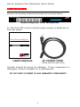
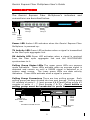
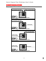
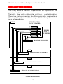
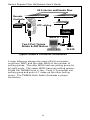
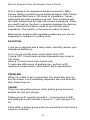
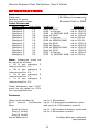
Gemini Express Fiber Multiplexer
User’s Guide
Document # 62-400260101
Rev. D
February, 2007
Gemini Express Fiber Multiplexer User’s Guide
TABLE OF CONTENTS
TABLE OF CONTENTS ................................................... 2
SAFETY ......................................................................3
INTRODUCTION ..........................................................5
UNPACKING................................................................6
ACTIVE PAIR SETUP.....................................................7
DESCRIPTION .............................................................9
CONFIGURATION....................................................... 11
MODE DESCRIPTION.................................................. 11
MODE DESCRIPTION.................................................. 12
COLLAPSED RINGS .................................................... 13
CONNECTIONS.......................................................... 14
INSTALLATION.......................................................... 18
GLOSSARY ............................................................... 21
PROBLEM SOLVING ................................................... 22
SPECIFICATIONS....................................................... 28
WARRANTY STATEMENT ............................................. 30
Document # 62-400260101
Gemini Express Fiber Multiplexer User’s Guide
SAFETY
NOTE: READ THIS FIRST
1) Do not look into any fiber optic connection or fiber optic
cable.
2) Do not connect Gemini Express Fiber Multiplexer to any
type of public network.
3) Do not connect any outdoor cabling to the Gemini
Express Fiber Multiplexer without proper lightning
protection.
4) Do not use unauthorized power supplies or cables.
5) Do not connect to non-5250 protocol devices.
6) Do not disassemble or modify the power supply and its
cables.
7) Disconnect all cables prior to configuration.
8) Devices attached to the UTP network must comply with
the voltage and current limits for Class 2 Power-Limited
Signal Circuits as defined by article 725 of the National
Electrical Code and Section 16 of the Canadian Electrical
Code.
9) For your safety, receptacles must be properly wired and
grounded.
10) Never attempt to service equipment connected to the
data cable network or the grounded receptacle during an
electrical storm. Exposure to lethal voltages may occur
when lightning is present.
3
Gemini Express Fiber Multiplexer User’s Guide
The following FCC statement applies to the NLynx Gemini
Express Fiber Multiplexer.
Federal Communications Commission (FCC) Statement
This equipment has been tested and found to comply with
the limits for a Class A digital device, pursuant to Part 15 of
the FCC Rules.
These limits are designed to provide
reasonable protection against harmful interference when the
equipment is operated in a commercial environment. This
equipment generates, uses, and can radiate radio frequency
energy and, if not installed and used in accordance with the
instruction manual, may cause harmful interference to radio
communications.
Operation of this equipment in a
residential area is likely to cause harmful interference, in
which the user will be required to correct the interference at
your own expense. Unauthorized changes or modifications
could void the user’s authority to operate the equipment.
This device complies with Part 15 of the FCC Rules.
Operation is subject to the following two conditions: (1)
this device may not cause harmful interference, and (2) this
device must accept any interference received, including
interference that may cause undesired operation.
Classification of LED Transmitter Device Important:
The optical transmitter contains an LED system and is
classified “CLASS 1 LED PRODUCT” per EN60825-1 (+A11),
Safety of Laser Products. Contact Ringdale for repair if your
Gemini
Express
Fiber
Multiplexer
ever
requires
maintenance.
Document # 62-400260101
Gemini Express Fiber Multiplexer User’s Guide
INTRODUCTION
This user's manual is for the Gemini Express Fiber
Multiplexer for use with the IBM 5250 protocol. The 5250
family of products consists of the IBM's System 34, 36, 38,
and the AS/400 along with many supporting devices
manufactured by IBM and other companies. The Gemini
Express Fiber Multiplexer works with all devices that are
designed within the 5250 specifications.
Gemini Express Fiber Multiplexer
Ringdale’s
Gemini
Eight-Port
Express
Fiber
Optic
Multiplexer, part number 00-31-2313-0001, offers the
unique ability to allow multiple AS/400 controller polling
groups to be transmitted over a single fiber optic pair. This
feature allows all new AS/400e controllers to provide their
maximum throughput potential, in either 1Mbps Optimized
or 2Mbps Express mode, by transparently multiplexing the
"split-polling" feature without requiring performance robbing
PTF's.
All new IBM controllers support the "split-polling"
feature as a means of achieving higher throughput rates,
even when connected to standard legacy devices. The
Gemini Express Multiplexer allows the "split-polling" feature
to remain "enabled" with performance of up to 4 times
greater than standard legacy 1Mbps 5250 protocols.
The Gemini Express Multiplexer has 8 Shielded RJ45 port
connections as well as a DB25 "direct-connection"
eliminating the need for the twinax "brick" and associated
twinaxial cabling. Link connectivity is via ST fiber optic
multi-mode connection with ability to operate in both pointto-point and multi-point "ring" topologies, reducing
hardware requirements by up to 50%.
Other features include Advanced Noise Filtering, LED Port
Diagnostics, Configurable UTP Pin Assignments, and a Field
Replaceable wide-ranging Power Supply.
5
Gemini Express Fiber Multiplexer User’s Guide
UNPACKING
Remove the packing material and check for the items below:
Gemini Express Fiber Multiplexer
A (100-240 VAC) input external power supply is attached on
the rear panel.
Gemini Express Multiplexer
User’s Guide
USER'S MANUAL
AC POWER CORD
(North American units only)
Visually inspect all items for damage. If any component is
damaged, contact Ringdale for a replacement.
DO NOT APPLY POWER TO ANY DAMAGED COMPONENT!
6
Gemini Express Fiber Multiplexer User’s Guide
ACTIVE PAIR SETUP
All Gemini Express Fiber Multiplexers can be factory
configured per customer request.
The factory default
MODEL GXM8-45
PINS
4/5 3/6 1/2
S/N
xxxxxxxxxx
setting is Pins 4 & 5.
Different configurations will be
indicated on the label on the bottom of the unit.
IDENTIFICATION LABEL
The active pair may be re-configured by performing the
following procedure:
•
•
•
•
Disconnect all power to the unit.
Remove the two top cover screws located on the rear
panel.
Gently slide the top cover back one inch.
Hold the top cover and tilt it up.
Reconfigure the jumpers located behind the RJ45 connectors
as required.
Settings for polarity and active pair
assignment are shown below:
ACTIVE PAIR JUMPER SETTINGS
It should be noted that connections to the DB25 and the
RJ45s are mutually exclusive. If any of the three pairs of
the RJ45 are selected, the DB25 is disconnected. If the
DB25 is selected, the RJ45s are disconnected. All jumper
settings must be identical. To reinstall the top cover, tilt
the top cover down, and slide the top cover forward until it
mates completely with the bottom cover. Install the 2 top
cover screws.
7
Gemini Express Fiber Multiplexer User’s Guide
RJ45
RJ45 (4/5)
RJ45
RJ45
RJ45 (3/6)
8
RJ45 (1/2)
RJ45
DB25
Gemini Express Fiber Multiplexer User’s Guide
DESCRIPTION
The Gemini Express Fiber Multiplexer’s indicators and
connections are described below.
Power
LED
Polling
Group 1
Polling
Group 2
Fiber
Status
LEDs
Power LED Amber LED activates when the Gemini Express Fiber
Multiplexer is powered up.
TX Activity LED Green LED activates when a signal is transmitted
to the fiber optic aggregate link.
RX Activity LED Green LED activates when a signal is received
from the fiber optic aggregate link and the MULTIPLEXER
synchronizes to it.
Polling Group Status LEDs The upper green LEDs are express
mode indicators. These LEDs activate when an express signal is
detected and remain on until a 1MBPS signal is detected or a
system reset occurs. The lower green LEDs are data activity
indicators. These LEDs activate when a signal is present.
Polling Group Connectors There are two polling groups. Each
polling group has been divided into two port groups. Polling group
#1 consists of ports 0 - 3 (port groups A & B) and Polling group #2
consists of ports 4 - 7 (port groups C & D). Ports within a
polling group must be connected to ports from a common
PRODUCT
IDENTIFICATION
LABEL
DB25
FCC LABEL
FIBER
OPTIC
LINK
EXTERNAL POWER SUPPLY
DC POWER
CONNECTION
REAR VIEW
9
CONFIGURATION
SWITCHES
Gemini Express Fiber Multiplexer User’s Guide
controller.
10
Gemini Express Fiber Multiplexer User’s Guide
CONFIGURATION
The configuration switch settings are shown below.
POINT TO POINT MODE
HOST SIDE MULTIPLEXER
ON
LEGEND
SWITCH 1: ON
SWITCH 2: ON
1
2
CONFIGURATION SWITCHES
HOST SIDE MULTIPLEXER
ON
RING MODE
LEGEND
SWITCH 1: ON
SWITCH 2: OFF
1
2
CONFIGURATION SWITCHES
POINT TO POINT MODE
ON
DEVICE SIDE
MULTIPLEXER
LEGEND
SWITCH 1: OFF
SWITCH 2: ON
1
2
CONFIGURATION SWITCHES
ON
DEVICE SIDE
MULTIPLEXER
LEGEND
SWITCH 1: OFF
SWITCH 2: OFF
RING MODE
1
2
CONFIGURATION SWITCHES
11
Gemini Express Fiber Multiplexer User’s Guide
MODE DESCRIPTION
A “POINT TO POINT” link is comprised of two Multiplexers
connected by a single backbone. A diagram of a “POINT TO
POINT” link is provided below.
TX
RX
HOST PORT
CONNECTIONS
DEVICE
CONNECTIONS
FIBER OPTIC BACKBONE
RX
TX
MULTIPLEXER
MULTIPLEXER
Multiple Multiplexers which are connected in series with
fiber optic transmit to fiber optic receive constitute a “RING”
topology. A diagram of a “RING” application is provided
below.
DEVICE
CONNECTIONS
RX
TX
TX
HOST PORT
CONNECTIONS
RX
FIBER OPTIC BACKBONE
TX
RX
TX
RX
MULTIPLEXER
MULTIPLEXER
DEVICE
CONNECTIONS
12
DEVICE
CONNECTIONS
Gemini Express Fiber Multiplexer User’s Guide
COLLAPSED RINGS
The Ring mode is seldom implemented as depicted in the
previous section.
Typically, fiber optic cables star out from a central location.
Therefore, interconnecting the fiber optic star segments at
the central location creates a ring. This technique is known
as a collapsed ring.
MDF
FIBER OPTIC
PATCH PANEL
FIBER
OPTIC
JUMPERS
HOST MULTIPLEXER
TX RX
IDF
TX RX
REMOTE MULTIPLEXER # 1
IDF
TX RX
REMOTE MULTIPLEXER # 2
IDF
TX RX
REMOTE MULTIPLEXER # 3
COLLAPSED RING
13
Gemini Express Fiber Multiplexer User’s Guide
CONNECTIONS
62.5 micron multimode
GXM
GXM
STARS
UTP cabling
PATCH
PANEL
Balun & T cable
AS/400
8 Port Twinax Brick
ASF Baluns. See
below for
WALL
PLATE
Typical AS/400 Installation
14
Gemini Express Fiber Multiplexer User’s Guide
62.5 micron multimode
GXM
GXM
UTP cabling
STAR
PATCH
PANEL
AS/400
Balun & T cable
DB25 to DB25
STP CABLE
WALL
PLATE
AS/400 TWINAX Brick Detail
TO AS/400 WSC
TO GXM
POLLING GROUP# 1
POLLING GROUP# 2
PORT# 0
ASF BALUN
0
PORT# 1
ASF BALUN
1
PORT# 2
ASF BALUN
2
PORT# 3
ASF BALUN
3
TO GXM
4
ASF BALUN
PORT# 4
5
ASF BALUN
PORT# 5
6
ASF BALUN
PORT# 6
7
ASF BALUN
PORT# 7
PORT & POLLING GROUP ASSIGNMENTS
ON THE TWINAX BRICK FOR THE NEW AS/400 WSC
WITH SPLIT POLLING FEATURE
FRONT VIEW
Typical AS/400 Direct Connect Installation
15
Gemini Express Fiber Multiplexer User’s Guide
62.5 micron multimode fiber
Remote
Controller
GXM8
GXM8
GXM8
UTP cabling
STARS
PATCH
PANEL
Balun & T cable
Two 4 Port Twinax
Bricks & ASF Baluns
WALL
PLATE
Typical Remote Controller Installation
A major difference between the newer AS/400 workstation
controllers (WSC) and the older WSCs is the number of
polling groups. The older WSCs had one polling group for
all eight ports. The newer WSCs have two polling groups.
Divide the TWINAX brick in two. Ports 0-3 comprise one
polling group and ports 4-7 make up the other polling
group. The TWINAX Brick Detail illustrates a proper
connection.
16
Gemini Express Fiber Multiplexer User’s Guide
62.5 micron multimode fiber
SYSTEM 3X
GXM8
GXM8
UTP cabling
STAR
PATCH
PANEL
Balun & T cable
Up to 8 Twinax Ports
& ASF Baluns
Typical System 3X Installation
17
WALL
PLATE
Gemini Express Fiber Multiplexer User’s Guide
INSTALLATION
INSTALLATION
Host side multiplexer installation
1. Set the configuration switches on the rear panel of the
host side Gemini Express Fiber Multiplexer as
follows:
SWITCH 1 ON SWITCH 2 ON for point-to-point.
or
SWITCH 1 ON SWITCH 2 OFF for a ring application.
2. The Gemini Express Fiber Multiplexer is designed for a
19” rack. The unit should be properly installed using all
four mounting holes. Rack hardware is not provided. It
is recommended that plastic or nylon washers be used
under mounting screws to protect the chassis’s finish.
3. A polling group is a group of ports that have one port
active at a time.
The new AS/400 workstation
controllers (WSC) have two polling groups. Ports 0-3
and ports 4-7 constitute the two groups. The Gemini
Express Fiber Multiplexer can accommodate two polling
in the same fashion.
The Gemini Express Fiber
Multiplexer polling group #1 consists of ports 0-3 and
Gemini Express Fiber Multiplexer polling group #2
consists of ports 4-7. Do not connect more than one
host-polling group to a Gemini Express Fiber
Multiplexer polling group. Connect the host ports to
the Gemini Express Fiber Multiplexer ports.
WARNING
DO NOT LOOK INTO ANY FIBER OPTIC
CONNECTOR OR FIBER OPTIC CABLE!
4. The Gemini Express Fiber Multiplexer has ST style fiber
optic connectors. Connect the multimode fiber optic
cables to the optical link connectors located on the rear
panel of the MULTIPLEXER. Note the fiber color or
number on the “TX’ & “RX” to ensure proper connection
at the remote multiplexer location. Strain relieve and
label all cables.
18
Gemini Express Fiber Multiplexer User’s Guide
5. The external power supply is mounted on the rear panel of
the Gemini Express Fiber Multiplexer. The AC power cord
must be firmly inserted into the external power supply and
strained relieved.
6. Insert the male end of the AC power cord into a properly
wired receptacle. All data & mode LED’s on the Gemini
Express Fiber Multiplexer will activate for two seconds and
fade off. The amber power LED on the front panel, the
green power led on the top of the external power supply,
and the TX LED will activate and remain on. At this time
the data activity LEDs will flash at the host’s polling rate.
The RX LED will be off until the remote Multiplexer is
installed.
Device side Multiplexer installation.
1. Set the configuration switches on the rear panel of the
device side Gemini Express Fiber Multiplexer as follows:
SWITCH 1 OFF
SWITCH 2 ON
for a point-to-point application
or
SWITCH 1 OFF
SWITCH 2 OFF
for a ring application
2. The Gemini Express Fiber Multiplexer is designed for a 19”
rack. The unit should be properly installed using all four
mounting holes. Rack hardware is not provided. It is
recommended that plastic or nylon washers be used under
mounting screws to protect the star’s finish.
WARNING:
DO NOT LOOK INTO ANY FIBER OPTIC
CONNECTOR OR FIBER OPTIC CABLE!
19
Gemini Express Fiber Multiplexer User’s Guide
3. The Gemini Express Fiber Multiplexer has ST style fiber
optic connectors.
For point to point applications,
connect the multimode fiber optic cable attached to the
host side Multiplexer ’s ”TX” to the device side
multiplexer ’s ”RX” optical link connector located on the
rear panel of the Gemini Express Fiber Multiplexer, and
connect the multimode fiber optic cable attached to the
host side Multiplexer ’s ”RX” to the device side
Multiplexer ’s ”TX” optical link connector located on the
rear panel of the Gemini Express Fiber Multiplexer. For
ring applications, connect the fiber optic TX of a
Multiplexer to the fiber optic RX of the next multiplexer
down stream in the ring until the ring is complete.
Ensure that the cables are properly strained relieved and
labeled.
4. Connect the Gemini Express Fiber Multiplexer ports to
the host ports of the GEMINI active or passive star and
follow the installation procedure for the star.
5. The external power supply is mounted on the rear panel
of the Gemini Express Fiber Multiplexer. The AC power
cord must be firmly inserted into the external power
supply and strained relieved.
6. Insert the male end of the AC power cord into a properly
wired receptacle. All data & mode LED’s on the Gemini
Express Fiber Multiplexer will activate for two seconds
and fade off. The amber power LED on the front panel,
the green power LED on the top of the external power
supply, and the “TX & RX” LEDs will activate and remain
on. If any terminals are on, the data activity LEDs will
activate. If express devices and an express host, are
attached, the port status LEDs (upper green LEDs) will
activate. Devices in a ring application will not show a
sign on screen until the ring is complete.
20
Gemini Express Fiber Multiplexer User’s Guide
GLOSSARY
ASF – Advanced System Filtered Terminated.
Balun – A balun converts from a balanced to an un-balanced
cable. Twinaxial wiring is balanced. UTP is not.
Twinaxial – Cabling used by IBM. It has two wires and a
shield. It provides known impedance.
UTP – Unshielded Twisted Pair cabling is the most common
cable used in computer networking. It is a variant of twisted
pair cabling. UTP cables are often called Ethernet cables
after Ethernet, the most common data-networking standard
that utilizes UTP cables, however in this use it is not
Ethernet. In contrast to STP cabling, UTP cable is not
surrounded by any shielding. It is the primary wire type for
telephone usage and is very common for computer
networking, especially in patch cables or temporary network
connections due to the high flexibility of the cables.
21
Gemini Express Fiber Multiplexer User’s Guide
PROBLEM SOLVING
If problems are encountered with the Gemini Express Fiber
Multiplexer, the following guideline is intended to provide a
quick resolution.
1. Collect all information relevant to this application.
•
Gemini Express Fiber Multiplexer serial numbers
•
Host type and operating system software level.
•
Quantity, and type of peripheral devices.
•
Interconnecting cable types and distances.
•
Equipment environment.
•
Interconnection diagrams.
2. Setup the application with all Multiplexers in one room
interconnected with fiber optic jumpers. Verify the
application with a host port and a terminal.
3. Search through the common problems and possible
causes provided below.
The Gemini Express Fiber Multiplexer front panel power
LED is off!
•
•
Verify that the AC & DC connections are proper.
Verify that the AC outlet is functioning correctly.
If the problem persists, observe the status of the external
power supply’s LED and contact Ringdale’s technical
support.
The Gemini Express Fiber Multiplexer RX LED is off or
flashing!
•
•
Verify that the fiber optic connectors are properly
connected.
Verify that the fiber optic budget and distance has
not been exceeded.
The Gemini Express Fiber Multiplexer TX LED is off!
•
Contact Ringdale technical support.
22
Gemini Express Fiber Multiplexer User’s Guide
A device is down or unstable!
•
•
•
•
•
•
•
•
•
•
•
Verify that there is one host-polling group per Gemini
Express Fiber Multiplexer polling group.
Verify that the host’s device type matches the device.
Verify that the host workstation controller’s (WSC)
capacity has not been exceeded.
Verify that the device is properly terminated. A
peripheral is terminated when its twinaxial port has two
54.9-ohm resistors located between the “A” phase pin &
earth ground and the “B” phase pin & earth ground.
Termination is provided by a “Y” or “T” cable assembly
or by a terminating balun (i.e. ASFT series).
Verify that there are no polarity reversals in the cable.
Verify that the cable distance does not exceed the
Gemini Express Fiber Multiplexer specification.
Verify that the cable is data grade.
Verify that the wiring uses natural pairs.
Verify that the wiring avoids sources of environmental
noise.
Verify that the balun’s pinout matches the Gemini
Express Fiber Multiplexer ’s pinout.
Verify that the host side balun’s pinout/polarity match
the device side balun’s pinout/polarity.
Devices interfere with each other!
•
•
•
Verify that there is one host-polling group per Gemini
Express Fiber Multiplexer polling group.
Verify that devices on star segments have unique
addresses.
Verify that all devices are properly terminated.
Devices cannot operate in Express mode!
•
•
•
•
Verify that the host and the device are capable of
Express mode.
Verify that all interconnecting components support the
Express mode.
Verify that all devices on the port are Express ready.
Verify that all cable distances are within the Express
specification.
23
Gemini Express Fiber Multiplexer User’s Guide
•
The controller may have down shifted to 1MBPS due to
errors during installation. The controller will retry the
Express mode in approximately one hour.
Flashing Express LEDs!
•
Determine the number of Express devices on the port. If
there are less than seven devices, the flashing Express
LED is normal.
Express LED on without data activity!
•
If the host is disconnected during an express connection,
the express LED remains on.
PROBLEM:
Some terminals come up, and then go back down. The cursor
jumps from the upper left, to the upper right.
CAUSE:
This is typical of a station address conflict. A common
misunderstanding with hubs is that you do not have to observe
station address conflicts.
SOLUTION:
You cannot duplicate station addresses on the same hub.
PROBLEM:
The first terminal comes up, but then drops.
CAUSE:
If you move off of a balanced network (twinax) to an
UNbalanced network (balUN) what you are UNbalancing is the
impedance.
24
Gemini Express Fiber Multiplexer User’s Guide
SOLUTION:
You can make it up on one of RJ45 ends at the cost of
decreasing the maximum cable distance, or you can add a bit
of cable, OR you can use baluns that have a short piece of
twinax tail. Some balun manufacturers recommend a minimum
cable length of 15 feet.
PROBLEM:
It does not work at all.
CAUSE:
You could have a polarity mismatch. Twinax has two
conductors, (so that means 2 Tips, and Zero rings), so you
cannot truly say that any balun is Tip or Ring. The two
conductors on Twinax cable are called Phase A and Phase B.
All that you can say is which pins are active, and which pins of
the RJ connector connects to A or B of the Twinax connector.
SOLUTION:
Our Gemini hubs use auto-sensing and don't care what baluns
are on the hinter ends, but you must match the polarity of the
host connection to the ports. If you use passive hubs, or
connect the baluns back to back, the baluns must be in pairs.
Flip the connector by snipping the cable, flipping and putting a
new connector on. If most devices are working you will change
the devices that do not work. If none work, then you should
change the host end.
PROBLEM:
The first terminal works, the last terminal works, but the ones
in between, do not.
CAUSE:
25
Gemini Express Fiber Multiplexer User’s Guide
This is typical of an impedance balance mismatch. IBM's
Twinax cabling connections use balanced signal. With Twinax
it is required that there is 100 ohms of impedance. Twinax
cable itself provides impedance as well. This combined with
the other components provides the correct impedance. When
you use RJ wiring, the direct connection between the devices
is lost. Therefore the balun needs to provide that same
impedance. The resistor in the balun provides 45 ohms.
Because the problem with impedance balancing you are not
supposed to configure in a daisy chain.
SOLUTION:
If you are configured with a daisy chain, carefully resolve your
impedance balancing.
If not, do not use flat (silver satin) cable. Only UTP.
If using STP, it must have nominal impedance very close to
100 ohms.
Allow a 10-foot service loop at each end.
To estimate differences of existing wire, perform a DC
resistance measurement. Must match balun specification.
PROBLEM:
When he is able to get a connection, the terminals come up,
but the screen is not completely displayed, they are slow and
then finally drop out.
CAUSE:
There are two polling groups. Each polling group has been
divided into two port groups.
Polling group #1 consists of ports 0 - 3 (port groups A & B)
and polling group #2 consists of ports 4 - 7 (port groups C &
D).
Ports within a polling group must be connected to ports from a
common controller.
26
Gemini Express Fiber Multiplexer User’s Guide
The reason for this is to support the new AS/400 Split
Controller function used in the 5250 Express Data Stream.
It splits the addresses 0-3 and 4-7 logically
SOLUTION:
When plugging the CAT5 connections in, make certain that
the workstation addresses are grouped such that the devices
in addresses 0-3 are in the same group and 4-7 are in a
different group from the 0-3 group.
27
Gemini Express Fiber Multiplexer User’s Guide
SPECIFICATIONS
Protocol
Data rate
Number of ports
Port connector types
Cable Distances
Cable Type
Data Rate
Category 3
1X
Category 3
1X
Category 3
1X
Category 3
2X
Category 3
2X
Category 3
2X
Category 5
1X
Category 5
1X
Category 5
1X
Category 5
2X
Category 5
2X
Category 5
2X
5250
1 & 2Mbps (transparent)
8
Shielded RJ45 or DB25
Location
Host to GXM
GXM to Device
GXM to GEMINI HUB
Host to GXM
GXM to Device
GXM to GEMINI HUB
Host to GXM
GXM to Device
GXM to GEMINI HUB
Host to GXM
GXM to Device
GXM to GEMINI HUB
Distance
up to 2000 ft
up to 1800 ft
up to 1000 ft
up to 1000 ft
up to 900 ft
up to 500 ft
up to 2000 ft
up to 2200 ft
up to 1200 ft
up to 1500 ft
up to 1650 ft
up to 900 ft
Note: Distances must be
de-rated as follows:
• 62 ft per category 3
interconnect for 1X.
• 38 ft per category 3
interconnect for 2X.
• 16 ft per category 5
interconnect for 1X.
• 11 ft per category 5
interconnect for 2X.
Cable distances over 1000’
must be de-rated by 25%
for ring applications.
Distance
(fiber optic backbone)
62.5
micron
multimode
fiber
up to 2 Kilometers
up to 1.5 Kilometers between units
and up to 4.5 Kilometers overall.
Point to Point
Ring (3 Units)
Ring (4 Units)
Active data pins
up to 1 Kilometers between units and
up to 4 Kilometers overall.
Configurable per customer
requirement
28
Gemini Express Fiber Multiplexer User’s Guide
Optical Specifications
Fiber-optic budget
(point-to-point)
12 dB (typical)
10 dB (typical)
8 dB (typical)
820 nanometers
two ST style
Fiber optic budget (ring)
3 unit ring
4 unit ring
Peak power wavelength
Fiber optic connectors
Power requirements
Power supply type
Dimensions
Warranty
90 to 250 VAC at 50 to 60 Hz
External
1.75" x 19" (1U)
Three years
29
Gemini Express Fiber Multiplexer User’s Guide
WARRANTY STATEMENT
This Ringdale product is warranted to be free from defects in
material and workmanship for a period of three years from
the date of purchase.
Ringdale’s liability under this
warranty is limited to cure, repair, or replacement of the
product. Ringdale shall not be liable for injury, property
damage or other direct, or direct consequential damage,
including but not limited to loss of profits or other damage
or expenses arising directly or indirectly from the
installation, removal, maintenance, use or non-use of the
product used separately or in combination with other
equipment.
These warranties shall become void where it is determined,
at the sole discretion of Ringdale, that the product has been
exposed to excessive physical or operational abuse, acts of
God, or theft. Repairs performed by someone other than by
Ringdale will void this warranty. This warranty is in lieu of
any and all other warranties, expressed or implied, by
Ringdale representatives or distribution, including fitness for
particular purpose and merchantability.
The customer may, at their option, purchase an Assist
Service Agreement that would provide same day overnight
shipping response for field replacement of faulty equipment
to maintain your data communication system while
equipment repairs are completed.
Contact our Sales
department for further details.
30
Gemini Express Fiber Multiplexer User’s Guide
RETURN MERCHANDISE PROCEDURE
In the event that the product is not as warranted, the
customer must contact Ringdale for a return merchandise
authorization number (RMA#) before returning the product
to the Ringdale facility in Georgetown, Texas, USA. Out of
warranty repairs are available on a time and materials
basis. The customer must contact Ringdale for a return
merchant number (RMA#) prior to shipping the
malfunctioning unit to Ringdale. The customer is
responsible for all shipping and insurance charges to and
from Ringdale facility in Georgetown, Texas, USA.
Ringdale, Inc.
101 Halmar Cove
Georgetown, Texas USA 78628
Toll-free: (888)-288-9080
Tel.: (512) 288-9080
Fax: (512) 869-2621
www.nlynx.com
www.ringdale.com
31