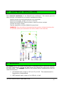
1
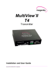
STA-RITE
®
SR6000S
POOL / SPA
CONTROLLER
Software Version
SR6000S Release A1
Feb. 28, 2003
INSTALLATION &
OPERATION GUIDE
STA-RITE INDUSTRIES
293 Wright Street
Delavan, WI 53115
Ph (800) 752-0183
STA-RITE INSTALLATION & OPERATION GUIDE
1
Table of Contents:
SAFETY PRECAUTIONSa .................................................................................................. 3
WARRANTY .......................................................................................................................... 4
1.0 SR6000S OVERVIEW...................................................................................................... 4
1.1 MODEL SR6000S ............................................................................................................ 6
1.2 INTRODUCTION ............................................................................................................. 6
1.3 IMPORTANCE OF WATER MAINTENANCE............................................................... 6
2.0 INSTALLATION PROCEDURES ....................................................................................... 7
2.1 INSTALLATION PREPARATION ................................................................................. 7
2.2 MOUNTING THE SR6000S ........................................................................................... 7
2.3 PLUMBING INSTALLATION ....................................................................................... 8
2.4 FLOW OR PRESSURE SWITCH ..................................................................................... 9
2.5 ELECTRICAL SPECIFICATIONS................................................................................... 9
2.6 ELECTRICAL INSTALLATION.................................................................................. 10
2.7 SENSORS ........................................................................................................................ 10
2.8 PH AND ORP ELECTRODES ......................................................................................... 11
2.9 ELECTRODE CARE ..................................................................................................... 11
2.10 FINISHING AND TESTING ....................................................................................... 12
3.0 OPERATION OF SR6000S ........................................................................................... 13
3.1 INTRODUCTION ................................................................................................................ 13
3.2 LED SUMMARY TABLE ............................................................................................. 13
3.3 INITIALIZING THE SR6000S ............................................................................................. 14
3.4 READING DISPLAY........................................................................................................... 14
3.5 MANUAL FEED ................................................................................................................. 15
3.6 PH AND ORP MENU ITEMS ............................................................................................... 15
3.7 PH / ORP SET POINTS ...................................................................................................... 16
3.8 CYCLE TIME ..................................................................................................................... 16
3.9 ON TIME LIMIT................................................................................................................. 17
3.10 CALIBRATION ................................................................................................................. 18
3.11 CALIBRATING PH........................................................................................................... 18
3.12 CALIBRATING ORP .......................................................................................................... 18
3.13 OVERFEED TIME LIMIT ................................................................................................. 19
4.0 ADVANCED MENU ............................................................................................................ 19
4.1 CLEAR PH......................................................................................................................... 20
4.2 CLEAR ORP..................................................................................................................... 20
4.3 ACID OR BASE SELECT .................................................................................................... 21
4.4 SET PASSWORD ................................................................................................................. 21
4.5 RESET ALL ..................................................................................................................... 22
5.0 TROUBLESHOOTING ......................................................................................................... 22
5.1 PUMP MAINTENANCE ............................................................................................... 24
5.2 PUMP TUBE REPLACEMENT .................................................................................... 24
5.3 MAXIUM CHEMICAL CONCENTRATIONS ............................................................ 25
6.0 APPENDIX B: CHEMICAL STANDARDS ............................................................................... 25
STA-RITE INSTALLATION & OPERATION GUIDE
2
SAFETY PRECAUTIONSa
PLEASE READ THIS USER MANUAL completely before installing or operating the
equipment. The SR6000S is a Class 1 product for protection against electric shock and a
Type 1 product with regards to disconnection of the control circuits.
Be sure to observe the following safety precautions:
a– Do not permit anyone untrained or under the age of 18 to use this product.
a– Unit must be properly connected to earth ground.
a– Never apply power when front panel is not secured in the closed position.
a– Never service unit with power applied, always turn OFF main circuit breaker to unit and
all equipment when servicing.
a– Do not disassemble. Touching the controller’s internal parts could result in injury. In
case of a malfunction, only a qualified technician should repair the controller.
a– Risk of Electric Shock. Connect only to a grounding type receptacle protected by a
ground-fault circuit interrupter (GFCI). Contact a qualified electrician if verification on the
receptacle is not protected by GFCI.
a – Do not bury cord. Route cord to eliminate abuse from heater exhaust, lawn mowers,
hedge trimmers, and other equipment.
a– Be careful not to damage any of the cord insulation. Should the cord be damaged,
return it to your dealer for a replacement. Continued use could result in fire or electric
shock.
a– To reduce the risk of electric shock, do not use an extension cord to connect unit to
electric supply; provide a properly located GFCI.
a– Never remove or install any cables between the circuit cards when power is applied,
damage to the components may occur.
WARNING: DANGER - CHEMICAL BURN HAZARD - If possible, make sure
pumps are OFF before drilling into pipes. Securely fasten all electrical, water and
chemical lines. Locate chemical feed pumps and chemical storage tanks in a safe
and secure area. Never turn chemical feed pumps ON when both flow cell valves
are closed. The feed lines will blow off and spray full strength chemicals on you or
anyone near the equipment
SAVE THIS INSTRUCTION GUIDE!
STA-RITE INSTALLATION & OPERATION GUIDE
3
WARRANTY
STA-RITE INC. warrants the SR6000S to be free from defects in
manufacturing and workmanship for a period of Three (3) YEARS from the
date of manufacture for the electronic module. All sensors and flow cells
have a warranty of one (1) year. Other equipment is covered by
manufacturer's own warranty. During the warranty period, any defective
parts will be repaired or replaced when necessary by Sta-Rite.
This warranty does not cover: (a) the buyers' labor or any servicing fees
related to replacement of the Product; (b) damage resulting from the use
of this Product in other than its normal manner; (c) damage from misuse,
accident or neglect; (d) damage from improper testing, operation, or
installation; (e) not operating the Product on a dedicated (separate) circuit
or under conditions other than those recommended or at voltages or
amperages other than the voltage or amperage indicated on the Product;
and (f) acts of Mother Nature (i.e. lightning, electrical storms, floods, etc.).
In addition, attempting to service or modify the Product will render this
Warranty Void. Defective parts should be returned immediately to the
local Sta-Rite dealer, any parts returned to the factory require a return of
material authorization code.
WARRANTY CARD MUST BE COMPLETED AND RETURNED AT ONCE.
1.0 SR6000S OVERVIEW
Sta-Rite, the technological leader in swimming pool automation, congratulates you on
your selection of the SR6000S swimming pool controller. The SR6000S is specifically
designed to be easy to use and install while meeting the needs of the most demanding
applications.
Some of the more outstanding features include:
SUMMARY: The SR6000S is an automation system capable of continuous monitoring
and control of water chemistry.
PROGRAMMABLE FEATURES: Programmable chemical feed cycle on and off times, set
points that specify the pH and ORP set points, selection of pH acid or base feed, off at set
point, off if no flow, overfeed and password protection.
DISPLAY: The SR6000S includes two (2) digital displays with three (3) decimal points
each. These displays are visible from distance of over twenty (20) feet and are visible at
night.
STA-RITE INSTALLATION & OPERATION GUIDE
4
LED: The SR6000S uses five (5) indicator LED’s including Flow, ORP Alarm, ORP Feed,
pH Alarm and pH Feed.
BUTTONS: The SR6000S includes five (5) buttons for accessing and changing all
parameters.
MEMORY: In case of power loss the SR6000S shall retain all programmed values. The
values are protected for at least five (5) years without having power applied.
SECURITY: The SR6000S has a password feature to disable the buttons remotely and on
sight.
ALARMS: If the pH or ORP is more than 5% away from set point for 10 minutes or more
the SR6000S will light the LED alarm LEDS.
BUILT IN CHEMICAL FEEDERS: Two 24 volt chemical feed pumps are built onto the
sides of the SR6000S for ease of use and installation.
SENSORS: The SR6000S directly measures pH and ORP. Each sensor has its own
isolated circuitry for direct measurement, without the need for addition hardware of
electronics.
VOLTAGE: The SR6000S includes a selector switch to select the input voltage of 110 or
220 VAC (single or two phase). Both the line and neutral voltages are fused at 5A; the
relay power is routed through a 1A fuse.
STA-RITE INSTALLATION & OPERATION GUIDE
5
1.1 MODEL SR6000S
The SR6000S is a chemical controller capable of maintaining water quality, by
monitoring the ph and ORP of a water source and by automatically feeding chemicals with
two built-in feed pumps. The chemical levels are tightly controlled with timed feed cycles.
To prevent overshoot the feed time has a 5% proportional adjustment. At 5% away form
set point the feed pump will be a maximum feed time. Within 5% of set point the feed
time will decrease linearly as set point is approached.
1.2 INTRODUCTION
The SR6000S INSTALLATION AND OPERATION MANUAL explains the procedures for proper
installation and operation of the SR6000S series controller.
Chapter two (2) the
Installation section, introduces the parts of the controller and the process to follow when
installing the electrical and plumbing portions. Chapter three (3) the Programming and
Operation, describes all the available functions of the controller, from navigating to
initializing the SR6000S.
If there are any questions after reading this manual, please contact your local Sta-Rite
dealer or Sta-Rite directly.
1.3 IMPORTANCE OF WATER MAINTENANCE
The SR6000S will effectively maintain the bacteriological and physiological requirements
of state and local Health Departments. In addition, the SR6000S helps to protect the
equipment from the effects of improper water balance.
The National Swimming Pool Foundation recommends the following guidelines for
chemical automation, (local health codes may differ):
Filtration – Minimum turnover rate of six (6) hours for a pool and thirty (30) minutes for
a spa.
Water Balance – pH 7.2 – 7.6, alkalinity 80-120 PPM.
Oxidation Reduction Potential (ORP) – A minimum 650 mV to maximum 750 mV the
preferred.
Total Dissolved Solids – Should not exceed 2000 PPM.
STA-RITE INSTALLATION & OPERATION GUIDE
6
2.0 INSTALLATION PROCEDURES
Listed below are the instructions and information necessary to install your SR6000S
chemical controller system.
2.1 INSTALLATION PREPARATION
As soon as the controller is received, check the shipping carton carefully for damage and
report any directly to the shipping company. Use care when unpacking equipment to avoid
damage or loss of small parts. Go through the shipping list and if anything is missing,
please contact your local Sta-Rite dealer.
•
The SR6000S is a simple product to install and begin using. Mapping out
connections prior to installation is recommended.
The location of the SR6000S
must be optimized for both electrical and plumbing connections.
•
Sta-Rite sends the SR6000S from the factory set to the 110 VAC supply power, in
order to simplify installation.
2.2
MOUNTING THE SR6000S
Select a location for mounting the SR6000S, meeting the following recommendations:
At least ten (10) feet from open water.
Close enough for the supplied power cord to reach the supply voltage. The controller will
not operate properly without a solid earth ground connection. WARNING: Proper and safe
operation requires an earth ground connection.
Supply power must be routed to the SR6000S in accordance with the applicable codes in
the area; the supplied cord is not code in some areas.
WARNING: Keep the SR6000S out of direct sunlight and if possible inside a room, a
shade screen must be used for outdoor installations.
The installation surface must be solid and vertical. Do not mount the controller in a
horizontal position.
Maintain adequate clearance for opening the enclosure.
The environment should be free of chemical fumes and excessive heat. The maximum
room temperature is 110 ºF.
Mount as far as possible from sources of electrical interference.
Hold the controller against the mounting surface with a closed lid and mark the four (4)
holes located in the top and bottom brackets connected to the controller. Prepare holes as
necessary and secure controller. Make sure the controller box is not distorted by an
uneven mounting surface.
STA-RITE INSTALLATION & OPERATION GUIDE
7
2.3 PLUMBING INSTALLATION
Mapping out the plumbing installation is recommended since there can be variations to
the installation of the sensors and chemical feed equipment. This section gives the basic
principles to be applied for any specific installation, which are listed as follows:
Identify the new and existing equipment to be connected.
When controlling chemicals locate a location for the AK1200 flow cell (if purchased.)
Determine the water-tap points for the bypass inlet and outlet.
Install the bypass.
Install the pH and ORP sensors.
Test the plumbing for leaks.
WARNING: BE SURE TO HAVE A LICENSED PLUMBER PERFORM ALL PLUMBING; THIS IS
IMPORTANT, AS THEY WILL BE FAMILIAR WITH ALL THE CODES IN THE LOCAL AREA.
STA-RITE INSTALLATION & OPERATION GUIDE
8
2.4 FLOW OR PRESSURE SWITCH
It is mandatory to use a flow or pressure switch to prevent the SR6000S from feeding
chemicals if the main pump is OFF. The switch must be open when there is no flow and
closed when there is flow. Note: The AK1200 flow cell has a built in flow switch that
protects against feeding chemicals in a NO flow condition by quickly detecting no flow in
the system.
WARNING: WHEN USING ANYTHING OTHER THAN STA-RITE SWITCH DEVICES,
THE FLOW SWITCH MUST NOT SUPPLY ANY VOLTAGE TO ANY SWITCH INPUTS
OR DAMAGE MAY OCCUR, WHICH IS NOT COVERED BY THE WARRANTY.
2.5 ELECTRICAL SPECIFICATIONS
The following electrical specifications in the table below must not be exceeded.
ITEM
Input Voltage
Input Current
Temperature
Standby
Current
Sensor Range
DESCRIPTION
Maximum Input AC Voltage
Maximum Current
Minimum/Maximum Operating Temp
Current with all relays OFF, LED ON
Current with all relays OFF, LED OFF
Relays –pH
ORP
STA-RITE INSTALLATION & OPERATION GUIDE
LIMIT
250 VAC
5 Amps (AC)
30-110 ºF
90 mA (AC) Typical
65 mA (AC) Typical
4.2 – 9.8 pH units
0 – 999 MV
9
2.6 ELECTRICAL INSTALLATION
Each electrical installation for the SR6000S can be different. This manual gives the
basic principles to be applied for any specific installation as follows:
Identify the new and existing equipment to be connected.
Determine the supply voltage, 110 VAC or 220 VAC.
Determine the SR6000S mounting location, away from direct sunlight.
Connect the supply voltage.
Test the equipment, using the SR6000S manual feed.
WARNING: Be sure to have a licensed electrician perform all electrical wiring this
is important, as they will be familiar with all the codes in the local area.
2.7 SENSORS
Each sensor has its own unique circuitry that is connected directly to the micro-controller
for direct measurement. The pH and ORP sensors are isolated from each other and from
the input power. The SR6000S measures the following sensor measurements with the
listed characteristics:
1.
pH Isolated input, range is 4.22 to 9.78, ±0.02. This measurement is
temperature compensated.
2.
ORP Isolated input, range is 0 to 999 mV, ±1mV.
STA-RITE INSTALLATION & OPERATION GUIDE
10
3.
Flow Switch (1 input). This input measures if a switch is open or
closed.
4. WARNING: Sensors are shipped with a PVC Cover covering the
electrode tip to protect the sensing element. Sensors should be kept in
the protective cap until ready for installation, if the cotton in the boot
becomes dry, wet it with tap water. During shipment, air bubbles may
have entered the electrode, carefully shake the electrode downward
(like a thermometer) to dispel the air from the sensing elements inside
the electrode. Before using the sensor, remove the boot
2.8 pH AND ORP ELECTRODES
pH electrodes sense the acidity of the water and work with any acid or base. The blue
bands on the cables identify the pH probes. Each probe is also identified on the probe
body.
ORP electrodes are used to monitor the Oxidation-Reduction Potential (sanitization
quality of the water) of a given solution. The sensing element of the ORP electrode is
made of a precious metal such as platinum or gold. The red bands on the cables identify
ORP probes.
2.9 ELECTRODE CARE
Contamination of the sensing elements often results in slow response and inaccurate
readings. Clean the elements by the following procedures:
Wash electrode tip in a liquid detergent and water. Carefully use a soft bristled
toothbrush to wash the electrode tip and white sensing ring.
Rinse after cleaning.
Swirl tip in a 5 parts water 1 part muriatic acid solution for 10 - 20 seconds.
Rinse again and reinstall.
To install, place in flow cell according to the diagram and hand tighten.
Make sure the O-ring is installed on probe.
If the cable is longer than needed, it should be coiled neatly and attached under the
cabinet.
WARNING: DO NOT RUB HARD ON THE ELEMENT OR TRY TO SAND OR POLISH
THE SENSING ELEMENT WITH SAND PAPER OR OTHER POLISHING MATERIAL!
Do not under any circumstances cut or shorten sensor wire.
ELECTRODES CONTAIN EXTERNAL AND
HANDLE ELECTRODES CAREFULLY.
INTERNAL GLASS ELEMENTS. DO NOT DROP OR OTHERWISE SUBJECT THE
ELECTRODES TO MECHANICAL SHOCK.
ANY TYPE OF BREAKAGE IS NOT
COVERED UNDER WARRANTY. PROBES ARE GUARANTEED FOR 12 MONTHS FROM
PURCHASE. IF A PROBE PROVES TO BE DEFECTIVE, PLEASE RETURN IT TO THE
FACTORY AT ONCE WITH A DESCRIPTION OF THE MALFUNCTION.
STA-RITE INSTALLATION & OPERATION GUIDE
11
2.10 FINISHING AND TESTING
For the final step, follow the steps below finishing and testing the sensors and feeders.
1. Route the sensor wires through the small strain relieves into the SR6000S and
install them into the appropriate connectors in the control board.
2. Wire the sensors to the SR6000S. The polarity (+ and -) of the pH and ORP sensors
must be observed. The ORP sensor (+) is color-coded red and the pH sensor (+) is
color-coded blue, the green leads are (-) polarity. Do not cut the sensor wires.
3. After the wiring is complete, close the panel and tighten the screws. Leave excess
wire outside of controller box. Do not stuff excess wire inside the controller.
4. Turn the power ON to the SR6000S.
5. Calibrate the probes with the system water at pH and ORP set points, then recalibrate
as the probes acclimate to the pool.
6. Visit the SR6000S over next few days to check the calibration and tune if necessary.
NOTE: try to check the calibrations at the same time of day as when they were
previously performed. Don’t re adjust calibration unless pH is more than +/- 0.5 off or
ORP is more than +/- 5 off.
STA-RITE INSTALLATION & OPERATION GUIDE
12
3.0
OPERATION OF SR6000S
The following information describes the operation and functions of the SR6000S controller.
3.1 INTRODUCTION
The SR6000S is a programmable controller for swimming pools and spas. This
programming guide introduces and describes all of the available menus of the SR6000S,
from navigating and initializing the system. Please read carefully and take notice of all
WARNINGS and Notices to ensure safe operations. If there are any questions after
reading through this guide, please call your local STA-RITE dealer or call STA-RITE
directly.
3.2 LED SUMMARY TABLE
The SR6000S has five LED to indicate various conditions these conditions are explained in
detail throughout the manual. The table below summarizes all of the possible LED states
and there meaning.
STA-RITE INSTALLATION & OPERATION GUIDE
13
pH
Feed
pH
Alarm
Flow
ORP
Alarm
ORP
Feed
CONDITION INDICATED
Flow is detected through switch input.
We have flow and pH pump is feeding.
We have flow and ORP pump is feeding.
We have flow and both pH and ORP pumps are feeding.
We are in ph Menu.
We are in ORP Menu.
We are in Advanced Menu.
pH is in Alarm.
1 second flash means pH pump is in overfeed.
ORP is in Alarm.
1 second flash means ORP pump is in overfeed.
LED SUMMARY TABLE
3.3 INITIALIZING THE SR6000S
When initializing/turning on the SR6000S, it will perform a brief check of its internal
system and check its memory for operation. It will also display the date code for the
version of software that the system is currently using. (As listed below the software
version is dated 02 17 03, or Feb 17, 2003.)
pH
021
703
ORP
Note: When contacting Sta-Rite for technical support be sure to have this information
available to give to them.
3.4 READING DISPLAY
During normal operation the reading display will show the actual values of pH and ORP in
the water source as sensed by the probes. It will also show if and which of the chemical
controller pumps should be feeding by lighting a Green LED. If there is an alarm condition
that will be displayed with a Red LED and Green flow LED shows whether the system has
water flow or not.
STA-RITE INSTALLATION & OPERATION GUIDE
14
pH
7.25
pH
FEED
pH
ALARM
725
Flow
ORP
ALARM
ORP
ORP
FEED
Reading Display
Under normal conditions if the pH or ORP ALARM LED is on steady it means that the
reading is more than 10% from set point. A flashing red LED means that the Overfeed
time limit has been exceeded and the feed pump is being kept off.
3.5 MANUAL FEED
At any time you can press and hold the pH menu button for approximately 2 seconds to
start or stop pH feed pump. The pH feed pump should begin working and run for the same
time set for Cycle time.
The ORP feed pump can be exercised in the same manner with the ORP menu button.
3.6 PH AND ORP MENU ITEMS
The pH and ORP menus offer the same choices for setup of feed pump operation. To
access the pH menu simply press the pH MENU button. When the pH menu is active both
the pH FEED LED and pH ALARM LED will be lit, all other LEDs will be off. To access the
ORP menu press the ORP MENU button. When the ORP menu is active both the ORP FEED
LED and ORP ALARM LED will be lit, all other LEDs will be off. Both pH and OPR menus
have the same 5 choices outlined below.
1. Set Point value (StP): Sets the value that you would like the controller to
maintain the pH or ORP levels.
2. Cycle time (CyC): The time that you want a feed pump on/off cycle in
seconds.
3. On Limit (OnL): Sets the maximum time that you want the controller to be
“on” during the cycle time in seconds. This allows you to have a minimum off
time before the beginning of the next cycle.
4. Calibration (CAL): Lets you calibrate the value of the sensor probe to match
a hand check reading.
5. Overfeed time limit (OFL): Allows you to set the maximum amount of time
that the feeder will be allowed to be on during a 24-hour period in hours.
Note: Both the pH and the ORP menus are independent so each will need to be set up
individually.
Also after making changes to the any of the above values you can either return to the
readings display by scrolling through the remaining menu items until you return to the
STA-RITE INSTALLATION & OPERATION GUIDE
15
readings display or if you do not press any buttons for approximately 30 seconds the unit
will automatically return to the reading screen. A short cut method is to press the other
menu key once to instantly exit a menu back to the readings display.
3.7 PH / ORP SET POINTS
Press the pH menu button; the reading that will be displayed is the pH set point value.
The set point value is the level at which you would like the controller to maintain the pH
level. Press either the + or – button to raise or lower the value that you would like the pH
value to be.
Note: the same process is used using the ORP menu to set the ORP set point value.
Note: Changes in values are immediate and do not need to be saved as a separate step.
7.50
pH
pH
FEED
pH
ALARM
Flow
ORP
ALARM
ORP
ORP
FEED
pH Set Point Display
3.8 CYCLE TIME
Pressing either the pH or ORP Menu buttons twice lets you set the maximum time that you
want the controller to complete a full on/off cycle. Pressing the + button will increase the
time value and pressing the - will decrease the time value that you want to set. (Pressing
the + or – buttons momentarily will increase or decrease the time values one (1) second
at a time. Holding down the + or – button it will increase or decrease the time by ten (10)
second increments.)
Note: The time is set in seconds. The maximum value for cycle time that you can input is
900 seconds. (15 minutes).
120
pH
pH
FEED
pH
ALARM
Flow
ORP
ALARM
ORP
ORP
FEED
ORP Cycle Time Display
STA-RITE INSTALLATION & OPERATION GUIDE
16
Note: The Cycle time and On time Limits are tied together; you are not allowed to
make cycle time shorter than the On time Limit and you can not increase the On Time
Limit longer than the Cycle time. Depending on which one that you are increasing or
decreasing the other may increase or decrease with it.
Examples: 1. If “Cycle time” is 600 seconds and you tried to increase “On
time Limit” to 720 seconds the “Cycle time” would automatically increase to
720 seconds.
2. If “On time Limit” was set for 120 seconds and you decreased
the “Cycle time” to 60 seconds; the “On time Limit” would automatically
change to 60 seconds.
3.9 ON TIME LIMIT
Pressing either the pH or ORP Menu buttons three times lets you set the maximum time
that you want the controller to be “on” during the cycle time. This allows you have a
minimum off time before the beginning of the next cycle. For example, if you have a
Cycle Time of 12 seconds and an On Time Limit of 5 seconds the minimum off time would
be 12 – 5 = 7 seconds. Pressing the + button will increase the time value and pressing
the - will decrease the time value that you want to set. (Pressing the + or – buttons
momentarily will increase or decrease the time values one (1) second at a time. Holding
down the + or – button it will increase or decrease the time by ten (10) second
increments.)
Note: The time is set in seconds. The maximum value for cycle time that you can input is
900 seconds. (15 minutes).
060
pH
pH
FEED
pH
ALARM
Flow
ORP
ALARM
ORP
ORP
FEED
pH On time Limit Display
STA-RITE INSTALLATION & OPERATION GUIDE
17
3.10 CALIBRATION
Lets you set the calibration value of the sensor probe to match the values of your hand
check tests. Use the + and – buttons to set.
6.95
pH
pH
FEED
pH
ALARM
Flow
ORP
ALARM
ORP
ORP
FEED
pH Calibration Display
3.11 CALIBRATING PH
Note: A chemical test kit must be purchased separately and utilized for calibration.
Note: IF THE pH IS BELOW 7.4 OR ABOVE 7.6 THE ORP READINGS WILL BE
SIGNIFICANTLY AFFECTED. If the pH is high, the ORP will not go up as fast as it should
when chlorine is added. This can lead to chlorine overfeeding. If the pH is low, the chlorine
will be very active and hard to manage with ORP control.
Measure the pool water pH using a standard hand measurement test kit. To calibrate the pH
sensor press the pH menu button until you see the pH ‘CAL’ibration window (as shown
above). Enter the current hand calibration measurement values by pressing on the + button to
increase the value and press the – button to decrease the value.
3.12 CALIBRATING ORP
WARNING: The pH MUST be at set point, the pH calibration (explained above) MUST be
complete and the pH feed pump should be operating normally and maintaining a constant
pH before calibrating ORP.
To calibrate the ORP sensor: Hand feed Cl into the pool until the PPM level is at the
desired control point. Make sure your ORP set point is set. Measure the pool water PPM
Cl using a standard hand measurement test kit. Wait until the pH feed pump has stopped
feeding and pH is at set point. Now calibrate the ORP sensor by pressing the ORP menu
button until the display has CAL in the left window, calibrate the ORP reading to match
the ORP set point by pressing on the + button to increase the value and press the –
button to decrease the value.
NOTICE: The pH must be between 7.4 and 7.6 when calibrating the ORP sensor. (See
‘Calibrating pH, above). If the pH is outside of these limits when calibrating the ORP
sensor, the chlorine feed and the ORP reading may be incorrect.
STA-RITE INSTALLATION & OPERATION GUIDE
18
3.13
OVERFEED TIME LIMIT
The Overfeed Time Limit allows you to set the maximum amount of time that a feeder will
be allowed to be on during a 24-hour period. The time is accumulative over the period of
the day and will be reset to zero once in any 24-hour period or when the unit is powered
on and off.
Note: The time setting for this reading is in Hours and has a maximum time limit of 23
hours.
015
pH
pH
FEED
pH
ALARM
Flow
ORP
ALARM
ORP
ORP
FEED
ORP Overfeed Time Limit Display
To set the pH Overfeed Limit press the pH menu button five times. Then press the +
button to increase the Limit time or press the – button to decrease the time. To change the
ORP Overfeed limit press the ORP menu button five times. Then press the + button to
increase the Limit time or press the – button to decrease the time.
4.0 ADVANCED MENU
Under normal operating conditions you should not need to go into the advanced menus. If
you do need to access the advanced menus press both the + and – buttons
simultaneously. (When in the advanced menu all five of the LED ‘s will turn ON.)
While in the advanced menu you can scroll through the readings by pressing the ORP
MENU button. The menu items that can be accessed and changed are:
1. Clear pH (CLr PH): Clears the ph calibration back to factory default.
2. Clear ORP (CLr OrP): Clears the ORP calibration back to factory default.
3. Acid(Acd) or Base(bAS): Allows you to select either Acid feed or Base feed for the
pH chemical feed pump.
4. Set Password (Spd): Allows you to set a password code to control access to the
menu displays. Once a password is set access to all except the readings screen will be
blocked until this set password is entered.
5. Reset ALL (RSt ALL): Resets ALL programming and settings to factory defaults.
STA-RITE INSTALLATION & OPERATION GUIDE
19
4.1 CLEAR PH
This menu allows you to clear the ph calibration back to factory default. In order to reset
the ph calibration value press the SELECT button and you will see the display that is
showing the PH change to “yES” so that you will know that the value has changed.
pH
ORP
pH
FEED
pH
ALARM
Flow
ORP
ALARM
ORP
FEED
Clear pH Calibration Display
4.2 CLEAR ORP
This menu allows you to clear the ORP calibration back to factory default. Press the ORP
MENU button once. In order to reset the ORP calibration value press the SELECT button
and you will see the display that is showing the PH change to “yES” so that you will know
that the value has changed.
pH
ORP
pH
FEED
pH
ALARM
Flow
ORP
ALARM
Clear pH Reading
ORP
FEED
Clear ORP Calibration Display
STA-RITE INSTALLATION & OPERATION GUIDE
20
4.3 ACID OR BASE SELECT
This menu allows you to select either ACID or BASE feed mode for the pH feed pump. In
ACID mode the pH feed pump will start feeding when pH reading is above set point. In
BASE mode the pH feed pump will start feeding when pH reading is below set point. To
change the mode press the SELECT button and you will see the mode change. The
current pH set point is displayed in the right display.
7.50
pH
pH
FEED
pH
ALARM
Flow
ORP
ALARM
ORP
ORP
FEED
Acid Select Display
4.4 SET PASSWORD
The forth item in the Advance Menu is Set Password. The password can be any number
between 0-999. To enter the number you want press the + button to increase the number
and press the – button to decrease the password number. The moment any number other
than zero is entered password protection will be enabled. When password protection is
enabled you will have to enter this password number to make any changes or view menus
other than the readings display on the controller.
Ph
SPD
pH
FEED
pH
ALARM
000
Flow
ORP
ALARM
ORP
ORP
FEED
Set Password Display
STA-RITE INSTALLATION & OPERATION GUIDE
21
4.5 RESET ALL
Resets ALL programming and settings to factory defaults. To perform a reset press the
SELECT button and you will see the display that is showing the ALL change to “yES” so
that you will know that the reset has occurred.
pH
ORP
pH
FEED
pH
ALARM
Flow
ORP
ALARM
ORP
FEED
Reset ALL Display
5.0 TROUBLESHOOTING
This section lists common problems with the most likely solution. For other problems
please contact STA-RITE’s technical support.
Part
Alarm LED
Problem
Alarm LED ON
Solution # 1
Increase ON time if
Below set point
Flow
Flow Cell magnet will not go up Clean Filter
Solution # 2
Check for empty Chemical
Tanks
Feed Pump tube is old
Backwash main filter
ORP / pH Probe Readings Bouncing
Clean Probe
Check water flow
Flow Switch
Check for magnet
Check wiring
Chemical Tank empty
Greater than normal usage
Feed Pump tube is old
Not Working
Overfeed Alarm Overfeed alarm ON
STA-RITE INSTALLATION & OPERATION GUIDE
22
Sensors
Readings Not Changing
Make sure (+) and (-) wires
are connected correctly
Computer
Can not get into communication
window with new version of
Reinstall Software
Microsoft software
Verify installation of
threed.vbx files
Important: If any problems remain after reading the guides and troubleshooting procedures,
please contact STA-RITE directly at 1-800 752-0183. Before calling please have the following
items available.
1.
2.
3.
4.
The controller’s model number.
The software version being used.
The type of modem and the speed you are using.
The controller’s serial number.
Pump Motor
Pump Tube
Cover
Pump
Housing
Rotor Assembly
CHEIMICAL FEED PUMP INTERNALS
If the system is underfeeding chemicals and the chemical storage tanks have been verified
full it may be time to change out the feed tube in the pump. Contact STA-RITE for parts.
WARNING! Used extreme caution while working on chemical feed lines. Wear protective
equipment to protect the eyes, face, and hands from chemical spray!
STA-RITE INSTALLATION & OPERATION GUIDE
23
5.1 PUMP MAINTENANCE
The pump is a mechanical device and will require maintenance over time. In general it is
a good practice to replace pump tubes every 6 months. If flow decreases noticeably,
check pump tubes for deterioration. The pumps are manufactured with the pump tubes
pre-lubricated THEY SHOULD NOT NEED EXTRA LUBRICATION! If lubrication should
become necessary, use a high grade silicone-based grease. DO NOT lubricate the pump
tube with petroleum based lubricants. These will cause pump tube failure!
5.2 PUMP TUBE REPLACEMENT
To replace a pump tube, follow the procedure below.
1. Turn off power to SR6000S.
2. Remove chemical supply and injection tubing from ¼” fittings. WARNING these
lines maybe pressurized wear protective equipment to protect the eyes, face, and
hands from chemical spray! Use caution when disconnecting lines!
3. Remove the lower left and upper right 1-5/8” screws from the pump cover to
remove the pump from the SR6000S.
4. Remove the remaining two 1-1/4” screws from the pump cover. Lift on cover lip
and snap cover off of the pump housing.
5. With touching the spring remover pump rotor assembly.
6. Remove tube from pump housing by working loose the tube stems from the
housing.
7. Install new tube, making sure tube stems are locked into housing tube stem
collars. DO NOT put any twists in the tube during installation.
8. With high grade silicone-based grease lubricate the housing hole and the cover
hole for the rotor assembly shaft, and wherever rollers touch the pump tube.
9. Install rotor assembly by pressing roller against tubing at the top of the pump
housing.
10. Seat rotor shaft in pump housing hole.
11. Snap pump cover in place over rotor and housing and install two 1-1/4” screws in
upper left and lower right. DO NOT over tighten!
12. Using a large bladed screwdriver placed in the “X” on the top of the rotor shaft,
turn the rotor assembly to see that pump is moving properly.
13. Place pump on dispenser motor shaft so that motor shaft mates with pump rotor.
Rotate pump (NOT motor shaft) so that upper right and lower left pump cover
screw holes align with holes in SR6000S.
14. Install lower left and upper right 1-5/8” screws from the pump cover to the
SR6000S. DO NOT over tighten!
15. Reinstall chemical supply and injection tubing to the ¼” connections on the pump.
STA-RITE INSTALLATION & OPERATION GUIDE
24
5.3 MAXIUM CHEMICAL CONCENTRATIONS
This pump is designed only for use as a pool or SPA chemical feeder. Maximum
recommended concentrations of chemicals are listed in the table below.
CHEMICALS
Aluminum Sulphate
Calcium Hypochlorite
Sodium Carbonate
Sodium Hydroxide
Sodium Hypochlorite
Enzymes
MAXIMUM CONCENTRATION
12%
2%
5%
10%
12.5%
80%
6.0 APPENDIX B: CHEMICAL STANDARDS
The National Spa and Pool Institute’s Suggested chemical Standards for Swimming Pools and
Spa’s.
Table for Pools
Minimum
Ideal
Maximum
Free Chlorine, PPM
Combined Chlorine, PPM
Bromine, PPM
pH
Total Alkalinity, PPM
TDS, PPM
Calcium Hardness, PPM
Cyamuric Acid, PPM
•
1.0
None
2
7.2
60
300
150
10
1.0 - 3.0
None
2.0 - 4.0
7.4 - 7.6
80 - 100*
1000 - 2000
300 - 400
30 -50
3.0
0.2
4.0
7.8
180.0
3000.0
500 - 1000+
150**
For Liquid chlorine, Cal Hypo, and Lithium Hypo (for Gas Chlorine, Dichlor, Trichlor,
and Bromine compounds 100 – 200 is ideal).
** Except where limited by Health Departments requirements, (often to 100 PPM).
Table for Spa's
Minimum
Ideal
Maximum
Free Chlorine, PPM
Combined Chlorine, PPM
Bromine, PPM
pH
Total Alkalinity, PPM
TDS, PPM
Calcium Hardness, PPM
Cyamuric Acid, PPM
1.0
None
2.0
7.2
60
300
150
10
3.0 - 5.0
None
3.0 - 5.0
7.4 - 7.6
80 - 100*
1000 - 2000
200 - 400
30 - 50
10.0
0.2
10.0
7.8
180.0
3000
500 - 1000+
150**
•
For Liquid chlorine, Cal Hypo, and Lithium Hypo (for Gas Chlorine, Dichlor, Trichlor,
and Bromine compounds 100 – 120 is ideal).
** Except where limited by Health Departments requirements, (often to 100 PPM).
STA-RITE INSTALLATION & OPERATION GUIDE
25