1
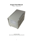
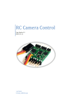
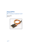
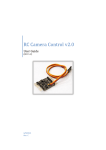
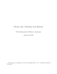
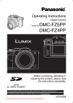
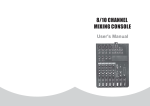
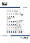
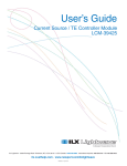
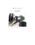
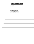
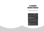
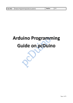
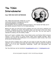
Camera Axe 4.0 User Manual Document Version: 1.0 February 6, 2011 Authors: Andrew Morgan and Maurice Ribble Table of Contents Introduction The Camera Axe is a tool for photographers to trigger cameras or flashes based signals from various sensors. It is useful for catching phenomena that happen too quickly for human reflexes, like photographing a popping balloon or a milk droplet splash. Other uses can be to catch things photographers don't want to wait around for like birds flying to a bird feeder or surveillance of people walking down a hallway. The possibilities are endless. This document describes the operation of the Camera Axe hardware and menus. The Camera Axe 4.0 unit is shown above. This manual describes the operation of the Camera Axe software version 4.0.2. Other versions of the software function similarly but may have some differences in operation. Hardware As shown in the image above, the Camera Axe is housed in a plastic enclosure. The top of the box has a display screen, a number of buttons, a power switch and two LEDs. On the right side of the box are a set of plugs to attach the camera(s) and/or flash(s), up to two sensors and an optional power supply. The Camera Axe is powered by either 6 AA batteries or an optional 9-12 volt power supply. To insert or replace the batteries, remove the four screws in the corner of the box and pull off the top to expose the battery holder inside. The microcontroller used in the Camera Axe is an ATmega328 with the Arduino bootloader installed. Arduino is a common open source platform that makes programming microcontrollers like the Atmega328 easier. For more information about how to load new version of the Camera Axe software or to start making your own modifications visit http://www.cameraaxe.com/wiki/index.php?title=Programming. Display The Camera Axe uses a 2” X 1” LCD capable of displaying 128X64 pixels. This display is used to provide input capability using the menu functions described below and feedback to the user. Power Switch The power switch turns on/off the unit. When the unit is powered on it goes through a startup sequence. In the startup, the microcontroller input and output pins are set up, the default values are loaded from the EEPROM and the display is setup. If the Activate button is depressed during the startup process, the unit will be reset to the factory default values. The system stores changes to parameters in non volatile (static) memory so the settings are saved even when the batteries are removed. Activate Button The activate button turns on/off the monitoring of the sensors. When activated, the unit begins monitoring the sensor status according to the design of the currently shown menu options. This is known as the photo mode. When in photo mode, the other buttons are ignored except where noted below in the descriptions of the menus. Pressing the activate button again de-activates the monitoring and returns the system to the menu mode. In menu mode, the system parameters can be adjusted as described in the Menu sections below. The activate button will also turn off the display, to save power, when in the photo mode if the display is set to turn off in 10 seconds. If the Activate button is depressed during the startup process, the unit will be reset to the factory default values. Page 1 Select Button The select button toggles the edit mode on and off. When in edit mode, the value of individual parameters can be adjusted using the arrow buttons. When not in edit mode, the arrow buttons move from field to field within the current menu. Only one value can be selected/changed at a time. Menu Button The menu button cycles the display between the different menu options. The various menu options are described in detail below. Pressing the menu button also deactivates the edit mode and resets the cursor position to the first item in the next menu. Arrow/Cursor Buttons In edit mode, the left and right button moves the cursor to the previous/next digit in the setting being adjusted. When the up or down button are pressed in the edit mode, the value at the current cursor position is raised/lowered. The numbers will wrap 90 or 09 as needed. Every time a value is changed on the display, it is written to the microcontroller’s static memory. This keeps settings from getting lost when the power is turned off. When not in edit mode, the arrow keys are used to navigate around the display to move from one menu parameter to another. The currently selected parameter is indicated by a flashing value. In general, the way the buttons are used is to use the Menu button to toggle to the desired menu option (described below), then use the Arrow buttons to navigate on the display to the desired setting to change. Once the cursor is on the setting value, the Select button is pressed to enter the edit mode. Once in the edit mode the individual values can be adjusted. The up and down Arrow buttons change the value up/down and the right and left buttons allow selecting the next/previous digit for numerical values. Once the value is at the desired setting/value, the Select button is pressed again to exit the edit mode. From here, the Arrow buttons can be used to navigate to another parameter, if necessary. Once all of the settings have been adjusted as desired, the Activate button is pressed to enter the photo (or trigger) mode. At this point, the sensors are active and a picture can be taken. When done taking images, press the Activate button again to re-enter the menu mode and repeat the process. Camera/Flash LEDs The LED above the Camera/Flash 1 and Camera/Flash 2 labels indicate when the device is triggered. Camera/Flash Ports First two 3.5 mm jacks on the side of the Camera Axe are camera/flash ports. These ports are labeled Camera/Flash 1 and Camera/Flash 2. These ports are used to connect either a camera or flash to be triggered. The Camera/Flash 1 port is used for Device 1 and the Camera/Flash 2 port is for Device 2. The way the Camera Axe triggers cameras and flashes is by allowing current to pass through and the camera provides the voltage. It works like a switch. The camera provides the voltage on one pin and when the Camera Axe lets that voltage pass to another pin the camera triggers. The camera/flash cable configuration is shown below. Page 2 Figure 1 Sensor Ports The other two 3.5 mm jacks on the side of the Camera Axe are sensor ports. These ports are labeled Sensor 1 and Sensor 2. These ports are used to connect a wide variety of sensors to the Camera Axe. Several of the available sensors are described below. The 3.5 mm jack for sensors provides power, ground, and access to an analog pin on the microcontroller. The tip of the 3.5mm plug is +5V, the base of the 3.5 mm plug is ground, and middle of the 3.5 mm plug is the sensor. Note that the analog pin on the microcontroller is not protected so make sure you don't exceed 40mA of current to that pin. Also make sure any input voltages are within the range of 0 to 5 volts. If either of these maximums are exceeded you may damage the microcontroller and it would need to be replaced. Power Port The other port on the side of the box is for connecting an external power supply either in addition to or in place of batteries. Any 6-12 volt power source can be used provided it has the correct connector and polarity. The outside of the plug is ground and the inner part is power. Menus The Camera Axe provides five different sets of menu operations as described below. Based on the pressing of the Activate button, the Camera Axe will either be in the “menu” or “photo” mode. When the Camera Axe is in the menu mode, the various settings can be adjusted according to the description below. When the Camera Axe is in photo mode, the unit is monitoring the sensors and is ready to trigger an image. NOTE: Except for the backlight setting in the General Settings menu, the settings in each menu are independent. For example, the settings in the General Sensor menu do not affect the operation of the Camera Axe when using the Projectile, Valve or Intervalometer menus. Depending on the menu function, there are two different ways that the Camera Axe reads sensor values. • analogRead – this returns an analog value between 0 and 1023 proportional to the sensor voltage of 0 to 5 volts. The Camera Axe displays values from 0 to 999. This is the slower way to read the sensor value (still quite fast at 100 microseconds) but it provides the ability to read the range of values from the sensor. This method is used by the General Sensor menu to allow triggering on a setting or threshold value. • digitalRead – this is the fastest way to read the sensor state, about 15 times faster than the analogRead but it only returns a high (1) or low (0) value. This method is used by the Projectile and Fast Trigger menus. Page 3 General Sensor Menu The general sensor menu is shown in the image below. Due to the display size, the entire menu shown below is not visible at the same time. Pressing the up and down arrows will scroll the display to show the rest of the menu. This is a flexible mode that works well with most sensors. As described above, the select and arrow buttons allow the user to navigate to the different parameters to set up the menu functions. Figure 2 The top area of the menu sets the device settings. Devices are the camera or flash plugged into the ports on the side of the unit. Device1 refers to the Camera/Flash 1 port and Device2 refers to the Camera/Flash 2 port. The bottom area selects the sensor that is associated with a particular device. For understanding how the menu is configured, the menu consists of four sections that work together to configure the device and sensor setting. Each device can be triggered by either (or both) sensor. The upper left section configures device 1, the upper right section configures device 2, the lower left section configures sensor 1 and the lower right configures sensor 2. See the example configurations below for more information on the configuration of this menu. The table below shows the different settings available for each parameter and a brief description of the function of that parameter. Parameter Options Description Trigger Sensor Sensor1 Sensor2 S1_or_S2 S1_and_2 None Delay ms Numeric value between 000.0 and 999.9 Bulb sec Numeric value between 00 and 99 No Yes This setting determines which sensor triggers the device. For example, if Device1 is set with Trigger Sensor = Sensor1 then when sensor 1 is triggered, device 1 will fire. When S1_or_S2 is selected, the device will fire if either sensor is triggered and when S1_and_2 is selected, the device will fire only if both sensors are triggered. The setting of None will turn off triggering of that device. This is the number of millisecond delay between when the sensor is triggered and the device will fire. Using the Select and Arrow buttons allows changing one of the four numeric values at a time until the desired delay is set. The number of seconds that the device will be activated. Prefocus Table 1 – Device Settings Page 4 If set to Yes, the pre-focus pin will be pulled high when the Activate button is pressed, to put the unit into photo mode, causing the camera to pre-focus (if the camera supports this capability). NOTE: Leave this set to No for flashes. Parameter Options Description Trigger Type Low High Threshld Trigger Value Numeric value between 000 and 999. A setting of Low will trigger when the sensor reading is lower than the setting. A setting of High will trigger when the sensor reading is higher than the setting With a Threshld setting, when you activate the sensor it records the base value and then a trigger happens when a difference greater than the threshold value is recorded. Then once the bulb has finished, a new base value is recorded. See the example in the Light Sensor section of the document for how this would be used. First value is the trigger value you set, and second value is the current value read by sensor. The current sensor value, which is displayed to the left of this value, is updated every 500 ms. When set to a trigger type of Threshld, the updating value is the difference between the high and low sensor readings during that sampling period. Power On Off_Sen1 Off_Sen2 This setting allows the designated sensor to be turned off when a sensor is triggered. For example, if there is a laser “sensor” connected to the Sensor 1 port and a light sensor connected to the Sensor 2 port, then setting Sensor2’s Power setting to Off_Sen1 would turn off the laser when Sensor2 was triggered. Table 2 – Sensor Settings An example of using the General Sensor Menu with a microphone is described below in the Microphone Sensor section of the document. Projectile Menu This menu is a special purpose menu for the projectile sensor. The menu parameter settings are described in the table below. Figure 3 Parameter Distance Low/High Trigger Distance Units Page 5 Options Numeric value between 00.0 and 99.9 Low High Inch Cm Comment The distance from the second sensor LED to the position of the projectile when the flash fires. Determines whether to trigger on low or high sensor values. The projectile sensor has high values when nothing is between the sensors so this should be set to a value of Low when using the projectile sensor described below. Set to determine whether the user provided distance is in inches or centimeters. The distance is measured from Sensor 2 to where you want the projectile when the flash fires. Table 3 See the section below for more details and example of how to use this menu with the projectile sensor. Valve Menu This is a special purpose menu for the valve sensor. The menu parameter settings are described in the table below. Figure 4 Parameter Drop1 Size Drop2 delay (ms) Drop2 Size Flash Delay (ms) Options Numeric value between 000 and 999 Numeric value between 000 and 999 Numeric value between 000 and 999 Numeric value between 000 and 999 Comment The number of milliseconds that the valve will be open to release a drop. How long to wait after the first drop to start the second drop The number of milliseconds that the valve will be open to release the second drop. The number of milliseconds to wait after the second drop to trigger the flash. Table 4 To use this menu, plug the valve sensor into Sensor 1 and make sure it is turned on. Plug an external flash into Camera/Flash 1 and plug the camera into Camera/Flash 2 See the section below on the valve sensor for more information on using this menu. Intervalometer Menu This is a menu for taking time series shots. Figure 5 Parameter Page 6 Options Comment Start Delay hours:minutes:seconds Interval hours:minutes:seconds # Shots (0=Inf) Numeric value between 0000 and 9999 Numeric value between 000.0 and 999.9 Numeric value between 0 and 9 Bulb (sec) HDR Stops Mirror Lockup Yes No The start delay determines the time between the activation and the first shot. The amount of time between shots in hours, minutes and seconds. The total number of intervals that will be done. Setting this to 0 will take keep taking shots until this mode is exited or the Camera Axe runs out of batteries. How long the camera/flash will be triggered during each interval. This determines the number of “extra” shots that are taken during an interval. For example, a value of 0 will take one shot during each interval. A value of 2 will take three shots during each interval. The “HDR” is accomplished by doubling the bulb time for each shot (see the example below). This adds another shutter trigger for each shot. To use this your camera must support mirror lockup and have that setting enabled. The camera is triggered to raise the mirror and then two seconds later (to allow the vibration to settle) there is another shutter trigger to take the shot. This works with the camera in mirror lockup mode for cameras that require two shutter presses to take the shot in mirror lockup mode. In this mode, the mirror lockup shutter trigger is ½ second plus the 1.5 second delay. Table 5 An example of how this might be used would be with the following values. Parameter Start Delay Interval # Shots (0=Inf) Bulb (sec) HDR Stops Mirror Lockup Options 00:00:05 00:01:00 2 001.0 3 No Table 6 This would trigger a total of 8 shots. The first one would be after 5 seconds with a 1 second shutter trigger. The 2nd would be about a half second later with a 2 second shutter trigger, the 3rd would have a 4 second shutter trigger and the 4th would have an 8 second shutter trigger. The 5th through 8th shots would start at 1 minute 5 seconds from activation and would have shutter trigger times of 1,2,4,8 seconds respectively. This menu is really only used for taking shots in the dark or with heavy neutral density filters on the lens because the shortest shutter times that can be done (for a 4 shot HDR sequence would be 0.1, 0.2, 0.4 and 0.8 seconds). The reason the minimum granularity 1/10 th of a second is because many cameras don't allow a bulb time of less than this. Fast Trigger Menu This is a more restrictive version of the General Sensor Menu, but gives faster trigger responses because it uses the bitRead method rather than the analogRead method and has a tighter code loop. This menu is only used with Sensor 1 and activates both devices when the sensor is triggered. The devices are activated for 1 second after the delay time. As soon as the sensor is triggered, the sensors are turned off until after the 1 second device activation. Page 7 Some measurements with a scope have shown that the delay for the general sensor mode is about 192 microseconds and the fast trigger mode has a delay of about 40 microseconds. Figure 6 Parameter Delay (ms) Options Numeric value between 000 and 999 Low/High Trigger Low High Comment This is the number of millisecond delay between when the sensor is triggered and the device will fire. Using the Select and Arrow buttons allows changing one of the four numeric values at a time until the desired delay is set. When set to Low, the sensor triggers when the digital bit reads a low (0) value. There is no way to set a specific threshold value since this only registers 0 or 1. When set to High, the sensor triggers when the digital bit reads a high (1) value. Table 7 General Settings Menu The general settings menu allows the backlight to be turned on or off or set to stay on for 10 seconds after the last button press. When the unit is set to turn off the backlight after 10 seconds, pressing the Activate button to enter photo mode will also turn off the backlight. The backlight is the largest contributing factor to power usage on the Camera Axe so turning it off greatly extends battery life. This menu also shows the current version of the software. Figure 7 Parameter Backlight Options On Off 10 sec Comment If On, the backlight stays on all the time, if set to Off, the backlight will be off. If set to 10 sec, the backlight will turn off after 10 seconds with no button press or when the Activate button is pressed. Table 8 PROGRAM NOTE: The countdown timer for turning off the backlight is initially set in the Setup function and is reset if necessary in the detectButtonPress function. Page 8 Sensors There are a wide variety of sensors that can be used with the Camera Axe. Depending on the sensor type and the menu being used, a wide variety of photographs can be taken using the Camera Axe. This section describes the collection of sensors sold with the Camera Axe but any sensor type that conforms to the sensor wiring and electrical requirements will work with the Camera Axe unit. The 3.5 mm jack for sensors provides power (+5V), ground, and access to an analog pin on the microcontroller. The tip of the 3.5mm plug is +5V, the base of the 3.5 mm plug is ground, and middle of the 3.5 mm plug is the sensor. In the 4.0.2 software the sensor pins float instead of using the internal pull-up resistors in the Atmel chip. This basically means that if nothing is plugged into a sensor port the values will not be valid and will change sporadically. If this is a problem, the internal pull-up resistors can be enabled by un-commenting the following two lines in cameraAxe_helperFuncs.c //digitalWrite(SENSOR1_PIN, HIGH); //digitalWrite(SENSOR2_PIN, HIGH); However, this change is not recommended because the pull-up resistors can affect some of the sensors readings. It was better to just not be able trust the values if no sensor is connected than have the pull-up resistors affect the readings. Schematics, part lists and circuit board layouts are available for each of the sensors described below at http://www.cameraaxe.com/wiki/index.php?title=Sensors. This information can be useful for building these and other sensors as needed. Light Sensor The light sensor is used to trigger devices based on changes in the intensity of the light. An example of how the light sensor would be used is described below. Figure 8 As an example of how this sensor might be used with the General Sensor menu described above to record a series of shots as the sun sets the following menu settings could be used. For this use case, the camera would be plugged into the Camera/Flash 1 port and the light sensor would be plugged into the Sensor 1 port. Camera/Flash 2 and Sensor 2 are unused in this example. The values in gray below are ignored and could be anything without affecting this example. Parameter Device 1 Device 2 Trigger Sensor Sensor1 None Page 9 Delay ms Bulb sec Prefocus 000.0 01 No 000.0 00 No Table 9 – Device Settings Parameter Sensor 1 Sensor 2 Trigger Type Trigger Value Power Threshld 10 On Low 000 On Table 10 – Sensor Settings The camera should be set to take a picture using aperture priority to allow the shutter speed to vary as the daylight dims (or however you choose to set up the camera for the shot). These Camera Axe settings will trigger a shot each time the daylight dims by 10 units on the light sensor. The camera will be triggered with no delay for 1 second (but the shutter time will be based on the camera settings), with no additional time for pre-focus. When you start the sensor it records the base value and then a trigger happens when a difference greater than the threshold value is recorded. Then once the bulb has finished a new base value is recorded. This works well for sunsets where you want to take a picture as the light changed gradually. Laser Sensor The laser sensor isn’t really a sensor in that it doesn’t trigger a device but it can be used with the light sensor to create a beam of light that can be broken to trigger the light sensor. When using the General Sensor menu as described above, when the laser is plugged into a sensor port on the Camera Axe, it can be turned off just before triggering the flash to keep the laser light from being in the shot. Figure 9 An example of how the laser sensor could be used would be to trigger a shot when a cat walks though the laser beam in the dark. This could be done with the following settings in the General Sensor menu. For this use case, the camera is plugged into the Camera/Flash 1 port and a flash is plugged into the Camera/Flash 2 port. The light sensor is plugged into the Sensor 1 port and the laser is plugged into the Sensor 2 port. Parameter Device 1 Device 2 Trigger Sensor Sensor1 Sensor 1 Delay ms 000.0 000.2 Page 10 Bulb sec Prefocus 01 No 00 No Table 11 – Device Settings Parameter Sensor 1 Sensor 2 Trigger Type Trigger Value Power Low 100 Off_Sen2 Low 000 On Table 12 – Sensor Settings The camera should be set to manual mode and the aperture and shutter speed should be set as appropriate for the flash value. The delay for Device 2 (the flash) is to allow the shutter on the camera to open before the flash triggers. The Power setting of Off_Sen2 turns the laser off before the camera is triggered to keep the laser beam from being in the shot. The shot will be triggered when the light sensor value goes below 100 (this value may need to be adjusted up or down depending on the sensor reading when the laser is on vs. off the light sensor). Microphone Sensor The microphone sensor is a basic sound activated sensor that is used to trigger devices based on sharp/loud sound changes. An example of how the microphone sensor would be used is described below. Figure 10 Using a microphone sensor plugged into the Sensor 2 port and a flash connected to Camera/Flash 1, the user would like the flash to trigger ½ second after the microphone triggers. The following settings could be used to set this up. In this case the settings for Device1 and Sensor2 are configured according to the table below. Device2 should have the Trigger Sensor set to None and Sensor2 will be ignored. Device1 Parameter Trigger Sensor Options Comment Sensor2 Delay ms 500.0 This setting determines which sensor triggers the device. For example, if Device1 is set with Trigger Sensor = Sensor1 then when sensor 1 is triggered, device 1 will fire. When S1_or_S2 is selected, the device will fire if either sensor is triggered and when S1_and_2 is selected, the device will fire only if both sensors are triggered. The setting of None will turn off triggering of that device. 500ms = ½ second Page 11 Bulb sec 1 The number of seconds that the device will be activated. Sensor2 Parameter Trigger Type Options Comment Low Trigger Value 400 Power On The microphone sensor value goes lower with a loud sound so a Low setting was used in this example. Since the microphone is sending a value that is proportional to the sound level, you could also use this to trigger when the sound level gets quieter (higher value) After plugging in the microphone sensor, watch the value for a few seconds to see what the values are with the ambient noise. This value will vary depending on the microphone sensor and the ambient noise. In this example, the sensor readings were around 500 so a setting of 400 was chosen with a trigger type of low. Not turning off the power to a sensor so leave the power on. Table 13 – Microphone sensor example Projectile Sensor The projectile sensor is used with the projectile menu described above to capture images of projectiles in flight (and objects exploding) at a specific distance from the sensor based on the measured speed of the projectile. Figure 11 The two cables from the projectile sensor are plugged into the Sensor 1 and Sensor 2 ports. Sensor 1 would be the first sensor in the path of the projectile and Sensor 2 would be the second senor as written on the sensor printed circuit board. The flash(s) are connected to the Camera/Flash 1 and/or the Camera/Flash 2 ports. When the unit is in photo mode the code loops watching for the first sensor to be triggered then waits for the second sensor to be triggered. The time between the two sensor events is used to determine the speed of the projectile. This speed is then used to determine the time delay before triggering the flash. When the delay time is reached, device 1 and device 2 are triggered for 1 second. After triggering the devices, and displaying the projectile speed, the unit displays a message saying “Ready for projectile!” and waits for another trigger event on the first sensor. If more than one second passes between detecting the first sensor and the second sensor, without the second sensor being triggered, a message will be displayed that says “Sensor2 did not trigger” and then after 5 seconds, the unit will return to waiting for a projectile. NOTE: This sensor and menu are designed to work with projectiles with a (nearly) constant velocity such as bullets or pellets. The sensor and menu can be used for objects falling through the sensors but due to the effects of gravity, Page 12 the distance value will not be accurate and the user will need to start the drop from the same position each time to get consistent results. NOTE: This menu uses the readSensorDigitalFast method to read the sensor values and depends on the internal processor thresholds to determine if the sensor is high or low. For more information on using the projectile sensor with the Camera Axe see this article: http://diyphotography.net/bullet-photography-at-home Valve Sensor The valve sensor allows taking pictures of droplets of liquid. When used with the valve menu described above, the valve sensor allows taking pictures of up to two droplets at a time including droplet collisions. Figure 12 When connecting the valve sensor you want to plug it into the Sensor1 port on the Camera Axe. To trigger your camera there are two options. The first is to trigger it manually with a fairly long exposure like 5 seconds just before you activate the valve sensor. The second option (and I think this is a little easier) is to connect your camera to the Camera Axe's Camera/Flash 1 port and put your camera's exposure to bulb so the Camera Axe can trigger your camera. You will need to connect one or more flashes to the Camera/Flash 2 port. The valve menu will trigger the camera attached to Camera/Flash 1 port 100ms before triggering the first droplet and will turn off the camera 200 ms after the flash is fired when attached to Camera/Flash 2 port. The rest of the timing is determined by the parameters in the valve menu. To set up the valve menu timing, first determine the time between the first drop and the point where the collision should take place. For example, the image below shows a single drop with a 300ms flash delay. This would be a good position for drop 1 when drop 2 hits it. Here is another shot with a 205ms flash delay. This would be a good position for drop 2 when it hits drop 1. Page 13 If the drop size for drop 1 and drop 2 are both 50, a little math will determine the valve menu settings to produce a two drop collision shot. Take 300ms (from image above) - 205 ms (from image above) - 50 ms (drop 2 size) that is 45ms. Or a different way, take 300ms - 45ms (drop 2 delay) - 50ms (drop 2 size) gives 205ms for the flash delay. Here is a shot taken with Drop1 Size=50, Drop2 Delay=45, Drop2 Size=50, and Flash Delay=205. It may be necessary to play around with the exact timing but this technique will result in some really nice two drop collision pictures. In this example, increasing the flash delay to 215 resulted in an even better picture like this. For more detail on using the Camera Axe with the valve sensor and this example, see the tutorial at http://www.cameraaxe.com/wiki/index.php?title=ValveSensor. Photogate Sensor This photogate sensor, which plugs into either of the Sensor ports on the Camera Axe, detects when something passes through the gate. Great for detecting well aimed bullets, water droplets, or anything that can pass through the 0.4 inch gap. This functions very similar to the light sensor and the laser, but this plugs into a single sensor port and is easier to setup for small objects. Page 14 Figure 13 Motion/Distance Sensor This sensor, which plugs into either of the Sensor ports on the Camera Axe, detects the distance of an object from the sensor. It updates its measurement 20 times per second so won't work for really fast moving objects, but it is ideal for wildlife. Its max distance is about 10 feet (3 meters). The object it is detecting must be the size of a small bird or larger and it is accurate enough to detect a movement of just a few inches. Figure 14 Page 15