1
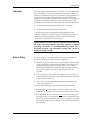
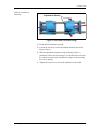
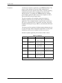
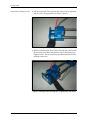
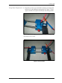
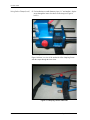
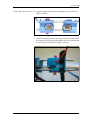
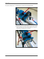
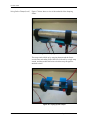
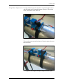
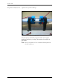
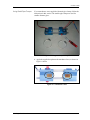
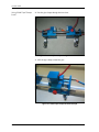
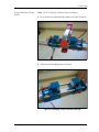
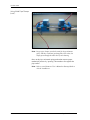
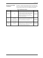
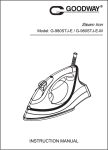
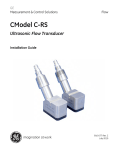
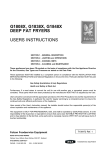
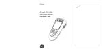
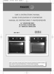
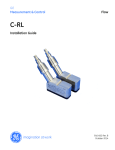
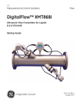
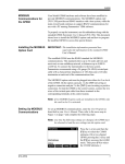
GE
Sensing & Inspection Technologies
Model UTXDR
Panametrics Ultrasonic Flow Transducer
Installation Guide
GE
Sensing & Inspection Technologies
Model UTXDR
Panametrics Ultrasonic Flow Transducer
Installation Guide
916-082A
October 2008
October 2008
Warranty
Each instrument manufactured by GE Sensing, Inc. is warranted to be
free from defects in material and workmanship. Liability under this
warranty is limited to restoring the instrument to normal operation or
replacing the instrument, at the sole discretion of GE. Fuses and
batteries are specifically excluded from any liability. This warranty is
effective from the date of delivery to the original purchaser. If GE
determines that the equipment was defective, the warranty period is:
•
one year for general electronic failures of the instrument
•
one year for mechanical failures of the sensor
If GE determines that the equipment was damaged by misuse,
improper installation, the use of unauthorized replacement parts, or
operating conditions outside the guidelines specified by GE, the
repairs are not covered under this warranty.
The warranties set forth herein are exclusive and are in lieu of
all other warranties whether statutory, express or implied
(including warranties of merchantability and fitness for a
particular purpose, and warranties arising from course of
dealing or usage or trade).
Return Policy
If a GE Sensing, Inc. instrument malfunctions within the warranty
period, the following procedure must be completed:
1. Notify GE, giving full details of the problem, and provide the model
number and serial number of the instrument. If the nature of the
problem indicates the need for factory service, GE will issue a
RETURN AUTHORIZATION number (RA), and shipping instructions
for the return of the instrument to a service center will be
provided.
2. If GE instructs you to send your instrument to a service center, it
must be shipped prepaid to the authorized repair station indicated
in the shipping instructions.
3. Upon receipt, GE will evaluate the instrument to determine the
cause of the malfunction.
Then, one of the following courses of action will then be taken:
•
If the damage is covered under the terms of the warranty, the
instrument will be repaired at no cost to the owner and returned.
•
If GE determines that the damage is not covered under the terms
of the warranty, or if the warranty has expired, an estimate for the
cost of the repairs at standard rates will be provided. Upon receipt
of the owner’s approval to proceed, the instrument will be repaired
and returned.
iii
October 2008
Table of Contents
Introduction . . . . . . . . . . . . . . . . . . . . . . . . . . . . . . . . . . . . . . . . . . . . . . . . . . . . . . . . . . . . . . . . . . . . . . . . . . . . . . . . . 1
Preparing for Installation . . . . . . . . . . . . . . . . . . . . . . . . . . . . . . . . . . . . . . . . . . . . . . . . . . . . . . . . . . . . . . . . . . . . . 1
Choosing an Installation Location . . . . . . . . . . . . . . . . . . . . . . . . . . . . . . . . . . . . . . . . . . . . . . . . . . . . . . . . . 2
Preparing the Pipe. . . . . . . . . . . . . . . . . . . . . . . . . . . . . . . . . . . . . . . . . . . . . . . . . . . . . . . . . . . . . . . . . . . . . . . . 2
Obtaining Transducer Spacing . . . . . . . . . . . . . . . . . . . . . . . . . . . . . . . . . . . . . . . . . . . . . . . . . . . . . . . . . . . . 2
Setting Transducer Spacing . . . . . . . . . . . . . . . . . . . . . . . . . . . . . . . . . . . . . . . . . . . . . . . . . . . . . . . . . . . . . . . 3
Couplants. . . . . . . . . . . . . . . . . . . . . . . . . . . . . . . . . . . . . . . . . . . . . . . . . . . . . . . . . . . . . . . . . . . . . . . . . . . . . . . . 4
Installing the Transducers on the Pipe. . . . . . . . . . . . . . . . . . . . . . . . . . . . . . . . . . . . . . . . . . . . . . . . . . . . . . . . . 5
Using Velcro Straps. . . . . . . . . . . . . . . . . . . . . . . . . . . . . . . . . . . . . . . . . . . . . . . . . . . . . . . . . . . . . . . . . . . . . . . 5
Using Metal Pipe Clamps. . . . . . . . . . . . . . . . . . . . . . . . . . . . . . . . . . . . . . . . . . . . . . . . . . . . . . . . . . . . . . . . . 15
Maintaining the UTXDR Transducers . . . . . . . . . . . . . . . . . . . . . . . . . . . . . . . . . . . . . . . . . . . . . . . . . . . . . . . . . 19
Specifications. . . . . . . . . . . . . . . . . . . . . . . . . . . . . . . . . . . . . . . . . . . . . . . . . . . . . . . . . . . . . . . . . . . . . . . . . . . . . . . 20
v
October 2008
Introduction
The Model UTXDR clamp-on ultrasonic flow transducer for liquids is
used exclusively with the GE Sensing line of ultrasonic flowmeters
(see Table 1 below). These transducers measure the flow rate of
sonically-conductive liquids through pipes having diameters from
0.5 in. (1.3 cm) to 8 in. (20.3 cm). Such measurements are typically
independent of the pipe material. Figure 1 below shows a typical
UTXDR transducer assembly.
Table 1: UTXDR Application Information
Flowmeter Model
Cable Type
Clamp Type
UTX878
3C
Metal
DF868, XMT868 & AT868
2C
Metal
PT878
LM
Velcro
Figure 1: UTXDR Transducer Assembly
Preparing for Installation Before the clamping fixture and transducers can be properly installed:
•
Choose an installation location.
•
Prepare the pipe.
•
Obtain the transducer spacing.
Caution!
A flowmeter’s accuracy and performance depends on
the location, spacing, and alignment of the transducers.
The transducer spacing is unique to your installation.
Installing UTXDR Transducers
1
October 2008
Choosing an Installation
Location
Locate the transducer measurement point at least 3 ft (1 m) from any
butt welds or flanges. Ideally the location would be in the center of a
20 ft (6 m) section of straight pipe. Make sure there is 6 in. (15 cm)
clearance on both sides of the pipe for easy transducer installation.
Note: To guarantee the specified accuracy of the flowmeter, a
straight section of pipe and a fully-developed flow profile are
highly recommended. However, if such conditions are not
possible, the transducer location should be such that the
acoustic signal travels through the full distribution of the
under-developed flow profile for best repeatability.
Preparing the Pipe
To prepare the pipe for transducer installation, complete the following
steps:
1. Remove any rust and paint from an area 2 in. (5 cm) wide by 12 in.
(30 cm) long on one side of the pipe.
2. Polish the cleaned area, taking care to preserve the original
curvature of the pipe.
3. With an ultrasonic thickness gage, measure the pipe thickness at a
minimum of six spots on the cleared area. Take at least three
measurements at each spot to ensure accuracy. The thickness
readings should not vary by more than 5% at each spot. If you
encounter more than a 5% variation at each spot, try a different
section of the pipe. Verify that the wall thickness at both
transducer locations has less than the 5% variation.
4. Measure the outside diameter (OD) of the pipe using a tape
measure or the supplied pipe wrap.
Obtaining Transducer
Spacing
Before installing the clamping fixture, you must obtain the transducer
spacing from the flowmeter. You will need to know the transducer
spacing later in this procedure.
To obtain the spacing, you must enter the measured OD and the
average pipe wall thickness into the flowmeter’s user program (Pipe
Parameters) to determine the transducer spacing. Refer to your
flowmeter User’s Manual or Startup Guide for more details, and for
instructions on navigating to the programming screen for the
transducer spacing.
2
Installing UTXDR Transducers
October 2008
Setting Transducer
Spacing
Adjustment Screws
Figure 2: The UTXDR Transducer Design
To set the desired transducer spacing:
1. Loosen the red screws on the adjustable transducer (shown in
Figure 2 above).
2. Slide the adjustable transducer on the rails until you have
positioned it at the desired spacing. Use the ruler on the rails and
the white tick mark on the transducer housing to assist in setting
the correct spacing.
3. Tighten the red screws to secure the transducer to the rails.
Installing UTXDR Transducers
3
October 2008
Couplants
An ultrasonic couplant is supplied for your UTXDR installation. The
purpose of the couplant is to provide reliable transmission of
ultrasound between two adjacent solid surfaces. Generally speaking,
couplants perform this task by excluding air from between the
adjacent surfaces. Accordingly, the UTXDR transducers should be
pressed tightly against the pipe to squeeze the couplant to as thin a
film as practical for the given pipe surface.
The most commonly used couplants in ultrasonic testing are
ordinarily satisfactory for any short-term clamp-on flowmeter
application. These couplants include, in general order of preference:
gels, grease, propylene glycol, oil, glycerine, and water. Long-term
couplants include grease, epoxy adhesive, and solid rubber-like sheet
couplant.
The factory provides couplants for both permanent and temporary use
as well as for high- and low-temperature applications. For long-term
installations, make sure the couplant does not dry or run out.
Standard couplants supplied by GE are listed in Table 2 below.
Table 2: Couplants
PART NO.
CPL-1
TYPE
Standard
TEMP. RANGE
CPL-2
High/Low
Temperature
-256 to 500oF
(-160 to +260oC)
Semi-Permanent
CPL-3
For Portable
Temporary
CPL-4
Special
-4 to 140oF
(-20 to +60oC)
As Required
CPL-7
Epoxy
o
-40 to 149 F
(-40 to +65oC)
14 to 122oF
(-10 to +50oC)
USE
Semi-Permanent
*Difficult
Applications
Permanent
Permanent
-40 to 446oF
(-40 to +230oC)
* Installations involving hotter or colder temperatures than listed above,
may require special couplants. Consult the factory for such applications.
CPL-8
4
Solid Sheet
Installing UTXDR Transducers
October 2008
Installing the
Transducers on the Pipe
Using Velcro Straps
Proceed to the appropriate section for your transducers:
•
Velcro straps - below
•
Metal clamps - page 15
If your transducers are supplied with velcro straps, follow the
instructions in this section.
Figure 3: Clamping Fixture with Loose Straps
1. Use an allen wrench to loosen the set screws on each side of one of
the housings and slide one of the rails forward (see Figure 4
below).
Figure 4: Loosening the Set Screws
Installing UTXDR Transducers
5
October 2008
Using Velcro Straps (cont.)
2. Slip the looped end of the strap into the slot area. Be sure the hook
and pile side is facing upwards (see Figure 5 below).
Figure 5: Inserting the Velcro Strap
3. Slide the rail through the looped end of the strap and continue until
the end of the rail is flush with the back edge of the housing (see
Figure 6 below). This is critical for proper measurements off of the
markings on the rails.
Figure 6: Sliding the Rail through the Looped End of the Strap
6
Installing UTXDR Transducers
October 2008
Using Velcro Straps (cont.)
4. Repeat the previous step on the other housing by loosening both
thumb screws and sliding the housing back (see Figure 7 below).
Again, remember to keep the hook and pile side facing upwards.
Figure 7: Sliding the Other Rail through the Strap
The straps are now secure.
Figure 8: Secure Straps
Installing UTXDR Transducers
7
October 2008
Using Velcro Straps (cont.)
5. For installation on small diameter pipes (1½” and smaller), slip the
straps through the inner slot closest to the strap (see Figure 9
below).
Figure 9: Installation on Small Diameter Pipes
Figure 10 below is a view of the underside of the clamping fixture
with the straps through the inner slots.
Figure 10: Clamping Fixture Underside
8
Installing UTXDR Transducers
October 2008
Using Velcro Straps (cont.)
6. Apply the supplied couplant to the transducer faces, as shown in
Figure 11 below.
Figure 11: Transducer Faces
7. Position the clamping fixture on the pipe and slip the strap around
the bottom of the pipe and up through the other inner slot towards
the inside of the second rail (see Figure 12 below).
Figure 12: Positioning the Clamping Fixture on the Pipe
Installing UTXDR Transducers
9
October 2008
Using Velcro Straps (cont.)
8. Flip the strap over the top of the rail and pull taught.
Figure 13: Tightening the Strap
9. Bring the strap back around the bottom of the pipe and secure the
strap to itself. Be sure the strap remains taught as it is secured to
firmly hold the clamping fixture on the pipe.
Figure 14: Securing the Strap to Itself
10
Installing UTXDR Transducers
October 2008
Using Velcro Straps (cont.)
10.Repeat Steps 7, 8 and 9 on the other half of the clamping fixture.
Figure 15: Securing the Other Half
The straps are now secure.
Figure 16: Secure Straps
Installing UTXDR Transducers
11
October 2008
Using Velcro Straps (cont.)
Figure 17 below shows a view of the underside of the clamping
fixture.
Figure 17: Clamping Fixture Underside
The straps can be tidied up by wrapping them around the fixture
several times and ending with a half twist, followed by a single wrap
around, and then another half twist so that the strap can again be
attached to itself.
Figure 18: Tidying Up the Straps
12
Installing UTXDR Transducers
October 2008
Using Velcro Straps (cont.)
For larger diameter pipes, the strap does not pass through the inner
slot, but simply passes around the bottom of the pipe. Then it slips
under, around and over the other rail.
Figure 19: Wrapping the Strap on Larger Diameter Pipes
The strap then wraps around the bottom of the pipe again and secures
back onto itself.
Figure 20: Securing the Strap on Larger Diameter Pipes
Installing UTXDR Transducers
13
October 2008
Using Velcro Straps (cont.)
Again, the straps can be tidied up.
Figure 21: Tidying Up the Straps
Once on the pipe, an internal spring mechanism ensures proper
mechanical pressure by “pressing” the transducer face against the
pipe surface.
Note: Refer to your flowmeter User’s Manual or Startup Guide to
wire the transducers.
14
Installing UTXDR Transducers
October 2008
Using Metal Pipe Clamps
If your transducers were supplied with metal pipe clamps, follow the
instructions in this section. The smaller pipe clamps are used for
smaller diameter pipes.
Figure 22: Using Metal Pipe Clamps
1. Apply the supplied couplant to the transducer faces, as shown in
Figure 11 below.
Figure 23: Transducer Faces
Installing UTXDR Transducers
15
October 2008
Using Metal Pipe Clamps
(cont.)
2. Pass the pipe clamps through the inner slots.
Figure 24: Metal Pipe Clamps Through the Inner Slots
3. Affix the pipe clamps around the pipe.
Figure 25: Metal Pipe Clamps Around the Pipe
16
Installing UTXDR Transducers
October 2008
Using Metal Pipe Clamps
(cont.)
Note: Use of a temporary clamp facilitates installation.
4. Use a nut driver to tighten the pipe clamps (see Figure 26 below).
Figure 26: Tightening the Metal Pipe Clamps
5. Fully secure the clamping fixture to the pipe.
Figure 27: Clamping Fixture Secured to the Pipe
Installing UTXDR Transducers
17
October 2008
Using Metal Pipe Clamps
(cont.)
Figure 28: Another View
Note: Larger pipe clamps can also be used for larger diameter
pipes, and they would not go through the inner slots, but
simply pass through the main slot of each housing.
Once on the pipe, an internal spring mechanism ensures proper
mechanical pressure by “pressing” the transducer face against the
pipe surface.
Note: Refer to your flowmeter User’s Manual or Startup Guide to
wire the transducers.
18
Installing UTXDR Transducers
October 2008
Maintaining the UTXDR
Transducers
Transducers, couplant, and the clamping fixture are provided by the
factory. Once you have completed the installation, little maintenance
is required. Refer to Table 3 below for maintenance information.
Table 3: Maintenance Checks
Component
Transducer
Couplant
Interval
Maintenance Check
Comments
N/A
No additional adjustments or maintenance is
needed. If you suspect something is wrong with a
transducer and/or you need to replace it, simply
remove the clamps that secure the transducer
assembly in place and remove it. Refer to
Installing the Transducers on the Pipe on page 5
to insert a new transducer.
No cleaning
is required.
Verify every 6 months in Measure the signal strength using the flowmeter
diagnostics and compare it to the value taken at
dry areas
the time of installation. Good and bad limits are
(e.g. the desert).
Verify every 12 months listed in the flowmeter User’s Manual.
No cleaning
is required.
in other areas.
Clamping
Fixture
Determined
by user
Installing UTXDR Transducers
Periodic inspection and tightening of the
clamping fixture nuts is required to ensure the
clamping fixture does not become loose and fall
from the pipe, possibly causing injury.
No cleaning
is required.
19
October 2008
Specifications
Table 4: UTXDR Transducer Specifications
Parameter
Transducer #
407
408
Intended Uses
Small pipes; High performance
Installation Type
Clamp-on for liquid applications
Material
316 Stainless Steel, aluminum and plastic
Pipe Sizes
2” to 8” (5 to 20 cm) 0.5” to 2” (1 to 5 cm)
diameter
diameter
Operating Frequency
2 MHz
4 MHz
Electrical Rating
200 V peak-to-peak, 5 mA
Ambient Temperature Range
–4° to 140°F (–20° to 60°C)
Process Temperature Range
–4° to 140°F (–20° to 60°C)
North American Certification
- Weatherproof
European Certification
- Weatherproof
IP65, Type NEMA 4
IP65
IMPORTANT: The transducer is protected by a suitable fuse located in the
flowmeter electronics. The fuse has a breaking capacity in
accordance with the short circuit current of the supply.
20
Installing UTXDR Transducers
USA
1100 Technology Park Drive
Billerica, MA 01821-4111
Web: www.gesensing.com
Ireland
Sensing House
Shannon Free Zone East
Shannon, County Clare