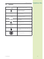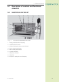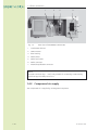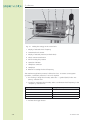
1
Operating Manual
MASTERPULS® MP100 VET
for veterinary medicine
Published October, 2011
Original language: German
STORZ MEDICAL AG
Lohstampfestr. 8
CH-8274 Tägerwilen
Switzerland
20519
»elite edition +«
11 331 02 1011
1-1
blank page
1-2
11 331 02 1011
Table of Contents
1
General Information
1.1
Introduction
1.1.1
Indications . . . . . . . . . . . . . . . . . . 1-5
1.1.2
Contraindications
.
.
.
.
.
.
.
.
.
.
.
.
.
.
.
. 1-6
1.1.3
Side effects .
.
.
.
.
.
.
.
.
.
.
.
.
.
.
.
. 1-6
1.2
Symbols
1-7
1.3
Prerequisites for operating the MASTERPULS MP100 VET
1-8
1.3.1
Operator . . . . . . . . . . . . . . . . . . . 1-8
1.3.2
Training of the operator
1.4
Description of controls and functional elements
1.4.1
MASTERPULS MP100 VET . . . . . . . . . . . . . . 1-9
1.4.2
Compressed air supply . . . . . . . . . . . . . . 1-10
2
Installation Instructions
2.1
Unpacking
2-3
2.2
Scope of supply
2-3
2.3
Installation
2-4
2.3.1
Handpiece holder installation . . . . . . . . . . . . . 2-4
2.3.2
Connecting the power supply cables . . . . . . . . . . 2-5
2.3.3
Potential equalisation
2.3.4
Handpiece connection . . . . . . . . . . . . . . . 2-6
3
Operation
3.1
General warnings and safety information
3-3
3.2
Start-up
3-7
3.3
Functional checks
3-9
3.4
Standard settings
3-9
3.5
Treatment
3-10
3.6
Info menu
3-12
3.7
Resetting the handpiece shock counter
3-13
4
Cleaning, Maintenance, Overhaul
4.1
Cleaning
4-3
4.2
Fuse replacement
4-4
4.3
Emptying the condensate collector
4-5
4.4
Replacing the filter element
4-6
4.5
Maintenance
4-8
11 331 02 1011
1-3
.
.
.
.
.
.
.
.
.
.
.
.
.
.
. 1-8
1-9
. . . . . . . . . . . . . . . 2-5
1-3
1-4
4.6
Disposal
4-8
4.7
Repair
4-8
4.8
Service life
4-8
5
Status messages and Trouble-shooting
5.1
Warnings
5-3
5.2
Trouble-shooting
5-5
6
Accessories and Spare Parts
6.1
MASTERPULS MP100 VET
6-3
6.2
Accessories
6-3
6.3
Documentation
6-3
7
Technical Specifications
7.1
MASTERPULS MP100 VET
7-3
7.2
Nameplate
7-4
7.3
Conformity with directives
7-4
7.4
Conformity with standards
7-5
8
Warranty and Service
8.1
Warranty
8.1.1
Warranty for the control device
. . . . . . . . . . . . 8-3
8.1.2
Warranty for the handpiece .
.
8.2
Service
8-3
.
.
.
.
.
.
.
.
.
.
. 8-3
8-3
11 331 02 1011
1 – General information
General Information
11 332 02 1011
1
1-1
1 – General information
blank page
1-2
11 332 02 1011
1 – General information
1.1
Introduction
This manual contains warnings, safety instructions and specific operating instructions in accordance with liability regulations.
DANGER !
Refers to a situation of acute danger which, if not
avoided, could lead to serious or fatal injury.
WARNING !
Refers to a situation of potential danger which, if
not avoided, could lead to serious or fatal injury.
CAUTION !
Refers to a situation of potential danger which, if
not avoided, could lead to minor injury.
ATTENTION
Warns against possibly harmful situations that could lead to damage to
either the product or to the surrounding area.
NOTE
Additional information concerning specific features or operating instructions is
preceded by the term "NOTE".
11 332 02 1011
1-3
1 – General information
CAUTION !
Before using the MASTERPULS MP 100 VET for the
first time, please ensure that you have read and
understood all the information provided in this
operating manual.
Familiarity with the information and instructions
contained in this manual is essential for ensuring
efficient and optimal use of the instrument, for
avoiding hazards to personnel and equipment
and for obtaining good treatment results.
Thorough knowledge of the information included in this manual will also enable you to react
promptly and effectively in the event of malfunctions and errors.
When using optional accessories, please also refer
to the separate operating manuals for each of
these accessories. It is imperative that users be
familiar with the content of this manual before
operating any part of this system.
The MASTERPULS MP 100 VET is a compressed air-operated ballistic shock wave
generator. The shock waves in the MASTERPULS MP 100 VET are generated with a
precision ballistic mechanism in the handpiece. A projectile is accelerated by compressed air. The motion and weight of the projectile produces kinetic energy. When
the projectile impacts against an immovable surface, the shock transmitter, this
kinetic energy is converted into sound energy. This acoustic pulse is transmitted into
the tissue to be treated either directly or via an acoustic impedance adapter with the
help of a gel.
Physically speaking, these are radial pressure waves. The applied pressure pulse propagates radially within the tissue and has a therapeutic effect on areas of the tissue
near the surface, in particular.
NOTE
Medical devices operating on the basis of the above principle are generally
referred to as extracorporeal shock wave systems in modern medical literature.
1-4
11 332 02 1011
1 – General information
1.1.1 Indications
The MASTERPULS MP100 VET is a compact radial shock wave therapy system. Indications include:
For horses
–– Insertion desmopathies
Suspensory ligament origin
Suspensory ligament insertion/sesamoid bones
Insertion desmopathy of the cunean tendon
Collateral ligaments on various joints
Lig. nuchae
–– Tendopathy/desmopathies
Chronic tendinitis
Fibrosis and adhesions
Thickening of the annular ligament
Desmitis of the suspensory ligaments
Calcifications of the tendons or ligaments
Metaplasia/myopathies
–– Arthroses
Pastern joint arthroses
Bone spavin
Pain therapy for acute arthroses
–– Osteoporoses
Sesamoid bones
Navicular bone
–– Pseudarthroses
–– Back pain
–– Acupuncture
Qualified training in acupuncture and acupuncture shock wave therapy (AkuST) is
required for therapeutic application of the MASTERPULS MP100 VET in the field of
acupuncture.
–– Muscle trigger points
A sound knowledge of trigger point therapy and trigger point shock wave therapy
(TrST) is required for therapeutic application of the MASTERPULS MP100 VET in the
field of trigger point shock wave therapy.
11 332 02 1011
1-5
1 – General information
For small animals, predominantly dogs
–– Fractures/fissures
–– Illnesses of tendons and tendon sheaths
–– Hip dysplasia
–– Osteopathy
–– Legg-Calvé-Perthes syndrome
–– Degenerative joint diseases
–– Chips
1.1.2 Contraindications
CAUTION !
The contraindications listed here are examples.
No claims are made regarding the completeness
or unlimited validity of this list of contraindications.
Treatments with the STORZ MEDICAL MASTERPULS MP100 VET are not permitted
in the following cases:
–– Pregnancy
–– Animals in growth
–– Cortisone therapy up to 6 weeks before first treatment
CAUTION !
Shock waves must not be applied to target areas
located above air filled tissue (lungs), nor to any
regions near large nerves, vessels, the spinal column or head (except in the facial area).
1.1.3 Side effects
Treatment with the MASTERPULS MP100 VET may cause the following side effects:
–– Swelling, haematomas
–– Petechiae
These side effects generally abate after a few days.
1-6
11 332 02 1011
1 – General information
1.2
Symbols
Please read the operating manual!
Application unit of type B
according to IEC 60601 - 1
Potential equalisation
R-SW handpiece connector
USB connector
CSA certification mark
WEEE label
IPX1: Protection against dripping water (vertically
falling drops)
Wear hearing protection!
11 332 02 1011
1-7
1 – General information
1.3
Prerequisites for operating the
MASTERPULS MP100 VET
1.3.1 Operator
The MASTERPULS MP100 VET is intended exclusively for use by veterinary specialists
and is only allowed to be used by qualified and instructed personnel.
Such a specialist is expected to have practical knowledge of veterinary procedures and applications as well as of the terminology, and should be experienced in
treating the indications stated in Chapter 1.1.1 Indications. The specialist must have
the basic physical and cognitive prerequisites such as vision, hearing and reading.
Furthermore, the basic functions of the upper extremities must be guaranteed.
The instrument is designed for a demographic target group between 18 and 65
years.
1.3.2 Training of the operator
Operators of the MASTERPULS MP100 VET must have been adequately trained in
using this system safely and efficiently before they operate the instrument described
in this handbook. An introduction to the principles of operation will be provided by
your STORZ MEDICAL dealer with reference to this operating manual and will be
documented in the system logbook.
The operator must be instructed in the following points:
–– Instruction in the operation and designated use of the instrument with practical exercises
–– Mechanism of action and function of the instrument and the energies delivered by it
–– All component settings
–– Indications for use of the instrument
–– Contraindications and side effects of the therapy waves
–– Explanation of the warning notes in all operating statuses
–– Instruction in how to perform the functional checks
Further training requirements vary from country to country. It is the operator's responsibility to ensure that the training meets the requirements of all applicable local
laws and regulations. Further information on training in the operation of this system
is available from your STORZ MEDICAL dealer. However, you can also contact the
following address directly:
STORZ MEDICAL AG
Lohstampfestrasse 8
Postfach
CH-8274 Tägerwilen
Switzerland
1-8
Telephone: +41 (0) 71 677 45 45
Fax: +41 (0) 71 677 45 05
11 332 02 1011
1 – General information
1.4
Description of controls and functional
elements
1.4.1 MASTERPULS MP100 VET
4
5
6
7
8
3
2
9
1
Fig. 1-1  Front view of MASTERPULS MP100 VET
1 Display of selected shock frequency
2 Treatment shock counter
3 Display of selected pressure (nominal value)
4 Shock counter reset button
5 Dial for setting the pressure
6 Operation indicator
7 Handpiece connector
8 Handpiece
9 Buttons for setting the shock frequency
11 332 02 1011
1-9
1 – General information
1
2
3
4
5
6
7
Fig. 1-2
Rear view of MASTERPULS MP100 VET
1 Condensate collector
2 USB connector
3 Filter housing
4 Mains switch
5 Mains fuse holder
6 Mains connector
7 Potential equalisation connector
NOTE
The USB connector (Fig.1 – 2/2) is only suitable for connecting a USB memory
stick that supports USB protocol V1.1.
1.4.2 Compressed air supply
The compressed air is supplied by an integrated compressor.
1-10
11 332 02 1011
2 – Installation instructions
Installation Instructions
2
11 333 02 0510
2-1
2 – Installation instructions
blank page
2-2
11 333 02 0510
2 – Installation instructions
2.1
Unpacking
• Remove the instrument and accessories from the packaging container. Proceed
with extreme caution.
• Check that all items are included in the packaging container and that they are
not damaged.
• Contact your supplier or the manufacturer immediately if any items are missing
or damaged.
• Retain the original packaging. It may prove useful for any later equipment
transport.
2.2
Scope of supply
The standard scope of supply of the STORZ MEDICAL MASTERPULS MP100 VET
includes the following items:
–– MASTERPULS MP100 VET (control system)
–– Mains cable (EU / USA)
–– Gel bottle
–– User manual (operating manual, system logbook and training records)
–– R-SW handpiece set
–– Handpiece holder, complete
Please refer to Chapter 6 Accessories
accessories.
11 333 02 0510
and
Spare Parts for information on optional
2-3
2 – Installation instructions
2.3
Installation
2.3.1 Handpiece holder installation
• The handpiece can be fitted to the right or to the left side of the instrument as
desired by the system user (Fig. 2-1).
Fig. 2-1 Location of the bores provided on both side panels
• Remove the holders and associated screws from the packaging container.
• Mount the handpiece holder as shown in Fig. 2-2.
Fig. 2-2 Position of the handpiece holder
2-4
11 333 02 0510
2 – Installation instructions
2.3.2 Connecting the power supply cables
• Connect the supplied mains cable to the mains connector (Fig. 2-3/1) on the
rear of the instrument.
1
Fig. 2-3 Connecting power supply cables
• Insert the mains plug into the socket.
Attention
When setting up the instrument, make sure that the air outlets on the
housing of the MASTERPULS MP100 VET are not blocked.
The instrument must only be connected to properly earthed and correctly installed shockproof sockets!
2.3.3 Potential equalisation
The MASTERPULS MP100 VET features a potential equalisation connector
Fig. 1-2/7).
Where necessary, connections for potential equalisation must be made by suitably
qualified personnel.
CAUTION !
The potential equalisation connector of the MASTERPULS MP100 VET must be connected in accordance with the relevant national regulations.
11 333 02 0510
2-5
2 – Installation instructions
2.3.4 Handpiece connection
• Connect the plug of the handpiece to the handpiece connector (Fig. 2-4) of
the MASTERPULS MP100 VET.
Fig. 2-4 Handpiece connector
• Make sure that the red spots on the connector match the red spots on the
handpiece connector (Fig. 2-5).
Fig. 2-5 Connecting the handpiece
• Place the handpiece into the handpiece holder.
NOTE
Please also refer to the separate operating manual of your handpiece.
2-6
11 333 02 0510
3 – Operation
Operation
11 334 02 1011
3
3-1
3 – Operation
blank page
3-2
11 334 02 1011
3 – Operation
3.1
General warnings and safety information
CAUTION !
The transport bag is provided only to transport
the device. If the device is left in the transport bag
during treatment, the device becomes hot, due to
lack of ventilation.
Burns, conflagration and damages of the device are
possible.
• Take the device out of the transport bag during
treatment.
ATTENTION
Transport the device in the transport bag only when the condensate
collector is empty. Otherwise the water can run into the device.
11 334 02 1011
3-3
3 – Operation
CAUTION !
The MASTERPULS is exclusively intended for use by
medical specialists and must only be used by suitably qualified and trained medical personnel. See also
Chapter 1.3 Prerequisites for operating the MASTERPULS MP100 VET.
The user is responsible for correctly positioning the
handpieces of the MASTERPULS.
Correct determination of the location of the treatment zone is the responsibility of the user.
Only perform treatments approved by STORZ MEDICAL AG!
To avoid safety hazards, use of the instrument for
applications other than those specified in Chapter
1.1.1 Indications is not allowed!
Do not use the MASTERPULS in potentially explosive environments, i.e. in the presence of a flammable anaesthetic mixture with air or with oxygen or
nitrous oxide.
The MASTERPULS has a potential equalisation connector. This must be connected in accordance with
the relevant national regulations.
Cleaning agents and disinfectants can form an
explosive atmosphere. Disconnect the MASTERPULS
from the mains before starting any cleaning or
overhaul work!
Do not try to open the instrument! Risk of electric
shocks!
Disconnect the handpiece from the instrument
before carrying out cleaning and maintenance work
and do not reconnect it until it has been completely
reassembled!
Risk of transmission of microorganisms!
Clean the handpiece after each use!
Refer to Chapter 4.1 Cleaning for details.
3-4
11 334 02 1011
3 – Operation
ATTENTION
Check that the installation surfaces have sufficient carrying capacity to
avoid equipment damage!
Electric medical devices underlie special regulations regarding Electromagnetic Compatibility (EMC). Hence, medical electric devices have to
be installed and commissioned in accordance with the EMC guidelines
detailed in the accompanying documents.
Portable and mobile HF communications equipment (such as cell phones) may cause interferences with medical electric devices.
The use of accessories or cabling not authorised by the manufacturer
may cause increased emissions or may lead to reduced interference
resistance of the device.
The MASTERPULS is not allowed to be positioned immediately next
to or stacked with other devices. If the operation near or jointly with
other devices is required, the MASTERPULS has to be tested against
that particular environment to ensure operation according to technical
specification. The MASTERPULS is allowed to be positioned and operated close to the listed accessories.
The instrument must only be connected to properly earthed and correctly installed shockproof sockets!
Check that the instrument is in perfect working order before each use,
see Chapter 3.3 Functional checks.
Never cover the instruments when in use!
Make absolutely sure that no liquid can seep into the system housing
or handpiece.
Any damage to the instrument resulting from incorrect operation is not
covered by the manufacturer's warranty.
Disposal of the instrument and its components must be carried out in
accordance with national waste disposal regulations.
The MASTERPULS must only be used with accessories that have been
approved by the system manufacturer. For safety reasons, unauthorised system modifications are not permitted. This will void the CE
mark approval and warranty.
11 334 02 1011
3-5
3 – Operation
NOTE
The MASTERPULS MP100 VET corresponds to the requirements of the applicable standards on electromagnetic compatibility (EMC) EN60601-1-2.
These limits are designed to provide reasonable protection against harmful
interference in a typical medical installation. The instrument described here generates and uses high-frequency energy and can emit the same. If not installed
and used in accordance with these instructions, the instrument may cause
harmful interference to other devices in the vicinity. However, there is no guarantee that interference will not occur in a particular installation. If this product
does cause harmful interference with other devices, which can be determined
by turning the instrument off and on, the user is encouraged to try to correct
the interference by one or more of the following measures:
• Reorient or relocate the receiving device.
• Increase the distance between the devices.
• Connect the devices into an outlet on a circuit different from that to which the
other device is connected.
• Consult the manufacturer or field service technician for help.
3-6
11 334 02 1011
3 – Operation
3.2
Start-up
NOTE
Prior to start-up, please refer to the separate operating manual of your handpiece.
• Switch on the MASTERPULS MP100 VET at the mains switch on the rear of the
instrument (Fig. 1-2/4).
Once the instrument has been started, the display automatically shows the last
shock frequency setting. The display flashes.
• To confirm the existing setting, press one of the two arrow keys.
• To change the existing setting, press one of the two arrow keys.
As soon as the display has stopped flashing, the selected shock frequency can be
increased or reduced using the arrow keys.
With the MASTERPULS MP100 VET, the shock wave frequency can be selected in
steps.
operating mode
energy/frequency
R-SW
4 bar/21 Hz
R-SW
5 bar/12 Hz
V-ACTOR
4 bar/21 Hz
V-ACTOR
3 bar/31 Hz
• Set the energy of the shocks using the dial (Fig. 3-1/5) to an initial value
of 1.5 bar.
The value is shown on the pressure display (Fig. 3-1/3).
11 334 02 1011
3-7
3 – Operation
4
5
6
7
8
3
2
9
1
Fig. 3-1 Setting the energy on the control unit
1 Display of selected shock frequency
2 Treatment shock counter
3 Display of selected pressure (nominal value)
4 Shock counter reset button
5 Dial for setting the pressure
6 Operation indicator
7 Handpiece connector
8 Handpiece
9 Buttons for setting the shock frequency
The maximum application pressure is limited to 5 bar. To ensure correct system
operation, a minimum pressure of 1.0 bar is required.
• For working in single shock mode, select the “-” symbol (dash) in the “Frequency” selection box.
• To work in continuous shock mode, select a continuous shock frequency in the
“Frequency” selection box.
operating mode
energy/frequency
R-SW
4 bar/21 Hz
R-SW
5 bar/12 Hz
V-ACTOR
4 bar/21 Hz
V-ACTOR
3 bar/31 Hz
• Activate the trigger button.
3-8
11 334 02 1011
3 – Operation
3.3
Functional checks
Perform the following functional checks after the instrument has been installed:
• Check the control unit and handpiece for damage.
• Take the MASTERPULS MP100 VET into operation (Chapter 3.2 Start-up).
• Set the pressure to 1.5 bar.
• Reset the treatment shock counter (Fig. 3-1/2) with the reset button
(Fig. 3-1/4) on the front of the instrument.
• Release individual shocks in single shock mode.
• Release shocks in continuous shock mode (shock frequency 1 Hz and 21 Hz).
• Check that the triggered shocks are correctly counted on the treatment shock
counter on the front of the instrument.
• Set the pressure to maximum 4 bar.
• Release individual shocks in single shock mode.
• Release shocks in continuous shock mode (shock frequency 1 Hz and 21 Hz).
• Test the other frequencies as follows:
operating mode
energy/frequency
R-SW
4 bar/21 Hz
R-SW
5 bar/12 Hz
V-ACTOR
4 bar/21 Hz
V-ACTOR
3 bar/31 Hz
3.4
Standard settings
• Before each treatment, set the treatment shock counter (Fig. 3 – 1/2) on the
control unit to zero by pressing the reset button (Fig. 3-1/4).
Treatment should always start at a low energy level. This also applies to resuming
treatment after an interruption.
• Select a low energy level.
11 334 02 1011
3-9
3 – Operation
3.5
Treatment
CAUTION !
The transport bag is provided only to transport
the device. If the device is left in the transport bag
during treatment, the device becomes hot, due to
lack of ventilation.
Burns, conflagration and damages of the device are
possible.
• Take the device out of the transport bag during
treatment.
ATTENTION
Transport the device in the transport bag only when the condensate
collector is empty. Otherwise the water can run into the device.
CAUTION!
Always read Chapter 3.1 General warnings and
ty information before beginning treatment.
safe-
Please also follow the instructions in the separate
operating manual for your handpiece.
Each time after the instrument has been transported, make sure that all functional checks have
been performed on the instrument before you start
treatment.
Only perform treatments approved by STORZ MEDICAL AG!
To avoid safety hazards, use of the instrument for
applications other than those specified in Chapter
1.1.1 Indications is not allowed!
All status and error messages signaled during treatment must always be attended to without delay!
NOTE
The maximum energy level used during treatment must not cause the patient
undue pain under any circumstances.
• Apply a sufficient amount of coupling gel to the patient’s skin in the coupling
area and to the shock transmitter.
• No more than 300 shocks are allowed to be applied to the same point during
treatment.
• Avoid excessive pressure of the shock transmitter to the patient‘s skin. Such
pressure is not needed for successful treatment.
3-10
11 334 02 1011
3 – Operation
CAUTION!
The shock transmitter surface will become hot!
Extended skin contact can lead to minor burns!
• Interrupt treatment after a maximum of
6,000 shocks.
CAUTION!
The handpiece is not allowed to be operated in
idling (without an impact surface).
• Do not trigger pulses unless the shock transmitter
is in contact with the treatment zone!
CAUTION!
We recommend that the user wears suitable hearing protection.
11 334 02 1011
3-11
3 – Operation
3.6
Info menu
The Info menu enables you to reset the handpiece counter, to call up the total
shock count and operating hours of the instrument as well as to read out data
about the monitoring software, hardware serial numbers and modification status.
• To activate the Info menu, press both arrow keys simultaneously and hold
them for two seconds.
The display changes to Info mode:
The top line (nominal energy display) shows the menu item in question as a number
between 1 and 8 (Fig. 3-2/1), whereas the middle line (Fig. 3-2/2) shows the calledup information (in this case: hardware article no.).
1
2
Fig. 3-2 Info mode
• Use the two arrow keys to move up or down in the menu in order to call up
the following data:
Menu item
Display
1
Handpiece shock counter
2
Total shock counter
3
Operating hours counter
4
Hardware article no.
5
Hardware change index
6
Not used
7
Software article no.
8
Software change index
9
Bootloader article no.
10
Bootloader change index
Table 3-1 Info menu
NOTE
Shock counter displays 1 and 2 display the shock count in steps of a thousand.
• To exit the Info menu, press both arrow keys simultaneously and hold them for
two seconds.
3-12
11 334 02 1011
3 – Operation
3.7
Resetting the handpiece shock counter
• Switch to Info mode (see Chapter 3.6 Info
menu).
• Select menu item 1 - Handpiece counter.
The number of shocks is displayed in steps of a thousand. The value displayed in the
middle line multiplied by 1,000 gives the counter reading for the current handpiece.
• Press the reset button to set the handpiece counter to zero.Blank page
11 334 02 1011
3-13
3 – Operation
blank page
3-14
11 334 02 1011
4 – Cleaning, maintenance, overhaul
Cleaning,
Maintenance,
Overhaul
11 335 02 0111
4
4-1
4 – Cleaning, maintenance, overhaul
blank page
4-2
11 335 02 0111
4 – Cleaning, maintenance, overhaul
4.1
Cleaning
Regular cleaning ensures perfect hygiene and operation of the
MASTERPULS MP100 VET.
CAUTION!
Disconnect the instrument from the mains before
starting any cleaning or overhaul work!
• Wipe the exterior of the housing with a damp cloth. Use soapy water or a
mild cleaning agent.
Attention
It is essential that no fluid be permitted to penetrate either the instrument or its tubing.
NOTE
For additional information on cleaning and overhauling your handpiece, please
refer to the separate operating manual of your handpiece.
11 335 02 0111
4-3
4 – Cleaning, maintenance, overhaul
4.2
Fuse replacement
The mains fuse holder is located on the rear of the MASTERPULS MP100 VET.
• Push the clip of the mains fuse holder (Fig. 4-1/1) upwards and take the holder off the housing.
1
Fig. 4-1 Mains fuse holder
• Pull the old fuses out of the mains fuse holder (Fig. 4-2/1).
1
Fig. 4-2 Fuse replacement
• Replace the fuses (T2AL / 250 VAC).
• Push the mains fuse holder back into the opening until it engages.
4-4
11 335 02 0111
4 – Cleaning, maintenance, overhaul
4.3
Emptying the condensate collector
The condensate collector on the rear of the MASTERPULS MP100 VET should be
emptied when three quarters full or earlier.
• Remove the condensate collector (Fig. 4-3) from the holder on the rear of the
compressor.
• Empty the collector and place it back into the holder.
Fig. 4-3 Condensate collector
11 335 02 0111
4-5
4 – Cleaning, maintenance, overhaul
4.4
Replacing the filter element
If the power output of the compressor integrated in the MASTERPULS MP100 VET
starts to decline (severe pressure drop during triggering of shock waves), renew the
filter element of the pressure filter.
Proceed as follows to change the pressure filter:
• Switch off the instrument at the mains switch on the rear and disconnect the
mains plug.
• Remove the condensate collector.
• It is easier to change the filter if you place the MASTERPULS MP100 VET
on its head. First, make sure that no condensation has collected in the filter
housing.
• Remove the pressure filter housing. This can easily be unscrewed by hand
(Fig. 4-4).
Fig. 4-4 Unscrewing the filter housing
After removing the filter housing, it is possible to unscrew the filter element
(Fig. 4-5/1) to be renewed.
1
Fig. 4-5 Filter element
4-6
11 335 02 0111
4 – Cleaning, maintenance, overhaul
The filter element is secured in the holder using a Philips screw.
• First unscrew the fixing screw (Fig. 4-6).
• Then remove the complete filter element with the two black air current control rings and the fixing screw.
Fig. 4-6 Unscrewing the fixing screw
• Take the filter element replacement kit (article no. 18034) and remove the
new filter element, that is equipped with new air current control rings and a
new fixing screw.
1
2
3
1 Filterelement
2 Befestigungsschraube
3 Strömungsringe
Fig. 4-7 Filter element replacement kit
• Screw the new filter element into the holder.
• Screw the filter housing back onto the holder and tighten it until finger-tight.
• Turn the instrument back to its starting position and fasten the condensate
collector into the holder provided.
• Plug in the mains cable.
11 335 02 0111
4-7
4 – Cleaning, maintenance, overhaul
4.5
Maintenance
Preventive maintenance is not necessarily required. However, regular maintenance
may help to identify possible defects at an early stage and thus increase the safety
and service life of the instrument.
Maintenance services can be ordered from our regional representatives in your area
or directly from STORZ MEDICAL AG.
We recommend that functional and safety checks be performed at least once a
year. National accident prevention regulations and test and inspection intervals
prescribed for medical devices must, of course, be observed.
NOTE
For further details on content and performance of the safety checks please
contact your local dealer.
The following checks should be performed to ensure that the
MASTERPULS MP100 VET operates safely.
1
Earth leakage current test in accordance with national regulations.
2
Earth impedance test (with mains cable, incl. applicator housing) according to
national regulations.
4.6
Disposal
When disposing of the present medical products, no special measures have to be
observed. Please proceed in accordance with applicable country-specific regulations.
After expiration of its service life, dispose of the MASTERPULS MP100 VET as waste
electronic equipment.
4.7
Repair
Repair work on defective instruments must only be carried out by personnel suitably
authorised by STORZ MEDICAL. Only original STORZ MEDICAL spare parts may be
used for this purpose. The personnel suitably authorised can be from STORZ MEDICAL or be representatives of STORZ MEDICAL agencies and dealers.
4.8
Service life
The average expected service life is approx.
–– 10 years for the MASTERPULS MP100 VET.
For information about the service life of your handpiece, please refer to the separate
operating manual for your handpiece.
Exceeding the service life can be expected to result in a failure of the instrument and
accessories. This also applies to handpieces.
In this case, no warranty claims shall be accepted on the basis of the information
given in Chapter 8 Warranty and Service.
4-8
11 335 02 0111
5 – Status messages and trouble-shooting
Status messages and
Trouble-shooting
11 336 02 0510
5
5-1
5 – Status messages and trouble-shooting
blank page
5-2
11 336 02 0510
5 – Status messages and trouble-shooting
5.1
Warnings
The following list gives the most important error codes and the actions that you
should take if they occur.
Error number
Fault description
Corrective action
Memory error
Acknowledge with the reset
, continued
button
operation is possible.
Trigger button is
pressed during the
switch-on procedure
Release the trigger button,
continued operation is possible.
The handpiece is not
connected
Connect the handpiece, continued operation is possible.
Internal fault
Acknowledge with the reset
, continued
button
operation is possible.
Internal fault
Acknowledge with the reset
, continued
button
operation is possible.
Internal fault
Acknowledge with the reset
, continued
button
operation is possible.
Fault 1
Fault 10
Fault 11
Fault 12
Fault 20
Fault 21
11 336 02 0510
5-3
5 – Status messages and trouble-shooting
Fault 22
Problem with update
on USB stick
Acknowledge with the reset
,
button
check update on stick, continued operation is possible.
USB stick not inserted
Insert USB stick.
Problem with update
on USB stick
Acknowledge with the
, check
reset button
update on stick, continued
operation is possible.
Problem with update
on USB stick
Acknowledge with the
, check
reset button
update on stick, continued
operation is possible.
No current software
update
Acknowledge with the
, check
reset button
update on stick, continued
operation is possible.
Fault 23
Fault 24
Fault 25
Fault 26
Table 5-1 Warnings
5-4
11 336 02 0510
5 – Status messages and trouble-shooting
5.2
Trouble-shooting
CAUTION !
Unplug the mains cable from the instrument before
you carry out any maintenance work!
Fault description
Possible cause
Corrective action
Instrument does not
work
Power failure
Check the power supply
Defective mains fuse
Replace the fuses
Defective mains plug
Replace the mains cable
Leaks on handpiece
cable or cable not properly connected
Check the cable and tube
connections and replace
them, if necessary
No compressed air
supply
Clogged compressor air Check the compressor air filter and replace it, if necessary
filter
No shock wave power
output
No compressed air
supply
Call your Service center
Blocked or worn projectile
Dismantle the handpiece
Clean the guide tube and
projectile
Overhaul the handpiece
Malfunction in control
unit
Call your Service center
Handpiece defective
Replace the handpiece
Table 5-2 Trouble-shooting
11 336 02 0510
5-5
5 – Status messages and trouble-shooting
blank page
5-6
11 336 02 0510
6 – Accessories and spare parts
Accessories and Spare
Parts
11 337 02 1011
6
6-1
6 – Accessories and spare parts
blank page
6-2
11 337 02 1011
6 – Accessories and spare parts
6.1
MASTERPULS MP100 VET
Mains cables
Mains cable CEE 7 Europe, 4 m long
13455
Mains cable CH 3 m long
13448
Mains cable USA 3 m long
16441
NOTE
For information on the R-SW handpiece and its accessories please refer to the
separate operating manual of the R-SW handpiece.
6.2
Accessories
Gel bottles 2 x 250 ml
18189
MASTERPULS MP100 VET equipment trolley
20494
MASTERPULS MP100 VET transport case
17415
Acoustic impedance adapter (50 units)
13470
F-Meter set
15323
V-ACTOR II handpiece set
20212
V-ACTOR II handpiece holder
18825
6.3
Documentation
MASTERPULS MP100 VET user manual
11 337 02 1011
20519
6-3
6 – Accessories and spare parts
blank page
6-4
11 337 02 1011
6 – Accessories and spare parts
Technical
Specifications
11 338 02 1011
7
7-1
6 – Accessories and spare parts
blank page
7-2
11 338 02 1011
6 – Accessories and spare parts
7.1
MASTERPULS MP100 VET
R-SW operating mode
single shock,
continuous shock 1-21 Hz/4 bar
in steps of 0.1 bar
continuous shock 1-12 Hz/5 bar
in steps of 0.1 bar
V-ACTOR operating mode
12 - 31 Hz/3 bar
12 - 21 Hz/4 bar
Mains input voltage
100 – 240 VAC
Mains frequency
Mains fuse
Power consumption
50 / 60 Hz
T2AL / 250 VAC
max. 200 VA
Compressed air output
1 – 4 bar
Ambient temperature during
operation
5 – 40 °C
Ambient temperature during
storage and transport
0 – 60 °C (frost-free)
Ambient air pressure
Air humidity
Control unit weight
Housing dimensions (W x H x D)
Protection against the ingress
of water
800 – 1060 hPa
5 – 95%, non-condensing
9.9 kg
340 x 165 x 340 mm
IPX1
Table 7-1 MASTERPULS MP100 VET technical specifications
Subject to technical modifications
11 338 02 1011
7-3
6 – Accessories and spare parts
7.2
Nameplate
Fig. 7-1 Nameplate
Fig. 7-2 Location of the nameplate
7.3
Conformity with directives
This product has been issued with a CE mark in accordance with 84/539/EEC.
7-4
11 338 02 1011
6 – Accessories and spare parts
7.4
Conformity with standards
This instrument complies with the applicable standards EN 60601-1, CAN CSA-C22.2
No.601.1, UL Std. No 60601-1.
EMC guidelines and manufacturer's declaration
Guidelines and manufacturer's declaration –
emitted electromagnetic interference
The MASTERPULS MP100 VET model is intended for use in the
electromagnetic environment specified below. The customer or user of the MASTERPULS MP100 VET should ensure that it is used in such an environment.
Emitted interference
measurements
Compliance
Electromagnetic environment - guidelines
Group 1
The MASTERPULS MP100 VET uses HF
energy exclusively for its internal functioning. Therefore, its HF emissions are very
low and are not likely to cause any interference in nearby electronic equipment.
HF emissions acc.
to CISPR 11
HF emissions acc.
to CISPR 11
Class B
Harmonic emissions
IEC 61000-3-2
Class A
Voltage fluctuations /
flicker emissions acc.
to IEC 61000-3-3
11 338 02 1011
The MASTERPULS MP100 VET is suitable
for use in all facilities, including those
in residential areas and those that are
directly connected to a public electricity
supply network that also powers devices
which are used for residential purposes.
Complies
7-5
6 – Accessories and spare parts
Guidelines and manufacturer's declaration – electromagnetic immunity
The MASTERPULS MP100 VET model is intended for use in the electromagnetic environment specified
below. The customer or user of the MASTERPULS MP100 VET should ensure that it is used in such an
environment.
Immunity test
Compliance level
Electromagnetic environment - guidelines
Electrostatic discharge (ESD) acc. to IEC
61000-4-2
± 6 kV contact
discharge
± 8 kV air
discharge
± 6 kV contact
discharge
± 8 kV air
discharge
Floors should be wood, concrete or
ceramic tile. If floors are covered with
synthetic material, the relative humidity
should be at least 30%.
Fast transient electrical interference /
bursts according to
IEC 61000-4-4
± 2 kV for power supply lines
± 1 kV for input/
output lines
± 2 kV for power supply lines
± 1 kV for input/
output lines
The quality of the supply voltage should
be at least that of a typical business or
hospital environment.
Surge according to
IEC 61000-4-5
± 1 kV line(s) to
line(s)
± 2 kV line(s) to
earth
± 1 kV line(s) to
line(s)
± 2 kV line(s) to
earth
The quality of the supply voltage should
be at least that of a typical business or
hospital environment.
Voltage drops, short
interruptions and
voltage variations
on power supply
input lines
IEC 61000-4-11
< 5% UT
< 5% UT
(> 95% drop in
UT) for ½ period
(> 95% drop in
UT) for ½ period
40% UT
40% UT
(60% drop in UT)
for 5 periods
(60% drop in UT)
for 5 periods
70% UT
70% UT
The quality of the supply voltage should
be at least that of a typical business or
hospital environment. It is recommended
that the MASTERPULS MP100 VET should
be operated with an uninterruptible power supply if the user of the MASTERPULS
MP100 VET demands continuing function
even if there are interruptions in the
power supply.
(30% drop in UT)
for 25 periods
(30% drop in UT)
for 25 periods
< 5% UT
< 5% UT
(> 95% drop in
UT) for 5 s
(> 95% drop in
UT) for 5 s
Power frequency
(50/60 Hz) magnetic
field according to
IEC 61000-4-8
NOTE
7-6
IEC 60601
test level
3 A/m
3 A/m
The mains frequency magnetic fields
should be that of a typical business or
hospital environment.
UT is the mains alternating voltage prior to application of the test level.
11 338 02 1011
6 – Accessories and spare parts
Guidelines and manufacturer's declaration – electromagnetic immunity
The MASTERPULS MP100 VET model is intended for use in the electromagnetic environment specified
below. The customer or user of the MASTERPULS MP100 VET should ensure that it is used in such an
environment.
IEC 60601
test level
Immunity test
Compliance
level
Electromagnetic environment - guidelines
Portable and mobile radio equipment should not
be used closer to the MASTERPULS MP100 VET,
including its cables, than the recommended safety distance that is calculated using the applicable equation
for the transmission frequency.
Recommended safety distance:
Conducted HF
interference
according to
IEC 61000-4-6
3 Vrms
150 kHz to
80 MHz
3 Vrms
150 kHz to
80 MHz
Radiated HF
interference
according to
IEC 61000-4-3
3 V/m
80 MHz to
2.5 GHz
3 V/m
80 MHz to
2.5 GHz
d = 1.2√P
d = 1.2√P
for 80 MHz to 800 MHz
d = 2.3√P
for 800 MHz to 2.5 GHz
Where P is the rated power of the transmitter in watts
[W] according to the transmitter manufacturer and d
is the recommended safety distance in metres [m].
The field intensity of stationary radio transmitters,
based on an on-site inspection a, should be less than
the compliance level.b
Interference may occur in the vicinity of instruments
marked with the following symbol.
NOTE 1 At 80 MHz and 800 MHz, the higher frequency range applies.
NOTE 2 These guidelines may not apply in all situations. Electromagnetic propagation is affected by
absorption and reflection from structures, objects and people.
a
Field strengths from fixed transmitters, such as base stations for radio (cellular/cordless) telephones
and land mobile radios, amateur radio, AM and FM radio broadcast and TV broadcast cannot be predicted theoretically with accuracy. To assess the electromagnetic environment due to fixed RF transmitters, an electromagnetic site survey should be considered. If the measured field intensity at the location
of the MASTERPULS MP100 VET exceeds the compliance level specified above, the MASTERPULS
MP100 VET must be observed at each application location to ensure it is operating normally. If any unusual performance characteristics are observed, it may be necessary to take additional measures such
as reorienting or relocating the MASTERPULS MP100 VET.
b
Over the frequency range 150 kHz to 80 MHz, field strengths should be less than 3 V/m.
11 338 02 1011
7-7
6 – Accessories and spare parts
Recommended safety distances between portable and mobile
HF communications equipment and the MASTERPULS MP100 VET
The MASTERPULS MP100 VET is intended for operation in an electromagnetic environment within
which emitted HF interference is monitored. The operator or the user of the MASTERPULS MP100 VET
can help to prevent electromagnetic interference by complying with minimum distances between
portable and mobile HF communications equipment (transmitters) and the MASTERPULS MP100 VET as
recommended below according to the maximum output power of the communications equipment.
Safety distance according to frequency of transmitter [m]
Rated power
of transmitter
[W]
150 kHz to 80 MHz
d = 1.2√P
80 MHz to 800 MHz
d = 1.2√P
800 MHz to 2.5 GHz
d = 2.3√P
0.01
0.12
0.12
0.23
0.1
0.38
0.38
0.73
1
1.2
1.2
2.3
10
3.8
3.8
7.3
100
12
12
23
For transmitters rated at a maximum output power not listed above, the recommended safety distance
can be estimated using the equation applicable to the frequency of the transmitter, where P is the rated
power of the transmitter in watts [W] according to the transmitter manufacturer.
NOTE 1
An additional factor of 10/3 was used for calculating the recommended safety distance of transmitters
in the frequency range from 80 MHz to 2.5 GHz, in order to reduce the probability that a mobile/portable communications device brought into the patient area inadvertently might lead to a malfunction.
NOTE 2
These guidelines may not apply in all situations. Electromagnetic propagation is affected by absorption
and reflection from structures, objects and people.
7-8
11 338 02 1011
6 – Accessories and spare parts
11 338 02 1011
7-9
6 – Accessories and spare parts
blank page
7-10
11 338 02 1011
8 – Warranty and service
Warranty and Service
11 339 02 0111
8
8-1
8 – Warranty and service
blank page
8-2
11 339 02 0111
8 – Warranty and service
8.1
Warranty
ATTENTION
Modifications to the instrument or handpiece are not permitted. Any
unauthorised opening, repair or modification of the instrument by
unauthorised personnel will relieve the manufacturer of its liability and
responsibility for safe system operation. This will automatically void
the warranty even before the end of the warranty period.
8.1.1 Warranty for the control device
During the two-year warranty period from the date of delivery of the product to
the end customer, defects will be remedied at no charge to the customer upon the
customer furnishing adequate proof that the defect is due to defects in material or
workmanship. The warranty does not extend to wear parts.
Transport costs and the risk of loss during the shipping of returned products shall be
borne by the customer.
Please complete the attached warranty card and return it as soon as possible to the
address below:
STORZ MEDICAL AG
Lohstampfestrasse 8
CH-8274 Tägerwilen
Switzerland
8.1.2 Warranty for the handpiece
The warranty conditions for the handpiece can be found in the operating manual
for the corresponding handpiece.
Warranty claims will only be accepted if the handpiece is returned in its complete
and original state, cleaned and in the case, with the repair label filled in completely.
Missing components will be replaced subject to charge. Accessories also sent will be
checked and, if necessary, replaced after we have assessed them.
Shock transmitters and overhaul kits are not covered by the handpiece’s warranty.
8.2
Service
Should you have any further questions or require additional information, please feel
free to contact your dealer.
11 339 02 0111
8-3
8 – Warranty and service
blank page
8-4
11 339 02 0111