1
llllllllllllllIllllllllllllllllllllllllllllllllllllllllllllllllllllllllllll
USO05554893A
United States Patent [191
[11] Patent Number:
[45] Date of Patent:
Oku
5,554,893
Sep. 10, 1996
[54]
SYSTEM FOR CONTROLLING
SEMICONDUCTOR
4,869,237
4,920,413
5,228,560
7/1993
[75]
Inventor;
5,435,748
7/1995 Abe ................................... .. 439/489
Toshio Oku’ Tokyo’ Japan
.
[ 73 ] A sslgnee .Mhd
Jags; a Ed
“ °S°°p° C.Ltd.,Tk,
0’
0 yo
[57]
_
Feb. 17, 1994
.
ABSTRACT
.
positively preventing a semiconductor from suffering from
latch up. In order to prevent this latch up, a control circuit
Japan .................................. .. 6-041743
HOIH 7/16
..................................................... ..
US. Cl. ........................ ..
7 11
'
’
Fleld 0f Search
’
’
to a power source terminal of the semiconductor when it is
'
’
............... ............... 307/119, 113,
307/112’ 439/489’ 128/6’ 4’ 327/545’ 475
,
[56]
controls the semiconductor through a power source switch.
The control circuit is capable of supplying a constant voltage
electrically connected to the power Source circuit by turning
'
439/489 327/475.124/545215511563555113;
_
[58]
[JP]
Int C16
[5 1
200/275
A device that provides a control system which is capable of
[22] Fllcd:
Feb- 8, 1995
[30]
Foreign Application Priority Data
2
Naslund ............ ..
Prima
M. Shoo
9 Examiner—William
Pt Jr. RC.
Attorney,
Agent, or Firm—Fish & Richardson
[21] Appl. No.: 385,640
[51]
9/1989 Eino et a1. ................................ .. 128/6
4/1990 Nakamura et a1. ..
358/98
-
control signal to a control terminal of the semiconductor.
The control circuit is capable of Stopping the Output of the
control signal to the control terminal and then stopping the
supply of voltage to the power source terminal when dis
References Clted
connected from the power source circuit by turning off the
US. PATENT DOCUMENTS
Power Source
4,863,233
9/1989
Nieaber ....... ..
4,866,516
9/1989
Hibino et a1. ........................... .. 358/98
.. 350/9620
3 Claims, 3 Drawing Sheets
10
4O
16
11a
-
on the power source sw1tch, and thereafter supplying a
US. Patent
Sep. 10, 1996
Sheet 1 0f 3
Fig.1
ggmgigE *QL/
/°-CONTROL
15 11..
CIRCUIT
CIRCUIT
5,554,893
US. Patent
Sep. 10, 1996
Sheet 2 of 3
F i g .3 A
11a
1a
40
41
15a
18
17b
15 17a
.
31b
\
17c
17
Fl 9 3B
30
11a 41x 35
5,554,893
US. Patent
Sep. 10, 1996
Sheet 3 0f 3
5,554,893
Fig.4,
Vcc-E
\
1?
~
68
DRIVING
—"-°
5,554,893
1
2
SYSTEM FOR CONTROLLING
SEMICONDUCTOR
control circuit does not work any more. In addition, since the
contact elements of the ?rst and second connectors for
transmitting control signals are often contacted immediately
before the contact elements for supplying voltage to the
BACKGROUND OF THE INVENTION
power source terminal of the CCD are contacted to each
other at the starting time of the connecting operation, the
CCD receives the control signal before it receives the supply
This invention relates to a system for controlling a semi
conductor such as a CCD, and more particularly to an
improvement of a construction for connecting an instrument
having a semiconductor and a control unit to each other.
of voltage to the power source terminal. As a result, the CCD
is broken by latch~up. Similarly, in the case where the
connection between the ?rst and second connectors is
removed in the state where the power source switch is in the
Taking, for example, an electronic endoscope system as
ON—state, there is still a possibility that the CCD is broken
disclosed in Japanese Laid-Open Patent Application No. Sho
59-70382, this system comprises an endoscope, a control
unit connected to this endoscope, and a monitor television
connected to this control unit. In operation, this endoscope
is inserted into a patient’s body and his/her body cavity is
observed while watching the monitor television.
The endoscope includes a body, an insert portion extend
ing from the body, a CCD (semiconductor) acting as an
image pick-up element, which is mounted on a distal end of
the insert portion, and a cable extending backwardly from
by latch-up.
In order to prevent the latch-up, it was a conventional
practice to request the user to turn on the power source
switch after the connector devices are connected and then
remove the connection between the ?rst connector and the
second connector after the power source switch is turned off.
20
the body. A ?rst connector is mounted on a distal end of the
cable. This ?rst connector is connected to the CCD through
electric wires passing through the cable, the body and the
insertion portion.
INVENTION
The present system controls a semiconductor which com
prises a ?rst connector mounted on a cable, a second
connector mounted on a front wall of a housing, a power
source switch and a preventing means for preventing latch
circuit which receives the DC voltage from the power source
circuit, and a power source switch interposed between the
30
portion of the power source switch is mounted on a front
wall of a housing of the control unit. A second connector is
mounted on the front wall of the housing and connected to
the control circuit.
The ?rst connector of the endoscope is removably con
nected to the second connector of the control unit. By this,
the control circuit and the CCD are connected to each other.
Incidentally, the CCD, like other semiconductors, has a
nectors are left to the user’s manual operation, the CCD is
frequently subjected to a failure by the user who inadvert
ently connects the connectors in wrong order.
SUMMARY OF
25
The control unit contains therein a power source circuit
for converting an AC voltage to a DC voltage, a control
power source circuit and the control circuit. The operating
However, since this on/olf operation of the power source
switch and the sequential order of connection of the con
35
up from occurring in the system controlling the semicon
ductor.
One way latch up can be prevented is by having a
connection ring mounted on an outer periphery of the ?rst
connector. After the contact elements of the ?rst and second
connector are connected to each other, the connection ring is
threadedly engaged with the second connector. Once
engaged the connection ring presses the operating portion
for the power source switch to turn on the power source
switch. By having the power source switch turned on after
possibility of suffering from a latch~up phenomenon. This
contact elements of the connectors are connected latch up is
latch-up occurs when a signal terminal is received in the
prevented.
state where no voltage is supplied to a power source terminal
Another way latch up is prevented is to have a ?ange
of the semiconductor. This results in breakage of the CCD.
formed on the outer periphery of the ?rst connector.
In order to prevent this latch-up, the above-mentioned
The other features and advantages of the present invention
control circuit controls the semiconductor in the following 45
will become apparent from the following explanation.
manner. When the power source switch is turned on and the
BRIEF DESCRIPTION OF THE DRAWING
control circuit is connected to the power source circuit, the
control circuit outputs a control signal to the signal terminal
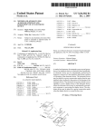
FIG. 1 is a perspective view showing a general construc
after it supplies the voltage to the power source terminal of
tion of an electronic endoscope system according to the
the semiconductor. On the other hand, when the control 50
present invention;
circuit is disconnected from the power source circuit by
FIG. 2 is a circuit diagram of the electronic endoscope
turning off the power source switch, the supply of voltage to
system;
the power source terminal is stopped after the output of the
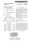
FIGS. 3(A) to 3(C) are sectional views sequentially
control signal to the signal terminal has been stopped.
In the case where the ?rst and second connectors are 55 showing various states of connectors and a power source
switch which are used in the above system, in the order of
connected to each other in the OFF~state of the power source
switch, and thereafter, the power source switch is turned on,
the control circuit exhibits a latch-up preventive function.
Therefore, a possible breakage of the CCD can be positively
prevented. Also, in the case where the power source switch
is turned off ?rst and then the connecting state between the
?rst and second connectors is removed, the control circuit
the connecting processes;
FIG. 4 is a sectional view showing connectors and a
power source switch according to a modi?ed embodiment;
60 and
FIG. 5 is a circuit diagram of a power source switch
according to a modi?ed embodiment.
exhibits the latch-up preventive function. Therefore, break
DETAILED DESCRIPTION OF THE
EMBODIMENTS
age of the CCD can be positively prevented.
However, in the case where the ?rst and second connec
tors are connected to each other after the power source
switch is turned on, the latch preventive function by the
65
One embodiment of a semiconductor control system
according to the present invention, which is mounted on an
5,554,893
3
4
electronic endoscope system, will be described with refer
which is connected to the control circuit 13 through a
plurality of electric wires 13a (a single wire as a group of
several wires is shown in FIG. 2), are mounted on the front
ence to FIGS. 1 to 3. As shown in FIGS. 1 and 2, the
electronic endoscope system comprises a control unit 10, a
monitor television M connected to the control unit 10, and
an endoscope 20 removably connected to the control unit 10.
As shown in FIG. 1, the endoscope 20 includes a body 21,
a ?exible insert portion 22 extending from a distal end of the
body 21, a tip 23 disposed on a distal end of the insert
wall 11a of the housing 11.
The receptacle 40 is known. As shown in FIG. 3A, the
receptacle 40 comprises a cylindrical body 41, a plurality of
pin-like male-type contact elements 42 supported within the
portion 22, a common cable 24 extending from a rear end of
the body 21, and two branch cables 24a and 24b branched
from the common cable 24. A distal end portion of the insert
portion 22 can be bent by means of remote control using a
control member (not shown) mounted on the body 21. A
plug 30 (?rst connector) is mounted on a distal end of the
branch cable 24a. An optical connector 25 is mounted also
15
on the distal end of the other branch cable 24b.
The tip 23 is provided at distal end face thereof with an
observation window and an illumination window. The .illu
mination window and the optical connector 25 are optically
connected to each other by a bundle of optical ?bers (not
shown). This bundle of optical ?bers are allowed to pass 20
through the insert portion 22, the body 21, the common cable
24, and the branch cable 24b. A light source device (not
shown) is received in the housing 11 of the control unit 10.
the optical connector 25 and the optical ?bers.
On the tip 23, there is provided a CCD 28 (semiconductor,
see FIG. 2) acting as an image pick-up element, which is
placed opposite to the observation window through an
objective lens system. A power source terminal 28a and
signal terminals 28b of this CCD 28, and a plurality of
female-type contact elements, as later described, of the plug
30 are connected together by a plurality of signal lines 29
(several signal lines are grouped and indicated by a single
periphery of the body 41. By ?xing this ?ange 41a to the
front wall 11a, the body 41 is ?xed to the front wall 11a. A
male-thread 41x is formed on the outer periphery of the
distal end of the body 41. The previously mentioned female
thread 35x of the connection ring 35 is threadedly engaged
with the male-thread 41x of this receptacle 40.
As shown in FIG. 2, the operating portion 16 of the power
source switch 14 is of a see-saw type and mounted on the
front wall 11a of the housing 11 but situated away from the
receptacle 40 as in the case with the conventional device. As
An illumination light from the light source device is irradi
ated through the illumination window after passing through
body 41. Each contact element 42 is allowed to extend in
parallel with the axis of the body 41 and surrounded by the
body 41, with its distal end facing the open end of the body
41. The body 41 is allowed to extend through the front wall
11a such that its axis extends perpendicular to the front wall
11a of the housing 11. A ?ange 41a is formed on the outer
25
shown in FIGS. 1 to 3, the operating portion 17 of the other
power source switch 15 protects from the front wall 11a in
the vicinity of the receptacle 40. In this embodiment,
although the operating portion 17 is arranged below the
receptacle 40, FIG. 2 does not show a correct positional
30
arrangement. It should be noted that this operating portion
17 may of course be situated above, right or left of the
receptacle 40.
As shown in FIG. 3A, the operating portion 17 of the
power source switch 15 includes a shaft 17a, a button
line in FIG. 2). These signal lines 29 are allowed to pass 35 portion 17b disposed at an external end of the shaft 17a, and
a spring retainer portion 17c disposed at an intermediate
portion of the shaft 17a. The shaft 17a is allowed to extend
through the front wall 11a, and a bracket 18 secured to the
front wall 11a. Between this bracket 18 and the spring
through the insert portion 22, the body 21, the common cable
24 and the branch cable 24a.
The above plug 30 is conventionally known and has, as
shown in FIG. 3A, a cylindrical body 31 and the plurality of
female~type contact elements 32 supported by the body 31.
40
The female contact elements 32 are received in a distal end ,
portion of the body 31 and allowed to extend in parallel to
the axis of the body 31, with its distal end facing an open end
of the body 31.
A connection ring 35 (pressing member) is mounted on
the plug 30 such that the ring can move in the axial direction
and turn about the plug 30. An engagement ?ange 35a is
45
engagement position where the engagement ?ange 35a
40. More speci?cally, as shown in FIG. 3A, the operator
holds the plug 30 such that the plug 30 coaxially faces the
55
receptacle 40. Then, by moving the plug 30 toward the
receptacle 40, the body 31 of the plug 30 is inserted into the
body 41 of the receptacle 40. Further movement of the plug
30 in the mentioned direction causes the contact elements 32
of the plug 30 to mutually ?t for electric connection to the
60 contact elements 42 of the receptacle 40 as shown in FIG.
ally arranged in a serial relation, are interposed between the
Operating portions 16 and 17 of the power source
switches 14 and 15 and a receptacle 40 (second connector),
is away from the front wall 11a and located forwardly of the
front wall 11a. Although an inner end of the shaft 17a is in
control unit 10 by inserting the plug 30 into the receptacle
contacts an engagement ?ange 31a formed on the outer
power source circuit 12 and the control circuit 13.
shaft 17 is biased outwardly by the resiliency of the coil
spring 19 and the spring retainer portion 170 is in contact
with the front wall 11a. In that state, the button portion 17b
switch 15 having the form of a micro-switch, the power
source switch 15 is in the OFF-state.
With the above construction, the CCD 28 of the endo
scope 20 is connected to the control circuit 13 within the
the connection ring 35. The movable range of the connection
ring 35 in the axial direction is determined by a front
source circuit 12 for converting an AC voltage to a DC
voltage, and a control circuit 13.
Two power source switches 14 and 15, which are mutu~
posed such that the spring 19 is wound on the shaft 17a. The
contact with a contact element 15a of the power source
formed on an intermediate portion of an inner periphery of
periphery of the body 31 and a rear engagement position
where an engagement ?ange 35a contacts an annular step
311] formed on the outer periphery of the body 31.
A female-thread 35x is formed in the inner periphery of
the connection ring 35 but at a location shifted forwardly
from the engagement ?ange 35a.
The control unit 10 includes, within a housing 11, a power
retainer portion 17c, a compressed coil spring 19 is inter
65
3B.
When the plug 30 is inserted, the distal end of the
female-thread 35x of the connection ring 35 contacts the
distal end of the male-thread 41x of the receptacle 40 and
therefore, the connection ring 35 is prevented from further
movement. As a result, the ring 35 is retreated relative to the
plug 30. The plug 30 is stopped by the step 31b being
5,554,893
5
6
contacted with the engagement ?ange 35a of the connection
ring 35. When the plug 30 is in its stop position, the contact
elements 32 of the plug 30 are all positively connected to all
contact elements 42 of the receptacle 40 over a predeter
mined length. It should be noted that the plug 30 may be
stopped by other suitable means. For example, it may be
designed such that before the step 31b contacts the ?ange
35a, the distal end of the body 31 of the plug 30 contacts a
stopper formed inside the receptacle 40.
In FIG. 3B, special attention should be paid to the fact that
when the distal end of the connection ring 35 is in contact
switch 15 is turned off, the connection ring 35 is removed
from the receptacle 40. Then, the plug 30 is pulled out of the
receptacle 40 to remove the connection between the contact
elements 32 and 42. At the time of the removal of connec
tion, since the controlling operation with respect to the CCD
28 is already ?nished, the removal of connection does not
affect adversely to the CCD 28.
The user is requested to turn o?“ the other power source
switch 14 before removing the connection between the plug
10
30 and the receptacle 40. Even if the user should forget this
turning-off operation, the latch-up prevention is ensured
15, the contact elements 32 of the plug 30 and the contact
elements 42 of the receptacle 40 are fully connected to each
other.
because the power source switch 15 is already in the
Off-position when the connection is to be removed.
In the above embodiment, the connection ring may be
connected to the receptacle by other suitable means than the
thread means. For example, it may be designed such that a
pin is formed on the outer periphery of the cylindrical
portion of the receptacle and an engagement groove is
formed in the connection ring. This engagement groove has
a ?rst portion extending in the axial direction from the distal
Next, as shown in FIG. 3C, the connection ring 35 is
turned so that the female~thread 35x is threadedly engaged
in a circumferential direction from a rear end of this ?rst
with the distal end of the receptacle 40, the connection ring
35 is away from the button portion 17b of the operating
portion 17 of the power source switch 15 and therefore, the
power source switch 15 is maintained in the OFF-state.
Accordingly, in this OFF-state of the power source switch
end of the connection ring, and a second portion extending
portion. The engagement groove is generally of an L~shape.
A mounting structure of the connection ring to the plug is the
same as’ the preceding embodiment. In this embodiment,
with the male-thread 41x of the receptacle 40. By doing this,
the plug 30 and the receptacle 40 are ?rmly connected
together (i.e., connection is completed).
When the connection ring 35 is brought into engagement
with the receptacle 40, the connection ring 35 is moved in
the axial direction and pushes the button portion 17b of the
25
?nished, the connection ring is moved in the axial direction
with the pin inserted in the ?rst portion of the engagement
groove, and then the connection ring is turned to bring the
pin to the second portion of the engagement groove to
connect the connection ring and the receptacle together, and
therefore to connect the receptacle and the plug together. In
the midway of the movement of the connection ring in the
axial direction with the pin positioned in the ?rst portion of
operating portion 17 of the power source switch 15 with its
distal end face. Therefore, the shaft 17a of the operating
portion 17 is retreated to push the contact element 15a of the
power source switch 15 with its inner end, so that the power
source switch 15 is turned on. This tuming-on operation of
the power source switch 15 is performed before the comple
tion of the threaded-engagement by the connection ring 35.
Next, the operating portion 16 of the power source switch
35
the engagement groove as mentioned above, the connection
ring pushes the operating portion of the power source switch
to turn on the power source switch.
14 is operated to turn on the power source switch 14. As a
FIG. 4 shows a modi?ed embodiment of a plug 30' and a
result, the DC voltage from the power source circuit 12 is
supplied to the control circuit 13. In response to this, the
control circuit 13 starts controlling the CCD 28. In the
control circuit 13, a constant voltage is supplied to the power
source terminal 28a of the CCD 28 ?rst and then, a control
receptacle 40'. In FIG. 4, like parts of the preceding embodi
ment are denoted by like reference numerals, respectively
and description thereof is omitted. In this embodiment, the
signal is output to the signal terminals 28b. What is impor
tant here is that at the time when the control circuit 13 starts
its controlling operation, connection between the connectors
30 and 40 are completed, and the control circuit 13 and the
CCD 38 are already electrically connected to each other. As
a result, the supply of constant voltage and the output of
control signal are performed in given order by the control
circuit 13 and therefore, latch-up can be positively prevented
and thus, breakage of the CCD 28 can be prevented.
Next, for removing the endoscope 20 from the control unit
10, the connection ring 35 is likewise turned but in the
after the electrical connection between the contact elements
of the plug and the contact elements of the receptacle is
45
plug 30' is simply inserted into the receptacle 40'. A pressing
?ange (pressing member) 39 is formed on the outer periph
ery of the body 31 of the plug 30'. During the process of
insertion of the plug 30' into the receptacle 40', the pressing
?ange 39 pushes the operating portion 17 of the power
source switch 15 to turn on the power source switch 15.
What is important here is that the forming position of the
pressing ?ange 39 on the body 31 is determined such that
50
after the electrical connection between all contact elements
32 of the plug 30' and all contact elements 42 of the
receptacle 40 is ?nished, the power source switch 15 is
turned on.
reverse way so as to be retreated. As this connection ring 35
As shown in FIG. 4, in the case where the connectors are
is retreated, the operating portion 17 is projected by the force
connected to each other simply by insertion, it may be
designed such that the diameter of the cylindrical portion of
55
of the coil spring 19 and the power source switch 15 is
turned off. By this, the control circuit 13 ?nishes its con
trolling operation with respect to the CCD 28. At the time of
the ?rst connector on the side of the CCD is made larger than
the diameter of the cylindrical portion of the second con’
?nish of the controlling operation, since the control circuit
nector on the side of the control unit, so that the contact
13 stops supplying the constant voltage to the power source 60 elements of them are electrically connected to each other
with the cylindrical portion of the second connector received
terminals 28a of the CCD 28 after the output of the control
in the cylindrical portion of the ?rst connector. In that case,
signal to the CCD 28 is stopped, latch-up of the CCD 28 can
the distal end face of the cylindrical portion of the ?rst
be prevented. At that time, since the connection between the
connector may be served as a pressing portion for pushing
plug 30 and the receptacle 40 is maintained, the latch-up
preventing operation is assuredly performed. By further 65 the operating portion of the power source switch.
In FIG. 5, a power source switch 15' comprises a relay
loosening the engagement of the connection ring 35 so as to
switch. The power source switch 15' is connected to a
further retreat the connection ring 35 after the power source
5,554,893
7
8
photo-coupler 50. This photo-coupler 50 comprises a pho
todiode 51 and a photo-transistor 52. The previously men
tioned shaft 17a of the operating portion 17 can be moved
in and out of between the photodiode 51 and the photo
transistor 52. Normally, since the shaft 17a is biased by the
coil spring, it is not located between the photodiode 51 and
the photo-transistor 52. In that case, the photo-transistor 52
is turned on upon receipt of light from the photodiode 51 and
a driving circuit 60 is opened so that the coil 15x is not
excited. When the shaft 17a is retreated pushed by the
connection ring 35 or the Pressing ?ange 39’ the Sha?_17a 10
between a ?rst position and a second position situ~
ated backwardly of said ?rst position and in a
direction generally perpendicular to said front wall
of said housing, said power source switch being in an
Off-state when said operating portion is in said ?rst
position, said power source switch being turned on in
a midway of the movement of said operating portion
from said ?rst position to said second position, said
?rst connector being provided with a pressing mem
ber, said pressing member, when said ?rst connector
enters between ihe photodlode 51 2.md [he Photo-Hammer
is connected to said second connector, being moved
toward said front wall of said housing, at that time,
5231.“ a {esuit’ smFe the phmo‘tr'tnslsmr 5.21s turned off’ the
said pressing member pushing said operating portion
dnvrng circuit 60 rs closed to excite the coil 15x. As a result,
the power source switch 15. is turned on.
_
15
It 18 acceptable thanh? mlcrmsyvltch 15 of FIG‘ 3 15 use?
as the pqwer source Switch a.nd its 69mm element 15” 1S
served directly as the operating portion. In that case, the
so that Said operating portion is moved from Said ?rst
position to Said second position; and
(e) said control unit including a second power source
switch disposed between said power source circuit and
Sal-d control unit and in a Sari a1 relation with the
power source swrtch 15 is mounted on the front surface of
the front wall 11a, and the contact element 15a rs pushed by 20
the pressing member directly mounted on the second con
?rst_mentioncd power Source Switch, a second Operzw
ing p cm on for turning on/off Said Second power Source
switch being provided on said front wall of said hous
ing but away from said second connector.
nector.
It is also acceptable that a pin is disposed, as the pressing
member, on the connector of the endoscope, and this pin is
allowed to extend through a through~hole formed in the front 25
wall, so that the pin pushes a contact element of a power
source switch disposed within the control unit.
In the above embodiments, the power source switch 14,
which can be turned on/olf by means of operation of the user,
may be omitted.
30
The present invention may be applied to a control system
2. A semiconductor control system comprising:
(a) an instrument including a senriconductor;
(b) a cable extending from said instrument;
(c) a ?rst connector mounted on one end of said cable and
electrically connected to said semiconductor, said ?rst
connector having a cylindrical ?rst body and a plurality
of ?rst contact_ elements
disposed within said ?rst body;
_
_
(d) _a comm], “mt mcludmg:
equipped with an image pick-up instrument having a CCD
(Q a housmg;
mounted on a distal end of a hard tuba7 instead of an
(11) asecond connector disposed on afront wall of said
endoscope. Also, the present invention may be applied to a
system for controlling semiconductors other than CCD.
35
,
.
housmg’ Sal‘? ?rst connector being {emovably con“
named to §md sew.“ 9°nmct°n Sald Second 6011'
what is Claimed is:
nector havrng a cylindrical second body and aplu
L A Semiconductor control System comprising:
ral-rty of second contact elements disposed within
.
.
.
.
said second body;
(a) an instrument mcludmg a semiconductor;
(b) a cable exlcnding from Said instrument;
(iii) a power source circuit received in said housing;
40
(c) a ?rst connector mounted on one end of said cable and
electrically connected to said semiconductor; and
(d) a Control unit including;
(1) a housing;
(iv) a control circuit received in said housing and
connected to said second connector;
(v) a power source switch through which said control
circuit is further connected to said power source
circuit, an operating portion for said power source
(ii) a second connector disposed on a front wall of said 45
Switch being mounted on said from Wall of Said
housing’ Said ?rst connector being removably Connected to Said Second Connector;
(iii) a power source circuit received in said housing;
housing in the vicinity of said second connector, said
operating portion being maintained in a ?rst position
Projected from Said from Wall of Said housing under
(iv) a control circuit received in said housing and
connected to said second connector; said control 50
circuit being further connected to said power source
circuit through a power source switch, said control
[be eifecl of a Spring disposed on a back Side of Said
from Wall of Said housing’ said Operating Pomon
being movable backwardly to a second Position, said
Power Source Switch being in an off-Slate when Said
circuit being capable of supplying aconstant voltage
Operating Po?ion is in Said ?rst Position, and Said
to a power source terminal of said semiconductor
POWer Source Switch being turned on in a midway of
when electrically connected to said power source 55
circuit by turning on said power Source Switch, and
terminal of said semiconductor, said control circuit
the backward movement of Said Operating Portion
from said ?rst position to said second position; and
(e) a connection ring mounted on an outer periphery of
said ?rst body of said ?rst connector, said connection
being capable of stopping the output of control signal
ring being tumable about said ?rst body and movable
to said control terminal and then stopping the supply 60
of voltage to said power source terminal when dis~
connected from said power source circuit by turning
off said power source;
(v) characterized in that said housing is provided on a
front wall thereof in the vicinity of said second 65
connector with an operating portion for said power
in an axial direction of said ?rst body within a prede
terrnined range, said connection ring being threadedly
engaged with said second body of said second connec
connected to each other, said connection ring pressing
said operating portion for said power source switch in
the course of the engagement of said connection ring
source switch, said operating portion being movable
with said second body, thereby said operating portion
thereafter supplying a control signal to a control
tor after said ?rst and second contact elements being
5,554,893
9
10
switch being mounted on said front wall of said
being moved backwardly to turn on said power source
switch.
housing in the vicinity of said second connector, said
operating portion being maintained in a ?rst position
projected from said front wall of said housing under
3. A semiconductor control system comprising:
(a) an instrument including a semiconductor;
(b) a cable extending from said instrument;
the e?’ect of a spring disposed on a back side of said
front wall of said housing, said operating portion
being movable backwardly to a second position, said
(0) a ?rst connector mounted on one end of said cable and
electrically connected to said semiconductor, said ?rst
connector having a cylindrical ?rst body and a plurality
of ?rst contact elements disposed within said ?rst body;
((1) a control unit including:
(i) a housing;
power source switch being in an off-state when said
10
power source switch being turned on in a midway of
the backward movement of said operating portion
from said ?rst position to said second position; and
7
(ii) a second connector disposed on a front wall of said
housing, said ?rst connector being removably con
nected to said second connector, said second con
operating portion is in said ?rst position, and said
15
(e) a ?ange formed on an outer periphery of said ?rst body
of said ?rst connector, said ?rst and second contact
nector having a cylindrical second body and a plu
rality of second contact elements disposed within
elements being connected to each other by moving said
said second body;
?ange being moved together with said ?rst connector to
press and backwardly move said operating portion for
(iii) a control circuit received in said housing;
(iv) a control circuit received in said housing and
connected to said second connector;
(v) a power source switch through which said control
circuit is further connected to said power source
circuit, an operating portion for said power source
?rst connector toward said second connector, said
said power source switch, said power source switch
being turned on after said ?rst and second contact
elements are connected.