1
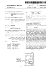
United States Patent [191
[l 1]
4,249,089
Wolford et 111.
[45]
Feb. 3, 1981
[54]
[75]
SHORT-TERM POWER DROPOUT
ARRANGEMENT USEFUL IN A
TELEVISION RECEIVER
OTHER PUBLICATIONS
"COP Microcontroller Family Chip User Manual”,
National Semiconductor, FIG. 2.4, p. 12, Sep. 1978.
Inventors: James J. Wolford; John B. George,
both of Indianapolis, 1nd.
[7 3] Assignee: RCA Corporation, New York, N.Y.
[7-1] Appl. No: 52,660
Primary Examiner-L. T. I-Iix
Assistant Examiner-James L. Dwyer
Attorney, Agent, or Firm-Eugene M. Whitacre; Paul J.
Rasmussen; Peter M. Emanuel
[57]
ABSTRACT
The control portion of a television receiver includes a
?ip ?op which when supplied with operating power
[22]
Filed:
Jun. 27, 1979
stores a binary signal having either an “on" level corre
sponding to the on condition of the receiver or an “ofF’
Int. Cl.3 ........................................... .. HOIH 83/00
[51]
[52] US. Cl.
[53]
[56]
307/140; 307/200 B;
307/142; 365/228
Field of Search ................. .. 307/66, 64, 125, 126,
307/140, 200 A, 200 B, 142, 141,296 R;
365/228, 229; 358/190; 325/492
References Cited
U.S. PATENT DOCUMENTS
3,558,912 l/l97l
3,575,612 4/1971
3,786,282 l/l974
4,052,701 10/1977
4,056,808 11/1977
4,099,372 7/1978
level corresponding to the off condition of the receiver.
In addition to a user responsive input arrangement for
selectively controlling the level of the binary signal, a
switching circuit is coupled to the ?ip ?op to return the
binary signal to its prior level after power line dropouts
having less than a predetermined duration, and other
wise causing the binary signal to have its “011" level.
The switching circuit is rendered operative at the end of
power line dropouts to cause the binary signal to have
its “on" level if an enabling signal selectively developed
Spall ............................ r. 307/200A
by a circuit including a capacitor and a diode connected
307/238
between the Hip Hop and capacitor during the presence
of operating power is still stored in the capacitor.
5 Claims, 1 Drawing Figure
STANDBY
POWER
1
4,249,089
2
the binary signal to its ?rst level if the enabling signal is
still present and to otherwise set the binary signal to its
SHORT-TERM POWER DROPOUT
second level.
ARRANGEMENT USEFUL IN A TELEVISION
RECEIVER
BRIEF DESCRIPTION OF THE DRAWING
The sole FIGURE shows partially in block diagram
BACKGROUND OF THE INVENTION
The present invention pertains to the ?eld of arrange
form and partially in schematic diagram form an ar
rangement constructed in accordance with the present
ments for maintaining the operational status of an elec
invention for maintaining information pertaining to
operational conditions of systems employed in a televi
sion receiver.
DETAILED DESCRIPTION OF THE DRAWING
trical system during short-term power dropouts.
Systems which derive their operating voltages from
the AC power line are susceptible to temporary inter
ruptions of their operation due to short-term power line
dropouts which occur, for example, when lightning
strikes near a power line.
Power line dropouts tend to annoy a user even if shot
In the sole FIGURE, a television receiver includes an
antenna 1, a tunner 3, an IF signal processing unit 5, a
term, since information related to particular operating
picture processing unit 7, a de?ection unit 9, a picture
tube 11, a sound signal processing unit 13, and a speaker
conditions of the system may be lost during the power
line dropout necessitating that the user reset the system
to the prior operating conditions after power returns.
This is particularly the case with systems employing
digital electrical control arrangements rather than me
chanical ones since the latter arrangements have inher
ent memory capabilities.
Not only are dropouts annoying, but when line
15 arranged in a conventional fashion. Tuner 3 includes
frequency tuning elements, e.g., tuned circuits including
varactor diodes (not shown) responsive to a tuning
voltage generated by a tuning voltage generator 17 to
tune the receiver to various channels in the television
frequency range. The components of the receiver so far
described are enclosed within a signal processing por
tion 19 and receive operating voltages, indicated sym
bolically by a single line 21, from a main power supply
power returns, the system may be set to undesirable
operating conditions. For example, in a television re
ceiver in which information related to whether the
(P.S.) unit 23.
receiver is off or on is stored in a memory cell, when
A user responsive control unit 25 generates control
power returns after a dropout, the memory cell may be
signals for selecting the on and off states of the receiver,
30
set to a state corresponding to the on condition of the
the volume level of the receiver and the channel to
receiver even though the receiver was intentionally
turned off before the dropout occurred. While arrange
ments are known for resetting digital control arrange
which the receiver is tuned. Control unit 25 generates
the various control signals in response to the depression
of ON/OFF, V. UP (Volume UP), V. DN (Volume
ments to a predetermined state when power returns, the
DowN), C. UP (Channel UP) and C. DN (Channel
predetermined state may not necessarily correspond to
the condition of the system before the power line drop
DowN) keys of a keyboard 27 mounted on the receiver.
Each key of keyboard 27 includes a normally opened
switch which is closed when the key is depressed by a
having to return the system to its previous condition.
user and returns to its normally opened position when
A variety of standby power supply arrangements are
known for maintaining the operation of a system or 40 the key is released.
when a key of keyboard 27 is depressed, a low logic
information related to operating conditions of a system
out occurred. As a result, the user may be annoyed by
during power line dropouts. Typically, these employ a
level signal, i.e., a signal at ground potential, is coupled
power storage element such as a battery or a capacitor.
to a decoder 29 included with control unit 25. In re
sponse, decoder 29 generates a respective one of an
Batteries are undesirable since they require replacement
by the user or recharging circuitry. While relatively
small value capacitors may be employed as power stor
age elements in systems which have digital control
apparatus requiring relatively small amounts of operat
ing power, relatively large value capacitors are needed
for storage elements in systems which have digital con
trol apparatus requiring relatively large amounts of
operating power. Since the storage capacity of a capaci
tor is related to its size, the use of a capacitor as a power
storage element can be undesirable. Moreover, both
batteries and relatively large value capacitors tend to be
expensive.
45
ON/OFF IN, V. UP, V. DN, C. UP or C. DN control
signal. The ON/OFF IN, V. UP, V. DN, C. UP and C.
DN signals are also generated in response to the opera
tion of ON/OFF, V. UP, V. DN, C. UP and C. DN
keys located on a battery powered remote control trans
mitter 31. In response to the operation of the keys of
transmitter 31, encoded carrier signals which, for exam
ple, are generated by remote control transmitter 31 and
coupled to decoder 29 through a remote control re
ceiver input unit 33, including a transducer, ampli?er
and demodulator (not shown) arranged in conventional
fashion. Decoder 29 decodes the demodulated output
signal of receiver input unit 33 to generate the ON/
OFF IN, V. UP, V. DN, C. UP and C. DN signals.
In a system including memory means for storing a
The ON/OFF IN signal is applied on an ON/OFF
60
binary signal having ?rst and second levels correspond
toggle FF (Flip Flop) 35 included within control unit
SUMMARY OF THE INVENTION
ing to ?rst (e. g., "on“) and second (e.g., “ofl") operating
conditions of the system during the presence of operat
ing power, storage means are coupled to the memory
25. ON/OFF FF 35 is alternately set and reset in re
sponse to the generation of successive ON/OFF IN
signals. The output signal of ON/OFF FF 35, hereinaf
means for selectively developing an enabling signal in
ter referred to as the ON/OFF OUT signal, is coupled
65
response to the first level and storing the enabling signal
to a relay driver including an NPN transistor 37 ar
for a pre-determined time after the start of power drop
ranged in a common emitter configuration to selectively
outs. Switching means coupled to the memory means is
apply current to a relay coil 39 coupled to its collector.
rendered operative at the end of power dropouts to set
3
4,249,089
A diode 41 shunts coil 39 to suppress the development
of transients.
When the ON/OFF OUT signal has a high logic
level, transistor 37 is conductive and relay coil 39 is
energized. When the ON/OFF OUT signal has a low
logic level, transistor 37 is nonconductive and relay coil
39 is unenergized. When coil 39 is energized, relay
contacts 43 are closed. As a result, AC line voltage is
applied to main power supply 23, causing operating
voltages to be applied to signal processing portion 19 to
turn the receiver on. When coil 39 is unenergized, the
receiver is turned off.
The V. UP and V. DN signals are applied to a volume
4
causes the ON/OFF OUT signal of ON/OFF FF 35 to
be set to the low logic level so that the receiver is off.
The POR 1 pulse also causes decoder 29, volume regis
ter 45 and D/A converter 47 to be set to predetermined
states such that when the receiver is initially turned on,
the volume level will be at approximately 50% of its
maximum value. When voltage V5 is initially devel
oped, a negative-going POR 2 signal is developed at the
junction of resistor 61 and capacitor 63 and applied to
the R input of channel number register 49. The POR 2
pulse causes the stages of channel number register 49 to
be set to predetermined states such that when the re
ceiver is initially turned on, the receiver will be tuned to
a
analog (D/A) converter 47 is responsive to the binary 5 predetermined channel such as, e.g., the lowest fre
quency channel.
signal contents of volume register 45 to generate an
register 45 included within control unit 25. A digital-to
The V1-V5 outputs of standby P.S. 51 have, in effect,
respective ?lter capacitors C1-C5 associated with them.
In the absence of AC line voltage, capacitors C1-C5
response to the V. UP signal thereby causing the vol
ume of the receiver to be increased. Similarly, the vol 20 will maintain voltages V1-V5 above levels necessary for
storing information in the load circuits to which they
ume of the receiver is decreased in response to a V. DN
signal.
are coupled for time periods determined by the current
requirements of the respective load circuits. Since chan
The C. UP and C. DN signals are coupled to a chan
nel number register 49 has a relatively low current
nel number register 49 outside of control unit 25. The
contents of channel number register 49 are increased 25 requirement, ?lter capacitor C5 need only have a rela
tively low capacitance value to maintain voltage V5
and decreased in response to the C. UP and C. DN
above a level necessary for storing binary signals in
signals, respectively. Tuning voltage generator 17 gen
erates the tuning voltage for tuner 3 in response to the
channel number register 49 representing the channel
ampli?er gain control signal for sound processing unit
13. The contents of volume register 45 are increased in
contents of channel number register 49. For this pur
number last selected for a time period greater than the
pose, tuning voltage generator 17 may include a phase 30 duration, e.g., 2 seconds, of most short-term power line
locked loop.
The AMI model number S2601 integrated circuit
commercially available from American Microsystems,
dropouts. However, since control unit 25 has relatively
high current requirements, ?lter capacitors C1 and C2
need have relatively high capacitance values to main
Inc., Santa Clara, California, is suitable for use as con
tain voltages V1 and V2 above levels necessary for
trol unit 25.
35 storing binary signals in ON/OFF FF 35 and in volume
Operating voltages for control unit 25, remote con
trol receiver input circuit 33, relay coil 39, and channel
register 45 representing the on/off and volume level
conditions of the receiver even during relatively short
term power line dropouts.
number register 49 are generated by a standby power
supply 51. Specifcially, P.S. 51 provides a positive oper
Capacitors having relatively large capacitance values
ating voltage V1 and a negative operating voltage V2 to 40 tend to be bulky and expensive and are therefore unde
control unit 25, a positive operating voltage V3 to re
sirable. Even so, conventionally large value ?lter capac
mote control receiver input circuit 33, a positive operat
itors have been employed to maintain information con~
ing voltage V4 to relay coil 39, and a positive operating
cerning operating conditions of a receiver during short
voltage V5 to channel number register 49.
term dropouts to avoid the inconvenience to a user of
Standby power supply 51 is continuously applied to 45 re-establishing the operating conditions of the receiver
the line. As a result, except during power line dropouts,
of the undesirability of having the receiver set to an
discussed below, control unit 25 is in condition to pro
cess commands initiated by a user by means of keyboard
27 mounted on the receiver or the keyboard of remote
control transmitter 31. In addition, even though the
receiver is off, i.e., relay contacts 43 are opened, operat
ing voltage for volume register 45 and channel number
register 49 is maintained. As a result, the volume level
and channel which were last selected are maintained
even while the receiver is off.
To initialize the operating conditions of the receiver
when line voltage is ?rst applied to the receiver, i.e.,
undesired condition after a short-term power line drop
out as discussed earlier.
In the present arrangement, circuitry is employed
having capacitors with relatively low capacitance val
ues for automatically setting ON/OFF FF 35 to the
state corresponding to the prior on or off condition of
the receiver after a short-term power dropout. In addi
tion, although the prior volume level is not maintained
during the power line dropout, the volume is set to a
level 50% of its maximum value in response to the gen
eration of a POR 1 pulse when voltage V1 is again
developed after the power line dropout. The 50% vol
signals are generated by power-up detectors 53 and 55
ume level is selected since it, at least statistically, ap
and applied to control unit 25 and channel number reg 60 proximates the volume level selected by a user prior to
ister 49, respectively, to reset these units to predeter
the power line dropout.
mined states. Power-up detector 53 includes a resistor
The short-term power line dropout circuitry for auto
61 and a capacitor 63 connected in series between the
matically setting ON/OFF FF 35 to its prior state after
V1 output of RS. 51 and signal ground. When voltage
a short-term power dropout includes an electronic
V1 is initially developed, a negative~going POR (Power
switch 65 including four NPN transistors 67, 69, 71, 73
On Reset) 1 pulse is developed at the junction of resistor
having their collector-emitter junctions connected in
57 and capacitor 59 and coupled to reset (R) inputs of
series between a conductor 87 at the on/off input of
various portions of control unit 25. The POR 1 pulse
decoder 29 and signal ground. Transistors 67,69, 71 and
when the receiver is “plugged in" to an AC outlet, reset
5
4,249,089
73 are con?gured so that switch 65 function as a logic
NAND gate.
One input of switch 65, at the base of transistor 71, is
connected to a capacitor 75 through a resistive voltage
divider 77. Capacitor 75 is selectively charged to a
positive voltage when a diode 79, connected between
the output of ON/OFF FF 35 and capacitor 75, is ren~
dered conductive. Diode 79 is conductive when the
ON/OFF OUT signal has the high logic level and is
nonconductive when the ON/OFF OUT signal has the
low logic level. Accordingly, capacitor 75 is charged
when the receiver is on and discharged when the re
ceiver is off. As long as capacitor 75 is charged to a
conduction threshold level (substantially equal to the
sum of its base-to-emitter voltage drop and the collec
tor-to-emitter voltage drop of transistor 73 when it is
conductive), NAND con?gured switch 65 is enabled to
connect the on/ol'f input decoder 29 at conductor 87 to
6
receiver to be turned on) except during a short enabling
time interval, e.g., lasting 2.8 seconds after the end of
the dropout. Speci?cally, when the dropout ends, volt
age V1 is applied to the base of transistor 67 through a
capacitor 89, which initially acts as a short circuit to
satisfy the law of charge conservation. As a result, tran
sistor 67 is enabled to be rendered conductive. Thereaf
ter, due to a charging path to negative voltage V2 pro
vided by a resistor 91, capacitor 89 begins to charge
toward negative voltage V2 and the voltage at the base
of transistor 67 begins to decrease. At the end of the
enabling time interval, when the voltage at the base of
transistor 67 falls below the turn-on threshold voltage
of transistor 67, transistor 67 and, as a result, switch 65
are disabled from being rendered conductive.
When a dropout occurs, voltages V1 and V2 rapidly
approach a common potential, i.e., that of signal
ground, because capacitors C1 and C2, respectively, are
discharged into their respective load circuits. This con
signal ground in response to the development of posi
20 dition causes capacitor 89 to rapidly discharge through
tive voltages at the other inputs of switch 65.
The value of capacitor 75 is desirably selected in
a conductive diode 93. Diode 93 is rendered conductive
conjunction with the impedance into which it dis
when a dropout occurs because capacitor 89 is charged
charges, i.e., the combined impedance of current di
in normal operation so as to forward bias diode 93 when
vider 77 and the impedance at the base of transistor 71,
voltages V1 and V2 are reduced in amplitude at the
so that it remains charged to a level higher than the 25
conduction threshold voltage of transistor 71 for 'a time
longer than the expected time duration, e.g., two sec
onds, of power line dropouts. Since the discharging
impedance for capacitor 75 can be made relatively high,
e.g., l megohms, the value of capacitor 75 can be rela
tively low, e.g., 4.7 microfarads.
Another input of switch 65 at the base of transistor 69
is connected to a pulse generating network 81 compris
ing a resistive voltage divider 83 and a capacitor 85.
When voltage V4 is generated after a short-term power 35
start of the dropout. Capacitor 89 is thereby discharged
and initiallized in preparation for the termination of the
power line dropout.
The POR 1 signal developed by power-up detector
53 is coupled to still another input of switch 65 at the
base of transistor 73 through a resistive voltage divider
95. Transistor 73 will only be enabled to be rendered
conductive when the POR 1 signal returns to a high
pulse generating network 81 and coupled to the base of
logic level after the termination of the negative-going
POR 1 pulse. Thus, switch 65 is disabled from being
rendered conductive until control unit 25 has been reset
in response to the negative-going POR 1 pulse. This
level just as if a user had depressed the ON/OFF key of
ing claims.
line dropout, a positive-going pulse is generated by
assures that the operation of switch 65 occurs when
transistor 69. ll' capacitor 75 is still charged to a level
control unit 25 is in a known condition.
above the conduction threshold voltage of transistor 71
and positive voltages have been developed at the base 40 While the present invention has been described with
reference to keys with normally opened input switches,
of transistors 67 and 73, as will be described below, the
it should be appreciated that the input switches may be
positive-going pulse applied to the base of transistor 69
normally closed. In this case, switch 65 should be con
will render switch 65 conductive. When switch 65 is
?gured to function as an AND gate rather than a
conductive, signal ground potential is applied to a con
NAND gate. of course, it is understood that these and
ductor 87 connected to the on/off input of decoder 29.
other modi?cations are contemplated to be within the
In response, decoder 29 causes the ON/OFF OUT
scope of the present invention as de?ned by the follow
signal of ON/OFF FF 35 to be set to the high logic
keyboard 27.
ll‘ capacitor 75 was not originally charged before the 50
power line dropout, because the receiver was off and
We claim:
1. In a system including power supply means for
normally developing operating voltages for said system,
the development of at least one of said operating volt
the ON/OFF OUT signal had the low logic level,
ages by said power supply means being subject to inter-.
switch 65 will not be enabled and the positive pulse
ruptions during power line dropouts, memory means
developed by pulse generator network 81 will have no
effect. Under these conditions, when the POR 1 pulse is 55 for storing a binary signal having ?rst and second levels
corresponding to on and off operating conditions, re
generated after the dropout ends, ON/OFF FF 35 will
spectively, of said system during the presence of said
be reset so that the receiver is off. The same occurs if
one of said operating voltages, control means for estab
the dropout lasts for a period longer than the dropout
lishing said on and off operating conditions of said sys
duration for which capacitor 75 is selected, e.g., two
seconds. Thus, as long as a dropout has a duration
shorter than the duration for which capacitor 75 is se
lected, the receiver will be returned to its prior on or off
condition. If a dropout has a duration longer than the
tem in response to said binary signal, and user respon
sive input means connected between a ?rst circuit point
and said memory means for selectively applying a pre
determined voltage developed at said ?rst point to said
memory means, said binary signal being alternately set
65 to said ?rst and second levels when said predetermined
will be turned off.
voltage is sequentially applied to said memory means by
A timing circuit 88, coupled to another input of
said input means, apparatus for returning said system
switch 65, at the base of transistor 67, inhibits switch 65
after said power line dropouts to the prior one of said
from being rendered conductive (thereby causing the
duration for which capacitor 75 is selected, the receiver
7
4,249,089
?rst and second operating conditions prevailing at the
onset of said power line dropouts, comprising:
storage means for selectively developing an enabling
signal in response to said ?rst level of said binary
signal during the presence of said one of said oper
8
after said binary signal is reset to said second level
after the ends of said power line dropouts.
2. The apparatus recited in claim 1 wherein:
said input means includes a manually operable switch
mechanism connected between said ?rst point and
said memory means for selectively applying ‘said
predetermined voltage to said memory means; and
said switching means is connected to a point between
said switch mechanism and said memory means.
3. The apparatus recited in claim 2 wherein:
ating voltages and for storing said enabling signal
for a ?rst predetermined time interval after the
beginnings of said power line dropouts; and
switch means including ?rst and second normally
non-conductive devices connected in series be
tween said ?rst point and a second point between
said switching means includes third and fourth nor
mally nonconductive devices connected in series
said input means and said memory means for selec
tively applying said predetermined voltage to said
- with said ?rst and said second devices between said
memory means when said ?rst and‘second devices
are both conductive, said ?rst device of said
switching means being conditioned to be conduc
being coupled to said resetting means to be ren
dered conductive after said binary signal is set to
tive in response to said enabling signal;
said switching means further including pulse generat
to said inhibiting means to be rendered conductive
?rst point and said second point, said third device
said second level, said fourth device being coupled
ing means coupled to said power supply means for
generating a pulse signal at the ends of said power
line dropouts, said second device of said switching
means being conditioned to be conductive in re
sponse to said pulse signal;
said switching means further including resetting 25
means coupled to said memory means for setting
said binary signal to said second level in response
to the development of a predetermined level of said
one of said operating voltages after the ends of said
power line dropouts;
30
said switching means further including inhibiting
during said predetermined time interval after the
ends of said power line dropouts.
4. The apparatus recited in claim 3 wherein:
said ?rst, second, third and fourth devices are bipolar
transistors having their collector-to-emitter junc
tions connected in series between said ?rst and said
second point and having their bases connected to
respective ones of said storage means, said pulse
generating means, said resetting means and said
inhibiting means.
5. The apparatus recited in claim 1 or 4 wherein:
said storage means includes a capacitor and a diode
connected between said capacitor and said memory
means, said diode being poled to conduct in re
sponse to said ?rst level of said binary signal.
means for inhibiting said ?rst and second devices of
said switching means from being conductive ex
cept during a second predetermined time interval
'
35
45
55
65
G
I
t
t