1
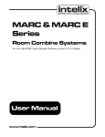
Psychologist Series Remote Monitor Systems User Manual Psychologist Mixer User Manual 2222 Pleasant View Road Middleton, Wisconsin 53562 (608) 831-0880 Fax (608) 831-1833 http:\\www.intelix.com [email protected] Model/ Serial Number Crosspoint ROM Application ROM Communication ROM PC Diskette Psychologist User Manual Revision H 0802 2002 Intelix. All rights reserved. 2 Psychologist Mixer User Manual Psychologist Mixer User Manual TABLE OF CONTENTS Introduction ................................................................................................................. 4 Safety Instruction ...................................................................................................................... 5 Maintainance Guidelines .......................................................................................................... 5 Quick Start ................................................................................................................... 6 System Description ............................................................................................................................. 10 Audio Matrix Mixer ............................................................................................................... 10 Front Panel .............................................................................................................................. 10 Rear Panel ............................................................................................................................... 10 Signal-to-Noise ....................................................................................................................... 12 System Balancing ................................................................................................................... 12 Inputs and Outputs .................................................................................................................. 14 DIP Switch Settings ................................................................................................................ 14 Mini-Mixer Remote Controllers .............................................................................. 15 8/1 Mini-Mixer ....................................................................................................................... 16 16/1 Mini-Mixer ..................................................................................................................... 16 16/2 Mini-Mixer ..................................................................................................................... 16 8/2 Mini-Mixer ....................................................................................................................... 16 32/1 Mini-Mixer ..................................................................................................................... 16 Mini-Mixer Configuration ...................................................................................................... 17 Status LED .............................................................................................................................. 17 Mini-Mixer location selector .................................................................................................. 18 Mini-Mixer Power .................................................................................................................. 18 ReO Bus Connections ............................................................................................................. 19 System Installation Reference .................................................................................. 20 AC Power Connection ............................................................................................................ 20 DC Power connection ............................................................................................................. 20 Audio Input and Output Connections ..................................................................................... 21 Grounding the Minimixer ....................................................................................................... 21 Audio Input Impedance .......................................................................................................... 22 Audio Output Impedance ........................................................................................................ 22 Recommended Input Connection Configurations .................................................................. 23 Mini-Mixer Connections ........................................................................................................ 24 Adding Mini-Mixers ............................................................................................................... 26 Troubleshooting Tips .............................................................................................................. 27 Appendix A Cable Pinouts........................................................................................ 28 PCD9F Mini-mixer Cable ...................................................................................................... 28 PRJ11/DB9 Mini-mixer Cable ............................................................................................... 28 Appendix B ................................................................................................................. 29 Technical Information ........................................................................................................................ 29 Warranty.............................................................................................................................................. 30 Psychologist Mixer User Manual 3 Psychologist Mixer User Manual Introduction This manual describes the components and operations of the Psychologist, a monitor mixing system based on the standard Intelix Matrix Mixer and Mini-Mixer remote controls. Together we’ll call them the Psychologist System, or just the system. This manual explains the features of the Psychologist System, its installation and operation. We strongly recommend that you use this manual when you install and operate the system. Each section of the manual describes an important aspect of the Psychologist System. This introductory section introduces the system, explaining important safety information and describing maintenance guidelines. The Quick Start section shows you how to install most common Psychologist configurations without having to read the rest of the manual (although we strongly suggest you read the entire manual before installing your system). The System Description section describes the hardware components of the system. These devices include the Matrix Mixer, the Mini-Mixer remote controllers, power supplies and cabling. The System Installation Reference section explains in detail how to install your Psychologist system, and how to add Mini-Mixers. You’ll need to use this section if your system is not a common configuration. Troubleshooting information is also provided. The Technical Information section provides system specifications. Enjoy your new Intelix Psychologist system! 2222 Pleasant View Road Middleton, Wisconsin 53562 (608) 831-0880 Fax (608) 831-1833 http:\\www.intelix.com [email protected] 4 Psychologist Mixer User Manual Psychologist Mixer User Manual Safety Instruction Note: Read all the directions carefully before use. Take all the precautions usually taken with electrical equipment. To protect both the users and the equipment: Grounding Make sure both the Matrix and the devices connected to it are properly grounded. Power Supply Use only the power supply provided by the manufacturer or one that meets the manufacturer’s specifications. Cords and Cables Route all cords and cables so that they will not be tripping hazards nor subject to damage (from being run over or pinched) that could cause them to become shock hazards. Pay particular attention to cords at plugs, convenience receptacles, and the point where they enter the Matrix and the MiniMixer remote controls. Fire If the Matrix or other electrical equipment catches fire, extinguish the fire using a carbon dioxide (CO2) extinguisher or any extinguisher rated for electrical fires. Do not use water or a water extinguisher. Maintainance Guidelines Electronic devices operate best in clean, well-ventilated environments. The Matrix unit has a greater than normal density of electronic components, and so generates more heat than the average electronic device. Place the Matrix where it will be well-ventilated, well away from other heat-generating equipment such as amplifiers. The Mini-Mixer remote controllers should also be kept clean. Route all cords and cables so that they will not be tripping hazards nor subject to damage from being run over or pinched. To minimize hum in the System, avoid placing the remotes and cables near EMF-producing devices such as electrical motors, fluorescent lights, AC power lines, SCR dimmers, etc. The remotes may be left connected and powered when not in use. Psychologist Mixer User Manual 5 Psychologist Mixer User Manual Quick Start This section describes how to get your Psychologist system up and running. This section covers most typical installations. If your system has any unusual features, or you need to know more about how your system works, read the chapter associated with each step. For more detailed installation instructions, see System Installation Reference, on page 20. 1. Connect the Intelix 18 Volt transformer to the AC power connector on the rear of the Mixer. Make sure that the flat side of the connector faces down. 2. Plug the 18 Volt transformer into a grounded 110 VAC outlet. 3. Connect audio inputs and outputs. Each input and output channel uses a triplet Phoenix connector. These connectors can be removed from the chassis for ease of wiring. The three wires within each signal line must be connected to the Phoenix connector as shown below. 6 Psychologist Mixer User Manual Psychologist Mixer User Manual Connect the inputs to the blocks on the left of the Matrix unit. Connect the outputs to the blocks on the right hand side of the Matrix unit. (This illustration shows an 8 x 8 Matrix Mixer. Your system may be different.) For more information on audio input and output connections, and information on impedance matching and connection configurations, see the Audio Input and Output Connections section on page 2123. 4. Connect the RCRJ12-18 cable to the ReO Bus connector on the rear panel of the Matrix Mixer. The following illustration shows the connections for the steps 4 through 6. Psychologist Mixer User Manual 7 Psychologist Mixer User Manual 5. Connect the RCRJ12-18 cable to the PRJ12/DB9F adapter. Because the Mini-Mixers use a 9-pin D connector cable, you’ll need to use the PRJ12/DB9F adapter to convert to the RJ12 connector used for the RCRJ12-18 cable that connects to the Matrix Mixer. 6. Connect the PRJ12/DB9F adapter to the PPS-12 power adapter. Intelix strongly recommends that the PPS-12 is installed as close to the Mini-Mixer remote locations as possible. If the Psychologist matrix is installed in a rack room away from the stage/studio location, it may be necessary to run a length of Cat 5 UTP cable to the stage/studio location for connection to the PRJ12/DB9F adapter. Intelix supplies an 18" cable, RCRJ12-18, for close proximity installations. Connect the PRJ12/DB9F adapter to the PPS-12 adapter. Plug the RCRJ12-18 cable into the PRJ12/ DB9F adapter and the ReO port on the rear of the matrix. 7. Connect a PC cable into the free end of the PPS-12 adapter. If your system requires local grounding, connect the black lead from the PPS-12 adaptor to a local ground; a building ground as shown or a local rack ground Plug the PPS-12 power supply into a grounded 110 VAC outlet. Typically the PPS-12 power supply goes into the series of PC cables at the beginning of the chain, as shown in the illustration below. For other options, or if your system has more than eight Mini-Mixers, see the MiniMixer Power section on page 18. Verify the settings of the Mini-Mixer location selectors (see page 18). 8 Psychologist Mixer User Manual Psychologist Mixer User Manual 8. Connect the Mini-Mixers one at a time. Connect the Mini-Mixer with lengths of PC cables. The DB9F connectors can connect to either of the two interchangeable ports on the side of the Mini-Mixers. Verify that the Mini-Mixer is powered up and communicating with the Matrix Mixer as indicated by a steady-on status LED before connecting the next Mini-Mixer. For more information on connecting Mini-Mixer, including directions on adding new MiniMixers to the system, see the Mini-Mixer Connections section on page 26. 9. Verify system operation. Turn on Audio sources and amplifiers. Listen to the output monitoring devices and adjust the mini-mixer volume controls. You are now ready for live,individual monitoring of the input sources. If your system does not seem to be working properly, see the Status LED section on page 17, and the Troubleshooting Tips section on page 27. Psychologist Mixer User Manual 9 Psychologist Mixer User Manual System Description This section describes the components of your Psychologist System. Read this section to familiarize yourself with the system components before you install your system. Audio Matrix Mixer The Psychologist is based on the Intelix Matrix Mixer, which allows audio signals from multiple sources to be sent to multiple destinations. The Matrix Mixer is designed so that audio inputs can be independently mixed to any and all outputs simultaneously. Front Panel A single LED on the front panel indicates that the Matrix is powered. Note: The LED is the only reliable indicator of the powered state of the Matrix. There is no power on/off switch on the Matrix. Rear Panel 9 10 18 VCT 4-pin power receptacle DC power receptacle For connection to a DC supply (+/- DC) or batteries. Reset button Restarts Matrix microprocessors. 10 Psychologist Mixer User Manual Psychologist Mixer User Manual LED/DIP Switch position: The “power” (red) LED lights when the Matrix is powered on. The “Status” (green) LED lights when the reset button is being pressed. The DIP switches are used to delete remote controls which are not responding. See Troubleshooting Tips on page 27 for more informa tion. DC Control Currently inactive DB25 female connector. Connect nothing to this connector. RS232 DB9 This DB9 nine pin female receptacle is used for computer and computer based monitoring and diagnostics. ReO Bus RJ12 (telephone type) connects to RPRJ12/DB9F adaptor. RS485 Currently unused 3 pin male connector. Do not use. 9 Inputs Strips of male screw terminal (Phoenix type) connectors. Each block accommodates four triplet plugs. 10 Outputs Strips of male screw terminal (Phoenix type) connectors. Each block accommodates four triplet plugs. Psychologist Mixer User Manual 11 Psychologist Mixer User Manual Signal-to-Noise The Psychologist Matrix is an attenuation only device, i.e. it cannot amplify signals passing through it. When all the level controls are fully on, there is unity gain, and when fully off, there is attenuation of –100dB. To obtain optimum audio performance of the Matrix, provide it with input signals of +4dB or greater. Depending on whether the input is balanced or unbalanced, the maximum input level should be no more than approximately +25dB. To maximize the signal-to-noise ratio, and to take full advantage of the performance of the Matrix, it is important to balance the system levels with most of the gain occurring before the signal enters the Matrix, rather than in the power amplifier afterwards. The Matrix has an absolute noise floor of approximately –80 dB. Proper level balancing, using the signal source capability of +26 dB, can result in signal-to-noise ratios of more than 100 dB. Using the power amp to raise signal levels, rather than a pre-Matrix amplifier or the Matrix itself, diminishes this high level of performance. For best performance, feed the Psychologist with direct outputs or subgroups from the main mixing console and raise levels to about +4dB. System Balancing To take full advantage of the Matrix’s high signal-to-noise performance follow the following steps: ♦ Drive the Matrix inputs with a signal of +4dBm to +26dBm. ♦ Set the Mini-Mixer volume controls to approximately the 2 o’clock position. ♦ Adjust the post Matrix system i.e. power amplifiers to produce the desired listening levels in the room or zone with this nominal setting of the Matrix. Fig. 12. Poor Signal Balancing. The drawing below shows the signal-to noise performance when the user attenuates a +4dB signal by 50 dB through the Matrix. This scenario commonly occurs when the user sets the Mini-Mixer controls at or below the nominal mid-point in an effort to have maximum adjustment range. However, since the control is attenuation only, the nominal midpoint is actually 50dB of attenuation. This setting results in the relatively poor signal-to noise ratio seen here. Audio Matrix Amplifier Source Mixer +40 dB Signal Curve SN = 40 dB 0 dB -20 dB SN = 65 dB -50 dB Noise Curve -90dB 12 Psychologist Mixer User Manual Psychologist Mixer User Manual Fig. 13. Correct Signal Balancing. This drawing shows the result of correctly following the system balancing procedure detailed above. The input signal is in the range of +4dB to +26 dB. With the Matrix attenuation controls set to -12dB the input signal is attenuated to -8dB. The resulting signalto-noise ratio is improved to more than 80dB. +20 dB or more input signal would give better than 100 dB signal-to-noise ration. Audio Source +40 dB +20dB 0 dB Matrix Mixer Amplifier Signal Curve Input range: +4dB-+26dB SN = 80 dB -20 dB SN = 90 dB -50 dB -90dB Noise Curve Psychologist Mixer User Manual 13 Psychologist Mixer User Manual Inputs and Outputs Each input and output channel uses a triplet Phoenix connector. For details on connecting inputs and outputs, see page 21-23. Inputs can be any line level source, such as musical instruments, microphones (preamplified to line level), tape players, CD players, etc. Input connections are made to the blocks on the left of the Matrix unit. The input plugs must be connected in ascending numerical order, from left to right, as printed on the Matrix. Outputs are wired to monitor amplifiers (headphone, floor wedge etc.) Output connections are made to the blocks on the right hand side of the Matrix unit. The output plugs must be connected in ascending numerical order, from left to right, as printed on the Matrix. Each output is associated with a single Mini-Mixer. For example, the Mini-Mixer at address 03 may control a pair of headphones connected to output number 3. The Mini-Mixer at address 10 may control a monitor speaker connected to output 10. Stereo (2 output) Mini-Mixers use two consecutive matrix outputs. (see Mini-Mixer location selector on page 18 for more information on stereo pairing). DIP Switch Settings The DIP switches are the set of eight small toggle switches next to the Reset LED on the rear panel. These switches define the mode of the central processor of the matrix system. They are set at the factory and generally should not be adjusted. (Normally all switches are down.) Baud Rate DIP switches 5 and 6 control the baud rate between the RS232 control port and an external controller. Note that this does not control the rate of communication between the matrix and the Psychologist remotes. Checksum DIP switch number 7 controls the activity of the checksum and escape byte function in RS232 communication. If the switch is in the up position, escape and checksum are used. If the switch is down escape byte and checksum are not used. Intelix recommends using escape byte and checksum in applications where RS232 communication may be hindered due to cable length (a maximum of 50 feet) or lack of shielding from external electronic noise. Escape byte and checksum should be turned off (switch 14 Psychologist Mixer User Manual Psychologist Mixer User Manual down) in installations which include a permanent RS232 controller such as AMX, Crestron or custom PC program. Note: After changing any DIP switches, you must resest the matrix by pressing the reset button on the rear panel. Changes will not take place unless you reset the matrix. Reset the Matrix Mixer memory. Resetting the Matrix Mixer memory will cause the Matrix Mixer to look for and re-establish communications with all of the Mini-Mixers. This solves most system problems. To reset the memory, locate the DIP switch on the rear panel of the Matrix Mixer and note the position of the switches. Set switches 1, 2 and 8 to up, all others down, as shown in the illustration below. This clears the memory. Then return the switches to their original positions. Unused switches Switches 1,2,3,4 and 8 are unused except as noted in “Reset the matrix mixer memory” above. Mini-Mixer Remote Controllers The Mini-Mixer remote controllers allow you to adjust the volume of each input channel independently of any other output channel. Each Mini-Mixer has independent controls for each input channel, plus a master volume control that affects all the channels. The status LED near the master volume control indicates that the unit is on. (See Status LED on page 17 for more information.) A typical Psychologist Mini-Mixer is shown below. Psychologist Mixer User Manual 15 Psychologist Mixer User Manual You can use several different styles of Mini-Mixers with the Psychologist system. Mini-Mixers have either rotary or slider potentiometer controls (“pots”), with 8, 16 or 32 input channels in monaural or stereo output. The different styles of Mini-Mixers, and the configurations that can result from their combined use, are described below. 8/1 Mini-Mixer 8/1 Mini-Mixer with rotary potentiometers The 8/1 Mini-Mixer is for use with up to eight monaural input channels. The 8 individual input channel potentiometers control each of the inputs independently. It controls the mix to one monaural output. 16/1 Mini-Mixer The 16/1 Mini-Mixer can provide up to 16 monaural matrix input channels. The 16 individual input channel potentiometers control each of the inputs independently to a single monaural output. 16/2 Mini-Mixer The 16/2 Mini-Mixer controls 16 input channels for stereo output (two output channels.) Each of the sixteen lower controls (pots or sliders) control the volume of a pair of adjacent outputs independently. The sixteen pots on the upper row are pan pots and control the left/right balance of each output pair independently. 8/2 Mini-Mixer 8/2 Mini-Mixer with slider potentiometers. The 8/2 Mini-Mixer controls eight input channels for stereo output (two output channels). The 8 input channel pots on the lower row control the overall volume of a pair of matrix adjacent outputs independently. The 8 pots on the upper row are the pan pots, and control the left/right balance of each of the output pair independently. 32/1 Mini-Mixer The 32/1 Mini Mixer provides up to 32 monaural input channels. The 32 individual input channel potentiometers control each of the inputs independently. Two rows of 16 volume controls adjust the mix of a single monaural output. 16 Psychologist Mixer User Manual Psychologist Mixer User Manual Mini-Mixer Configuration Status LED An LED near the master knob (see page 15) indicates the status of the Mini-Mixer. The output of the LED indicates the status of the Mini-Mixer. Steady On The Mini-Mixer is powered up and communicating with the Matrix. This is the normal condition. Flashing A flashing LED indicates an abnormal status. The rate of flashing indicates the problem. • Slow (50% duty cycle) - The Mini-Mixer is powered on but has lost communication with the Matrix. • Repeating single flash (every 2 seconds) - The Mini-Mixer is powered on but has not established communication with the Matrix. • Repeating double flash (every 2 seconds) - The Mini-Mixer has been commanded to go to set-up mode by the Matrix Mixer. This state is normally active for a short duration when new remotes are plugged into the system and then changes to the normal, steady on condition. • Fast flash (50% duty cycle) - The Mini-Mixer has conflicting output address assignments. Initial conflict may disappear as the system continues its initialization procedure. This could be caused by two Mini-Mixers having the same assignment, if stereo assignments overlap, or if assignments are outside the range of the Matrix Mixer (including 00). To correct, change output selectors of one of the two remotes with overlapping assignments. Steady Off The unit doesn’t have power. Check the power supply. However, if the LED never blinks following powering, there is either no power to the remote, or a fault in its electronics. For troubleshooting help, see Troubleshooting Tips on page 27. Psychologist Mixer User Manual 17 Psychologist Mixer User Manual Mini-Mixer location selector Each Psychologist system ships with Mini-Mixers configured to control an output on the Matrix. Follow the instructions below to add additional Mini-Mixers or alter the system configuration. The two rotary decimal switches (see page 26) within the Mini-Mixer determine which physical output location (and I/O channel) the Matrix Mixer associates with that Mini-Mixer. Monaural MiniMixers take one output location on the Matrix Mixer, and stereo Mini-Mixers require two adjacent output locations. You can view the assignment of each Mini-Mixer by looking at the small numbers inside the holes on the side of the unit near the cable connectors. Two small holes in the bottom of the Mini-Mixer unit allow you to change the assignment switch settings. For information on adding or reconfiguring Mini-Mixers with you system, see Adding Mini-Mixers on page 26. Mini-Mixer Power All remote controls are powered by an external power supply, either the supplied transformer, or another equivalent supply. The supplied Intelix PPS-12 contains a 2 amp transformer and supplies power to multiple remote controls in a typical system. Large systems may require more than one PPS-12. The PPS-12 supplies can be connected into the system in any order. If you use a long cable between the Matrix Mixer and the Mini-Mixers, locate the PPS-12 near the Mini-Mixers, not near the Matrix Mixer. If your system requires two power supplies, put one at each end of the Mini-Mixer chain. For systems with more than two power supplies, distribute the power supplies equally between the Mini-Mixers. If you use AC power, you cannot parallel them! Only DC power supplies can be paralleled. You can create a backup power supply by connecting an additional unit in parallel with the main power supply. The supply with the lower input voltage will act as a backup. Refer to the following listing for exact power specifications of any external power supply. 18 Remote Type Current Required Maximum number per PPS- 12 power supply 8/1 62 mA 32 8/2 112 mA 16 16/1 112 mA 16 16/2 162 mA 8 32/1 162 mA 8 Psychologist Mixer User Manual Psychologist Mixer User Manual Power is fed to all Mini-Mixers via two pins on each 9-pin D connector. See below for a wiring diagram. For DC power pin 6 is power ground and pin 9 is power plus (+). An external power supply that provides the power connection may be either AC or DC. If DC, positive voltage should be connected to pin 9, and ground connected to pin 6. The voltage should be 9 to 12 volts. Note: The color code shown below is specific for Gepco 6608, the cable recommended by Intelix. ReO Bus Connections The ReO bus that connects the minimixer remotes to the matrix mixer has the following pinout. Psychologist Mixer User Manual 19 Psychologist Mixer User Manual System Installation Reference This section presents installation instructions for all systems. In this section you’ll find installation details not found in the Quick Start section. AC Power Connection Intelix supplies an 18 Volt, 3.0 (or 1.5) Amp center-tapped transformer to power the Mixer. If you use another AC supply, it must supply 18 volts and have at least a 21 VA rating for an 8 x 8 matrix and 60 Volt-Amp rating for larger matrices. The following figure shows the the AC Power jack on the rear panel. DC Power connection The mixer can also be connected to a DC power supply via the Molex-style DC power jack on the rear panel. The DC supply can be used as the sole power source or as an on-line backup. Note: If the DC supply is used as backup, it must meet the following voltage requirements: √ A regulated supply (for example, a battery) must be between 17 and 18 volts (voltages greater than 18 will drain the DC supply; using less than 17 volts will reduce the dynamic range of the mixer). √ An unregulated DC supply must be between 17 and 18 volts. If the supply is less than 17 volts, a hum may be audible at the outputs. The current supplied mustbe at least 1.5 A for an 8 x 8 matrix and 3 A for larger matrices. The wire configuration and voltage requirements are as shown in the right-hand figure below. Rear Panel View 20 Psychologist Mixer User Manual Psychologist Mixer User Manual Audio Input and Output Connections Each input and output channel uses a triplet Phoenix connector. The three wires within each signal line must be connected to the Phoenix connector as shown below. For ease of wiring each connector can be removed from the chassis by pulling it straight out. Ground Minus (–) Plus (+) The Phoenix connectors can only be attached to the Matrix receptacles in one orientation. However, the Matrix receptacle is a strip rather than individual sites, so a plug can be connected to three pins which are not a set. Take extra care when connecting to blocks in which not all the pins will be used. The Matrix cannot control a signal line when the connections are not made correctly. Input connections are made to the blocks on the left of the Matrix unit. Inputs are any line-level source and must be connected in ascending numerical order, from left to right, as printed on the Matrix. Output connections are made to the blocks on the right hand side of the Matrix unit. Line level outputs are connected in ascending numerical order, from left to right, as printed on the Matrix. Grounding the Minimixer In high static environments, it may be necessary to add local grounds to Psychologist minimixers. This is most easily done at installation time, so if you suspect that you will have high static conditions such as thick carpet or other static causing conditions, you should locally ground your minimixers at the time of installation. Every minimixer in the system should be grounded in this way. Local grounding is accomplished by connecting pin 8 of the minimixer cable to the nearest local ground. Psychologist Mixer User Manual 21 Psychologist Mixer User Manual Audio Input Impedance Any line-level audio input can be mixed and routed using the Matrix. The audio input to the Matrix is can be either electronically balanced (impedance of 20KΩ), or it can be unbalanced (impedance of 10KΩ) by the user. The correct way to unbalance the input is to “float” by leaving the unused pin open, as shown below. Matrix Input Connector Matrix Input Connector Audio Output Impedance The audio output from the Matrix is electronically balanced (impedance of 440 Ω), but it can be unbalanced (impedance of 220 Ω) by the user. The correct way to unbalance the output is to tie one of the balanced legs to ground, as shown below. The Matrix is designed to give a 6 dB boost (which compensates for the signal-level loss due to unbalancing) to a signal unbalanced in this way. Therefore, this method of unbalancing is preferable to floating one side of the pair of leads to unbalance it. Matrix Output Connector Matrix Output Connector Each output is associated with a Mini-Mixer. For example, the 8/1 Mini-Mixer set to output location 03 may control a pair of headphones connected to output number 3. The 8/2 Mini-Mixer set to output location 10 may control a pair of monitor speakers connected to outputs 10 and 11. 22 Psychologist Mixer User Manual Psychologist Mixer User Manual Recommended Input Connection Configurations The audio input to the Matrix can be either electronically balanced (impedance of 20kΩ), or it can be unbalanced (impedance of 10kΩ) by the user. The connection configurations shown below are all possible. Choose the configuration that best fits your needs. Ground Minus (–) Plus (+) pin 1 pin 2 + - pin 3 + + pin 1 + pin 2 - pin 3 + + Type: isolated ground (unbalanced) Gain: unity Property: ground currents and induced noise rejected from signal Type: common ground (unbalanced) Gain: +6 dB Property: slight gain boost; possible ground noise in signal pin 1 pin 2 + pin 3 + + Type: common ground (unbalanced) Gain: unity Property: possible ground noise in signal pin 1 + pin 2 - pin 3 + + Psychologist Mixer User Manual 23 Psychologist Mixer User Manual Mini-Mixer Connections The Psychologist system uses a parallel wiring scheme to communicate bi-directionally with the Mini-Mixer remote controls. The Mini-Mixers connect to the PPS-12 power adapter and each other with Intelix PC cables, female to female 9 pin. Total cable length may not exceed 3000 ft. If using a daisy chain configuration, you will use both DB9 connectors on each remote except the last one in the chain. The ports are interchangeable so either port can serve as the input or output. If using a star configuration, you will only use one of the DB9 ports on each mixer. It does not matter which one. You can use both configurations together in the same system. Follow the steps below to connect the Mini-Mixers to rest of the Psychologist system. Refer to drawing on page 25. 1. Intelix strongly recommends that the PPS-12 is installed as close to the Mini-Mixer remote locations as possible. If the Psychologist matrix is installed in a rack room away from the stage/studio location, it may be necessary to run a length of Cat 5 UTP cable to the stage/studio location for connection to the PRJ12/DB9F adapter. Intelix supplies an 18" cable, RCRJ12-18, for close proximity installations. Connect the PRJ12/DB9F adapter to the PPS-12 adapter. Plug the RCRJ12-18 cable into the PRJ12/ DB9F adapter and the ReO port on the rear of the matrix. 2. Plug in the PPS-12 power supply. Note: Larger systems may require more than 1 PPS-12 power supply module. Refer to the chart on p.18 of this manual for more information. If 2 PPS-12 power supplies are required in a daisy chain configuration, they should be placed at opposite ends of the chain. If 3 PPS-12 supplies or more are required, they should be evenly spaced in the Mini-Mixer chain. Only DC power supplies can be connected in parallel! 3. Connect the first Mini-Mixer, which should be set at station/output 01 using the rotary switches, with the desired length of PC cable. Watch the LED, located near the Master level control. The LED will blink once every 2 seconds, for up to 30 seconds, and then it will turn on steady. When this occurs, the matrix has recognized the remote. You can then repeat this procedure for all of the remotes in your system in order of their station/output numbers. If you encounter any problems while performing this procedure, it is best to clear the matrix memory and start the procedure over. (See Reset the Matrix Memory on p.15) Otherwise station conflicts may occur. Once the Mini-Mixers have been recognized by the matrix, their station/output is stored in its internal memory. You can then move them to any physical location that you wish. However, they will always control the station/output for which they are assigned. Do not change the remote station/output settings once they are installed. The new settings will conflict with the settings already stored in the matrix memory. If you need to reconfigure the system it is better to clear the matrix memory and start the remote installation procedure over. 24 Psychologist Mixer User Manual Psychologist Mixer User Manual This drawing illustrates the steps in connecting Mini-Mixers to the Psychologist system. (see page 24). Psychologist Mixer User Manual 25 Psychologist Mixer User Manual Adding Mini-Mixers Follow the steps below to add Mini-Mixers or reconfigure your system. 1. Determine which audio output locations are to be controlled by each Mini-Mixer. Each Mini-Mixer must have a unique output location assignment on the Matrix Mixer. Mono MiniMixers use a single output location. For example, if you install a new 8/1 Mini-Mixer at output location 06, the next new Mini-Mixer would go at output location 07. Stereo Mini-Mixers use two consecutive outputs on the Matrix Mixer; the location it is set for and the next higher output location. For example, if you install a new 8/2 Mini-Mixer at output 06, it would control outputs 06 and 07. The next new Mini-Mixer would be set for output 08. 2. Set the rotary switch on the Mini-Mixer to the correct output assignment. Insert a small screwdriver into the holes in the bottom of the unit and turn the rotary switches to the correct matrix output assignment for that Mini-Mixer. The output assignment is a regular (1-based) decimal number, so 01 is output one and 16 is sixteen, and so on. The output range is from 01 to 99. 3. Install the new Mini-Mixer to the system. Connect the Mini-Mixer using the appropriate length of PC cable. Connect each Mini-Mixer one at a time. The Matrix will recognize the new Mini-Mixer within about a minute. Verify that the Mini-Mixer is powered up and communicating with the Matrix Mixer, as indicated by a steady-on status LED, before connecting the next Mini-Mixer. 26 Psychologist Mixer User Manual Psychologist Mixer User Manual Troubleshooting Tips If your Psychologist system doesn’t work the way you expect, chances are that one of the MiniMixers is configured incorrectly, or the Matrix Mixer can’t decide which output a Mini-Mixer belongs to. Symptoms you see may include: • No response from one or more Mini-Mixers • Blinking status LED on one or more Mini-Mixer • Very slow response to controls on Mini-Mixer The steps to take in all of these cases is the same. Follow these suggestions: 1. Wait a minute or so. It takes about 30 seconds for the Matrix Mixer to establish communications with the Mini-Mixers after you turn the system on. It takes about one minute for an new Mini-Mixers to be acknowledged by the Matrix Mixer. If the problem persists, continue with step 2. 2. Turn or slide the Mini-Mixer master volume control. This forces the Matrix Mixer to read the output assignment setting. 3. Verify that each Mini-Mixer has the correct output assignment. Each Mini-Mixer must have a unique output location assignment on the Matrix Mixer. Mono MiniMixer’s use a single output location. For example, if you install a new 8/1 Mini-Mixer at output location 06, the next new Mini-Mixer would go at output location 07. Stereo Mini-Mixer’s use two outputs on the Matrix Mixer; the location it is set for and the next higher output location. For example, if you install a new 8/2 Mini-Mixer at output 06, it would use outputs 06 and 07. The next new Mini-Mixer would go at output 08. Continue with step 4 (even if you found a mistake with the addressing). 4. Reset the Matrix Mixer memory. Resetting the Matrix Mixer memory will cause the Matrix Mixer to look for and re-establish communications with all of the Mini-Mixers. This solves most system problems. To reset the memory, locate the DIP switch on the rear panel of the Matrix Mixer and note the position of the switches. Set switches 1, 2 and 8 to up, all others down, as shown in the illustration below. This clears the memory. Then return the switches to their original positions. Psychologist Mixer User Manual 27 Psychologist Mixer User Manual Appendix A Cable Pinouts This appendix shows the pinout for the two most commonly made cables for the Psychologist Mixers. Both cables are provided from the factory; these pinouts are provided for those whose installations require the manufacture of special cables. The system drawing below shows where the cables occur in the system. The lower drawings show the pinouts of those cables. PC Mini-mixer Cable PRJ12/DB9F Mini-mixer Cable 2 8 Psychologist Mixer User Manual Psychologist Mixer User Manual Appendix B Technical Information Specifications Signal-to-Noise Input Impedance (electronically balanced) Nominal Input Level Maximum Input Level Output Impedance (electronically balanced) Nominal Output Level Maximum Output Level Frequency Response Crosstalk (adjacent channels ) Gain Control Range (attenuation only) Gain Control Resolution Power Requirements Matrix: 8x8 larger than 8x8 current draw Mini-Mixers: Voltage current draw Ref +26 dBV = 90dB 20KΩ + 4 dB nominal Maximum 24 dBm 440 Ω + 4 dB +26 dBm ±0.5 dB from 20 Hz to 20 kHz -80dB at 2Khz and at 20KHz 100 dB 0.4 dB 18 VAC center-tapped, 30 VA 18 VAC center-tapped, 60 VA ±18 - 24 VDC, 450 mA 21VA for 8X8; 60VA for larger +9-12 VAC or VDC 62-162 mA see page 18 for details Dimensions Matrix Mini-Mixer Remote (8x1and 8x2 versions) (16/1,16/2 and32/1 versions) Shipping Weight Matrix Mini-Mixers Psychologist Mixer User Manual 19" x 14" x 3.5" (48.2 cm x 35.6 cm x 8.9 cm) 7.75" x 4.5" x 2.5" (19.5 cm x 11.4 cm x 6.5 cm) 13.25” x 4.5” x 2.5” (33.7 cm x 11.4 cm x 6.5cm)p 20.3 lb. (9.20 kg) .78lb min-2.2lb max 29 Psychologist Mixer User Manual Warranty All Intelix products are guaranteed against malfunction due to defects in materials or workmanship for two years after date of purchase. If such malfunction occurs during the specified period, this product will be repaired or replaced, at our option, without charge. Further, the “Fresh Start” program (available to U.S. customers only) ensures that a product which has been repaired/replaced is itself guaranteed for six months. This six-month guarantee applies even if the warranty repair/replacement occurs within less than six months of the end of the original two-year warranty period. Dealer is responsible for the cost and other shipping and insurance associated with shipping goods to Intelix. Intelix will match shipping method and pay associated costs to return goods to dealer location. This warranty does not cover 1) malfunction resulting from use of the product other than as specified in the user manual; 2) malfunction resulting from abuse or misuse of the product; 3) exterior chassis appearance; 4) malfunction occurring after repairs have been made by anyone other than Intelix or any of its authorized dealers; 5) acts of nature; 6) optional embedded software upgrades or updates. Only qualified service personnel should provide all repair and service of Intelix products and other attempts at service or repair may void the warranty. Contact Intelix for a list of authorized service agents. Warranty service is only offered after a return authorization number has been generated by an authorized Intelix representative. Goods being returned for warranty service must be sent in original packaging. Intelix will not accept liability for those goods shipped in packaging other than the original factory container. All repair and other service of Matrix Mixers and Remotes should be provided only by qualified service personnel.Contact Intelix for a list of authorized service agents. Other attempts at service or repair may void the warranty. 2222 Pleasant View Road Middleton, WI 53562 (608) 831-0880 fax: (608) 831-1833 e-mail: [email protected] www.intelix.com 3 0 Psychologist Mixer User Manual