1
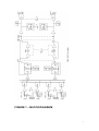
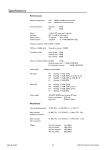
T L Audio
User Manual
Ebony Series A4 Summer
TL Audio Limited, Letchworth, England.
Tel 01462 492090, Fax 01462 492097.
www.tlaudio.co.uk
email: [email protected]
CONTENTS.
CONTENTS. ...................................................................................................................................................2
INTRODUCTION..........................................................................................................................................3
WHY CLASS-A? ............................................................................................................................................4
WHY TUBES? ................................................................................................................................................4
WHY BALANCED I/O? ..................................................................................................................................4
PRECAUTIONS.............................................................................................................................................6
BLOCK DIAGRAM ......................................................................................................................................7
INSTALLATION ...........................................................................................................................................8
AC Mains Supply......................................................................................................................................8
Inputs. .......................................................................................................................................................8
Insertion Points. .......................................................................................................................................9
Balanced XLR Outputs. .........................................................................................................................10
Level Selection. ......................................................................................................................................10
Ventilation. .............................................................................................................................................10
OPERATION................................................................................................................................................11
Input Gain stage.....................................................................................................................................11
Channel Pan Control.............................................................................................................................11
Input switching .......................................................................................................................................11
Tube Stage Drive and Peak LEDs. .......................................................................................................11
Tube Drive Control................................................................................................................................11
Insertion Points ......................................................................................................................................12
Output Gain............................................................................................................................................12
Metering .................................................................................................................................................12
SPECIFICATIONS......................................................................................................................................13
Power Requirements:.............................................................................................................................14
SERVICE.......................................................................................................................................................15
2
INTRODUCTION
Thank you for purchasing the Ebony A4 Summer. The TL Audio Ebony Series of
audio processors are a sleek looking range of discrete Class A processors designed to
heighten your audio experience; they use signal paths constructed from discrete
transistor “Class A” circuits, with switchable variable drive tube stages, putting you in
control of how ‘creamy’ or how ‘cool’ your unit sounds. These techniques provide
very high quality, uncoloured audio, with the option to add valve warmth at the touch
of a button.
Hand assembled in England to the highest standards, the Ebony uses stylish, quality
chrome knobs together with a high gloss black finish to make the exterior look just as
smooth as the circuits sound. The Ebony Series have all the features you come to
expect with TL Audio, including balanced I/O, multi input options, analogue VU
metering and intuitive, precise controls. A combination of supreme quality, unrivalled
sound and stylish aesthetics - this range offers superior analogue processing to
accompany a digital world.
The Ebony Series A4 Summer is a 16 channel unit, accepting balanced or unbalanced
line inputs, switchable between +4 and -10dB, via TRS Jack or DSUB connector.
Each channel has individual Pan control, and there is also master gain control and
balanced insert points with bypass. A tube stage may be switched into the master
signal path, with variable drive control.
The block diagram of the processor is shown in fig.1. A discrete Class A electronically
balanced input is used, delivering superior audio performance with very low noise,
and wide bandwidth
The tube stage has a variable drive control, with the signal level indicated by the
variable intensity “Drive” LED and “Peak” LED. Use of this feature typically
introduces 1% to 10% harmonic distortion, predominately second harmonic, without
changing the output level from the unit. This even harmonic distortion gives the colour
and sound that tubes are famed for. The tube stage can be selected or bypassed as
required.
A VU meter is provided, which can be selected to either input or output signals. The
meter is also provided with a “+10dB” switch, which keeps the reading on the scale
when driving a high level out (to a DAW, for example). In the +10 mode, 0VU is
calibrated as +14dBu out.
3
Why Class-A?
Class A circuits are designed with a constant current flowing through all of the
transistors, which is sufficient to drive the peak output required from each block of the
circuit. This ensures that every transistor is kept at its optimum operating point,
minimising non-linearities due to changes in current and internal thermal effects, and
eliminating the objectionable “cross-over” distortion typical of class AB circuits.
Due to the higher steady state (or “quiescent”) currents used, the power dissipation of
class A circuits is substantially higher than can in general be handled by integrated
circuits. It is also possible to design discrete transistor circuits to operate at higher
voltage rails than are available for audio integrated circuits, adding the benefit of
greater headroom and improved dynamic range. For these reasons, there are no
integrated circuits in the audio paths of the Ebony Series so that they enjoy this
improved dynamic range and greater headroom.
The outstanding audio quality is reflected in the technical specification of the units,
with particularly low noise and distortion, and wide frequency response.
Why Tubes?
Valves - or “Tubes” - have long been associated with excellent audio quality,
recognised as adding “warmth” or “depth” to a signal. Driving the valves harder
results in an increasing level of mainly second harmonic distortion, which is
responsible for the characteristic overdriven valve sound.
The Ebony Series feature variable drive valve circuits, which may be switched into the
audio paths, or bypassed completely. The valve drive control varies the signal level
through the valve stage, without affecting the overall gain from input to output. It is
therefore possible to vary to the degree of harmonics added by the valve, from subtle
warming to crunchy overdrive, with a single control. The signal level through the
valve is displayed by the variable intensity “Drive” LED and the “Peak” LED.
Why Balanced I/O?
Balanced I/O (Inputs and Outputs) are always preferable to unbalanced connection in
an audio system. A balanced signal consists of signal phase and non-phase
connections, which form a differential pair, independent of the ground (or earth)
connection. Noise, particularly mains hum and high frequency interference can often
be present in unbalanced systems due to small differences in ground potential or
circulating ground currents (“loops”) between units, where the signal phase (only) is
taken as an absolute value with respect to ground.
4
A correctly designed balanced interface should have both phase and non-phase signals
of equal magnitude (and source impedance), but should allow either of the phase and
non-phase signals to be connected to an arbitrary electrical point (e.g. ground) without
changing the differential level. Therefore, if, for instance, the non-phase signal is
shorted to ground by an unbalanced input on a piece of equipment, then the phase
signal should double in magnitude to compensate. Such an arrangement is referred to
as “floating” or “ground-free”. Balanced signals require 3 pin connectors, such as
XLR’s or TRS jack plugs, carrying the phase and non-phase signals, plus a screening
ground connection.
Naturally, the Ebony Series features balanced, ground-free signals for all line inputs
and outputs, as well as insertion points where present. The range is also compatible
with unbalanced equipment, as described above.
Please read this manual fully before installing or operating the Processor.
5
PRECAUTIONS
The TL Audio Ebony Summer requires very little installation, but like all electrical
equipment, care must be taken to ensure reliable, safe operation. The following points
should always be observed:
- All mains wiring should be installed and checked by a qualified
electrician,
- Ensure the mains operating voltage stated on the rear panel is correct
before connecting to the mains supply,
- Never operate the unit with any cover removed,
- Do not expose to rain or moisture, as this may present an electric
shock hazard,
- Replace the fuse with the correct type and rating only.
Warning: This equipment must be earthed.
6
FIGURE 1 – BLOCK DIAGRAM
7
INSTALLATION
AC Mains Supply.
The unit is fitted with an internationally approved 3 pin IEC connector. A mating
socket with power cord and mains plug is supplied. All mains wiring should be
performed by a qualified electrician with all power switched off, and the earth
connection must be used.
Please note that when using this unit with alternate supply voltages (in foreign
countries, for example) the internal wiring of the unit may be set for 115V (accepting
voltages in the range 110V to 120V, 60Hz AC) or to 230V (for voltages in the range
220V to 240V, 50Hz AC). If the wiring needs to be changed, the unit must be taken to
an approved service centre.
Alternate supply voltages may also require a different power cable or mains plug. If in
doubt, consult local electrical regulations.
Warning:
attempted operation on the wrong voltage setting, or with an
incorrect fuse, will invalidate the warranty.
Inputs.
The Ebony Summer has individual TRS jack socket inputs for each of the 16 channels,
plus two 25pin “D-Sub” connectors carrying the inputs for 8 channels on each.
Either the jack or D-Sub inputs should be used: they are not mixed together. The DSub inputs are connected to the normally closed contacts on the jack sockets, therefore
an input connected to the jack socket will override the input from the D-Sub.
When using jack inputs, a 3 pin TRS jack plug should be used. These may be wired to
accept balanced or unbalanced connection as follows:
Balanced inputs:
- Sleeve = Ground (screen).
- Tip = Signal Phase (“+” or “hot”).
- Ring = Signal Non-Phase (“-” or “cold”).
Unbalanced inputs:
- Sleeve = Ground (screen)
- Tip = Signal Phase (“+” or “hot”).
8
- Ring = Ground ( or connect screen and ring together )
Note: When using unbalanced connection on 3 pin plugs, the ring must be linked to
the sleeve to avoid possible reduction in level and/or increase in noise. ( alternatively a
2 way mono TRS jack may be used )
The D-Sub connectors are wired to the audio industry standard, as follows:
Connector 1
Channel 1
Channel 2
Channel 3
Channel 4
Channel 5
Channel 6
Channel 7
Channel 8
Connector 2
Channel 9
Channel 10
Channel 11
Channel 12
Channel 13
Channel 14
Channel 15
Channel 16
Phase (+)
24
10
21
7
18
4
15
1
Non-Phase (-)
12
23
9
20
6
17
3
14
Ground
25
11
22
8
19
5
16
2
Insertion Points.
The insertion points on the stereo mix are balanced, with separate send and return
sockets. They are “half normalled” i.e. a plug inserted into the send socket (to derive
an additional output) will not break the signal path through the channel, but a plug
inserted into the return socket will override the signal through the channel.
Mating plugs may be wired for balanced or unbalanced connection as follows:
Balanced sends and returns, (using stereo TRS Jack connectors) :
- Sleeve = Ground (screen).
- Tip = Signal Phase (“+” or “hot”).
- Ring = Signal Non-Phase (“-” or “cold”).
Unbalanced send and returns: (using stereo TRS Jack connectors)
- Sleeve = Ground (screen)
- Tip = Signal Phase (“+” or “hot”).
- Ring = Ground (screen)
(Alternatively a mono TRS Jack may be used for unbalanced signals wired hot to tip,
screen to sleeve). Balanced connection is always preferable in an audio system, where
the equipment being connected supports it. It is possible to mix balanced and
9
unbalanced connections, for example using unbalanced sends and balanced returns,
with no loss in level.
Balanced XLR Outputs.
The outputs are via balanced, 3 pin male XLR connectors. The mating connectors
should be wired as follows:
- Pin 1 = Ground (screen),
- Pin 2 = Signal Phase (“+” or “hot”),
- Pin 3 = Signal Non-Phase (“-” or “cold”).
If an unbalanced output is required, pins 1 and 3 should both be connected to ground.
Level Selection.
There are 4 switches located at the left side of the front panel which configure the
operating level of the Summer’s inputs and outputs, providing greater flexibility of
interconnection to other equipment. The switches select a nominal operating level of
either +4dBu or -10dBu, for inputs 1-8, inputs 9-16, the insertion point and the
outputs. +4dBu is traditionally the standard level for connecting “professional”
equipment whereas -10dBu is usually associated with “semi-pro” equipment.
It is essential that the level switches are correctly set to obtain the optimum
headroom and signal to noise ratio for the Summer, and the overall studio setup.
If unsure of the switch settings, when an input signal appears to clip easily it suggests
that the relevant switch needs changing to +4dBu, but if the signal seems low level the
switch should be changed to -10dBu. Similarly, if the insert or output seems too low
the relevant switch should be changed to +4dBu, but if the following equipment is
being easily overdriven the switch should be set to -10dBu.
Ventilation.
The unit generates a moderate amount of heat internally, which should be allowed to
dissipate by convection through the grills in the front and side panels, which must not
be obstructed. Do not locate the unit where it will be subject to external heating, for
example, in the hot air flow from a power amplifier or on a radiator, or in direct
sunlight. Ensure that air is able to circulate freely around and under the unit.
The Summer has been designed for operation free standing or mounted into a standard
19” rack, occupying 2U of space.
10
OPERATION.
Input Gain stage
The input gain is set to mirror the line level signal fed into the channel, upon input the
signal is a true representation of the input from your console or DAW.
Channel Pan Control
A pan control is present for each input channel to control the stereo position of the
signal fed into it, this is ideal for combining stereo and mono feeds on different
channels.
Input switching
Input switches are located on the left hand side of the front panel. Input channels 1-8
and 9-16 can be independently switched between +4 and -10dB input levels to cater
for balanced and unbalanced situations. There is also the facility to independently
switch the insert points and the master output level between +4 and -10dB.
Tube Stage Drive and Peak LEDs.
These LEDs indicate the drive level to the tube, or valve, stage. The Drive LED is a
variable intensity indicator, starting to glow when the tube harmonic distortion is
around 1%, and being fully illuminated at approximately 5% harmonic distortion. The
distortion is predominatelly second harmonic, unless very high drive levels are used,
in which case the tube is eventually pushed into harsher saturation, indicated by the
tube Peak LED.
Tube Drive Control
The tube stage is only active in the circuit of the A4 when switched ‘on’. Once
activated into being part of the circuit, the amount of ‘tube sound’ or even harmonic
distortion introduced, is then controlled on the A4 via the rotary knob control ‘tube
warmth’. This makes it very easy to control how much colour you would like to
introduce to your summed signal and gives you the choice to stay neutral too.
11
Insertion Points
A balanced master insert point is provided on the back panel. This would be ideal to
use with a stereo compressor / EQ or dedicated mastering processor to give a complete
back end and mix down / mastering solution. An insert bypass button is also provided
on the front panel of the unit to quickly and easily A/B anything you do on the
additional outboard equipment inserted.
Output Gain.
This controls the level of the Ebony A4 output and the level of the summed signal.
The A4 Summer provides up to an additional 6dB of gain at the fully clockwise
position (10).
Metering
Two analogue VU meters are provided to monitor the output for the left and right
channels. Red peak LEDs are also present at the top of the unit above the VU meters,
these will illuminate at +22dBu on outputs at +4dBu nominal level, or +8dBu at
-10dBu nominal level, level can be switched using the buttons on the right hand side
of the front panel as mentioned above. The meter is also provided with a “+10dB”
switch, which keeps the reading on the scale when driving a high level out (to a DAW,
for example). In the +10 mode, 0VU is calibrated as +14dBu out.
12
SPECIFICATIONS
Inputs:
Balanced, via 3 pin TRS jack, or 25pin D-Sub per 8 channels.
Input impedance: greater than 10Kohm.
Nominal Level +4dBu or -10dBu, switched in banks of 8
channels.
Pan Controls:
-3dB at centre.
Attention when panned fully left or right: 60dB.
Tube Stage:
Switchable tube stage on stereo mix, pre insertion point.
“Warmth” control varies THD from typically 0.3% to 10%,
predominately second harmonic.
Insertion Point:
Balanced, via separate 3 pin TRS jack send and return.
Nominal level +4dBu or -10dBu.
Drive LEDs:
Variable intensity, from 0dBu to +12dBu, indicating increasing
Tube drive.
Tube Peak LEDs:
Illuminates when tube stage is overdriven into clipping.
Master Level:
Maximum Gain +6dB.
Output Peak LEDs:
Located above VU meters, illuminate at +22dBu on output
at +4dBu nominal level, or +8dBu at -10dBu nominal level.
Outputs:
Balanced, via 3 pin XLR connectors.
Nominal level +4dBu or -10dBu.
Maximum Level:
+26dBu, Input to Output @ 0dB gain and +4dBu nominal
level.
Frequency Response: +0, -1dB, 10Hz to 25KHz.
Distortion:
0.012% at 1KHz.
0.05%, 20Hz to 20KHz.
(At +4dBu input and output and 0dB gain, tube stage out).
Hum and Noise:
-83dBu unweighted, at 0dB gain and +4dBu nominal level.
VU Meters:
Illuminated moving coil, 0VU = +4dBu (or -10dBu).
“+10dB” switch shifts 0VU to +14dBu (or 0dBu).
13
Dimensions:
2U, rack mounting or free-standing.
483mm W x 220mm D x 88mm H (19.0” x 7.9” x 3.5”approx).
Shipping weight: 6Kg.
Power Requirements:
Internally set to 230V 50Hz or 115V 60Hz operation.
Detachable IEC power cord.
Power consumption: 36VA.
These specifications are typical figures, subject to normal production tolerances. They do not represent
guaranteed limits for any particular piece of equipment. Specifications are subject to change without
notice.
14
SERVICE
Should the unit require service, it must be taken or posted to an authorised dealer with
a description of the fault. Please retain the original packing for possible future use, and
ensure the unit is suitably protected during transit. The manufacturer cannot accept
responsibility for damage caused during transportation.
This equipment is supported by a limited warranty for a period of one year from the
date of purchase. During this period, any faults due to defective materials or
workmanship will be repaired free of charge. The warranty excludes damage caused
by deliberate or accidental misuse, tampering, operation on the incorrect mains
voltage, or without the correct type and value of fuse fitted. It is the user’s
responsibility to ensure fitness for purpose in any particular application. The warranty
is limited to the original purchase price of the equipment, and excludes any
consequential damage or loss.
Please record the following details, and retain proof of purchase date:
Serial Number.............................
Date purchased...........................
Dealer.........................................
TL Audio Limited, Letchworth, England.
Tel: 01462 492090. International +44 1462 492090.
Fax: 01462 492097. International +44 1462 492097.
www.tlaudio.co.uk
email: [email protected]
15