1
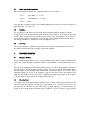
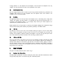
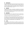
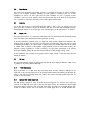
®
TLAudio
user manual
Ivory 2 Series
5000
GOLD DIAPHRAGM VALVE
CONDENSER MIC & PREAMP
TL Audio Ltd, Letchworth, Herts, SG6 1AN, UK
email: [email protected] web: http://www.tlaudio.co.uk
CONTENTS
1.
Introduction
2.
Precautions
3.
Installation
3.1
3.2
3.3
3.4
3.5
3.6
3.7
3.8
3.9
AC Mains Supply
Audio Operating Level
Microphone Input
Balanced Preamp Output
Microphone Out Switch
Unbalanced Monitor Output
Link In and Link Out Connections
Ventilation
Rear Panel
4.
Microphone Operation
4.1
4.2
4.3
4.4
4.5
4.6
Microphone Overview
Warm Up Period
Elastic Suspension Mount
Pop Shield
10dB Pad
120Hz Low Cut Filter
5.
Preamp Operation
5.1
5.2
5.3
5.4
5.5
5.6
5.7
5.8
5.9
5.10
5.11
5.12
Directional Polar Pattern Switch
Omnidirectional response
Cardioid response
Figure-of-8 response
Input Gain
Phase Reverse
Peak LED
Output Level
VU Meter
+10dB Meter Switch
Optional DO-2 Digital Output Card
Link Facility
6.
Specifications
7.
Service
1.
INTRODUCTION
Congratulations on purchasing the Ivory 5000 valve microphone & preamp by TL Audio!
The Ivory 2 Series consists of a range of hybrid valve signal processors, which utilise low noise solid-state
electronics in conjunction with classic valve circuitry to produce units offering very high quality signal paths with
the unique valve audio character. The Ivory 2 Series units offer comprehensive control facilities, whilst remaining
straightforward to operate, and represent excellent value for money.
The 5000 microphone & preamp package consists of a premium quality valve condenser microphone with a 1” gold
diaphragm and an individually matched PSU and discrete microphone preamp. Featuring very low noise and an
exceptionally wide bandwidth, the 5000 PSU/preamp provides continuously variable input and output gain controls,
a phase reverse switch, a selectable 9-position polar pattern switch and a backlit VU meter which monitors preamp
output level.
The microphone itself is shown in Figs.1 & 2. It utilises a single 12AT7 dual triode valve powered from a high
quality stabilised 200V DC supply from the PSU/preamp unit. The microphone is provided with a 10dB pad and a
120Hz low cut filter switch, and comes complete with a 10 metre interconnecting cable, shock mount and foam
pop shield. The block diagram of the PSU/preamp unit is shown in Fig.3. The microphone and preamp are
connected via the supplied 10 metre cable, which carries both the balanced audio output from the microphone and
the power connections for the valve stages of the microphone.
The gain of the preamp input stage is controlled by a continuously variable rotary control providing between 16
and 60dB of gain. A Peak LED indicates internal headroom by illuminating around 6dB before the onset of
clipping. Phase reverse may be applied, before the output level control. The output control itself functions as a
fader by allowing correct matching to the sensitivity of the following equipment (e.g. mixing console or multitrack
machine).
The main preamp output is at balanced +4dBu line level, although the adjacent “Mic out” switch allows the
preamp stage to be completely bypassed so that a low level mic signal is provided on the main output, allowing
connection to a different choice of mic preamp if desired. The 5000 preamp also has an extra unbalanced line
level output entitled “Monitor”. This output duplicates the main preamp output and is ideal for monitoring the
preamp signal directly, thus avoiding latency problems (delays) when using digital-based recording systems.
The optional DO-2 digital output card can be fitted to the preamp which provides a 24bit SPDIF output at
44.1/48kHz. If two 5000 microphone/preamps are used - and the ‘Link Out’ connector from the first preamp is
connected to the ‘Link In’ of the second - then a single DO-2 card fitted to the second preamp will provide a
stereo SPDIF signal consisting of the two preamp outputs panned hard left and right - in this way a stereo pair of
microphones can be outputted directly in digital format.
Please read this manual fully before installing or operating the 5000 microphone & preamp.
FIG 1: FRONT OF MICROPHONE
FIG 2: REAR OF MICROPHONE
120Hz LOW
CUT FILTER
CONNECTION TO 5000 PSU/PREAMP
10dB PAD
FIG 3: BLOCK DIAGRAM
2.
PRECAUTIONS
The 5000 microphone and preamp require very little installation, but like all electrical equipment, care must be
taken to ensure reliable, safe operation. The following points should always be observed:
- All mains wiring should be installed and checked by a qualified
Electrician,
- Ensure the correct operating voltage is selected on the rear panel
before connecting to the mains supply,
- Never operate the unit with any cover removed,
- Do not expose to rain or moisture, as this may present an electric
shock hazard,
- Replace the fuse with the correct type and rating only.
Warning: This equipment must be earthed.
3.
INSTALLATION
3.1
AC Mains Supply.
The unit is fitted with an internationally approved 3-pin IEC connector. A mating socket with power cord is
provided with the unit, wired as follows:
Brown:
Blue:
Live.
Neutral.
Green/Yellow: Earth (Ground).
All mains wiring should be performed by a qualified electrician with all power switched off, and the earth
connection must be used.
Before connecting the unit to the supply, check that the voltage selector switch on the rear panel is correctly set.
The unit may be set for 115V (accepting voltages in the range 110V to 120V, 60Hz AC), or to 230V (for voltages
in the range 220V to 240V, 50Hz AC). Adjustment to the operating voltage should be made by sliding the selector
switch up or down with a small screwdriver until the desired voltage is displayed. The mains fuse required is 20mm
anti-surge, 1AT rated at 250V. If it becomes necessary to replace the fuse, only the same type and rating must be
used. The power consumption of the equipment is 20VA.
Warning: attempted operation on the wrong voltage setting, or with an incorrect fuse, will invalidate the warranty.
3.2
Audio Operating Level.
The 5000 preamp is equipped with outputs suitable for connection to a wide variety of other audio equipment such
as multitrack recorders and mixing desks. Generally, the balanced XLR output connector will be required for
interfacing to other professional equipment, where the operating level (line-up level or nominal level) will be
+4dBu, or about 1.2V rms.
The unbalanced “Monitor” jack connector is an unbalanced duplicate of the main preamp output and has an
operating level of -2dBu. This output is designed to feed an alternative recorder or for monitoring purposes.
Both the balanced and unbalanced outputs may be used simultaneously if required. Balanced interconnection is
always preferable to obtain the best headroom and noise rejection, but can only be used if the other equipment in
the chain, e.g. the recorder or mixing console, also has provision for balanced connections.
3.3
Microphone Input.
The microphone is connected to the PSU/Preamp via a 7 pin XLR type connector. A matching 10 metre cable is
supplied that connects the microphone to the preamp, with the following pin wiring:
-
Pin
Pin
Pin
Pin
Pin
Pin
Pin
1
2
3
4
5
6
7
=
=
=
=
=
=
=
Valve HT supply
Valve heater + supply
Polar Pattern Bias
Ground
Mic – output signal
Mic + output signal
Ground
This connector is designed only to interface with the Ivory 5000 microphone - do not attempt to connect any
other microphones via this connector, or damage may result to both microphone and/or preamp. Also ensure that
the microphone and preamp are connected to eachother before powering up the preamp.
The 10 metre cable provided is the maximum length that is recommended to connect the microphone and preamp
- using longer cables will almost certainly compromise the noise performance of the system.
3.4
Balanced Preamp Output.
The line level output is via a balanced, 3 pin male XLR connector. The mating connector should be wired as
follows:
- Pin 1 = Ground (screen),
- Pin 2 = Signal Phase (“+” or “hot”),
- Pin 3 = Signal Non-Phase (“-” or “cold”).
3.5
Microphone Out Switch.
Adjacent to the preamp output is the ‘Mic Out’ switch, which bypasses the entire 5000 preamp stage and connects
the low level unamplified microphone signal directly to the 5000 preamp output socket. This output socket can
then be connected directly to the mic input connector of an external preamp or vocal processor, enabling the user
to employ his own choice of preamp stage if preferred. In this mode the controls of the 5000 preamp become
inactive, as does the Monitor output and the feed to the optional DO-2 card. The connections remain the same as
those detailed in 3.4: only the signal level changes.
3.6
Unbalanced Monitor Output.
An unbalanced line output is provided on a 0.25” mono jack socket.
- Tip =
- Screen =
Signal Phase (“+” or “hot”).
Ground.
This output functions simultaneously with the balanced output, and is designed as an extra feed for recording or
monitoring purposes.
FIG 4: POLAR AND FREQUENCY RESPONSE (CARDIOID MODE)
0°
0
330°
30°
-10
300°
60°
-20
270°
90°
120°
240°
150°
210°
180°
(dB)
20
10
0
-10
-20
-30
20 Hz
50
100
200
500
1k
2k
5k
10k
20k
3.7
Link In and Link Out Connections.
Both these connections are provided on a separate balanced 0.25” stereo jack socket:
- Tip =
Signal Phase (“+” or “hot”).
- Ring =
Signal Non-Phase (“-“ or “cold”).
- Screen =
Ground.
These connections are provided to allow a pair of 5000 microphone/preamp systems to be used with a single DO-2
digital output card - see section 5.12.
3.8
Ventilation.
The unit generates a small amount of heat internally. This heat should be allowed to dissipate by convection
through the grills in the side panels and front panel, which must not be obstructed. Do not locate the unit where
it will be subject to external heating, for example in the hot air flow from a power amplifier, or on a radiator. If
used free standing, ensure that the equipment is protected against rain and spillage of liquid. The 5000 may be
free standing, or mounted in a standard 19” rack via the supplied rack ears.
3.9
Rear Panel.
The rear panel connectors are identified in Fig.6. Make sure that all settings, mains and audio connections have
been made as described above before attempting to operate the equipment.
4.
MICROPHONE OPERATION
4.1
Microphone Overview.
The Ivory 5000 microphone employs a large 1” dual gold diaphragm, which enables a variety of directional polar
patterns to be selected. The polar and frequency responses for the microphone in cardioid mode are shown in Fig.
4.
The ‘front’ of the microphone for normal cardioid pickup settings (i.e. the side of the microphone that would face
the sound source), is where the TL Audio logo badge is situated - however, by altering the directional polar pattern
from the preamp, the dual diaphragm allows omnidirectional and figure-of-8 patterns to be selected, with 6
intermediate positions. On the rear of the microphone a high pass filter switch rolls off low frequencies below
120Hz at a slope of 6dB per octave. There is also a –10dB switch for padding down the output of the microphone
in situations where the source signal has a very high sound pressure level.
4.2
Warm Up Period.
It is important that the microphone/preamp is allowed to reach its natural working temperature before use. The
12AT7 valve within the microphone is heated using a current limiting circuit - this ensures that the valve is not
over-stressed but also means that the valve heater voltage is gradually ramped up to its normal working level.
Because of this we would normally recommend that the microphone is left for 15 minutes to warm up before
recording commences. It is also important that the microphone is stored at normal room temperature and in dry
conditions, since cold and moisture can affect the noise performance of the capsule.
4.3
Elastic Suspension Mount.
Use of the supplied suspension mount is advised to prevent strong mechanical vibrations being transmitted to the
microphone, either from the air or the microphone stand. The suspension mount can be attached to the
microphone stand via the threaded adaptor.
4.4
Pop Shield.
The supplied pop shield fits over the top section of the microphone and is a useful filtering device to help prevent
“sibilance” and “popping” side effects. Sibilance is an undesirable side effect where the pronounced letter “S” is
accentuated by the microphone. Popping is a low frequency thump caused by the extreme expulsion of air
experienced by the pronounced letters “B” or “P”.
Another important role of the pop shield is in protecting the microphone diaphragm from contamination through
moisture, food and smoke particles exhaled by the performer, particularly in close-miked situations.
4.5
10dB Pad.
The 10dB pad is located on the rear face of the microphone, allowing the engineer to access the switch without
having to obstruct the performer, who will be facing the front face of the microphone. The pad reduces the
sensitivity of the microphone by 10dB, thus allowing the microphone to cope with very high sound pressure levels
such as those produced by percussive instruments or the close miking of powerful vocalists.
4.6
120Hz Low Cut Filter.
The Low Cut Filter Switch is also located on the rear face of the microphone, and filters signals below the 120Hz
cut-off frequency at a rate of 6dB per octave. This restricts the low frequency response of the microphone, to
effectively remove rumble or LF noise from the signal. The filter can be useful in restricting “popping” on vocals or
even low frequencies caused by contact with microphone stands or microphone cables. Popping is described in
section 4.4, and since it contains a lot of low frequency content, the low cut filter can help to reduce the problem
along with the use of a pop shield.
5.
PREAMP OPERATION
The layout of the 5000 preamp front panel is shown in Fig.5.
5.1
Directional Polar Pattern Switch.
The 5000 preamp is provided with a 9 position variable polar pattern switch, which allows omnidirectional, cardioid
and figure-of-8 pick-up patterns to be selected, along with 6 intermediate positions.
FIG 5: FRONT PANEL
DETACHABLE
RACK EARS
PREAMP SECTION
OUTPUT SECTION
FIG 6: REAR PANEL
SLOT FOR OPTIONAL DO-2 CARD
IEC INLET
MONITOR OUTPUT
LINK CONNECTORS
PREAMP OUTPUT
CONNECTION TO MICROPHONE
5.2
Omnidirectional response.
In this position the diaphragm responds equally to sound pressure changes irrespective of which direction they are
coming from, so this setting is useful for recording sources where plenty of room ambience is desirable in the
recorded sound. This might include choral or organ music where the acoustics of the recording location are integral
to the quality of the recording. Some engineers find the omni position can yield a better sound quality and bass
response, but the disadvantage can be that once the room ambience is captured on the recording it can’t be
removed. For this reason the cardioid pattern is often a more popular choice for pop or rock recordings, where
reverb can be electronically controlled during the mixing process.
5.3
Cardioid response.
The cardioid position can be thought of as the combination of an omnidirectional and a figure-of-8 pattern
superimposed upon eachother. This yields a very directional pattern whereby sound at the rear of the microphone
is rejected in favour of sound arriving from the front. This makes the cardioid pattern ideal for recording sources
where the room ambience is largely rejected and a dry sound is captured. Vocals are typically recorded using the
cardioid characteristic since this dry quality gives the engineer the ability to really control the vocal and ensure
that it sits at a comfortable level within the overall mix.
5.4
Figure-of-8 response.
The figure-of-8 position responds to differences in sound pressure between either side of the microphone capsule, so
sounds received from the front and back of the microphone will be the strongest, with sounds from either side
being largely rejected. This response can be useful when recording two vocalists together, enabling each to perform
on either side of the microphone and allowing some visual interaction between each artist.
Another application for this response is in the MS recording technique. This involves using two microphones – one
set to any pattern (from omni to highly directional) and pointed at the centre of the sound source (the ‘M’ or Mid
signal) , while the other is set to figure-of-8 and has its positive recording axis pointing to the left of the sound
source, but at a right angle (the ‘S’ or Side signal). Mixing the two resultant microphone outputs together in phase
yields the left channel signal, and mixing them out of phase provides the right channel signal (this process is
known as ‘matrixing’). There are a number of advantages in using the M-S technique, including the ability to easily
alter the width of the stereo signal by varying the amount of ‘S’ level in the playback signal.
5.5
Input Gain.
The gain of the input stage is continuously variable from +16 to +60dB. This is a very wide range, to cater for
all types of recording situations, but care must be taken not to apply large, sudden changes in gain as this may
result in unexpectedly large output signals. Start with the 5000 input gain control set to minimum, and the output
level control at the mid-point (12 o’clock position). The input gain can then be gradually increased until the 5000
VU meter reads 0VU on normal signal level. The output level control should then be adjusted to produce the
required output.
5.6
Phase Reverse.
This switch reverses the polarity of the preamp signal and is a correctional function either for incorrect microphone
wiring or for out-of-phase microphone positioning. The latter problem is encountered when two or more
microphones are used on the same signal source and phase cancellation can occur. A symptom of phase
cancellation is often a loss of low frequency content, but incorrect phase may not be obvious to an inexperienced
ear. It is possible to verify correct phase using a device called a phase correlation meter.
5.7
Peak LED.
The red Peak LED operates as a conventional warning that clipping is about to occur. The operating level of the
entire signal chain is monitored, and the LED illuminates when there is less than 6dB of headroom remaining.
Normal operation would be to set the input gain so that occasional lighting of the Peak LED occurs on transients.
5.8
Output Level.
The output level control acts as a continuously variable output fader, and simultaneously feeds the balanced preamp
output, the monitor output and the optional DO-2 digital output (if fitted).
At the fully anticlockwise (minimum) setting the output level control provides complete level attenuation, thus
effectively muting the output. The centre point of the level control is the 0dB setting (unity gain), with up to 15dB
of additional gain available as the control reaches its maximum setting. The maximum output level of the preamp
is +26dBu, which is sufficient to fully modulate a digital multitrack recorder for direct-to-disk recording. This
technique is gaining in popularity as a means of recording a very high quality signal directly to the recording
device, thus completely avoiding the noise and colouration added by recording through a mixing console.
In other applications, such as feeding into an analogue console or signal processor, a much lower output level will
normally be sufficient.
5.9
VU Meter.
The large backlit VU meter monitors the preamp output level and will show a reading of 0VU when +4dBu of level
is generated at the preamp’s balanced XLR output.
5.10
+10dB Meter Switch.
Below the VU meter is a ‘+10dB’ switch. This switch simply reduces the meter reading by 10dB (but not the
signal level) so that very high output levels can be accurately monitored without fully deflecting the VU needle. This
setting is often used when recording directly into a DAW or HD recorder, where high preamp output levels are
necessary to drive the recorder.
5.11
Optional DO-2 Digital Output Card.
The 5000 preamp is designed to accept the optional D0-2 24 bit digital A to D converter card to allow easy
interfacing of the 5000 with devices such as sound cards and digital recorders. The card feeds the converted 5000
mono preamp output to both sides of the stereo SPDIF phono output. The sample rate is switchable between either
44.1kHz or to 48kHz, and the card can be clocked to an external digital source via the BNC wordclock input.
When clocking the DO-2 to an external source the sample rate setting on the DO-2 needs to be set to match the
external sample rate, otherwise correct locking may not occur and audible clicking may appear on the digital
output. In terms of gain, the DO-2 will generate a signal level of 0dBfs in the digital domain when +18dBu of
output level is generated at the balanced line output of the 5000 preamp.
5.12
Link Facility.
The ‘Link In’ and ‘Link Out’ jack connectors are designed to allow a pair of 5000 mic/preamps to be used in
conjunction with a single DO-2 card, thereby providing a stereo pair of microphone outputs in 24 bit digital
format. The DO-2 card is fitted to the second preamp only, and the ‘Link Out’ connector of the first preamp is
connected to the ‘Link In’ of the second preamp via a balanced stereo jack cable. See Figure 7.
The DO-2 thus carries both microphone signals, panned hard left/hard right on a single digital SPDIF connector.
This set-up is ideal for recording a stereo pair of 5000 mics directly into a 2-T DAT or CD-R machine (i.e. stereo
location recording) or onto pair of tracks on a DAW to create a stereo image of the source being recorded.
In this mode the relative level from each preamp fed into the DO-2 card is controlled by the output level control
of that particular preamp, so care may be needed in accurately balancing the levels from both preamps to create
an even stereo image.
MIC 1
MIC 2
In
In
DO-2 CARD
PREAMP 1
PREAMP 2
LINK OUT
LINK IN
PREAMP 1
STEREO TRS JACK-TO-JACK
CABLE
SPDIF STEREO
DIGITAL OUTPUT
FIG 7: LINK FACILITY
6.
SPECIFICATIONS
Microphone:
Directional Pattern:
9 positions from Omni, via Cardioid through to Figure-of-8.
Sensitivity:
14mV/Pa = -37dB (0dB = 1V/Pa).
Frequency Response:
20Hz – 20kHz.
Low Cut Filter:
120Hz @ 6dB/octave.
Impedance:
Less than 300 Ohms.
Max SPL:
130dB (1kHz, 1% THD).
Equivalent Noise:
18dB-A (IEC 268-4, A weighted).
SNR:
76dB (ref: 1 Pa).
Dimensions:
190mm length, 59mm diameter.
Net Weight:
700g.
PSU/Preamp:
Microphone Input:
Input impedance greater than 2kohm.
Gain range +16dB to +60dB.
Noise -127dBu (EIN with 150 ohm source, 22Hz – 22kHz 60dB gain).
7-pin female XLR connector to supplied cable only.
Input Gain Range:
+16dB to +60dB, continuously variable.
Output Gain Fader:
Centre detent at 0dB, max gain +15dB.
Outputs:
Balanced XLR, nominal level +4dBu, max level +26dBu,
Unbalanced monitor jack, nominal level –2dBu, max level +20dBu.
Link Facility:
Balanced jack Link in and Link out sockets, +4dBu nominal level, allows connection to channel
2 of optional DO-2 digital output card.
Peak LED:
Monitors pre and post output fader, threshold +20dBu ref balanced XLR output (6dB prior to
clipping).
Meter:
Illuminated VU meter, 0VU = + 4dBu ref balanced XLR output. 10dB meter pad switch.
Frequency Response:
20Hz to 35kHz, +0, -2dB (20dB gain).
Dimensions:
2U case, with supplied rack ears.
483mm wide x 88mm high x 200mm deep (19” x 7.9” x 3.5”) rack mounting.
432mm wide x 88mm high x 200mm deep (17” x 7.9” x 3.5”) free standing.
Power Requirements:
Rear panel selectable for 220-240V 50Hz or 110-120V 60Hz
operation.
Rear panel fuse 20mm, 1AT, 250V.
Power consumption 20VA typical.
Detachable 3 pin IEC connector, mating connector and cable supplied.
Front panel On/Off switch with green LED.
Shipping Weight (includes microphone, preamp and all accessories):
8kgs (17.6lbs).
The above specifications are typical figures, and are subject to change without notice.
7.
SERVICE
Should the 5000 microphone or preamp require service, it must be taken or posted to an authorised dealer. Please
retain the original packing for possible future use, and ensure the unit is suitably protected during transit. The
manufacturer cannot accept responsibility for damage caused during transportation.
The microphone and preamp are supported by a limited warranty for a period of one year from the date of
purchase. During this period, any faults due to defective materials or workmanship will be repaired free of charge.
The warranty excludes damage caused by deliberate or accidental misuse, operation on the incorrect mains voltage,
or without the correct type and value of fuse fitted. It is the user’s responsibility to ensure fitness for purpose in
any particular application. The warranty is limited to the original purchase price of the equipment, and excludes
any consequential damage or loss. If claiming repair under warranty, please enclose proof of purchase date.
Please record the following details:
Serial Number.............................
Date purchased...........................
Dealer.........................................