1
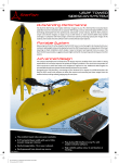
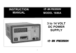
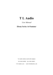
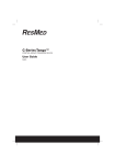
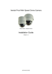
Contents
1 Feature.................................................................................... 1
2 Specification........................................................................... 1
3 Installation Instruction............................................................ 2
3.1 Installation Preparation................................................ 2
3.2 DIP Switch Setup......................................................... 3
4 Installation.............................................................................. 4
4.1 Installation Type...........................................................4
4.2 Installation Steps..........................................................4
4.3 System Connection...................................................... 5
5 Operation................................................................................ 7
5.1 PTZ Control................................................................. 7
5.2 Preset Setting............................................................... 7
5.3 Call Presets...................................................................7
5.4 Lens Control.................................................................7
5.5 Auto Scan Control........................................................8
5.6 Auto Tour Scan.............................................................8
5.7 IR Far/Near Light Switch.............................................8
5.8 Error Correction for Presets......................................... 9
5.9 Restore Factory Setting................................................9
6 RS485 Data Cable Connection............................................... 9
7 Appendix............................................................................... 10
1 DIP Switch setup...........................................................10
II Shortcuts Operation......................................................15
8 Trouble Shooting.................................................................. 17
1 Feature
* OSD English Menu.
* 128 preset positions.
* 8 tours, 16 presets/ tour.
* Aluminum alloy structure.
* IR Distance: 130meters.
* 360° continuous rotation.
* Pan/Tilt Speed 0.5°~20°/sec.
* Lighting proof and surge proof.
* Auto running memory against power outage;
* Support multi-protocols: Pelco D/P, Sony, LG, CNB etc.
* Support linear scan, scan speed: 6°/9 °/15°/20° adjustable.
* IR LEDs and Lens are always synchronized, no blind monitor position.
2 Specification
Model
IR Variable Speed Dome Camera
Power Supply
Output: DC12V±5%,5A; Input:AC100V~240V
50/60Hz
Power (Max.)
15VA(IR Off) 36VA(IR On)
Output Voltage
DC12V
Pan/Tilt Speed
0.5°~20°/sec
Pan Range
0°~360°Continuous
Tilt Range
0°~90°
IR Far Light switch
6 times (default), setup in personal
Preset
128 presets, 8 tours, 16 presets/tour
Line Scan
4, speed could be adjustable (6°,9°,15°,20°/sec)
1
Protection
70°C±3°C
Temperature
Communication
RS485
Protocol
Pelco-P/D auto detected
Baud Rate
2400bps,4800bps,9600bps,19200bps
Address Code
255
Working
Indoor: 0°C~50°C Outdoor: -30°C~50°C
Temperature
Humidity
<90%
Carton Diameter
31x31x45cm
3 Installation Instruction
3.1 Installation Preparation
A. Only qualified and experienced person can carry on this installation.
B. Please refer to installation instructions.
C. Speed dome installation is sure to use clean gloves, please avoid using
metal, hard objects or hands directly touch the down cover.
D. After installation, please use soft towel to clean the down cover when
necessary. The acid sweat mask of fingerprint will corrode the coating of
down cover and scratch on down cover will cause vague images.
E. Please check all parts are complete before opening the package.
F. Please check the space and toughness of the site before installing.
G. Please use reliable tools, e.g. screw driver, and spanner. Also please check
the DIP switch setting is correct.
2
3.2 DIP Switch Setup
(1) Detach the upper housing and bottom cover, you can see DIP switch
.
(2) Baud Rate Setup
Decoder Switch: 9~10 (1=ON,0=OFF)
Baud Rate
Switch 9~10 setting
Max transmission distance (M)
9
10
2400BPS
0
0
1800
4800BPS
1
0
1200
9600BPS
0
1
800
19200BPS
1
1
600
Notice: please restart the camera after setting switch
switch..
3
4 Installation
4.1 Installation Type
There are 2 types of installation.
(1) Wall Mount. (Standard configuration)
(2) Suspended Mount. (Optional)
4.2 Installation Steps
A. Please take the wall bracket as a template to mark the screw positions of
the four location holes. Drill the holes and put the supplied screw inside.
The dimension of the holes as followed:
Wall Mount
4
Suspended Mount
B. Take out the cables (power cable, video cable, control cable and
combination cable) through the bracket base and upper housing, and leave
enough length of the cable.
C. Then fasten the wall bracket by using nuts, spring washers and flat
washers.
D. Please clean up the stains on the dome cover after installed.
4.
4.33 System Connection
(1) According to the label on the main connection line, Please connect the
power cable, video / control cable correctly, connect RS485 cable to its
corresponding cable connector, and then connect the cable connector to its
socket. The connection is as below: (The power cable should be dealing with
5
waterproof.)
(2) Fix the bracket to the Power Base.
(3) Connect the control system and display device as the picture of System
Connection shows.
Note: please swathe the waterproof belt to the connector if you install
outside
outside.
6
5 Operation
5.1 PTZ Control
Control the dome direction by joystick of keyboard, the default speed is
0.5°~20°/Sec and adjustable.
5.2 Preset Setting
IR Variable Speed Dome Camera can set 128 presets, support lens preset. Part
of preset for special purpose can not be edited, as control order.
Turn the camera lens to the area to be supervised, and zoom to proper position,
settings
firstly input the presets, and then press the Presets on the keyboard (settings
differ in different control methods
methods).
For instance, operation for # 1 Presets on keyboard is to turn the camera lens
to the area to be supervised, and input “1” on the keyboard, and then press
Presets button (such as “S-PRESET”), and the # 1 Presets has been well set.
5.3 Call Presets
Firstly input the Presets number on the keyboard, then press the “Call Presets”
button, the intelligent Dome will rotate to the Presets that has been previously
set after the operation (Call methods varies in different control methods)
For instance, Call for # 1 Presets on the keyboard, firstly input “1” on the
keyboard, and then press the Call Presets button (such as “PRESET”) , and the
intelligent will rotate to the Presets that has been previously set.
5.4 Lens Control
A. Use “TELE” and “WIDE” key to control the zoom (Telephoto or
Wide-angle).
B. Use “FAR” and “NEAR” key to control the focus (Manual/ Auto).
Notice: do not use Focus under the below conditions.
�
The target is not in the center of the picture.
�
View near and far picture at same time.
�
The target is too dark.
7
�
Too strong high light or back light.
�
The target move too fast.
C. Iris control: Auto
For manual control, please use the “OPEN/CLOSE” key on the keyboard to
control the Iris.
5.5 Auto Scan Control
Set left limit position (#35 preset), right limit position (#36 preset); if the
position is the same, the camera rotate 360° continuous when auto scan, then
setup the pan scan speed (the method as follow), call#38 preset or auto key
begin auto scan.
Use #38 preset to delete the auto scan.
Setup the auto scan speed:
Pan Speed
Setup Order
Tilt Speed
Setup Order
6°/Sec
Call #61 preset
9°/Sec
Call #62 preset
15°/Sec
Call #63 preset
20°/Sec
Call #64 preset
5.6 Auto Tour Scan
The dome camera support auto tour scan.
For the shortcut operation of tour scan presets, take the appendix II as
reference.
5.7 IR Far/Near Light Switch
(1) Setting the optical zoom of lens when IR Far/Near Light Switch. Range
from 1~the max. Optical zoom of camera module. The default is 6X.
(2) Switch method (should camera module support): Adjust to the optical
zoom one wants, and then sett #246 twice.
5.8 Error Correction for Presets
For various reasons, the Dome may have the Presets deviation, and the Dome
can correct its error by Call #34 preset.
8
5.9 Restore Factory Setting
Call #40 preset restore to factory defaults.
6 RS485 Data Cable Connection
A. We suggest using chain connection or bus connection. The cable length
keeps in 7 meters if you use bus connection.
B. Regarding 120Ω resistances: once the communication distance is more than
300 meters you have to add a terminal resistance in the farthest terminal of
485 cables. When the device quantity is less than 22 pieces, you could not add
the resistance. Just change the jumper cap on the decoder board from jump pin
1 and 2 to pin 2 and 3 to enhance the resistance.
C. Max 32 device can be connected without control code distributor. If you
need more devices, an extra distributor will be needed.
D. Farthest distance of RS485 communication cable is 1800 meters, Due to
different baud rate, transmission distance will be different. For longer
transmission distances, an extra control code distributor or amplifier will be
needed.
E. In order to avoid the interference, please keep the RS485 cable away from
high voltage cable and separate from other power wire.
7 Appendix
I DIP Switch setup
K1 DIP switch is an address switch, consist of 8 number, use 8421 binary
code, max 255 address. When the switch is in the “ON” position, the number
from 1~8 corresponding to 1,2,4,8,16,32,64,128. For example, if you set
1,3,5,7 switch to the “ON” position, the corresponding address will be
1+4+16+64=85. please refer to below details.
1=ON, 0=OFF
Sheet 1(1=ON,
0=OFF)
9
DIP switch
K1 ID Switch(number 1-
DIP switch
number 8)
Address
K1
ID
Switch(number
1-
number 8)
3
4
5
6 7
8
Address
1
2 3
4
5
6 7
8
0 0
0
0
0 0
0
2
0
1 0
0
0
0 0
0
1 2
1
1
3
1 1
0
0
0
0 0
0
4
0
0 1
0
0
0 0
0
5
1 0
1
0
0
0 0
0
6
0
1 1
0
0
0 0
0
7
1 1
1
0
0
0 0
0
8
0
0 0
1
0
0 0
0
9
1 0
0
1
0
0 0
0
10
0
1 0
1
0
0 0
0
11
1 1
0
1
0
0 0
0
12
0
0 1
1
0
0 0
0
13
1 0
1
1
0
0 0
0
14
0
1 1
1
0
0 0
0
15
1 1
1
1
0
0 0
0
16
0
0 0
0
1
0 0
0
17
1 0
0
0
1
0 0
0
18
0
1 0
0
1
0 0
0
19
1 1
0
0
1
0 0
0
20
0
0 1
0
1
0 0
0
21
1 0
1
0
1
0 0
0
22
0
1 1
0
1
0 0
0
23
1 1
1
0
1
0 0
0
24
0
0 0
1
1
0 0
0
25
1 0
0
1
1
0 0
0
26
0
1 0
1
1
0 0
0
27
1 1
0
1
1
0 0
0
28
0
0 1
1
1
0 0
0
29
1 0
1
1
1
0 0
0
30
0
1 1
1
1
0 0
0
31
1 1
1
1
1
0 0
0
32
0
0 0
0
0
1 0
0
33
1 0
0
0
0
1 0
0
34
0
1 0
0
0
1 0
0
35
1 1
0
0
0
1 0
0
36
0
0 1
0
0
1 0
0
37
1 0
1
0
0
1 0
0
38
0
1 1
0
0
1 0
0
39
1 1
1
0
0
1 0
0
40
0
0 0
1
0
1 0
0
41
1 0
0
1
0
1 0
0
42
0
1 0
1
0
1 0
0
43
1 1
0
1
0
1 0
0
44
0
0 1
1
0
1 0
0
45
1 0
1
1
0
1 0
0
46
0
1 1
1
0
1 0
0
47
1 1
1
1
0
1 0
0
48
0
0 0
0
1
1 0
0
10
49
1 0
0
0
1
1 0
0
50
0
1 0
0
1
1 0
0
51
1 1
0
0
1
1 0
0
52
0
0 1
0
1
1 0
0
53
1 0
1
0
1
1 0
0
54
0
1 1
0
1
1 0
0
55
1 1
1
0
1
1 0
0
0
0 0
1
1
1 0
0
57
1 0
0
1
1
1 0
0
58
0
1 0
1
1
1 0
0
59
1 1
0
1
1
1 0
0
60
0
0 1
1
1
1 0
0
61
1 0
1
1
1
1 0
0
62
0
1 1
1
1
1 0
0
63
1 1
1
1
1
1 0
0
64
0
0 0
0
0
0 1
0
65
1 0
0
0
0
0 1
0
66
0
1 0
0
0
0 1
0
67
1 1
0
0
0
0 1
0
68
0
0 1
0
0
0 1
0
69
1 0
1
0
0
0 1
0
70
0
1 1
0
0
0 1
0
71
1 1
1
0
0
0 1
0
72
0
0 0
1
0
0 1
0
73
1 0
0
1
0
0 1
0
74
0
1 0
1
0
0 1
0
75
1 1
0
1
0
0 1
0
76
0
0 1
1
0
0 1
0
77
1 0
1
1
0
0 1
0
78
0
1 1
1
0
0 1
0
79
1 1
1
1
0
0 1
0
95
1
1 1
1
1
0 1
0
81
1 0
0
0
1
0 1
0
82
0
1 0
0
1
0 1
0
83
1 1
0
0
1
0 1
0
84
0
0 1
0
1
0 1
0
85
1 0
1
0
1
0 1
0
86
0
1 1
0
1
0 1
0
87
1 1
1
0
1
0 1
0
88
0
0 0
1
1
0 1
0
89
1 0
0
1
1
0 1
0
90
0
1 0
1
1
0 1
0
91
0 0
1
1
1
0 1
0
92
0
0 1
1
1
0 1
0
93
1 0
1
1
1
0 1
0
94
0
1 1
1
1
0 1
0
95
1 1
1
1
1
0 1
0
96
0
0 0
0
0
1 1
0
97
1 0
0
0
0
1 1
0
98
0
1 0
0
0
1 1
0
99
1 1
0
0
0
1 1
0
100
0
0 1
0
0
1 1
0
101
1 0
1
0
0
1 1
0
102
0
1 1
0
0
1 1
0
56
11
103
1 1
1
0
0
1 1
0
104
0
0 0
1
0
1 1
0
105
1 0
0
1
0
1 1
0
106
0
1 0
1
0
1 1
0
107
1 1
0
1
0
1 1
0
108
0
0 1
1
0
1 1
0
109
1 0
1
1
0
1 1
0
110
0
1 1
1
0
1 1
0
111
1 1
1
1
0
1 1
0
112
0
0 0
0
1
1 1
0
113
1 0
0
0
1
1 1
0
114
0
1 0
0
1
1 1
0
115
1 1
0
0
1
1 1
0
116
0
0 1
0
1
1 1
0
117
1 0
1
0
1
1 1
0
118
0
1 1
0
1
1 1
0
119
1 1
1
0
1
1 1
0
120
0
0 0
1
1
1 1
0
121
1 0
0
1
1
1 1
0
122
0
1 0
1
1
1 1
0
123
1 1
0
1
1
1 1
0
124
0
0 1
1
1
1 1
0
125
1 0
1
1
1
1 1
0
126
0
1 1
1
1
1 1
0
127
1 1
1
1
1
1 1
0
128
0
0 0
0
0
0 0
1
129
1 0
0
0
0
0 0
1
130
0
1 0
0
0
0 0
1
131
1 1
0
0
0
0 0
1
132
0
0 1
0
0
0 0
1
133
1 0
1
0
0
0 0
1
134
0
1 1
0
0
0 0
1
135
1 1
1
0
0
0 0
1
136
0
0 0
1
0
0 0
1
137
1 0
0
1
0
0 0
1
138
0
1 0
1
0
0 0
1
139
1 1
0
1
0
0 0
1
140
0
0 1
1
0
0 0
1
141
1 0
1
1
0
0 0
1
142
0
1 1
1
0
0 0
1
143
1 1
1
1
0
0 0
1
144
0
0 0
0
1
0 0
1
145
1 0
0
0
1
0 0
1
146
0
1 0
0
1
0 0
1
147
1 1
0
0
1
0 0
1
148
0
0 1
0
1
0 0
1
149
1 0
1
0
1
0 0
1
150
0
1 1
0
1
0 0
1
151
1 1
1
0
1
0 0
1
152
0
0 0
1
1
0 0
1
153
1 0
0
1
1
0 0
1
154
0
1 0
1
1
0 0
1
155
1 1
0
1
1
0 0
1
156
0
0 1
1
1
0 0
1
12
157
1 0
1
1
1
0 0
1
158
0
1 1
1
1
0 0
1
159
1 1
1
1
1
0 0
1
160
0
0 0
0
0
1 0
1
161
1 0
0
0
0
1 0
1
162
0
1 0
0
0
1 0
1
163
1 1
0
0
0
1 0
1
164
0
0 1
0
0
1 0
1
165
1 0
1
0
0
1 0
1
166
0
1 1
0
0
1 0
1
167
1 1
1
0
0
1 0
1
168
0
0 0
1
0
1 0
1
169
1 0
0
1
0
1 0
1
170
0
1 0
1
0
1 0
1
171
1 1
0
1
0
1 0
1
172
0
0 1
1
0
1 0
1
173
1 0
1
1
0
1 0
1
174
0
1 1
1
0
1 0
1
175
1 1
1
1
0
1 0
1
176
0
0 0
0
1
1 0
1
177
1 0
0
0
1
1 0
1
178
0
1 0
0
1
1 0
1
179
1 1
0
0
1
1 0
1
180
0
0 1
0
1
1 0
1
181
1 0
1
0
1
1 0
1
182
0
1 1
0
1
1 0
1
183
1 1
1
0
1
1 0
1
184
0
0 0
1
1
1 0
1
185
1 0
0
1
1
1 0
1
186
0
1 0
1
1
1 0
1
187
1 1
0
1
1
1 0
1
188
0
0 1
1
1
1 0
1
189
1 0
1
1
1
1 0
1
190
0
1 1
1
1
1 0
1
191
1 1
1
1
1
1 0
1
192
0
0 0
0
0
0 1
1
193
1 0
0
0
0
0 1
1
194
0
1 0
0
0
0 1
1
195
1 1
0
0
0
0 1
1
196
0
0 1
0
0
0 1
1
197
1 0
1
0
0
0 1
1
198
0
1 1
0
0
0 1
1
199
1 1
1
0
0
0 1
1
200
0
0 0
1
0
0 1
1
201
1 0
0
1
0
0 1
1
202
0
1 0
1
0
0 1
1
203
1 1
0
1
0
0 1
1
204
0
0 1
1
0
0 1
1
205
1 0
1
1
0
0 1
1
206
0
1 1
1
0
0 1
1
207
1 1
1
1
0
0 1
1
208
0
0 0
0
1
0 1
1
209
1 0
0
0
1
0 1
1
210
0
1 0
0
1
0 1
1
13
211
1 1
0
0
1
0 1
1
212
0
0 1
0
1
0 1
1
213
1 0
1
0
1
0 1
1
214
0
1 1
0
1
0 1
1
215
1 1
1
0
1
0 1
1
216
0
0 0
1
1
0 1
1
217
1 0
0
1
1
0 1
1
218
0
1 0
1
1
0 1
1
219
1 1
0
1
1
0 1
1
220
0
0 1
1
1
0 1
1
221
1 0
1
1
1
0 1
1
222
0
1 1
1
1
0 1
1
223
1 1
1
1
1
0 1
1
224
0
0 0
0
0
1 1
1
225
1 0
0
0
0
1 1
1
226
0
1 0
0
0
1 1
1
227
1 1
0
0
0
1 1
1
228
0
0 1
0
0
1 1
1
229
1 0
1
0
0
1 1
1
230
0
1 1
0
0
1 1
1
231
1 1
1
0
0
1 1
1
232
0
0 0
1
0
1 1
1
233
1 0
0
1
0
1 1
1
234
0
1 0
1
0
1 1
1
235
1 1
0
1
0
1 1
1
236
0
0 1
1
0
1 1
1
237
1 0
1
1
0
1 1
1
238
0
1 1
1
0
1 1
1
239
1 1
1
1
0
1 1
1
240
0
0 0
0
1
1 1
1
241
1 0
0
0
1
1 1
1
242
0
1 0
0
1
1 1
1
243
1 1
0
0
1
1 1
1
244
0
0 1
0
1
1 1
1
245
1 0
1
0
1
1 1
1
246
1
0 1
0
1
1 1
1
247
1 1
1
0
1
1 1
1
248
0
0 0
1
1
1 1
1
249
1 0
0
1
1
1 1
1
250
0
1 0
1
1
1 1
1
251
1 1
0
1
1
1 1
1
252
0
0 1
1
1
1 1
1
253
1 0
1
1
1
1 1
1
254
0
1 1
1
1
1 1
1
255
1 1
1
1
1
1 1
1
Notice: some protocols and address start from 0, if you can not control
the dome camera, try to do ±1 of address code.
14
II Shortcuts Operation
Function
Control Method
Tour Scan Stay 2 Seconds
Set #51 preset
Tour Scan Stay 4 Seconds
Set #52 preset
Tour
Set #53 preset
Scan Stay 6 Seconds
Tour Scan Stay 8 Seconds
Set #54 preset
Tour Scan Stay 10 Seconds
Set #55 preset
Left and Right Scan 6°/S
Set #61 preset
Left and Right Scan 9°/S
Set #62 preset
Left and Right Scan 15°/S
Set #63 preset
Left and Right Scan 20°/S
Set #64 preset
st
Start 1 Tour
Call #41 preset (corresponding with
1~16 presets)
nd
Start 2 Tour
Call #42 preset (corresponding with
17~32 presets)
rd
Start 3 Tour
Call #43 preset (corresponding with
65~80 presets)
th
Start 4 Tour
Call #44 preset (corresponding with
113~128 presets)
th
Start 5 Tour
Call #45 preset (corresponding with
129~144 presets)
th
Start 6 Tour
Call #46 preset (corresponding with
145~160 presets)
th
Start 7 Tour
Call #47 preset (corresponding with
161~176 presets)
th
Start 8 Cruise
Call #48 preset (corresponding with
177~192 presets)
15
Set Left Limit position
Setting #35 preset
Set Right Limit position
Setting #36 preset
Start Left and Right Scan
Call #38 preset
Set IR far/near light
Set #246 preset (twice)
Clear Left and Right Limit
Setting #38 preset
position
Preset Error Correction
Call #34 preset
Restore Factory Setting
Setting #40 preset
16
8 Trouble Shooting
Troubles
No action when power on
Reason
Solution
1. The power supply is not
1. Correct the connection.
connected correctly.
2. Check the power supply is
2. The fuse is broken.
connected, or confirms if the
plug connects well.
3. Replace the fuse.
1. The dome DIP switch
1. Reset the DIP Switch according
Self-testing and image are
setting is incorrect.
to the DIP switch chart.
normal but the dome is out
2. RS485 cable is
2. Check 485 bus controls.
of control
disconnected or reversed.
3. Check the wiring.
3. Incorrect RS485 cable
4. Check the control device.
wiring.
1. RS485 communication
1.Connect 120Ω balance resistance.
Some function is out of
signal is not balance.
2. Reset protocol.
control
2. Control protocol is not
compatible.
Unclear image
1. Focus is in manual state.
1. Reset the focus mode to Auto.
2. Extreme zoom
2. Downsize zoom proportion
magnification.
3. Clean the dome cover.
3. Dome cover is dirty.
No night vision
1. Camera is in Color state.
1. Reset the day/night function to
2. backlight on the top or back
Auto.
of the dome camera
2. Remove the direct light source.
17