1
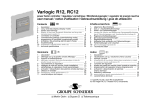
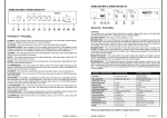
T L Audio
User Manual
PA2 MIC PRE-AMP / DI BOX
Tony Larking Professional Sales Limited,
Letchworth, England.
Tel: 01462 490600. International +44 1462 490600
Fax: 01462 490700. International +44 1462 490700
INTRODUCTION
The T L Audio Mic Pre-Amp / DI Box combines classic valve techniques with low
noise solid state circuitry to produce a unit offering a high quality microphone preamplifier and instrument amplifier on each of its two channels. The microphone inputs
are via balanced XLR sockets with individually switchable 48V phantom power. The
instrument inputs are via unbalanced jack sockets. Channel B also features a phase
reverse switch to correct any phase error when using stereo inputs.
The block diagram of one of the channels is shown in fig.1. A solid state,
electronically balanced input amplifier is used on the microphone input, to achieve
state of the art performance with very low noise, low distortion and wide bandwidth.
The mic input is suitable for low impedance (150-600 ohm) microphones, with a gain
control range of +10 to +60dB. When selected to microphone input, the second stage
amplifier is one half of an ECC83/12AX7 twin triode valve, providing the character of
valve technology whilst retaining a very high quality signal path.
The instrument amplifier consists of two stages of valve amplification. The input is
switchable for optimum impedance and gain for guitar or keyboard inputs. A variable
intensity peak LED glows at the onset of valve compression, becoming increasingly
bright as the degree of overdrive is increased. A Thru’ socket provides a convienient
connection to a backline amplifier or foldback mixer, etc. The DI box is also equipped
with a ground lift switch, which can be used to decouple ground loops.
A solid state, balanced output stage completes the signal path by providing a high
drive capability, switchable for mic or line level, and suitable for connection to
virtually any mixing console, amplifier or PA system.
Please read this manual fully before installing or operating the Pre-Amp / DI Box.
PRECAUTIONS
The T L Audio Pre-Amp / DI Box requires very little installation, but like all electrical
equipment, care must be taken to ensure reliable, safe operation. The following points
should always be observed:
- All mains wiring should be installed and checked by a qualified
electrician,
- Ensure the correct operating voltage is selected on the rear panel
before connecting to the mains supply,
- Never operate the unit with the cover removed,
- Do not expose to rain or moisture, as this may present an electric
shock hazard,
- Replace the fuse with the correct type and rating only.
Warning: This equipment must be earthed.
INSTALLATION
AC Mains Supply.
The Pre-Amp / DI Box is fitted with an internationally approved 3 pin IEC connector.
A mating socket with power cord is provided with the unit, wired as follows:
Brown: Live.
Blue:
Neutral.
Green/Yellow: Earth (Ground).
If the mains cable and plug supplied is not suitable for use in the country where the
unit is to be operated, please consult your dealer. All mains wiring should be
performed by a qualified electrician with all power switched off, and the earth
connection must be used.
Before connecting the unit to the supply, check that the voltage selector switch on the
rear panel is correctly set. The unit may be set for 115V (accepting voltages in the
range 110V to 120V, 60Hz AC), or to 230V (for voltages in the range 220V to 240V,
50Hz AC). The fuse required is 20mm anti-surge, 1AT. The voltage range can be
adjusted by using a small screwdriver to slide the selector switch upwards for 115V
operation, or downwards for 230V operation.
Warning:
attempted operation on the wrong voltage setting, or with an
incorrect fuse, will invalidate the warranty.
Audio Inputs.
Each channel has a 3 pin XLR connector for the microphone input. It is compatible
with either balanced or unbalanced signals, when the mating connector is
appropriately wired:
Balanced inputs:
- Pin 1 = Ground (screen).
- Pin 2 = Signal Phase (“+” or “hot”).
- Pin 3 = Signal Non-Phase (“-” or “cold”).
Unbalanced inputs:
- Pin 1 = Ground (screen)
- Pin 2 = Signal Phase (“+” or “hot”).
- Pin 3 = Signal Ground
When using unbalanced signals, the signal ground may be obtained by linking pins 1
and 3 in the mating XLR connector. Good quality screened cable should be used,
particularly for microphone or low level sources, to prevent hum or noise pickup.
Unbalanced Instrument Inputs.
An unbalanced instrument input and through connection is provided for each channel,
on 0.25” mono jack sockets. The mating plugs should be wired as follows:
- Tip =
Signal Phase (“+” or “hot”).
- Screen = Ground.
Outputs.
The outputs are via balanced, 3 pin male XLR connectors. The mating connectors
should be wired as follows:
- Pin 1 = Ground (screen),
- Pin 2 = Signal Phase (“+” or “hot”),
- Pin 3 = Signal Non-Phase (“-” or “cold”).
If an unbalanced output is required, pins 1 and 3 should both be connected to ground.
Ventilation.
The unit generates a small amount of heat internally, mainly due to the valve heaters.
This heat should be allowed to dissipate by convection through the grill in the front
panel, which must not be obstructed. Do not locate the Pre-Amp / DI Box where it
will be subject to external heating, for example, in the hot air flow from a power
amplifier or on a radiator.
Mounting.
The unit may be free standing or mounted in a 19” rack, where it will require 2U of
space. Self-adhesive feet are provided as an accessory for free-standing use, or the
rack mounting ears provided may be fitted.
To fit the rack ears, first ensure that the unit has been disconnected from the mains.
Remove the four screws at one end of the unit, position the rack ear in place and
secure by replacing the four screws. Repeat for the other ear.
Rear Panel.
The mains inlet socket, fuse, voltage selector switch and ground lift switch are located
on the rear panel. All audio connections are on the front panel.
OPERATION.
Front Panel.
The front panel controls are shown in fig.2.
Input Stage.
Ensure that the correct input connector, mic or instrument, is being used and that the
front panel switch is set to the appropriate position. Note that both mic and instrument
inputs may be connected at the same time, but only one is selected.
Mic Input.
Connect the microphone to the XLR socket on the front of the Pre-Amp / DI Box.
+48V phantom power is available at the mic socket, selected by the switch adjacent to
the input socket.
CAUTION: Operation of the phantom power switch, or plugging a microphone in
with phantom power applied, may cause a click or thump in your loudspeakers. To
prevent this happening, ensure that the system gain is set to minimum (e.g. on your
mixing console fader or power amplifier), before operating the switch or plugging in a
microphone.
Instrument Input.
The instrument input is a 0.25” jack socket on the front panel of the unit. The adjacent
switch configures the input stage for optimum response when used with either a guitar
(high gain with very high input impedance), or with a keyboard (moderate gain
available at standard line input impedance). Note that some active guitars have a built
in gain stage with line driver and may therefore be more suited to the keyboard setting
on the Pre-Amp / DI Box.
With mic or instrument input, if the gain required is not known, set the control to
minimum and gradually increase the gain until the required output level is achieved.
Thru’ Connection.
A through connector is located next to the instrument input socket, to provide a
convienient means of making a simultaneous connection to a backline amplifier or
foldback mixing console.
Ground Lift.
Occasionaly, when making unbalanced connection to multiple items of equipment, a
ground loop will be formed via the ground connections of the various units. A ground
loop will appear as mains frequency hum on the audio outputs from the system. If this
occurs, set the ground lift switch on the back panel of the DI box to the “lift” position,
which should break the ground loop.
The ground lift switch disconnects the audio ground from the mains safety ground,
which remains connected to the DI box case, and allows the DI audio ground to follow
the ground potential of the mixing console that the output of the DI box is connected
to.
Peak LED.
The Peak LED is a variable intensity indicator which begins to glow when the valves
pass the threshold at which the characteristic compression starts to occur. This
phenomenon, unique to valve amplification, leads to an increase in the even harmonic
content resulting in a pleasant “warmer” sound, without the harshness associated with
increased odd harmonic content.
If the output level continues to increase the peak LED becomes progressively brighter,
reaching maximum brightness when there is approximately 10dB of headroom
remaining before clipping.
Phase Reverse.
Channel B is equipped with a phase reverse switch, which may be used to correct a
phase error introduced elsewhere in a stereo signal being processed by the Pre-Amp /
DI Box. A phase error typically appears as a loss of low frequency signal content, due
to cancellation of the out of phase signals.
Output.
The output from the DI Box may be connected to the input of a mixing console, power
amplifier or any other balanced or unbalanced input. The DI Box output is low
impedance, switchable to mic or line level. To achieve the optimum noise and
headroom performance make sure that the DI box output level switch is set to mic if
the output is connected to a mic level input, or similarly that the switch is set to line if
the output of the DI box is connected to a line level input.
CAUTION: Never connect the output of the DI Box to the mic input of a console
with phantom power switched on, to avoid any possibility of damage to the output
stage.
SPECIFICATIONS
Mic Input:
Electronically balanced, input impedance greater than
10Kohm, to suit 150-600 ohm microphones.
First stage solid state, second stage triode valve.
48V phantom power available, via switch.
Gain range +10 to +60dB.
Noise (EIN): -127Bu at maximum gain with a 150 ohm
termination, measured 22Hz-22KHz unweighted.
Maximum input level +10dBu.
3 pin female XLR connector.
Instrument Input:
Unbalanced, input impedance 100Kohm (guitar), 10Kohm
(instrument).
Nominal sensitivity for 0dBu output -35dBu (guitar),
-15dBu (instrument).
Two stage, triode valve amplifier.
Unbalanced jack socket input.
Direct wired through connection, also on unbalanced jack.
Outputs:
Electronically balanced, unbalanced compatible.
Output impedance 47 ohms.
Maximum level +26dBu into 10Kohms, +22dBu into 600 ohms.
3 pin male XLR connector.
Switchable output for line level or mic (30dB pad).
Frequency Response:
20Hz to 40KHz, +0, -1dB, mic input at 20dB gain.
Noise:
Mic EIN -127dBu (Maximum gain 22Hz-22KHz, input terminated in
150 ohms).
Distortion:
THD+N:
0.05% at 1KHz, mic input at 20dB gain, 0dBu output.
Power Requirements:
Rear panel selectable for 220-240V 50Hz or 110-120V 60Hz
operation.
Rear panel fuse 20mm, 1AT.
Power consumption 20VA typical.
Detachable 3 pin IEC connector, mating connector and cable
supplied.
Front panel On/Off switch with green LED.
Dimensions:
19” rack mounting, 2U high, with optional rack mount kit fitted.
483mm wide x 88mm high x 205mm deep.
Weight:
3Kg.
In line with a policy of continuous development, the above specifications are subject to change without
notice.
SERVICE
Should the unit require service, it must be taken or posted to an authorised dealer.
Please retain the original packing for possible future use, and ensure the unit is
suitably protected during transit. The manufacturer cannot accept responsibility for
damage caused during transportation.
The unit is supported by a limited warranty for a period of one year from the date of
purchase. During this period, any faults due to defective materials or workmanship
will be repaired free of charge. The warranty excludes damage caused by deliberate or
accidental misuse, operation on the incorrect mains voltage, or without the correct
type and value of fuse fitted. It is the user’s responsibility to ensure fitness for purpose
in any particular application. The warranty is limited to the original purchase price of
the equipment, and excludes any consequential damage or loss.
Please record the following details:
Serial Number.............................
Date purchased...........................
Dealer.........................................