1
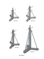
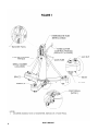
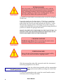
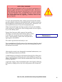
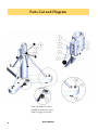
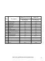
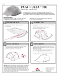
230, 231, 232, and 233 Series
Heavy Duty Mobile Stands
User’s Manual
(Original Instructions)
Instrument
Company
15194 Rev E
Helping the World Measure TM
Since 1927
www.brunson.us
8000 E. 23rd Street
Kansas City, MO 64129
Toll free: 877—MEASURE
(877.632.7873)
Tel: 816.483.3187
Fax: 816.241.1945
For Sales Assistance:
[email protected]
For Repair or Calibration Assistance:
[email protected]
Website:
www.brunson.us
Copyright 2013 Brunson Instrument Company
Table of Contents
Thank you for purchasing
a Brunson Heavy Duty
Mobile Stand. Remember
that our customer support
does not stop after shipment
of a product—we are here
to help you with any
measurement challenges
that you may have.
1
General Information
1
Safety Precautions
3
Unpacking and Setup
3
Moving and Positioning Your Stand
4
Stand Operation
5
Maintenance
6
Parts Diagram and List
8
Declaration of Conformity (CE Mark)
233 Series
231 Series
230 Series
232 Series
User’s Manual
230, 231, 232, & 233 Series Heavy Duty Stands
Congratulations and thank you for purchasing a
Brunson heavy duty mobile stand. We believe that
General Information
our stands are the finest available, providing a rocksolid base to meet all of your metrology needs. We have been in the
measurement industry since 1927, so we fully understand the importance of a stable, rugged, and durable metrology platform. At
Brunson, HELPING THE WORLD MEASURE TM is more than our motto;
it truly reflects our passion and dedication to the metrology world.
Please take a moment to review this manual. It contains important
safety and operational information for the stand. Refer to Figure 1
for part names referenced in the instructions. Finally, for future reference, please record the model and serial number for the stand in
the space provided below.
Model Number _______________________
Serial Number _______________________
Static (non-moving) stability:
a. These stands are designed for use on level surfaces. Operating a stand on non-level surfaces increases the tipping hazard.
Safety Precautions
b. Instrumentation / equipment used with the stand should be centered over the axis of the Intermediate Tube. Extending unbalanced
loads from the centerline axis increases the tipping hazard.
Dynamic (moving) stability:
a. Stands should be moved only when no instrumentation /
equipment is attached and the intermediate tube is in its fully retracted (lowest) position.
b. Stands should be moved by manually pushing or pulling no
faster than a normal walking pace over smooth, level surfaces. Do
not move a stand by pushing or pulling with a powered vehicle.
c. Avoid sudden starts and stops.
These stands are designed for indoor use only. Wind (or other external) loading was not considered when determining stability.
Do not exceed the load capacity of the stand for any attached instrumentation / equipment. The maximum load capacity is listed in
230, 231, 232, and 233 Series Heavy Duty Mobile Stands
1
2
User’s Manual
Table 1.
Table 1
Model
Stand weight
Max load capacity
lbs
Kg
lbs
Kg
230 Series
185
84
150
68
231 Series
158
72
150
68
232 Series
587
267
150
68
233 Series
177
81
150
68
It is the responsibility of
the end user to ensure that
any instrumentation /
equipment attached to the
stand is safely secured.
This is the safety alert symbol. This symbol alerts you to
hazards that can hurt you and others, and/or cause damage
to equipment. Additional information specific to the hazard
will be included with this warning.
WARNING!
Take off the top and sides of the crate by removing the screws. Cut
the three band clamps holding the tribrach legs down. With an
overhead crane (or suitable alternative), lift the stand
off the crate and place on a level surface (refer to TaUnpacking and Setup
ble 1 for stand weights). If a foot pedal is present
(Models 230, 231, and 233), ensure it is not engaged—
the foot pedal should be “up” and free to move.
Adjust the trivet bolts so that the casters touch the floor but do not
bear any weight from the stand. You should be able to swivel each
caster easily by hand. Tighten the jam nut on each trivet bolt.
Ensure that the intermediate tube is in its lowest position and no instrumentation / equipment is attached to the stand.
A foot pedal is used to extend the casters on the 230,
Moving/Positioning Your Stand
231, and 233 Series stands. The 232 Series uses a
handwheel. To extend the casters using the foot pedal, use your
body weight and step on the larger pedal. The locking latch is
spring-loaded and will “click” into place when the stand is locked
onto the casters. For 232 Series Models, turn the handwheel until
the casters extend to the ground.
Manually push or pull the stand into the desired position. The
stand should be positioned so that the tribrach leg on which the
230, 231, 232, and 233 Series Heavy Duty Mobile Stands
3
TIPPING HAZARD
Move the stand over smooth, level surfaces only, with the
intermediate tube in its lowest position and no instrumentation / equipment attached. Move the stand by manually
pushing or pulling (no faster than a walking pace). Do not
tow or push the stand with a powered vehicle.
WARNING!
foot pedal (or handwheel) is mounted points toward the midpoint
of the work.
Lower the stand onto the three trivets. If the floor is something
other than concrete (e.g. wood, tiled, etc.), you may wish to use
pads under the trivets to provide protection for the floor. Lower
the stand by stepping down on the larger foot pedal to take the
weight of the stand and rock your foot downward using the ball of
your foot to release the spring-loaded latch.
MAINTAIN SUFFICIENT PRESSURE ON THE FOOT PEDAL TO
PREVENT THE STAND FROM SUDDENLY DROPPING ONTO
THE FLOOR WHEN THE LATCH IS RELEASED.
CRUSHING HAZARD
Stands are very heavy! Prior to lowering the stand, ensure
area below Tribrach is clear of all obstacles.
WARNING!
TRIPPING HAZARD
Due to the size of the footprint necessary for stand stability,
the legs of the stand can create a tripping hazard.
WARNING!
With the intermediate tube fully retracted, attach the instrument /
measuring equipment to the stand.
Stand Operation
Raise the collar locking handle until the intermediate
tube can be raised easily by rotating the control handles.
To raise the intermediate tube, rotate the control handle counterclockwise (when looking at the hub).
4
User’s Manual
ROTATING HAZARD
The stands are equipped with an air-check mechanism to
prevent rapid descent of the intermediate tube. However,
until sufficient air pressure has built up to slow the descent
of the intermediate tube, considerable force can be exerted
by the free spinning control handle. Therefore, always lower
the intermediate tube by applying a resistive force to the
control handle.
WARNING!
To lower the intermediate tube, release pressure from the ratchet
pawl by slightly raising the intermediate tube, and then retracting
and holding the ratchet pawl away from the rack. Rotate the control handle clockwise to lower the intermediate tube.
When the desired height has been reached, lock the intermediate
tube in place by rotating the collar locking handle down as tightly
as you are able by hand.
Ensure that the trivets fully support the stand by
checking to see that each caster rotates freely. If this
is not the case, loosen the jam nut and adjust the
trivet. After adjusting, ensure that each jam nut is
tight against the tribrach.
Maintenance
The stand is positioned and ready to use.
Upon completion of the job, remove the instrument from the stand,
raise the collar locking handle, and lower the intermediate tube to
the bottom of its travel.
Although the stands were designed for minimal maintenance, two
items will help maximize service life:
A small amount of Neats Foot oil injected through the collar opening on a yearly basis will keep the air cushion leather in good condition. This should be done with the intermediate tube in the fully
extended position.
A periodic wiping of the intermediate tube with a lightly oiled rag
followed by wiping with a dry cloth will preserve the chrome finish.
230, 231, 232, and 233 Series Heavy Duty Mobile Stands
5
Parts List and Diagram
Note: The Model 232 has a
handwheel rather than a foot
pedal to engage the casters.
6
User’s Manual
Item
Models 230, 231, 233
Model 232
Part Number
Part Number
Description
1
Retaining Ring
12938
12938
2
Ratchet Shaft
3646
3646
3
Ratchet Pawl
3625
3625
4
Pawl Spring
3655
3655
5
Pinion
3610
3610
6
Clamping Spoke
3608
3608
7
Hub Screw (not shown)
3611
3611
8
Knob
3566
3566
9
Handwheel Spoke
3568
3568
10
Handwheel Hub
1926
3653-G3
11
Foot Pedal Assembly
17680
N/A
12
Trivet
3649
3840
13
Hex Jam Nut
Comm. 5/8”- 11
Comm. 1”- 8
14
Caster
3658-1
3690
230, 231, 232, and 233 Series Heavy Duty Mobile Stands
7
EU DECLARATION OF CONFORMITY
WITH COUNCIL DIRECTIVE 2006/42/EC
Date of Issue:
Document Ref:
3 June, 2015
15190 Rev 3
Directive:
Machinery Directive 2006/42/EC
Conforming Machinery:
Manually Operated Lifting Stands - Models:
231-MOD Series: up to 26”
231 Series: up to 42”
233 Series: up to 54”
230 Series: up to 67”
232 Series: up to 112”
232-SP Series: up to 40’ (480”)
331 Series: up to 37”
333 Series: up to 50”
330 Series: up to 62”
332 Series: up to 112”
M-Series Adjustable: up to 75”
M-Series Fixed: up to 51”
TetraLock: 400S and 400L Series
810-Series: up to 56”
801-1 Series: up to 51”
5030 Series: up to 52”
5035 Series: up to 17”
237 Series ‘Groundhog’
Manufacturer:
Brunson Instrument Company
8000 E. 23rd St.
Kansas City
MO 64129
USA
Authorised Representative:
Carl Baines
6 Micklehead Business Village
St. Michaels Road
Lea Green, St. Helens
WA9 4YU
United Kingdom
Harmonised Standards
EN ISO 12100:2010, EN ISO 13857:2008,
Referenced or Applied:
ISO/TR 14121-2:2012
Specifications with which Conformity is Essential Health and Safety Requirements of Annex 1 of the Machinery
Declared:
Directive
We hereby certify that the machinery described above conforms with the essential health and safety requirements of
Council Directive 2006/42/EC on the approximation of the laws of the Member States relating to the safety of machinery.
Signed:
Deighton E. Brunson
Signatory:
8
Deighton E. Brunson, President
User’s Manual
15194 Rev E