1
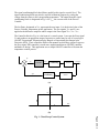
The Controller Output is often subjected to signal conditioning in order to provide the
proper signal level or power as required by the Actuator. If the Actuator is a motor, then
the signal conditioning block may be a power amplifier that generates the appropriate
power to drive the motor.
The use of negative feedback is the key to the proper operation of a control system.
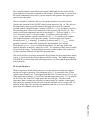
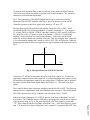
Consider the operation of the ON/OFF control system depicted in Fig. 1b. The object of
the temperature control system described in this paper is to provide air condition
(cooling) control. Suppose that the Controller is OFF (VCO = 0V), providing no cooling.
The operating point is now on the bottom part of the hysteresis curve in Fig. 1b. This
results in increasing temperature and also in increasing VPV. The Error signal VE = VSP −
VPV is decreasing since VSP does not change. VE continues to decrease until VE =
VE(MIN). At this point the controller switches ON (VCO = +5V) and drives the actuator
(fan) in this experiment) which provides cooling. The Error signal now begins to
increase because VPV is dropping. It continues to increase until VE = VE(MAX). At this
point the Controller switches OFF, shutting OFF the fan and the cycle repeats.
The difference VE(MAX) - VE(MIN) is called the dead band. It is the range of the Error
signal in which the controller is either ON or OFF. No regulation of the Process Variable
occurs inside this range. The dead band is necessary because without it the system will
oscillate constantly between ON and OFF operating states.
This article describes a prototype that mimics the operation of a large temperature control
system. A fan is used as the actuator that provides the cooling. The graphical language
of LabVIEW, to be described in the following sections, is used to implement the function
of the controller.
III. System Hardware
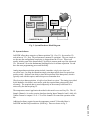
The data acquisition board (DAQ board) serves as the interface between the computer
and the real world as shown by a block diagram in Fig. 2. It is installed in the PC that
operates under Windows 95. In this application MIO-16E -10 board was used. Ch. 0, one
of the analog input channels, is wired to the external temperature sensor. Ch.1 is wired to
the D/A Ch.0, one of the DAC output ports, and also to the fan. Thus the current
temperature data is coming into computer via analog input Ch. 0 and the control signal
that controls the operation of the fan comes from the computer via D/A output Ch.0. In
addition, analog input Ch.1 monitors the operation of the fan as it receives the same
signal from the computer as does the fan.
Page 4.356.4