1
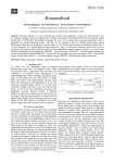
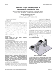
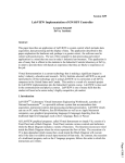
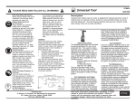
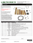
ISSN : 2278 – 1021 International Journal of Advanced Research in Computer and Communication Engineering Vol. 1, Issue 7, September 2012 EMBEDDED OPTIMUM CONTROLLER FOR PROCESS LOOP USING ARM CONTROLLER Sonal J Rane Department of Electrical. Engineering, Faculty of Tech. & Engg., M.S.University of Baroda, Vadodara, Gujarat, India Abstract— Embedded controllers are often the heart of an industrial control system or a process control application. They may also be at the centre of a portable data acquisition system or remote controller that allows an application to keep running even if its umbilical link to the outside world is cut. At the same as control systems is an important application class of embedded systems, feedback control is also an important basic technology that can be employed in the design of embedded real-time systems. Feedback control is a well established and mathematically well-founded theory that is ideal for handling uncertainties.The importance of reducing power consumption in embedded systems has now been widely recognized, and a large body of work has focused on estimating, managing, and reducing power consumption in various system components. For hardware design, techniques have been developed to estimate and optimize power consumption starting from the algorithm and architectural design phases, down to the circuit design and technology optimization steps. Application, semiconductor technology, cost, and time-to-market trends are causing a shift toward increased software content in embedded systems and systems- on-chip. As a result, designers and users of embedded software must be increasingly aware of power issues. While power dissipation is inherently a property of the underlying system hardware, knowledge of the embedded software that runs on the hardware is useful in order to analyze and improve the system’s power-consumption characteristics. Main Objective of this paper is to design a real-time (minimum time) optimum embedded controller for a closed loop process control system for controlling process temperature employing ARM controllers. Keywords— Embedded system, process loops, ARM controller, Optimization method, Control system I. INTRODUCTION The traditional process control systems are computer based systems that control flows, temperatures, pressures etc in the process industry. Before computers, process engineers observed instruments and manually opened and closed valves etc. In some industrial applications, real-time controller tuning is a time-consuming exercise; it can be costly and difficult when there are a multitude of control loops acting on a number of processes and where the complexity of the control problem requires robust and effective controller design. An automated tuning procedure could speed up this activity, but the tuning method should have good properties. An optimization algorithm was developed to provide the optimal controller parameters using a number of integral-error cost functions. The robustness of each cost function was assessed using standard and parametric stability margins. For the class of systems investigated, it seems that exponentially- or timeweighted cost functions can consistently give more robust controller design. The methods for achieving optimum performance are well explored. Establishing the balance between performance and power consumption has been a popular research topic in the past as well. In order to optimize integrated circuit designs, it Copyright to IJARCCE is critical not only for circuit designers to adjust circuit geometries but also for process developers to adjust device characteristics for optimal overall system performance. Asset management and optimization will play an important role in the offerings, since the user’s need of utilizing the capital (assets) is increasing. Adherence to environmental, safety and product regulations will also play important roles in the coming years. This can be seen already today, but not necessarily in the same system offering. Management of information is essential here, and this often means higher levels of complexity. However, other features like safety management demand lower levels of complexity or at least manageable complexity. These are sometimes contradictory requirements and have to me managed. One major challenge is to design systems with new and more functions without letting system complexity increase dramatically. At the end of the day overall reliability is the main requirement for a process control system. An embedded system is a special-purpose computer system designed to perform one or a few dedicated functions, often with real-time computing constraints. It is usually embedded as part of a complete device including hardware and mechanical parts. In contrast, a general-purpose computer, such as a personal computer, can do many different tasks www.ijarcce.com 512 ISSN : 2278 – 1021 International Journal of Advanced Research in Computer and Communication Engineering Vol. 1, Issue 7, September 2012 depending on programming. Embedded systems control many of the common devices in use today. Since the embedded system is dedicated to specific tasks, design engineers can optimize it, reducing the size and cost of the product, or increasing the reliability and performance. Some embedded systems are mass-produced, benefiting from economies of scale. II. DIGITAL TEMPERATURE CONTROL SYSTEM Figure 1 shows the process system, provided with temperature measurement and control of measured temperature with controlled power input. Figure 1 Process Temperature control Block Diagram The temperature sensing element consists of a thermocouple sensor. The task is to implement a controller, to provide temperature control of the process system. It is a practical process control problem in miniature, simulating the conditions found in furnaces boilers, airconditioning systems, etc. The functions within the control loop can be broken down as follows. Sampling of the temperature signal and measurement at an appropriate rate Transfer of the measurement signal to the controller. Comparison of the measured temperature with a stored desired temperature to form an error signal Operation on the error signal by PID algorithm to form an output signal Transfer of the output signal through the hardware to the power control unit. A. Process System The reference input to the temperature control system is fed in the software part. The LCD display unit provides display of the actual temperature of the process system. The temperature range for the system under consideration is 20 to 80 degree centigrade. When a thermocouple is used as temperature sensor, output of thermocouple, in mill volts range is amplified to a range required by A/D converter using instrumentation amplifier. C. Embedded Processor The output of A/D converter is the digital measurement of the actual temperature of the process system. This data is fed to appropriate port pin of controller. The software part compares the actual temperature with the desired temperature at each sampling instant and generates an error signal. D. Control circuit The error signal is then processed as per the control algorithm (to be given later), resulting in a control signal in digital form. The control signal is, in fact, the amount of power required to be applied to the process system in order to reduce the error between the desired temperature and the actual temperature. The power input to the plant (process system) may be controlled with the help of triacs and firing circuit interface. The function of the triac and firing circuit interface is to process the PWM output such that the heater is ON when the PWM output is logic 1, and OFF when it is logic 0. Since the heater is operated off 230v ac at 50 Hz, the firing circuit should also provide adequate isolation between the high voltage ac signals and the low voltage digital signals. To design prototype system using control method through algorithm includes hardware design and firmware design. III. SYSTEM HARDWARE Hardware design starts with the selection of components. Component selection involves selection of microcontroller, serial communication, instrumentation amplifier selection, temperature sensor, power control circuit. Microcontroller selection is important because complete design is based on it. Instrumentation amplifier, temperature sensor plays a vital role for measuring temperature signal and to amplify it. E. System Hardware Block Diagram Below figure 2 shows main block diagram of the system, in which incoming utility side provides 230v, 50 Hz frequency and output parameter temperature of process is controlled through algorithm and power control circuit. B. Temperature sensor Copyright to IJARCCE www.ijarcce.com 513 ISSN : 2278 – 1021 International Journal of Advanced Research in Computer and Communication Engineering Vol. 1, Issue 7, September 2012 System to be controlled PC Power Circuit Power Supply Embedded Circuit Temperature sensor to measure Room Temperature Figure 2 Functional Block diagram of the system F. Selection of controller To control output parameter of process system requires more functionality, more features, cuts cost and minimum time. For expansion in terms of: (I) performance, (ii) memory or (iii) peripherals, we have used Philips-NXP ARM7 controller for faster processing and also for data computation. The purpose to use microcontroller is to convert analog signal into digital as well as digital to analog, to send data to display on the LCD and control various parameters like temperature. 1) Microcontroller Evaluation Board Design: As discussed earlier, microcontroller based design is selected. Now referring to design flow diagram, MCU core design is first step of the actual hardware implementation. To start design with the new controller, first evaluation board is prepared. Verify the design of various test programs GPIO, Timers, Uart, I2C, ADC etc on evaluation board, manufacturer by Keil, shown in figure 3. Using this board check out various routine then combine all routines together. 2) Microcontroller Evaluation Board Design: As discussed earlier, microcontroller based design is selected. Now referring to design flow diagram, MCU core design is first step of the actual hardware implementation. To start design with the new controller, first evaluation board is prepared. Verify the design of various test programs GPIO, Timers, Uart, I2C, ADC etc on evaluation board, manufacturer by Keil, shown in figure 3. Using this board check out various routine then combine all routines together. Copyright to IJARCCE Figure 3 Evaluation board of LPC2146 G. Microcontroller Section Below points describes the information of interfacing of devices with controller. Microcontroller (LPC 2146) core, CPU operating voltage range of 3.0 V to 3.6 V (3.3 V ± 10 %) with 5 V tolerant I/O pads and peripheral require 5V. External clock 12 MHZ and for RTC required 32.768khz crystal Display measured temperature with 3.3V LCD display. To load the program in to microcontroller need the programmer tool. Here we have used Philips utility as programmer. 10 bit, 2 channels ADC is available. Channel ‘1’ is connected to the voltage signal. Timer is used to measure reference temperature usingTMP06. UART is used to serial communication of controller and PC. H. Temperature Sensor There are many temperature sensors available in the market like thermocouple, thermistor, rtd and many more. Thermocouples are the simplest and most versatile temperature transducers available, and using a thermocouple becomes as easy as connecting a pair of wires. While these inexpensive transducers are the most commonly used temperature sensors, Thermocouples are widely used as an inexpensive and fairly accurate way to measure temperature over a wide range of temperatures. Figure 4 shows a typical thermocouple connection. An instrumentation amplifier is used to amplify the small Seebeck voltage before applying the value to an analog-todigital converter. www.ijarcce.com 514 ISSN : 2278 – 1021 International Journal of Advanced Research in Computer and Communication Engineering Vol. 1, Issue 7, September 2012 Low Floating High COLD JUNCTION TEMPERATURE INSTRUMENTATION AMPLIFIER ADC SEE BACK VOLTAGE CONSTANTAN THERMOCOUPLE COLD JUNCTION Figure 4 Thermocouple Connections (Type J) Unfortunately it is not possible to simply connect up a voltmeter to the thermocouple to measure this voltage, because the connection of the voltmeter leads will make a second, undesired thermocouple junction. To measure reference temperature or cold junction temperature, we can use temperature sensor IC TMP06. I. TMPO6 It is monolithic temperature sensors that generate a modulated serial digital output (PWM) which varies in direct proportion to the temperature of the devices. J. Instrumentation amplifier An instrumentation amplifier that has excellent common mode rejection is employed for measurement. This goes hand-in-hand with the use of a grounded junction. A typical instrumentation amplifier circuit is shown below. This circuit arrangement is so commonly used that it is commercially available by that name in single-package units. Note that this circuit is basically a differential amplifier with two additional op-amps to buffer the inputs. Power Supply 1) Functional Description: The output of the TMP05/TMP06 is a square wave with a typical period of 116 ms at 25°C (CONV/IN pin is left floating). The high period, TH, is constant, while the low period, TL, varies with measured temperature. The output format for the nominal conversion rate is readily decoded by the user as follows: Temperature (°C) = 421 − (751 × (TH/TL)) I have used continuously converting mode, which continuously gives the room temperature. This temperature is used to compensate the temperature measured by thermocouple tips. As output of the thermocouple is in terms of a few millivolts, it must be amplified. I have used Instrumentation amplifier because of its accuracy to measure difference between two signals and amplify the difference according gain set. Thermocouple connection IRON One shot Continuously converting Daisy-chain Figure 6 Schematic of Instrumentation amplifiers Figure 5 TMP06 Output Format The time periods TH (high period) and TL (low period) are values easily read by a microprocessor timer/counter port, with the above calculations performed in software. Because both periods are obtained consecutively using the same clock, performing the division indicated in the previous formula results in a ratio metric value that is independent of the exact frequency or drift of the originating clock of the TMP06 or the user’s counting clock. 2) Operating Modes: The user can program the TMP06 to operate in three different modes by configuring the FUNC pin on power-up as low, floating, or high. TABLE I OPERATING MODES: Functional pin Operating Mode Copyright to IJARCCE K. Implementation of LCD display The interface of 16x2 LCD is very simple. It also has backlight facility. To display the temperature measured by the thermocouple sensor and for manual operation 16x2 LCD is enough. The supply voltage required for LCD is +3.3V. L. Power Control Circuit The error signal is processed by PID algorithm, resulting in a control signal in digital form. The control signal is amount of power required to be applied to the process system in order to reduce the error between the desired temperature and the actual temperature. The power input to the process system is controlled with the help of triac firing circuits. The controller pin gives the output to the triac firing circuit. The output of controller pin gives output in terms of www.ijarcce.com 515 ISSN : 2278 – 1021 International Journal of Advanced Research in Computer and Communication Engineering Vol. 1, Issue 7, September 2012 time period. If the process value is greater than or less than set point value than heater should be off or on respectively and if process value is in the proportional band, at that time how much time heater should be off or on that is given by controller pin to the triac. Start Initialize ADC,UART,Timer and LCD Call cold junction temperature routine Calculate cold junction temperature Call ADC routine and read value Fig 7 Block diagram of Power control circuit Covert ADC value in microvolt and calculate temperature IV. SYSTEM SOFTWARE LPC2146 (32 BIT) is programmable via following methods. In-System Programming (ISP): In-system programming is programming or reprogramming the on-chip flash memory using the boot loader software and a serial port. This can be done when the part resides in the end-user board. In Application Programming: In-Application (IAP) programming is performing erase and write operation on the on-chip flash memory, as directed by the end-user application code. N Error =SV - PV ? Y Process error using PID algorithm Calculate output frequency Limit frequency in resonance range V. ALGORITHM IMPLEMENTATION A. System Process Temperature Monitoring Main Routine – Flowchart Initialize LPC2146 port pins using PINSEL register for ADC and LCD. Call the initialization function for needed peripherals. Call cold junction temperature routine and calculate cold junction temperature. Call ADC subroutine and read value. Convert it into temperature value (process value) by performing calculations. Calculate error and process it using PID algorithm. Calculate output frequency in limit it in resonance range. Copyright to IJARCCE Fire Triac VI. SYSTEM INTEGRATION AND TESTING The important part in design is hardware-firmware integration and testing of complete system. Each hardware functions well but, important thing is they work properly when integrated together. Therefore, first of all blocks are verified individually at each stage then integrated and tested. www.ijarcce.com 516 ISSN : 2278 – 1021 International Journal of Advanced Research in Computer and Communication Engineering Vol. 1, Issue 7, September 2012 Fig. 8 Temperature measurements Setup Figure 11 Screen shot of temp. Measured by TMP06 Figure 13 shows the PWM digital output of the TMP06 IC, which is used to compensate the temperature measured by the J type thermocouple sensor. Fig. 9 Final SETUP of the project Using ISP method load a program into the chip. As shown in fig 8, LCD displays the correct temperature measured by thermocouple and system surrounding temperature. Figure 9 shows the setup of the project in which according to PID algorithm, temperature of the system is controlled. Controller will measure process temperature, display it on LCD and check it with process value and takes proper action to turn on or off the firing circuit. Figure 10 and figure 11shows the screen shot of the temperature measured by thermocouple and TMP06 IC (reference temperature) in decimal value. Figure 13 Digital Output of TMP06 VII. Figure 10 Screen shot of temp. Measurement of Process system Copyright to IJARCCE CONCLUSIONS The design of Embedded Optimum Controller for Process Loops Using ARM controller as per the requirement. The temperature of the system can be measured properly through thermocouple and can be controlled through PID algorithm and power circuit. The reference as well as thermocouple temperature can be displayed on 16x2 LCD properly in the form of “REF TEMP: “and “SYSTEM TEMP: “ The ARM Controller is a best choice in all other Microcontroller. The small size, low cost, more features and low power usages leads us to migrate from 8/16-bit controllers to 32-bit ARM Controller. ACKNOWLEDGMENT The project work is carried out at Dept. of Elect. Engg, Faculty of Tech. & Engg. M.S.University of Baroda, Vadodara, Gujarat, India. Authors are thankful to Department of Elect. Engg. for technical help in doing this work and in preparing this paper. www.ijarcce.com 517 ISSN : 2278 – 1021 International Journal of Advanced Research in Computer and Communication Engineering Vol. 1, Issue 7, September 2012 REFERENCES [1] [2] [3] [4] [5] [6] [7] [8] [9] [10] [11] [12] [13] [14] User manual and technical brochures of NXP Semiconductors. ARM Architecture reference Manual of Hitex Development T – ‘ The insider’s guide to the Philips ARM7 based Microcontroller. Application note-http://www.standardics.nxp.com Astrom K. J., Hagglund T., PID Controllers: Theory, Design and Tuning, Instrument Society of America, Research Triangle Park, NC, 1995. Friedland B., Advanced Control System Design, Prentice-Hall International Editions, 2001. M. Gopal, Digital Control Engineering. John Wiley & Sons OP-AMP and linear integrated circuits, Ramakant Gayakwad Wikipedia AN-CNTL-13, PID CONTROL AND CONTROLLER TUNING TECHNIQUES, Version 1, D. Mitchell Carr, April 23, 1986 User Manual of LPC2146 Rev.02 – 25 July 2006, Philips Semiconductor. μ Vision3 User’s Guide, Keil Software, Inc. and Keil Elektronik GmbH. www.st.com www.arm.com www.keil.com Biography Sonal J Rane is currently a Research Scholar in Department of Electrical Engineering, Faculty of Technology and Engineering, The Maharaja Sayajirao University of Baroda, Vadodara, Gujarat, India. She has published papers in national and international journals. She has received Masters of Engineering Degree in Microprocessor System and Application from The Maharaja Sayajirao University of Baroda (2009). Her current research interests focus on Wireless Sensor Networks and embedded. Copyright to IJARCCE www.ijarcce.com 518