1
VI depends solely upon the flow of data: a particular object inside the Block Diagram
will execute only if data is available or present at all its input terminals. The execution
continues at each node that has the data.
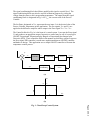
Fig. 5 shows the details of the Block Diagram which can be used to describe the
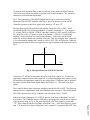
operation of the ON/OFF controller while Fig. 4 shows the hysteresis of the ON/FF
Controller operation as the Error signal varies between –2oF and +2oF.
The operation begins with a check on whether the Controller is ON or OFF. This is
accomplished with VI 2 (AI Sample Channel.vi) and the comparator C1. The output of
C1 is either TRUE or FALSE. If TRUE, then the Controller is OFF, and if FALSE then
the Controller is ON. VI 2 takes its input from Channel 1 of Device 1 (DAQ Board
number). As described earlier, analog input Channel 1 is physically wired to DAC
output Ch. 0 which controls the operation of the fan. Thus by testing the DAC output Ch.
0, we can determine whether the Controller is ON or OFF. This will place the Controller
operating point either on the lower segment or the upper segment of the hysteresis loop in
Fig. 4.
Vco
+5V (ON)
Ve
-2
0V
(OFF)
+2
Fig. 4 The Operation of the ON/OFF Controller
At this time V1, M1 and S1 determine the value of the Error signal (VE). V1 takes the
temperature sample from the analog input Ch. 0 to which the temperature sensor is wired.
M1 multiplies the temperature sample by the scaling factor (TCalibrate) and S1 subtracts
this value from the Front Panel digital control Set Point (VSP) . The result is the Error
signal.
The Controller has to make a decision whether to turn the fan ON or OFF. This decision
making process is implemented with nested Boolean Case structures. The reader should
follow the hysteresis loop in Fig. 4 and the code in Boolean Cases 1, 2 and 3.
Page 4.356.7
If the output from Comparator C1 is TRUE, then the True frame of Boolean Case 1will
be executed. The Controller must be OFF and its operating point is on the lower segment
of the hysteresis loop in Fig. 4. We must check next if the Error signal is greater than
–2oF. This is done inside the True frame of Boolean Case 1. If the Error signal is greater
than –2oF, then the True frame of Boolean Case 2 outputs 0V, keeping the fan OFF. But