1
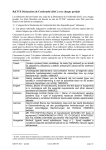
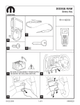
PRO 6000 CPE Quick Installation Guide
Introduction
This Quick Installation Guide covers the basic installation of the PRO 6000 CPE. For more information, refer to the relevant
sections in the Product Manual.
CAUTION
ONLY experienced installation professionals who are familiar with local building and safety codes and,
wherever applicable, are licensed by the appropriate government regulatory authorities should install outdoor
units and antennas.
Failure to do so may void the product warranty and may expose the end user or Service Provider to legal and
financial liabilities. The manufacturer and its resellers or distributors are not liable for injury, damage or
regulation violations associated with the installation of Outdoor Units or antennas.
Français
SEULS les installateurs professionnels expérimentés qui sont familiers avec les codes locaux des bâtiments et
de la sécurité et, lorsque cela s'applique, qui sont autorisés par les autorités gouvernementales de régulation,
doivent installer les unités extérieures et les antennes. Le non-respect de cette clause peut invalider la
garantie du produit et exposer l'utilisateur final ou le prestataire de services à des responsabilités légales et
financières. Le fabricant et ses revendeurs ou distributeurs ne sont pas responsables pour toute blessure,
dommage ou violation de la réglementation associée à l'installation d'unités extérieures ou d'antennes.
Italiano
ATTENZIONE: SOLO professionisti esperti che hanno familiarità con le norme di costruzione locali e coi codici
di sicurezza e, ove applicabile, sono autorizzati dalle autorità governative competenti possono installare unità
esterne ed antenne. Assicurarsi che le unità esterne, antenne e strutture di supporto siano installate
correttamente per eliminare ogni pericolo fisico a persone o cose. In caso contrario, ciò può invalidare la
garanzia del prodotto e può esporre l'utente finale o il fornitore di servizi a responsabilità legali ed economiche.
Anche quando la messa a terra non è obbligatoria in base alla normativa regolatoria applicabile e ai codici
nazionali, è obbligatorio garantire che l'unità esterna e il palo dell'antenna siano messi a terra e idonei
dispositivi di protezione contro i fulmini siano utilizzati in modo da fornire protezione contro le sovratensioni e le
scariche statiche. In ogni caso, il Fornitore e i suoi rivenditori non sono responsabili per eventuali danni fisici,
danni ad oggetti o violazioni del regolamento associati con o causati dall' installazione, la messa a terra o di
protezione contro i fulmini.
Professional Installation Instructions
1 Installation personnel - This product is designed for specific application and must be installed by a qualified person who
2
3
4
5
has RF and related rule knowledge. The general user shall not attempt to install or change the settings.
Installation location - The product shall be installed at a location where the radiating antenna can be kept 60 cm from
nearby person in normal operation condition to meet regulatory RF exposure requirements.
External antenna - Use only the antennas which have been approved by the applicant. The non-approved antenna(s) may
produce unwanted spurious or excessive RF transmitting power which may lead to the violation of FCC/IC limit and is
prohibited.
Installation procedure - Please refer to the user’s manual for the details.
Warning - Please carefully select the installation position and make sure that the final output power does not exceed the
limit set force in relevant rules. The violation of the rule could lead to serious federal penalty.
Instructions d'installation professionnelle
1 Installation - Ce produit est destine a un usage specifique et doit etre installe par un personnel qualifie maitrisant les
2
3
4
5
radiofrequences et les regles s'y rapportant. L'installation et les reglages ne doivent pas etre modifies par l'utilisateur final.
Emplacement d'installation - En usage normal, afin de respecter les exigences reglementaires concernant l'exposition
aux radiofrequences, ce produit doit etre installe de facon a respecter une distance de 60cm entre l'antenne emettrice et
les personnes.
Antenn externe - Utiliser uniiquement les antennes approuvees par le fabricant. L'utilisation d'autres antennes peut
conduire a un niveau de rayonnement essentiel ou non essentiel depassant les niveaux limites definis par FCC/IC, ce qui
est interdit.
Procedure d'installation - Consulter lemanuel d'utilisation.
Avertissement - Choisir avec soin la position d'installation et s'assurer que la puissance de sortie ne depasse pas les
limites en vigueur. La violation de cette regle peut conduire a de serieuses penalites federales.
P/N 216000
-1-
May 2012
PRO 6000 CPE Quick Installation Guide
Overview
The PRO 6000 CPE is a WiMAX subscriber station designed to provide Internet access for a home or small office. The PRO CPE
includes an outdoor unit (ODU) connected to an indoor unit (IDU). The ODU provides the WiMAX Internet link, and the IDU
serves as the gateway for a local Ethernet wired and phone.
The indoor unit includes:
•
•
•
One standard RJ-45 Ethernet port for LAN connections,
One 8 PIN RJ-45 Ethernet port for connection to the ODU. This cable provides a dedicated Power-over-Ethernet (PoE) power
supply to the ODU, as well as a data link between the ODU and the IDU. The IDU should be connected to an AC power
connection.
One RJ-11 port for telephone (VoIP) connection
The PRO CPE provides a web-based management interface for the configuration of all features.
Package Content
Please make sure that each package contains the items listed below:
•
•
•
•
•
•
Outdoor WiMAX unit (ODU)
Indoor Power Supply unit (IDU) with adaptor plug
Crossed Ethernet cable with two RJ-45 connectors for connecting the IDU to a PC/HUB/switch.
Pole mounting kit
Optional - Tilt Accessory kit (ordered separately)
This Quick Installation Guide
IDU
ODU
Figure 1: ODU and IDU
Additional Installation Requirements
• Indoor-to-outdoor Category 5E PoE 4x2x24# FTP Ethernet cable with two shielded RJ-45 connectors*
•
•
•
•
and an RJ-45
connectors crimping tool.
Grounding cable with an appropriate termination.
Sealing materials: mastic tape (Scotchfil™ Electrical Insulation Putty), Cold Shrink sealing kit.
Installation tools and materials
Sealing gland fastening tool*
INFORMATION
Items marked with an asterisk (*) are available from the manufacturer.
Installing the ODU
Before installing the CPE, verify that you have all the items listed in the package checklist. If any of the items are missing or
damaged, contact your WiMAX service provider.
Selecting a Location
The ODU should be pole-mounted outdoors and aligned so its antenna faces the nearest WiMAX base station. When selecting a
suitable location for the unit, consider these guidelines:
•
•
•
•
Place the ODU as high as possible to achieve the best possible link quality.
Place the ODU away from power and telephone lines.
Avoid placing the ODU too close to any metallic reflective surfaces.
Be sure to ground the ODU with an appropriate grounding wire (not included) by attaching it to the grounding screw on the
unit and to a good ground connection.
P/N 216000
-2-
May 2012
PRO 6000 CPE Quick Installation Guide
Mounting the ODU
Mount the ODU unit on a 1"-4" pole using the supplied kit (Figure 2), or the optional Tilt accessory.
Using the Clamp
1
2
3
4
Thread the M10*100mm bolt through a spring washer, flat washer and the bracket holes.
With the connector facing downward, attach the ODU to a 1" -4" pole.
Attach the bracket to the other side of the pole.
Thread the M10*100 mm bolts through both holes on either side. Tighten the nuts.
Pole-Mount Bracket
Attaches to a 1~4 inch
diameter pole
Weather Proof Sealing
Glands
M10*100 Bolt, nuts and
spring washers
Protect the RJ-45 Ethernet Port
Figure 2: Mounting the ODU on the Pole
Using the Tilt Accessory
1
2
3
Attach the Tilt accessory to the ODU using the two pairs of flat washers, spring washers and nuts supplied in the Tilt kit.
Mount the Tilt accessory on a 1" to 4" pole using two 9/16" metal bands.
Slightly release the Tilt Control Screw, tilt the ODU downward/upward as required, and re-tighten the screw.
Tilt Accessory
Tilt Control Screw
Figure 3: ODU Pole Installation Using the Tilt Accessory, Vertical Polarization
P/N 216000
-3-
May 2012
PRO 6000 CPE Quick Installation Guide
Installing The IDU
The IDU can only be mounted indoors. It should be mounted on any horizontal surface, such as a desktop or shelf. Be sure to
select a suitable location for the device within 100 m (328 ft.) of the ODU. Consider these guidelines:
•
•
•
•
Select a cool, dry place, which is out of direct sunlight.
The device must be near an AC power outlet that provides 100 to 240 V, 50 to 60 Hz with proper grounding.
The device should be accessible for network cabling.
The overall length of the Ethernet cables from the ODU to the IDU and from the IDU to the PC must not exceed 100m.
You must plan a cable route from the ODU to the IDU indoors. Consider these guidelines:
•
•
•
Determine a building entry point for the cable.
Determine if conduits, bracing, or other structures are required for safety or protection of the cable.
For additional lightning protection, it is recommended to use a lightning arrestor immediately before the Ethernet cable enters
the building.
Connecting the Cables
CAUTION
Use ONLY the power adapter supplied with the IDU. Otherwise, the product may be damaged.
Input/Output serial
console (debug or
distribution automation
PoE
LEDs
ODU
Grounding
CAT 5 Ethernet cable
IDU
Figure 4: CPE Connections
Outdoor Connections
Connecting the Grounding Cable
Connect a grounding cable between the Ground terminal of the ODU (marked
) and a good ground connection.
Preparing and Connecting the IDU-ODU Cable
Use only Category 5E 4x2x24# FTP outdoor cables from an approved manufacturer. The cable provides pin-to-pin connection on
both ends.
P/N 216000
-4-
May 2012
PRO 6000 CPE Quick Installation Guide
1
Prepare the cable: Use a crimp tool for RJ-45 connectors to prepare the wires. Insert them into the appropriate pins and use
the tool to crimp the connector. Make sure to do the following:
»
Remove as small a length as possible of the external jacket. Verify that the external jacket is well inside the sealing cover
when connected to the unit, to ensure good sealing.
»
Pull back the shield drain wire before inserting the cable into the RJ-45 connector, to ensure a good connection with the
connector's shield after crimping.
The following figure shows the required wire pair connections. The color codes used in standard cables supplied by the
manufacturer are as listed in the table:
Wire color
Pin
Blue
1
Blue/white
2
Orange
3
Orange/white
6
Brown
4
Brown/white
5
Green
7
Green/white
8
Figure 5: Ethernet Connector Pin Assignments
2
Connect the cable (see Figure 6):
Remove the sealing gland plug from the gland nut.
a
b
Open the sealing gland nut and remove it. Do not disassemble the gland base from the bracket.
c
Insert the cable into the sealing gland base and connect it to the RJ-45 connector at the bottom of the CPE, labeled
. Make sure that the connector is completely inserted and tightened.
d
Insert the rubber bushing on the cable into the gland base.
Sealing Gland base
Rubber Bushing
Sealing Gland Nut
Figure 6: Inserting the Cable into the Sealing Cap
e
Tighten the gland nut. Use the dedicated tool for fastening the sealing glands.
Figure 7: Sealing Gland Fastening Tool
P/N 216000
-5-
May 2012
PRO 6000 CPE Quick Installation Guide
3
Seal the connector:
a Attach the mastic tape (Scotchfil™ Electrical Insulation Putty) and wrap it around the connector butting up against the
connector. Do not over stretch.
b
Squeeze to tighten the mastic sealer. Make sure there are no air bubbles.
c
Slide the cold shrink sleeve on top of the connector. Make sure that the sleeve covers both cable connector and unit
connector.
Cold Shrink Sleeve
Cold Shrink Seal
Cord
Figure 8: Cold Shrink Tubing
d
Pull the cord slowly to shrink the sleeve.
Indoor Connections
1
Assemble an RJ-45 connector with a protective cover on the other end of the IDU-ODU cable. Refer to the pin assignment
and color codes in standard cables described above.
2
Connect the other end of the IDU-ODU cable to the single connector on the IDU, labeled “TO/FROM ODU PoE (RJ45)” (see
Figure 4).
3
4
Connect one end of the supplied Ethernet cable to a PC/Hub/Switch.
Connect the other end of the Ethernet cable to the IDU port, labeled with a computer illustration (see Figure 4).
CAUTION
5
6
Do not connect the data equipment to the PoE port on the IDU, as it supplies DC power to the ODU, and this
may harm other equipment connected to it.
Use a telephone cable to connect a phone to the connector labeled with a telephone illustration (see Figure 4)
Connect the indoor unit to the AC mains using the power adapter supplied with the unit.
Checking for Proper Operation
1
2
Verify data connectivity by sending a ping command to the BTS or by connecting to the Internet.
Check the LED functionality according to the following table:
Description
Color
Functionality
Fault + Ethernet indication LED
Red
•
•
•
•
•
WiMAX W/L link availability LED
P/N 216000
Green
•
•
•
•
Lights at start up
During the built-in test (BIT) blinks (300ms on, 300ms off)
Off/On - If BIT completed successfully. If BIT failed, it continues
lightning
On - If fatal error/critical alarm appears during run time
Blinking - If PoE Ethernet is connected and no errors found (1sec
on, 3sec off).
Lights at start up
Off - upon BIT completion
Blinking - the CPE is synchronized with the BS and 5> SNR ≥ 3dB.
On - when the CPE is synchronized with the BS and the SNR
-6-
≥ 5dB
May 2012
PRO 6000 CPE Quick Installation Guide
Description
Color
Functionality
3 x WiMAX link signal strength LEDs
Green
•
•
Lights at start up.
Off - upon BIT completion
Signal strength display:
•
•
•
•
•
•
LED1 blinks when 12>SNR≥8dB
LED1 lights when SNR≥12dB
LED2 blinks when 18>SNR≥15dB
LED 2 lights when SNR≥18dB
LED3 (right side) blinks when 25>SNR≥20dB
LED3 (right side) lights when SNR>=25dB
WiMAX W/L link
availability (green)
Fault + Eth indication (red)
3 x WiMAX link signal
strength (green)
Figure 9: ODU LEDs
Commissioning
1
2
3
4
5
The PC receives an IP by DHCP, as DHCP server is enabled by default. Alternatively you can manually set the PC's IP
settings to 192.168.254.250, then follow the instructions below to access the web interface and start the Setup Wizard.
From a connected PC, use a web browser to access the CPE’s web interface. The web interface allows you to configure
WiMAX settings.
Open your web browser and type the IP address 192.168.254.251
Type the default username/password: admin/admin and click LOGIN .
Configure the basic parameters required for connectivity with the BTS. The following table includes the basic parameters and
their default values.
Basic Parameters
Table 1: Basic Parameters
Item
Default Value
Comment
User Name (WiMAX)
WAN mac address and WiMax.com
realm, e.g:
[email protected]
Should be supplied by system
administrator. Configured in the
Advanced> Authentication window
WiMAX Password
quickynikynyoky
Domain
(also Eng > WiMAX Config > Realm)
Frequency
Full Scan
Should be supplied by system
administrator.
Telephony - SIP Server, phone number,
authentication, enable the phone
Disabled
Optional
VoIP is disabled by default and should
be enabled by the operator
Federal Communication Commission Interference Statement
This equipment has been tested and found to comply with RSS-192 and 197 of the Industry Canada Rules. This equipment also
complies with the limits for a class B digital device, pursuant to ETSI EN 301 489-1 and Part 15 of the FCC Rules. These limits
are designed to provide reasonable protection against harmful interference in a residential installation. This equipment
generates, uses and can radiate radio frequency energy and, if not installed and used in accordance with the instructions, may
cause harmful interference to radio communications. However, there is no guarantee that interference will not occur in a
P/N 216000
-7-
May 2012
PRO 6000 CPE Quick Installation Guide
particular installation. If this equipment does cause harmful interference to radio or television reception, which can be determined
by turning the equipment off and on, the user is encouraged to try to correct the interference by one of the following measures:
•
•
•
•
Reorient or relocate the receiving antenna.
Increase the separation between the equipment and receiver.
Connect the equipment into an outlet on a circuit different from that to which the receiver is connected.
Consult the dealer or an experienced radio/TV technician for help.
This device complies with Part 15 of the FCC Rules. Operation is subject to the following two conditions:
(1) This device may not cause harmful interference, and
(2) this device must accept any interference received, including interference that may cause undesired operation.
FCC Radiation Exposure Statement
This equipment complies with FCC radiation exposure limits set forth for an uncontrolled environment. This equipment should be
installed and operated with minimum distance 20cm between the radiator and your body.
This transmitter must not be co-located or operating in conjunction with any other antenna or transmitter.
Europe - EU Declaration of Conformity
This device complies with the essential requirements of the R&TTE Directive 1999/5/EC. The following test methods have been
applied in order to prove presumption of conformity with the essential requirements of the R&TTE Directive 1999/5/EC:
•
•
•
•
•
•
EN 60950-1:2006 + A11:2009 + A1:2010 + A12: 2011
EN 302 326-2 V1.2.2: 2007
EN 302 326-3 V1.3.1 : 2008
EN50385 : 2002
EN 301 489-1 V1.8.1 (2008-04)
EN 301 489-4 V1.4.1: 2009
Industry Canada statement
This device complies with RSS-192 & RSS-197 of the Industry Canada Rules. Operation is subject to the following two
conditions:
1) This device may not cause harmful interference, and
2) this device must accept any interference received, including interference that may cause undesired operation.
Ce dispositif est conforme à la norme CNR-192 & CNR-197 d'Industrie Canada applicable aux appareils radio exempts de
licence. Son fonctionnement est sujet aux deux conditions suivantes: (1) le dispositif ne doit pas produire de brouillage
préjudiciable, et (2) ce dispositif doit accepter tout brouillage reçu, y compris un brouillage susceptible de provoquer un
fonctionnement indésirable.
NOTE!
Radiation Exposure Statement:
This equipment complies with Canada radiation exposure limits set forth for an uncontrolled environment. This
equipment should be installed and operated with minimum distance 60 cm between the radiator & your body.
Français
Pour l'utilisation de dispositifs mobiles
Déclaration d'exposition aux radiations:
Cet équipement est conforme aux limites d'exposition aux rayonnements IC établies pour un environnement
non contrôlé. Cet équipement doit être installé et utilisé avec un minimum de 60 cm de distance entre la
source de rayonnement et votre corps.
CAUTION
P/N 216000
Any changes or modifications not expressly approved by the party responsible for compliance could void the
user's authority to operate this equipment
-8-
May 2012
PRO 6000 CPE Quick Installation Guide
Česky [Czech]
Dansk
[Danish]
Deutsch
[German]
Eesti
[Estonian]
English
Español
[Spanish]
Ελληνική
[Greek]
Français
[French]
Italiano
[Italian]
Latviski
[Latvian]
Lietuvių
[Lithuanian]
Nederlands
[Dutch]
Malti
[Maltese]
Magyar
[Hungarian]
Polski
[Polish]
Português
[Portuguese]
Slovensko
[Slovenian]
Slovensky
[Slovak]
Suomi
[Finnish]
Svenska
[Swedish]
P/N 216000
[Jméno výrobce] tímto prohlašuje, že tento [typ zařízení] je ve shodě se základními
požadavky a dalšími příslušnými ustanoveními směrnice 1999/5/ES.
Undertegnede [fabrikantens navn] erklærer herved, at følgende udstyr [udstyrets
typebetegnelse] overholder de væsentlige krav og øvrige relevante krav i direktiv
1999/5/EF.
Hiermit erklärt [Name des Herstellers], dass sich das Gerät [Gerätetyp] in
Übereinstimmung mit den grundlegenden Anforderungen und den übrigen
einschlägigen Bestimmungen der Richtlinie 1999/5/EG befindet.
Käesolevaga kinnitab [tootja nimi = name of manufacturer] seadme [seadme tüüp =
type of equipment] vastavust direktiivi 1999/5/EÜ põhinõuetele ja nimetatud direktiivist
tulenevatele teistele asjakohastele sätetele.
Hereby, [name of manufacturer], declares that this [type of equipment] is in compliance
with the essential requirements and other relevant provisions of Directive 1999/5/EC.
Por medio de la presente [nombre del fabricante] declara que el [clase de equipo]
cumple con los requisitos esenciales y cualesquiera otras disposiciones aplicables o
exigibles de la Directiva 1999/5/CE.
ΜΕ ΤΗΝ ΠΑΡΟΥΣΑ [name of manufacturer] ∆ΗΛΩΝΕΙ ΟΤΙ [type of equipment]
ΣΥΜΜΟΡΦΩΝΕΤΑΙ ΠΡΟΣ ΤΙΣ ΟΥΣΙΩ∆ΕΙΣ ΑΠΑΙΤΗΣΕΙΣ ΚΑΙ ΤΙΣ ΛΟΙΠΕΣ ΣΧΕΤΙΚΕΣ
∆ΙΑΤΑΞΕΙΣ ΤΗΣ Ο∆ΗΓΙΑΣ 1999/5/ΕΚ.
Par la présente [nom du fabricant] déclare que l'appareil [type d'appareil] est conforme
aux exigences essentielles et aux autres dispositions pertinentes de la directive 1999/
5/CE.
Con la presente [nome del costruttore] dichiara che questo [tipo di apparecchio] è
conforme ai requisiti essenziali ed alle altre disposizioni pertinenti stabilite dalla
direttiva 1999/5/CE.
Ar šo [name of manufacturer / izgatavotāja nosaukums] deklarē, ka [type of equipment
/ iekārtas tips] atbilst Direktīvas 1999/5/EK būtiskajām prasībām un citiem ar to
saistītajiem noteikumiem.
Šiuo [manufacturer name] deklaruoja, kad šis [equipment type] atitinka esminius
reikalavimus ir kitas 1999/5/EB Direktyvos nuostatas.
Hierbij verklaart [naam van de fabrikant] dat het toestel [type van toestel] in
overeenstemming is met de essentiële eisen en de andere relevante bepalingen van
richtlijn 1999/5/EG.
Hawnhekk, [isem tal-manifattur], jiddikjara li dan [il-mudel tal-prodott] jikkonforma malħtiġijiet essenzjali u ma provvedimenti oħrajn relevanti li hemm fid-Dirrettiva 1999/5/
EC.
Alulírott, [gyártó neve] nyilatkozom, hogy a [... típus] megfelel a vonatkozó alapvetõ
követelményeknek és az 1999/5/EC irányelv egyéb elõírásainak.
Niniejszym [nazwa producenta] oświadcza, że [nazwa wyrobu] jest zgodny z
zasadniczymi wymogami oraz pozostałymi stosownymi postanowieniami Dyrektywy
1999/5/EC.
[Nome do fabricante] declara que este [tipo de equipamento] está conforme com os
requisitos essenciais e outras disposições da Directiva 1999/5/CE.
[Ime proizvajalca] izjavlja, da je ta [tip opreme] v skladu z bistvenimi zahtevami in
ostalimi relevantnimi določili direktive 1999/5/ES.
[Meno výrobcu] týmto vyhlasuje, že [typ zariadenia] spĺňa základné požiadavky a
všetky príslušné ustanovenia Smernice 1999/5/ES.
[Valmistaja = manufacturer] vakuuttaa täten että [type of equipment = laitteen
tyyppimerkintä] tyyppinen laite on direktiivin 1999/5/EY oleellisten vaatimusten ja sitä
koskevien direktiivin muiden ehtojen mukainen.
Härmed intygar [företag] att denna [utrustningstyp] står I överensstämmelse med de
väsentliga egenskapskrav och övriga relevanta bestämmelser som framgår av direktiv
1999/5/EG.
-9-
May 2012