1
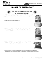
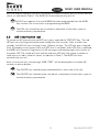
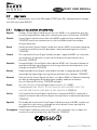
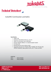
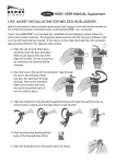
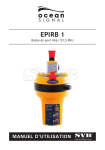
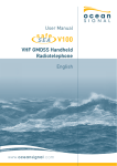
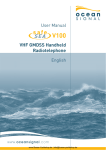
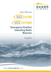
User Manual
MOB1
Personal Locator Device
(Incorporating AIS and DSC)
English
© 2014 Ocean Signal Ltd
The technical data, information and illustrations contained in this manual were believed to
be correct at the time of print. Ocean Signal Ltd reserve the right to change specifications
and other information contained in this manual as part of our continual improvement
process.
No part of this manual may be reproduced, stored in a retrieval system or transmitted in
any form, electronic or otherwise, without the prior and express written permission of
Ocean Signal Ltd.
No liability can be accepted for any inaccuracies or omissions in this manual.
Ocean Signal® and rescueME® are registered trademarks of Ocean Signal Ltd.
MOB1 USER MANUAL
IN CASE OF EMERGENCY
Use only in situations of grave
or imminent danger
If the MOB1 is correctly fitted to the life jacket, then the MOB1 will automatically
activate when the life jacket inflates. This guide shows how to manually activate
the MOB1.
•
Slide the red Arming Tab down (1)
•
Slide the grey Activation Slide (2) sideways by pulling on the
attached tape and remove. This will release the antenna and
activate the MOB1
1
2
•
If the strobe light does not start flashing, manually switch the
MOB1 on by pressing the ON Key (3)
•
Always turn off the MOB1 immediately after you have been rescued to avoid
interference with other users. Refer to section 5.4 for deactivation instructions.
3
3
Version 01.01 17/06/2015
MOB1 USER MANUAL
CONTENTS
IN CASE OF EMERGENCY ........................................................................................................................... 3
1.
GENERAL............................................................................................................................................ 5
1.1
Introduction ................................................................................................................................. 5
1.2
Exposure to RF Electromagnetic Energy .................................................................................... 5
1.3
Warnings...................................................................................................................................... 5
2.
MOB1 OVERVIEW ................................................................................................................................ 6
3.
LIFE JACKET INSTALLATION............................................................................................................. 7
4.
MMSI configuration ............................................................................................................................ 9
5.
6.
7.
4.1
Self Identification ........................................................................................................................ 9
4.2
User MMSI ................................................................................................................................... 9
OPERATION .......................................................................................................................................11
5.1
Automatic Activation ..................................................................................................................11
5.2
Manual Activation .......................................................................................................................11
5.3
DSC All Ship Distress Alert transmission..................................................................................12
5.4
Deactivation ................................................................................................................................12
5.5
Rewinding the antenna...............................................................................................................12
Testing ...............................................................................................................................................13
6.1
Functional test............................................................................................................................13
6.2
DSC Transmission Test ..............................................................................................................13
6.3
AIS transmission test .................................................................................................................14
Appendix ............................................................................................................................................15
7.1
Maintenance and Troubleshooting ............................................................................................15
7.2
Batteries .....................................................................................................................................15
7.3
Transport ....................................................................................................................................15
7.4
Disposal ......................................................................................................................................15
7.5
Specifications .............................................................................................................................16
7.6
Country of Intended Use.............................................................................................................16
7.7
Approvals ....................................................................................................................................17
7.8
Limited Warranty........................................................................................................................18
4
Part No 912S-01517
MOB1 USER MANUAL
1.
GENERAL
1.1
Introduction
The rescueME range of products provides the user with the latest technology specifically
designed for compact size and ease of operation. The MOB1 is intended to alert your
vessel in the event that you fall overboard. It will then plot your location on a suitable AIS
equipped chart plotter.
1.2
Exposure to RF Electromagnetic Energy
This product also complies with EN62479 (EU) and RSS-102 (Canada).
This product has been evaluated for compliance with the FCC RF exposure limits given in
CFR 47 part 1.307(b) at a distance of greater than 5cms.
1.3
Warnings
A Man Over Board AIS transmitter is only intended for short range signalling to
an AIS receiver installed onboard your own vessel. It will not directly alert the
emergency services or any other vessels.
This equipment is intended for emergency use only and it should not be used for
routine tracking of persons or property, including routine tracking of divers.
If self-test is performed more frequently than once a month, then battery life
may be reduced.
This radio device is designed to only provide an effective alerting and locating
capability in close proximity to a vessel. This radio beacon is NOT an EPIRB.
DSC functionality may vary or be disabled according to individual countries
regulations. Older DSC radios may not respond to the individual relay call.
Interface diagram showing typical usage
5
Version 01.01 17/06/2015
MOB1 USER MANUAL
2.
MOB1 OVERVIEW
1)
Antenna behind activation slide
2)
Activation Slide
3)
Arming Slide (shown in safe position)
4)
ON Key (for manual activation)
5)
Strobe and Indicator LED
6)
TEST/OFF Key
7)
Arming Slide (in armed position)
8)
Activation Tape
9)
Mounting Bracket
1
2
3
10) Antenna Rewind Tool
11) Programming Adaptor
4
5
6
7
MOB1 Controls shown
in activated condition
8
9
10
6
11
Part No 912S-01517
MOB1 USER MANUAL
3.
LIFE JACKET INSTALLATION
If your rescueME MOB1 is not already pre-installed into the lifejacket, please follow the
instructions below carefully. The diagrams below assume that the life jacket inflation tube
is on the left hand side (as viewed). If the tube is on the right hand side then the tape
should be fitted on the opposite sides shown
•
Slide the red arming tab down.
Carefully move the grey slide to just
expose the slot. Do not move it too
far otherwise the antenna will be
released.
• Pass the loop of the strap
through the slot in the
activation clip and pass the
tape back through the loop.
Return the activation slide to
the centre and move the red
arming tab back to lock the
slide in place.
•
Take the bracket and pass the tape through the slots as shown below, making sure
that tape does not get twisted.
•
On completion, the tape should now be
connected to the bracket and MOB1 as
shown.
7
Version 01.01 17/06/2015
MOB1 USER MANUAL
•
Pass the tape around the bladder of the life jacket and clip the
bracket to the MOB1 so that the MOB1 will be on the outside
of the inflation tube as shown.
•
Pull the tape tight with the free end of the tape, so that
the bladder is free to inflate and remains folded in
accordance with the life jacket manufacturer’s
instructions. Do not over tighten the tape.
Test for tightness by ensuring you can freely insert a
finger in between the tape and the bladder.
•
Once the MOB1 is fully attached to the life-jacket, you are
ready to arm the device, by sliding the red arming tab down.
Failure to arm the MOB1 will inhibit the auto
activation of the MOB1 when needed and will STOP
the life jacket inflating correctly.
If the MOB1 has turned on during the installation
process, make sure it is turned off by pressing and
holding the TEST/OFF Key until the LED flashes red
twice and release.
•
Repack the bladder into the cover, ensuring the bladder does not get trapped in the
fastening mechanism or tangled up.
For installation to life jackets where the bladder is permanently attached to the
cover, please see the separate instruction sheet, available from the Ocean
Signal website.
8
Part No 912S-01517
MOB1 USER MANUAL
4.
MMSI configuration
If your vessel has a DSC enabled VHF radiotelephone, it is strongly recommended to
programme your vessels MMSI number into your MOB1. This will allow the MOB1 to send
the details of the man over board incident direct to the radio and sound the alarm.
4.1
Self Identification
The MOB1 is supplied with the self identification number pre programmed. This number is
specific to each MOB1 and cannot be changed. The MMSI displayed on the DSC receiver
will always start with ‘972’ irrespective of the country it was purchased in.
4.2
User MMSI
(Applies to DSC enabled units only)
To be able to send DSC messages to your vessel, the MMSI number of the vessel needs to
be programmed into the MOB1. This is achieved using a PC based application and its
display screen.
4.2.1
Installation
The programming software for configuring the User MMSI into the MOB1 can be
downloaded from www.oceansignal.com/installers. The version downloaded will only allow
the DSC options available in your country. Some functions described below may not be
available to you.
Save the file to your computer and open it to run the installer. Follow the instructions on
screen.
4.2.2
Configuration
Run the application from the desktop icon. The screen
shown here will appear.
Enter the nine digit MMSI of the vessel in the box provided
and select update beacon.
(In the USA, after the MMSI has been entered, a second box for a
group MMSI will appear. Enter your group MMSI here if applicable,
noting that group MMSI numbers should always start with a zero.)
On completion press the Update Device button to proceed.
A new screen with further instructions will appear.
Slide the Arming Slide down to the armed position and fit
the black rubber Programming Adaptor so that the Push
Button is over the TEST/OFF Key and the aperture is over
the clear indicator window.
To put the MOB1 into programming mode, press the
9
Version 01.01 17/06/2015
MOB1 USER MANUAL
TEST/OFF Key for at least fifteen seconds. The LED will start flashing green. Release the
key. When ready press the Yes Key on screen.
The display will now change to the programming
mode. Place the MOB1 over the screen so that the
clear STROBE indicator window is over the white
box. Press the <F10> Key on your keyboard to
commence programming.
When the programming is complete, the screen will
change. Remove the MOB1 and check that the LED
starts flashing green. Turn the MOB1 off by pressing
the TEST/OFF Key for one second. The LED will
blink red twice. Press the <F12> Key to exit the
programming mode.
If the programming fails, the LED will start flashing
Red after a short period of time. Turn the unit off by pressing the TEST/OFF Key and retry.
When programming is completed, return the arming tab to the locked position. Your MOB1
is now ready for fitting to the life jacket (Section 3) for use.
Note: Make sure the display screen is set to full brightness before commencing
programming the MOB1.
10
Part No 912S-01517
MOB1 USER MANUAL
5.
OPERATION
WARNING: Use only in situations of grave and imminent danger.
Misuse may result in a severe penalty.
Ensure that your MOB1 is always fitted with an unused battery that is within the marked
expiry date. Failure to do so may result in reduced operating time when used in a real
emergency. Please observe the recommendations on testing in section 6.
5.1
Automatic Activation
When correctly packed in a lifejacket the MOB1 will automatically activate when the
lifejacket inflates. Should the lifejacket fail to fully inflate, it may be necessary to assist
the Activation Slide by pulling on the Activation Tape to fully release the Activation Slide.
5.2
Manual Activation
Only activate your MOB1 in situations requiring assistance ONLY in an
emergency. Deliberate misuse of your MOB1 may result in a fine.
•
To manually activate your MOB1 in an emergency, slide the red Arming Slide down.
Slide the grey Activation Slide to the Left or Right. The strobe light will start flashing.
The MOB1 will automatically start transmitting after 15seconds.
•
If the MOB1 fails to activate when the slide is removed, press the ON Key down until
the green LED starts flashing. Release the key.
•
The antenna will be automatically released. Keep the MOB1 well away from your
eyes when activating.
•
Upon activation, the indicator LED will show eight short flashes during AIS
transmission and one long flash during DSC transmission. The colour of the flash
will be Red during position acquisition and green when the GPS position is being
received.
•
•
When operating the MOB1, tether the beacon to your body or the life jacket.
Hold your beacon with the antenna standing vertically. Keep the area marked ‘GPS
Antenna’ free from obstruction, which would interfere with the GPS reception.
Covering this area will interfere with the GPS reception.
11
Version 01.01 17/06/2015
MOB1 USER MANUAL
5.3
DSC All Ship Distress Alert transmission
Applies only in countries where DSC All Ships Alerts are allowed.
Press and hold the ON Key for over 5 seconds to transmit a single DSC All Ships Distress
Alert. This should only be done in a dire emergency, if it is obvious that your alert is not
being acted upon by you own vessel. After the key is pressed, the Green LED will start
flashing then become steady. Release the key to commence transmission of a single DSC
transmission. The LED will blink rapidly to indicate a DSC Distress is being transmitted to
ALL SHIPS; red if there is no position available and green when GPS position is being
received.
5.4
Deactivation
To deactivate your MOB1 after use or if it is accidentally activated, press the TEST/OFF Key
until the LED flashes red twice, then release.
5.5
Rewinding the antenna
To rewind the antenna after activation or transmission testing,
use the small grey Antenna Rewind tool supplied in the box.
Place the moulded cap of the antenna into the space (1) and pass
the tool through the round hole in the top of the MOB1 and place
over the antenna spring just behind the cap (2). Rotate the tool
anti-clockwise until the antenna is fully wound up (3). Whilst
holding the antenna in place with the tool, replace the activation
slide and remove the tool (4).
2
3
4
1
5
If the MOB1 has activated, turn it off by pressing the TEST/OFF
Key until the LED flashes twice (5).
Rotating the antenna rewind tool in the clockwise direction may result in
damage to the antenna
12
Part No 912S-01517
MOB1 USER MANUAL
6.
Testing
Routine testing of your MOB1 once a month is recommended to ensure it is in good
working order if needed, but please follow the guidance notes below on the frequency that
tests should be carried out. Please remember that each test will reduce the battery
capacity slightly and reduce the operation time of your MOB1 during an emergency.
6.1
Functional test
To test your MOB1 is functioning correctly, press and hold the TEST/OFF Key for one
second. The red LED will start flashing, indicating test mode is activated. The switch may
now be released. After a short pause the strobe will flash and then the unit will
automatically turn off and the indicator LED will flash green or amber to show a pass or
red to show fail status.
The number of flashes in each group indicates the battery status or failure as shown in
Table 1. This battery indicator is used as the electronic witness that the MOB1 has been
activated.
Green / Amber Indicator.
Changes to Amber after 1 hour of use
Red indicator
status
No of Flashes
Type of Failure
1 Flash
No of Hours Used
0 to 1hr (Green)
1 to 2hrs (Amber)
2 Flashes
2 to 4hrs (Amber)
Frequency generation
3 Flashes
4 to 6hrs (Amber)
Transmit Power
4 Flashes
6 to 8hrs (Amber)
Battery failed
5 Flashes
8 to 10hrs (Amber)
No GPS Fix
6 Flashes
Over 10hrs (Amber)
Table 1: Pass/Fail indication
The amber test result indicates the battery has been used for over one hour or
the allowed number of tests has been exceeded. The MOB1 will still operate
normally in distress, but the battery should be replaced immediately to ensure
the full operating life when your MOB1 is needed.
The Pass/Fail status indication is repeated a second time after a short delay.
6.2
DSC Transmission Test
To initiate a DSC test transmission, press and hold the TEST/OFF Key. The red LED will
start flashing, then after five seconds become steady. Release the TEST/OFF Key. After a
short pause a DSC Routine call to your vessel’s DSC VHF will be transmitted. The strobe
13
Version 01.01 17/06/2015
MOB1 USER MANUAL
will flash and the indicator LED will flash green or amber to show a pass or red to show fail
status, as indicated in Table 1. The MOB1 will then automatically turn off.
The DSC test requires that a valid MMSI has been programmed into the MOB1.
See section 4 for instructions on programming the MMSI.
The DSC test should only be carried out a maximum of two times a year to
minimise battery consumption.
6.3
AIS transmission test
To initiate an AIS transmission and GPS test, press and hold the TEST/OFF Key. The red
LED will start flashing and then become steady after five seconds. After a further five
seconds, the LED will start flashing slowly. Release the key. The LED will give a long red
flash followed by a short green flash until GPS lock is achieved. After GPS lock is obtained,
the MOB1 will transmit a single burst of AIS messages indicated by eight short flashes of
the green LED. The strobe will flash and the indicator LED will flash green or amber to
show a pass or red to show fail status, as indicate in Table 1. The MOB1 will then
automatically turn off.
After a successful test, the message “MOB1 TEST” will be displayed on a suitable AIS
receiver or plotter display.
The AIS/GPS test should only be attempted with a clear view of the sky.
The AIS/GPS test should only be carried out a maximum of three times a year to
minimise battery consumption.
14
Part No 912S-01517
MOB1 USER MANUAL
7.
Appendix
7.1
Maintenance and Troubleshooting
Your MOB1 will require little maintenance except periodic cleaning, if required. Always
use a damp cloth to clean the case and dry thoroughly. Do not use solvents or other
cleaning fluids as this may cause the plastics to deteriorate. Ensure the antenna is free to
unwind.
7.2
Batteries
The MOB1 contains Lithium metal batteries for long operating life. Your battery must be
replaced either prior to the expiry date or after the MOB1 has been used, even if only
activated for a short period of time. Battery replacement must be carried out at an Ocean
Signal authorised battery replacement centre.
7.3
Transport
When shipping your MOB1 the following guidance and regulations should be followed, but
you are advised to contact your nearest battery replacement centre or Ocean Signal prior
to shipping as regulations may have changed.
•
Always pack your MOB1 securely in a stout cardboard carton. Ocean Signal advises
that you keep the original packaging in case of return for service.
•
For surface transport the MOB1 may be shipped under special provision 188.
•
For air transport the MOB1 should be shipped as category UN3091 and packed under
IATA packing instruction 970 section II. If you are hand carrying your MOB1 on an
aircraft please contact you airline for advice.
•
Consult the manufacturer’s instructions for information on carrying a life jacket in
your luggage on board aircraft.
7.4
Disposal
Care should be taken when disposing of your MOB1 when it is no longer required. It is
recommended to remove the battery from the MOB1 by removing the case lid. The case
screws are covered by the top label. Dispose of the battery in accordance with local waste
regulations. Please note that the MOB1 is not user serviceable and opening the case
will invalidate the warranty.
15
Version 01.01 17/06/2015
MOB1 USER MANUAL
7.5
Specifications
AIS transmission
Transmit Power (EIRP) ..............................................................................................................1Watt
Frequency ............................................................................................ 161.975/162.025MHz ±500Hz
Baud rate ............................................................................................................................ 9600baud
Synchronisation ........................................................................................................................... UTC
Messages ............................................................... Message 1 (Position), Message 14 (MOB status)
Repetition interval .............................................................................................. 8 messages/minute
............................................................................................ Message 14 sent twice every 4 minutes
DSC Transmission1
Transmit Power (EIRP) .......................................................................................................... 0.5Watt
Frequency ...................................................................................................................... 156.525MHz
Messages ................................................................................................ Individual Distress Relay*
.................................................................................................................. All Ships Distress Alert*1
Message repetition ...................................................................... Once every 5 minutes (Relay only)
Baud rate ............................................................................................................................ 1200baud
*Single call made on press of the activation button, in regions where it is allowed.
Environmental
Temperature range (operational) ......................................................................... -20°C - +55°C
Temperature range (storage) ............................................................................... -30°C -+70°C
Damp Heat (humidity) ............................................................................................. 40°C at 93%
Drop (hard surface) ................................................................................................. 1m : 6 sides]
Designed to meet Drop (water)............................................................................... 20m : 3sides
Water immersion .......................................................................................... 2 bar : >60minutes
Thermal Shock ...................................................................... 45° into 100mm of water : >1hour
Physical
Weight ........................................................................................................................... 92grams
Dimensions ........................................................................................... 134mm x 38mm x27mm
...................................................................................................................... 59mm over bracket
7.6
Country of Intended Use
Austria
Belgium
Bulgaria
Cyprus
Czech Republic
Denmark
Estonia
Finland
France
1
Germany
Greece
Hungary
Ireland
Italy
Latvia
Lithuania
Luxembourg
Malta
Netherlands
Poland
Portugal
Romania
Slovakia
Slovenia
Spain
Sweden
United Kingdom
DSC functionality is subject to the regulations of the country.
16
Part No 912S-01517
MOB1 USER MANUAL
7.7
Approvals
The MOB1 is approved for use in the USA under CFR47 part 95K, and approved in Canada
with AIS only under RSS287.
7.7.1
European Declaration of Conformity
English
Hereby, Ocean Signal Ltd declares that this MOB1 is in compliance with the
essential requirements and other relevant provisions of Directive 1999/5/EC
Finnish
Ocean Signal Ltd vakuuttaa täten että MOB1 tyyppinen laite on direktiivin
1999/5/EY oleellisten vaatimusten ja sitä koskevien direktiivin muiden
ehtojen mukainen
Dutch
Hierbij verklaart Ocean Signal Ltd dat het toestel MOB1 in overeenstemming
is met de essentiële eisen en de andere relevante bepalingen van richtlijn
1999/5/EG
French
Par la présente Ocean Signal Ltd déclare que l'appareil MOB1 est conforme
aux exigences essentielles et aux autres dispositions pertinentes de la
directive 1999/5/CE
Swedish
Härmed intygar Ocean Signal Ltd att denna MOB1 står I överensstämmelse
med de väsentliga egenskapskrav och övriga relevanta bestämmelser som
framgår av direktiv 1999/5/EG
Danish
Undertegnede Ocean Signal Ltd erklærer herved, at følgende udstyr MOB1
overholder de væsentlige krav og øvrige relevante krav i direktiv 1999/5/EF
German
Hiermit erklärt Ocean Signal Ltd, dass sich diese MOB1 in Übereinstimmung
mit den grundlegenden Anforderungen und den anderen relevanten
Vorschriften der Richtlinie 1999/5/EG befindet".
Greek
ΜΕ ΤΗΝ ΠΑΡΟΥΣΑ Ocean Signal Ltd ∆ΗΛΩΝΕΙ ΟΤΙ MOB1
ΣΥΜΜΟΡΦΩΝΕΤΑΙ ΠΡΟΣ ΤΙΣ ΟΥΣΙΩ∆ΕΙΣ ΑΠΑΙΤΗΣΕΙΣ ΚΑΙ ΤΙΣ
ΛΟΙΠΕΣ ΣΧΕΤΙΚΕΣ ∆ΙΑΤΑΞΕΙΣ ΤΗΣ Ο∆ΗΓΙΑΣ 1999/5/ΕΚ
Italian
Con la presente Ocean Signal Ltd dichiara che questo MOB1 è conforme ai
requisiti essenziali ed alle altre disposizioni pertinenti stabilite dalla direttiva
1999/5/CE
Spanish
Por medio de la presente Ocean Signal Ltd declara que el MOB1 cumple con
los requisitos esenciales y cualesquiera otras disposiciones aplicables o
exigibles de la Directiva 1999/5/CE
Portuguese Ocean Signal Ltd declara que este MOB1 está conforme com os requisitos
essenciais e outras disposições da Directiva 1999/5/CE
0560
17
Version 01.01 17/06/2015
MOB1 USER MANUAL
7.8
Limited Warranty
Your Ocean Signal MOB1 is warranted against manufacturing defects in materials and
workmanship for a period of 5 years from the date of purchase and in accordance with the
following conditions.
Ocean Signal will at its discretion, repair or replace faulty product free of charge excluding
the cost of shipping. Proof of purchase shall be required in order for a warranty claim to
be valid from the original purchaser. All claims shall be made in writing to Ocean Signal or
an approved service dealer or distributor.
Ocean Signal shall not be liable to the buyer under the above warranty:
•
for any repairs or modifications carried out on the MOB1 using parts that are not
supplied or approved by the manufacture Ocean Signal including batteries and for
work carried out other than by Ocean Signal or approved service dealers,
•
for any part, material or accessory that is not manufactured by Ocean Signal the
consumer will be covered by the guarantee / warranty offered to Ocean Signal by the
manufacturer or supplier of such a component,
•
for product which has not been fully paid for,
•
for any product supplied by Ocean Signal to a customer under an alternative warranty
or commercial agreement,
•
for the cost of shipping product to and from the customer.
The Battery is only warranted until the date of expiry and provided the unit is tested in
accordance with the information in the user manual. This warranty does not apply to a
used battery as indicated by the electronic witness (see section 6.1).
The following specific item is excluded from this warranty:
•
Damage to the antenna
This warranty does not affect your statutory rights. This warranty is to be interpreted
under English law.
For further assistance please contact our Technical Service Department.
Email: [email protected]
18
Part No 912S-01517
MOB1 USER MANUAL
19
Version 01.01 17/06/2015