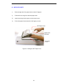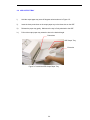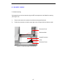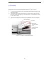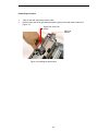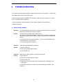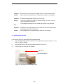
1
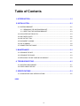
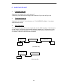
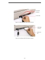
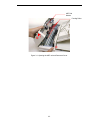
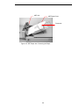
ScanPartner 620C Image Scanner
User's Manual
(Doc. No. 250-0062-0 Ver. 1.0)
FCC Radio Frequency Interference Statement
This equipment has been tested and found to comply with the limits for a class B digital
device, pursuant to Part 15 of the FCC rules. These limits are designed to provide
reasonable protection against harmful interference in a residential installation. This
equipment generates, uses, and can radiate radio frequency energy and, if not installed and
used in accordance with the instruction manual, may cause harmful interference to radio
communication. However, there is no guarantee that interference will not occur in a particular
installation. If this equipment does cause harmful interference to radio or television reception,
which can be determined by turning the equipment off and on, the user is encouraged to try to
correct the interference by one or more of the following measures:
* Reorient or relocate the receiving antenna.
* Increase the separation between the equipment and receiver.
* Connect the equipment into an outlet on a circuit different from that to which the receiver is
connected.
* Consult the dealer or an experienced radio/TV technician for help.
CAUTION: Any changes or modifications not expressly approved by the manufacture of this
device could void the user's authority to operate the equipment.
ii
Table of Contents
1. INTRODUCTION ........................................................................................... 1-1
2. INSTALLATION ............................................................................................ 2-1
2.1 SHIPPING BRACKET ...................................................................................................2-1
2.1.1 REMOVING THE SHIPPING BRACKET.............................................................2-1
2.1.2 REFITTING THE SHIPPING BRACKET .............................................................2-3
2.2 SCSI INTERFACE DEVICE ID ......................................................................................2-3
2.3 ADF PAPER CHUTE.....................................................................................................2-5
2.4 ADF OUTPUT TRAY.....................................................................................................2-6
2.5 DOCUMENT LOADING.................................................................................................2-7
2.6 ADF SCANNING ...........................................................................................................2-8
2.7 CONNECTING THE CABLE..........................................................................................2-9
3. MAINTENANCE ............................................................................................ 3-1
3.1 CLEANING THE ADF....................................................................................................3-1
3.2 CLEANING THE GLASS ...............................................................................................3-3
3.3 REPLACING THE ADF SNAP-IN PAD MODULE ..........................................................3-4
4. TROUBLESHOOTING .................................................................................. 4-1
4.1 QUESTION AND ANSWER ..........................................................................................4-1
4.2 PAPER JAM IN THE ADF .............................................................................................4-3
5. SPECIFICATIONS......................................................................................... 5-1
5.1 SCANPARTNER 620C SPECIFICATIONS....................................................................5-2
INDEX
iii
1.
INTRODUCTION
Congratulations on your purchase of Fujitsu ScanPartner 620C Scanner.
Before you install and operate the new Scanner, please take a few minutes to read through this
manual. It provides you with the proper instructions on how to unpack, install, operate and
maintain the Scanner.
Figure 1-1 shows how the Scanner is packed. You can check all items against your “checklist”,
included with your Scanner.
Power Cable
Signal Cable
Optional Package
Driver Kit
Output Paper Rack
Scanner Body
Foam(Left)
Form(Right)
Carton
Figure 1-1 Scanner packing
1-1
2.
INSTALLATION
Please unpack the Scanner carefully, and check the contents against the checklist. If any items
are missing or damaged, please contact your authorized local dealer immediately.
Precautions
•
Keep the Scanner out of direct sunlight. Direct exposure to the sun or excessive heat may
cause damage to the unit.
•
Do not install the Scanner in a humid or dusty place.
•
Be sure to use the proper AC power source.
•
Place the Scanner securely on an even, flat surface. Tilted or uneven surfaces may cause
mechanical or paper-feeding problems.
•
Retain the Scanner box and packing materials for shipping purposes.
2.1 SHIPPING BRACKET
The Scanner has a bracket that locks the carrier mechanism for transportation purposes. This
bracket must be put into the use position before using the Scanner.
If the power is turned on before the bracket has been removed the PAPER JAM light will turn on.
Before proceeding, turn the power off, disconnect all cables and follow the instructions below to
remove the shipping bracket.
2.1.1 REMOVING THE SHIPPING BRACKET
i).
Carefully place the Scanner in an upright position on its front.
ii).
Using a suitable screwdriver, remove the screw and pull out the shipping bracket.(See
Figure 2-1)
iii).
Put the shipping bracket into the use position with the short side extending into the Scanner
base and secure it with the screw.(See Figure 2-2)
iv).
Carefully place the Scanner back into its normal position.
2-1
“Shipping
Position”
Figure 2-1 Removing the Shipping Bracket
“Use Position”
Figure 2-2 Securing the Shipping Bracket
2-2
2.1.2 REFITTING THE SHIPPING BRACKET
Whenever you need to move the Scanner to a new location it is advisable to refit the shipping
bracket to avoid causing damage to the Scanners’ internal mechanism. Please follow the
instructions below to refit the shipping bracket.
i). Turn off the Scanner power at the power on/off switch.
ii). Open the document cover.
iii). Turn off the Scanner.
Note: For steps (iv) to (vi) please refer to Figure 2-1 and 2-2.
iv). Carefully place the Scanner in an upright position on its front side.
v). Use a suitable screwdriver to remove the screw holding the shipping bracket in the use
position.
vi). Put the shipping bracket into the shipping position, with the long side extending into the
Scanner base. Secure it with the screw.
vii). Carefully place the Scanner back into its normal position.
2.2 SCSI INTERFACE DEVICE ID
When you have several devices on a SCSI chain, you may need to adjust the SCSI ID selector
setting located on the back of the Scanner. This setting assigns a specific "device ID" to the
Scanner. If the assignment conflicts with an existing SCSI device, please select a new ID. (See
Figure 2-3)
Note: The factory setting for Scanner is ID 6. Usually, ID 0 is assigned to an internal hard disk
drive, and ID 7, to SCSI adapter or host. ID 8 and 9 are not in actual use.
Using a suitable tool, turn the selector switch until the arrow points to the desired ID number.
2-3
SCSI ID Selector
On
Off
SCSI Termination
Switch
Figure 2-3 Adjusting the SCSI ID setting.
2-4
2.3 ADF PAPER CHUTE
i).
Raise the right side of the paper chute to about 45 degrees.
ii).
Pull down the wire leg from under the paper chute.
iii).
Insert the wire leg into the grips on the document cover.
iv).
Pull out the paper chute extension to the length you want.
ADF Paper Chute
Paper Chute
Extension
Document
Cover
Figure 2-4 Setting the ADF Paper Chute
2-5
2.4 ADF OUTPUT TRAY
i).
Hold the output paper tray some 30 degrees aslant as shown in Figure 2-5.
ii).
Insert the three protrusions on the output paper tray to the three slots on the ADF.
iii).
Release the paper tray gently. Make sure the tray is firmly attached to the ADF.
iv).
Pull out the output paper tray extension wire to the desired length.
Protrusions
ADF Output Tray
Extension
Figure 2-5 Install the ADF Output Paper Tray
2-6
2.5 DOCUMENT LOADING
For flatbed scanning
Documents that can not be scanned using the ADF can be placed on the flatbed for scanning.
(See Figure 2-6)
i).
Place the document to be scanned onto the document glass face down.
ii).
Position the document so that the upper-right corner is aligned with the reference mark.
Document Cover
Reference Mark
Original Document
Glass
Reference Frame
Figure 2-6 Place Document on the Scanner
2-7
2.6 ADF SCANNING
Standard paper size can be scanned automatically using the ADF. Refer to Figure 2-7.
i).
To prevent occasional paper jam when automatically feeding multiple documents, fan the
paper before loading.
ii).
Lift the balance wire and place the documents to be scanned onto the ADF paper chute
face down, with the leading edge in the auto feeder entrance. Let the balance wire rest on
the top of the documents.
iii).
Adjust the left and right guides so that they are snug against the sides of the documents.
Auto Feeder Hole
Left Guide
Balance Wire
Document (blank
side)
ADF Paper Chute
Right Guide
Figure 2-7 - Use ADF to Load Multiple Documents
2-8
2.7 CONNECTING THE CABLE
i).
Turning the Power Off
Depress the side marked “O” to turn the power off.
Connect the power cable and SCSI signal cable as shown in Figure 2-8 and Figure 2-9.
ii).
Turning the Power On
Depress the side marked “I” to turn the power on. The POWER LED will light. If not, please
check the power source.
iii).
SCSI Termination
The Fujitsu ScanPartner 620C comes complete with a built in SCSI terminator. If the Scanner is
the last device in a SCSI chain the terminator should be switched on. If the Scanner is not the
last device the terminator should be off. The terminator on/off switch is located on the back of
the Scanner, to the left of the SCSI cable connectors.
Host PC
Scanner
SCSI Device
Term.
Term.
(Terminator Off)
Host PC
Scanner
Term.
(Terminator On)
2-9
Power Switch
SCSI Port
Power Cable
Figure 2-8 ScanPartner 620C Power Cable Connection
SCSI Cable
Connector
To PC SCSI
Port
Figure 2-9 ScanPartner 620C SCSI Cable Connection
2-10
3.
MAINTENANCE
3.1 CLEANING THE ADF
Your Scanner is designed to be maintenance free. However, it still needs to be cleaned
occasionally to ensure optimum image quality and performance.
From time to time the pad assembly and feeding rollers may become contaminated with ink,
toner particles or paper dust. In this case the scanner may not feed documents smoothly or
several documents may feed at once. If this occurs please follow the cleaning procedures to
return your Scanner to its original state.
The cleaning procedures (Figure 3-1)
i).
Moisten a cotton swab with isoprophyl alcohol (95%). (Cleaner kits are available from
Fujitsu.)
ii).
Open the ADF unit by depressing the button • in front of the ADF unit, carefully open the
ADF to the left ‚. Wipe the feeding rollers by moving the swab from side to side. Rotate
the rollers forward with your finger and repeat the above cleaning procedures until the
rollers are clean. Be careful not to snag or damage the pick springs.
iii).
Wipe the pad in the direction from top to bottom. Be careful not to hook the pick springs.
iv).
Close the ADF unit. Your Scanner is now ready for use.
3-1
ADF Pad
Module
Feeding Roller
¬
Figure 3-1 Opening the ADF unit and Document Cover
3-2
3.2 CLEANING THE GLASS
The procedures:
i).
Soak a cotton swab with some isoprophy alcohol (95%).
ii).
Open the ADF unit and document cover as shown in Figure 6-2. Wipe the glass of flatbed
area and ADF area by moving the swab from side to side.
iii).
Close the ADF unit and document cover. Your Scanner is
now ready for use.
Glass
Figure 3-2 The Cleaning Area
3-3
3.3
REPLACING THE ADF SNAP-IN PAD MODULE
After scanning approximately 150,000 pages through the ADF, the pad spring may be worn out
and you may experience problems with document feeding. In this case, it is highly recommended
to replace the pad module with a new one. For ordering the pad module, please consult your
nearest dealer and follow the procedure below to replace it.
Disassembling Procedure
1.
Open the ADF front cover by depressing the ADF release button.
2.
Remove the ADF snap-in pad module by pulling out the upper part of the pad clamp as
shown in Figure 3-3.
Upper Part of ADF Pad Clamp
ADF Unit
ADF
Cover
ADF Release
Button
Figure 3-3 Remove the pad module
3-4
Assembling Procedure
1.
Take out the ADF pad module from the box.
2.
Hold the upper part of the pad clamp and place it gently to the pad holder as shown in
Figure 3-4.
Upper Part of the Pad
Clamp
ADF Pad
Module
Figure 3-4 Installing the pad module
3-5
4.
TROUBLESHOOTING
The Scanner will automatically perform a simple self-test each time it is turned on. This will help
spot major system errors in the Scanner itself.
When the test is initiated, the READY LED is flashing. When the test is completed, if no error
occur, the READY LED is steadily on.
If you have problems with the operation of your Scanner, please check the following
troubleshooting hints.
4.1 QUESTION AND ANSWER
Question:
The LED indicates that the Scanner is ready, but the Scanner does not respond
to the scan command form the host computer.
Answer:
a) Please check the signal cable is firmly seated,
and invoke the scan command again. If there is still no response, please reset
the Scanner by turning it off and then on again, and reboot your host computer
as well.
b) Check if the driver is correctly installed. You can use the DIAG.EXE file in
“Fujitsu Driver Kit” to check this out.
c) Try to select another port memory.
Question:
Paper becomes jammed during scanning.
Answer:
a) Open the ADF unit.
b) Pull out the jammed paper carefully.
c) Close the ADF unit.
Question:
More than one sheet of paper were fed into the Scanner.
Answer:
a) Open ADF unit.
b) Remove the multi-fed sheets of paper.
c) Close the ADF unit.
d) Flatten the corners and edges; loosen the paper before reloading it in the
paper guide.
e) Check the feeding roller condition and do the cleaning if necessary. (See
Chapter 3)
4-1
Question:
Paper becomes skewed in the Scanner.
Answer:
a) Check the feeding roller condition; do the cleaning if necessary. (See Section
3.1)
b) Use the paper guide when feeding the paper.
Question:
When I power on the Scanner, it makes noises and will not stand ready.
Answer:
There are two possibilities:
a) You forgot to remove the shipping retainer from the Scanner. Please remove
the shipping retainer first.
b) You did not place the Scanner on a flat desktop surface. This may cause the
Scanner to function improperly.
Question:
When I power on the Scanner, the lamp does not light.
Answer:
The possibilities are as follows:
a) The lamp is out of order. In that case, contact your authorized local dealer to
change the lamp. The life time of the lamp is about 5000 hours.
b) The fuse on main board of the Scanner is burned. Check the main board of
the Scanner. If the fuse is burned, put in a new fuse that is 250V/2A.
c) If the fuse burns again after the changing, it means the inverter of the lamp is
burned. Contact your authorized local dealer to replace the inverter.
Question:
Getting image from the Scanner is not a problem, but when scanning, the Scanner
or system will often crash.
Answer:
Please check
a) If the cable is firmly seated;
b) Only two SCSI terminators can be connected to your SCSI daisy chain. One is at
the end of the SCSI device, another is already in your host adapter.
4-2
Question:
While scanning, the Scanner often makes noises, or it scans back and forth.
Answer:
Please choose lower speed from the TWAIN user interface for low speed PC.
Question:
The scanned image always comes out to be too dark.
Answer:
a) Use your application to modify the Gamma setting to 2.2 and 1.8 for your
printer and monitor respectively.
b) Use Brightness setting from the TWAIN user interface to get a brighter
image.
Question:
The Scanner works well otherwise, but for the line art, the lines of which seem
much thicker than those of the original.
Answer:
Use the Brightness or Threshold setting to adjust the line art image.
4.2 PAPER JAM IN THE ADF
In the event of paper jam, please follow the procedures below.
i).
Press the ADF Release Button at the front left of the Scanner as shown in Figure 4-1. The
ADF cover will be released.
ii).
Open the ADF cover to the full open position as shown in Figure 4-2..
iii).
Pull the paper out of the ADF unit carefully.
ADF Cover
ADF Release Button
Figure 4-1 ADF Paper Jam - Opening the ADF.
4-3
ADF Unit
ADF Paper Chute
Document
Figure 4-2 ADF Paper Jam - Removing the Paper
4-4
5.
SPECIFICATIONS
All specifications are subject to change without notice.
The following can not be properly fed by ADF:
•
Paper with clip or staple attached;
•
Paper with ink not totally dry;
•
Paper with inconsistent thickness, such as envelopes;
•
Paper with wrinkles, curls, folds or tears;
•
Tracing paper;
•
Coated paper;
•
Carbonless paper;
•
Paper narrower than 3.5" or wider than 8.5";
•
Items other than papers, such as cloth, metal or OHP film;
•
Notched paper;
•
Paper with an odd (non-rectangular) shape;
•
Very thin paper.
Please use the flatbed to scan documents that cannot be fed by the ADF.
5-1
5.1 SCANPARTNER 620C SPECIFICATIONS
v
1-pass colour
v
Flatbed with ADF built-in
v
36-bit colour
v
12-bit Grey Scale
v
Line Art/Halftone
v
Error Diffusion (single bit)
Optical Resolution
v
600 x 1200 dpi in a dpi increments
Light Source
v
Cold Cathode fluorescent lamp
ADF Capacity
v
50 pages
ADF Scanning Speed
v
20 PPM (200dpi, B/W mode, ADF)
Scanning Document Size Max.
v
ADF mode 8.5” x 14”
v
Flatbed mode 8.5” x 11.69”
Interface
v
SCSI-2
Power Requirement
v
100-240 Vac, 50-60Hz
Power Consumption
v
30 watts
Humidity
v
20% to 80%
Operation Temperature
v
10 to 35
Storage Temperature
v
-20 to 60
Dimension
v
570 x 350 x 166 mm(WxDxH)
Weight
v
Appropriate 26.5 lbs (12 kg)
Scanner Type
Scanning Mode
5-2
Index
A
P
ADF cover · 4-3
paper chute · 2-5
ADF Scanning · 2-8
paper chute extension · 2-5
paper jam · 2-8, 4-3
POWER LED · 2-9
B
protrusions · 2-6
balance wire · 2-8
R
C
READY LED · 4-1
Cleaning the ADF · 3-1
reference mark · 2-7
Cleaning the Glass · 3-3
refit the shipping bracket · 2-3
Connecting the Cable · 2-9
S
D
Scanner packing · 1-2
document cover · 2-5
SCSI chain · 2-3
Document Loading · 2-7
SCSI ID selector · 2-3
SCSI Termination · 2-9
O
shipping bracket · 2-1
shipping position · 2-3
output paper tray · 2-6
output paper tray extension · 2-6
U
use position · 2-1, 2-3
a