1
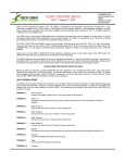
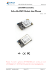
USR-WIFI232-G2 SPI Interface User Manual
http://en.usr.cn
USR-WIFI232-G2
SPI Interface User Manual V1.0
Product Features
Features::
Support UART/SPI two communication interface, user can freely choose
according to demand.
� UART communication mode, please refer to "USR-WIFI232 Low Power
WiFi Module User Manual V2.1"
� SPI communication, please refer to this documentation
Jinan USR IOT Technology Limited
Page 1 of 3
[email protected]
USR-WIFI232-G2 SPI Interface User Manual
http://en.usr.cn
1、Function Description
The USR-WIFI232-G2 module supports SPI data communication mode, the module
connect with SPI device via 5 pin, using interrupt trigger level to support different clock
polarity and phase four transmission modes, up to 6MHz rate.
1.1 Hardware connect
In SPI communication mode, the module operates in master mode, the connection
circuit as following.
Module SPI pins description:
SPI pins
WIFI232-G2
Function description
Module pin index
MOSI
Pin 30
SPI data out pin
MISO
Pin 27
SPI data in pin
CLK
Pin 28
SPI clock signal pin
CS
Pin 29
SPI select pins
INTR_I
Pin 23
SPI interrupt input pin, if the data
needs to be sent from the slave
device to the master device, the
slave device need to sends an
interrupt to the master device
through the INTR pin.
Low effective.
Master device read data from slave
device when INTR pin is low, and
stop read data when INTR pin is
high.
Jinan USR IOT Technology Limited
Page 2 of 3
[email protected]
USR-WIFI232-G2 SPI Interface User Manual
http://en.usr.cn
1.2 SPI Function Switch Method Description
Use AT command “AT+SPIEN=on” to open SPI mode, use “AT+SPIP” set
parameters.
� AT+ SPIEN set SPI mode, restart to effect, UART will automatic close
� AT+SPIP set SPI parameters; master mode, transmission mode, clock
frequency
AT+SPIP=<ms, mode, frequency><CR>
+ok<CR>< LF ><CR>< LF >
Parameters:
ms:
m, means master
mode: transmission mode, support 0,1,2,3
frequency: clock frequency, support 6MHz,3MHz,1.5MHz,750KHz,350KHz
Transmission mode corresponding clock polarity (CPOL) and clock phase (CPHA) in
the following table:
SPI Bus Protocol
Mode
CPOL
CPHA
0
0
0
1
0
1
2
1
0
3
1
1
1.3 SPI Function Using Introduction
1. SPI data sending (module � slave device)
When module sends data to slave device, INTR_I pin need to be a high level; and
the module will set CS pin low level. While transmitting, the MSB is first.
�module)
2. SPI data receiving (slave device
device�
When slave device sends data to the module, need to write data to the SPI buffer,
then set INTR_I pin low level, until the data is read by module, and then set INTR_I pin
high level.
Note: While reading data, module don
don’’t set CS pin low level.
Jinan USR IOT Technology Limited
Page 3 of 3
[email protected]