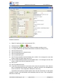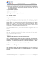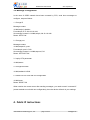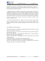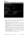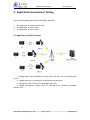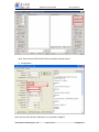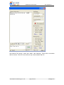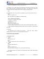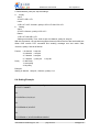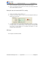
1
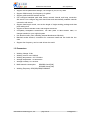
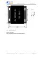
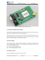
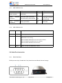
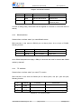
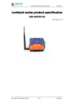
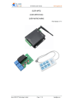
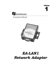
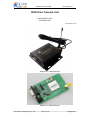
GPRS DTU User Manual www.tcp232.net GPRS Data Transmit Unit (USR-GPRS232-700) (USR-GPRS-701) File version: v1.6 Diagram 0-1 USR-GPRS-700 Diagram 0-2 USR-GPRS-701 Jinan USR IOT Technology Co., Ltd. page 1 of 34 [email protected] GPRS DTU User Manual www.tcp232.net Content GPRS Data Transmit Unit..................................................................................................................... 1 1. Product Description.........................................................................................................................3 1.1. Instruction........................................................................................................................... 3 1.2. Features............................................................................................................................... 4 1.3. Parameters...........................................................................................................................4 2. Install............................................................................................................................................... 5 2.1. Packing list........................................................................................................................... 5 2.1.1. USR-GPRS232-700....................................................................................................5 2.1.2. USR-GPRS232-701....................................................................................................5 2.2. Size and Diagram................................................................................................................. 5 2.2.1. USR-GPRS232-700....................................................................................................5 2.2.2. UISR-GPRS232-701...................................................................................................6 2.3. Antenna and SIM Card Installation..................................................................................... 7 2.4. Power Supply....................................................................................................................... 7 2.5. Indicator Lamps................................................................................................................... 7 2.5.1. USR-GPRS232-700....................................................................................................8 2.5.2. USR-GPRS232-701....................................................................................................8 2.6. Serial Port Instruction..........................................................................................................8 2.6.1. RS232 Definition.......................................................................................................8 2.6.2. RS485 definition....................................................................................................... 9 2.6.3. TTL definition........................................................................................................... 9 3. Parameter Configuration...............................................................................................................10 3.1. Hardware Connection....................................................................................................... 10 3.2. Parameter Configuration...................................................................................................10 3.3. Software configuration......................................................................................................10 3.3.1. Software interface introduce.................................................................................10 3.3.2. Software operation................................................................................................ 12 3.4. AT Command Configuration.............................................................................................. 12 3.5. Message Configuration......................................................................................................13 4. Public IP Instructions..................................................................................................................... 13 5. Application Environment Testing.................................................................................................. 16 5.1. Application of Public Server.............................................................................................. 16 5.2. Application of Router Transit.............................................................................................20 5.3. Application of Server Transit............................................................................................. 24 6. AT Command................................................................................................................................. 25 6.1. Set Key Parameter............................................................................................................. 25 6.2. Configure DTU business Packet.........................................................................................26 6.3. Set TCP/IP...........................................................................................................................27 6.4. Setting Example................................................................................................................. 29 7. FAQ.................................................................................................................................................30 Jinan USR IOT Technology Co., Ltd. page 2 of 34 [email protected] GPRS DTU User Manual www.tcp232.net 8. Contact...........................................................................................................................................32 9. File history..................................................................................................................................... 33 Jinan USR IOT Technology Co., Ltd. page 3 of 34 [email protected] GPRS DTU User Manual www.tcp232.net 1. Product Description 1.1.Instruction GPRS DTU (Data Transfer unit) is a wireless terminal equipment which can converter serial data to IP data or converter IP data to serial data, then transmit through wireless communication network. GPRS DTU is to use GPRS network to transmit data, it adopts industrial-grade embedded processor, embedded TCP/IP protocol stack. To provide users with virtual private networks, which is high speed, stable and reliable, data terminal online forever, and a variety of protocol conversion. At present, this device have already been used widely in M2M industry, such as Electric power industry: 1. Electric remote meter reading 2. Substation monitor 3. Power line monitor 4. Switch monitoring system on distribution network column Water conservancy industry: 1. Water quality monitor 2. Reservoir gate remote control system solutions 3. Water conservancy GPRS scheduling system application solutions 4. Water pipe network monitoring system 5. Reservoir automatic monitoring system Oil industry: 1. Oil and gas well remote monitor 2. GPRS remote oil field automation monitoring system 3. Gas pipeline network monitoring system solutions Municipal industry: 1. Street lamp remote monitoring management 2. Pipe network remote monitor 3. City energy consumption monitor Environmental protection industry: 1. Pollution source monitor 2. Atmospheric environment monitor 3. Noise monitor 4. Dust monitor Agricultural applications: 1. Greenhouse remote monitor 2. Aquaculture farmers monitor 3. Water pump monitor and control Other industries: 1. Warehouse monitor management 2. Elevator remote monitor 3. Remote crane management system 4. Industrial energy consumption monitoring 5. Gas station GPRS data acquisition system 6. GPRS weather information collection system 1.2.Features Easy to use, only configurate few parameters Use WAVECOM industrial module(701 use MD251 industrial module) Support TTL/RS232/RS485 interface, choose before purchase Using single module embedded protocol stack, no external CPU, higher stability Embedded TCP/IP protocol stack and GPRS technology Jinan USR IOT Technology Co., Ltd. page 4 of 34 [email protected] GPRS DTU User Manual www.tcp232.net Support remote parameters settings, can change IP, port, ect. by SMS Support GSM network, four frequency for global Support public and APN network access Can configure heartbeat pack data format, transmit interval, and keep connection with server. Can configure log pack data format and automatically establish network connection with server. Support data length control, can set the length of single sending package and data pack waiting time. Support ALWAYS ONLINE mode, and dropped reconnect. Completely transparent transmission, can take place of data transfer radio, no changes needed on your original system Use aluminum alloy case, shielding external disturbance effectively Matched sucker antenna, convenient for customers install and use inside the iron case Support four frequency, can be used all over the world 1.3.Parameters Working Voltage: 5-28v Working current: max 1200mA Working temperature: -20~75Celsius Storage temperature: -40~85Celsius Storage humidity: 5%~95%RH MAX transmit consumption: GSM900 class4(2W) DCS1800 class1(1W) Working Frequency: 850/900/1800/1900MHZ Jinan USR IOT Technology Co., Ltd. page 5 of 34 [email protected] GPRS DTU User Manual www.tcp232.net 2. Install 2.1.Packing list 2.1.1. USR-GPRS232-700 RS232 version: 1. USR-GPRS232-700 * 1 2. 5V power adapter * 1 3. RS232 serial cable * 1 4. User guide CD * 1 RS485 version: 1. USR-GPRS232-700 * 1 2. 5V power adapter * 1 3. User guide CD * 1 2.1.2. USR-GPRS232-701 RS232 version: 1. USR-GPRS232-701 * 1 (without shell) 2. 5V power adapter * 1 3. User guide CD * 1 2.2.Size and Diagram 2.2.1. USR-GPRS232-700 DTU can be used independently, which packaged in metallic casing. It is easy to install by the fixed position of the hole on both side. Details as follows (unit: mm) Jinan USR IOT Technology Co., Ltd. page 6 of 34 [email protected] GPRS DTU User Manual www.tcp232.net 2.2.2. UISR-GPRS232-701 PCB size: 80 * 50mm Other characteristic is same as 700 including drill hole. Jinan USR IOT Technology Co., Ltd. page 7 of 34 [email protected] GPRS DTU User Manual www.tcp232.net Diagram 2-1 USR-GPRS232-701(without shell) 2.3.Antenna and SIM Card Installation The antenna use SMA female base. Revolve the SMA male head to DTU antenna base, and ensure it is tightened, not to affect the signal quality. When install or take out SIM card, firstly use a spike to insert the little yellow point on the right side of SIM base, then SIM cutting ferrule is open. SIM card should be put into cutting ferrule in first while installing, ensure metal face outside. 2.4.Power Supply DTU is widely used in complex external environment. To adapt to its application and improve working stability of system, it use advanced power technologies, users can use our 5V 1A power adapter directly. 700 power supply ranges DC5~50V 701 power supply ranges DC5~28V 2.5.Indicator Lamps There are 3 indicators on DTU: “NET”, ”POW”, ”DATA” Jinan USR IOT Technology Co., Ltd. page 8 of 34 [email protected] GPRS DTU User Manual www.tcp232.net 2.5.1. USR-GPRS232-700 NET POW DATA Search network Quick flash Always on Off Search establish connection Quick flash when connected; Slow flash when disconnected On GPRS connection established Always quick flash On Slow flash when connected; off when disconnected Slow flash 2.5.2. USR-GPRS232-701 index name description 1 PWR On once power is on 2 NET State Module function: Off Module is not running; 64ms On/800ms Off Module does not find the network; 64ms On/3000ms Off Module find the network; 64ms On/300ms Off GPRS communication; 3 DATA When TCP link is established, it will on 2.6.Serial Port Instruction 2.6.1. RS232 Definition RS232 port use 9 pin, female hole. Only three lines are defined, the rest is empty. Jinan USR IOT Technology Co., Ltd. page 9 of 34 [email protected] GPRS DTU User Manual www.tcp232.net Diagram 2-2 RS232 interfaces ID Indicia Function Instruction 2 TXD Device data transmit RS232 level 3 RXD Device data receive RS232 level 5 GND Ground Communication common place Diagram 2-3 RS232 Pin description In order to debug easily, serial cable will be supplied for customer to connected with PC directly. 2.6.2. RS485 definition Please inform us before order if you need RS485 version. DB9 connector is the same as RS232 port on above photo. As to 6,9 pin of RS485, following function: ID Indicia Function Instruction 6 485-A A pin of RS485 RS485 level 9 485-B B pin of RS485 RS485 level Diagram 2-4 RS485 pin description As to RS485 equipment,we supply a DB9 pin connector and case for users make RS485 cables by themself. 2.6.3. TTL definition Please inform us before order if you need TTL version. DB9 connector is the same as RS232 port on above photo, use pin1, pin4 and pin9, following function: ID Indicia Function Instruction 1 RXD Device data transmit RS232 level 4 TXD Device data receive RS232 level 5 GND Ground Communication common place Diagram 2-5 TTL pin description Jinan USR IOT Technology Co., Ltd. page 10 of 34 [email protected] GPRS DTU User Manual www.tcp232.net 3. Parameter Configuration 3.1.Hardware Connection Configuration Before configuration, you need to connect DTU with PC by serial cable and power on. 3.2.Parameter Configuration Software: Configuration by software in CD. Easy to configurate through PC . Command: Configuration by AT command. In this case, users just need serial communication program. Message: configuration by sending sms. 3.3.Software configuration 3.3.1. Software interface introduce DTU access into AT command mode automatically after power on, within 2~40s, users can set parameters by serial port; If not, DTU will access to working mode, you need to set by sms after preparation of the GSM network. Free setup software is supplied, double-click to run, “USR-GPRS-DTU V1.0.exe”, reference as below: Jinan USR IOT Technology Co., Ltd. page 11 of 34 [email protected] GPRS DTU User Manual www.tcp232.net Software instruction: 1) Select PC serial port which connected with DTU 2) Serial port status: open closed 3) 4) 5) 6) 7) 8) 9) PC Baud rate( Default 115200 is okay. Will be modified according to (9) ) PC Parity bit/data/stop bit( Default value.Will be modified according to (10) ) Set DTU APN account Set DTU destination IP or domain name Set DTU network protocol Set DTU destination port Set DTU baud rate(Recommend default value 115200. If it is changed, the user also need to modify the above baud rate of PC. 10) Set DTU parity/data/stop bit(Recommend default value . If it is changed, the user also need to modify these above parameters of PC) 11) Set DTU ID 12) Set DTU heartbeat format 13) If specified need automatic reconnection when start the network link, then after the link is accidentally disconnected, waiting for <interval> seconds, will reestablish the server connection. This configuration effective for client only. If specified need sending heartbeat packet when start the network link, in links space <interval> seconds, will automatically send heartbeat packet to server. This configuration effective for client only. Jinan USR IOT Technology Co., Ltd. page 12 of 34 [email protected] GPRS DTU User Manual www.tcp232.net 14) Device receive<waiting data size> bytes data, immediately sent to connected server. 15) When serial port receive less <wait for data size> bytes data, and the module waiting for <waiting data timeout> milliseconds later, still didn't receive serial data, then will start sending buffer data. 16) Restore default configuration 17) Read current configuration 18) Save current settings 19) Message area, show configuration information 3.3.2. Software operation Configuration instruction 1. If you have already set up the IP and port number, after powering on, the power indicator light, the network indicator starts to flash quickly, when find network, the network indicator flashes once per second, then start mount GPRS network now. The network indicator flashes quickly, if you find the network in about 10-30s, then the network indicator flash quickly and the DATA indicator light and start flashing. It express that the device access to DTUGPRS transparent transmission mode. 2. 2s later after DTU powered on, you can make AT command configuration within 2~30 seconds Operation: Make sure serial cable connected with PC, software running and serial port opening. When DTU powered on again, it will show: “+BATS: 0 @@Ver:V01_B01_025-DTU-01, Build Time:2012/12/27 14:08” When it shows “device started, please finish read and configuration within 15 seconds”, then click "configure all parameters” (This operation should be finished before DTU mount GPRS, about 10-30 seconds. During this time, you can make the operation of reading, configuration; If overtime, you will need power on and operate again) 3.4.AT Command Configuration Open serial testing software, and serial port corresponding with PC, power on again, the same steps as “3.3.2 software operation”. AT commands please refer to “6. AT commend instruction” Jinan USR IOT Technology Co., Ltd. page 13 of 34 [email protected] GPRS DTU User Manual www.tcp232.net 3.5.Message Configuration In the case of GPRS network have been mounted by DTU, send short messages to configure, steps as follows: 1. Change IP Message content 111888,setip:0,<ipaddr> For example, IP is 182.32.116.166 So message content is 111888,setip:0,182.32.116.166 Return: SETIP OK 2. Change port Message content: 111888,setport:0,<port> For example, port is 7100 So message content is 111888,setport:0,710 Return: SETPORT OK 3. Inquiry DTU parameter 111888,status 4. Change Bund rate 111888,setbaud:115200 5. Restart DTU to work with new configuration 111888,reset Return: RESET OK When receive the correct return after sending messages, you need to send “command 5” (restart module to work with new configuration), then the device will work in your settings. 4. Public IP Instructions Jinan USR IOT Technology Co., Ltd. page 14 of 34 [email protected] GPRS DTU User Manual www.tcp232.net DTU data can not be sent to device which has not been connected to internet or intranet. So public IP must be used in DTU application. Following is the description of public IP Public IP is the address that the online PC obtained from Internet. PC with public IP and PC on Internet can access to each other. NAT(Network Address Translator) realize intranet IP interconversion with public IP, transform mass intranet IP to one or less public IP addresses separately, to reduce the occupation of public IP address. The most typical application of NAT: In LAN, only need one computer connected to the Internet, you can use NAT to share Internet connection, made other computers in LAN can also surf the Internet. With NAT protocol, computers in LAN can get access to the computers on Internet, but computers on Internet cannot access to computers in LAN. On windows operating system, the software of Internet connection sharing, sygate, winroute, unix/linux natd etc. all use NAT protocol to share Internet connection. The intranet internet access mode provided by ISP(Internet Service Provider) is based on NAT protocol. The classification of public IP address Class A: From 1.0.0.0 to 127.255.255.255, assigned to large network which has a large number of hosts but with fewer LANs. Class B: From 128.0.0.0 to 191.255.255.255, generally used for international companies and government agencies Class C: From 192.0.0.0 to 223.255.255.255, generally used for small companies, campus network and research institutions,etc Class D: From 224.0.0.0 to 239.255.255.255, used for special purpose, also called “broadcast address” Class E: From 240.0.0.0 to 255.255.255.255, Temporary retention To judge if the computer has a public IP, you can operate like this to check: Start- Run- input CMD- then Enter- input ”ipconfig/all”. As following picture: 180.186.12.99 is belong to Class B, it is an effective public IP address. Jinan USR IOT Technology Co., Ltd. page 15 of 34 [email protected] GPRS DTU User Manual www.tcp232.net Generally, we can distinguish whether the IP is public IP through following method: Usually, the machine that Telecom and Netcom through adsl dial-up obtain IP address, it should be public IP; Railtom broadband has NAT address translation, not public IP. Cable modems for dial-up Internet IP address, also public IP. GPRS wireless card (for laptop wireless Internet), the IP is Mobile GPRS internal IP, but because for GPRS DTU, they are from the same network, so they can also be used for connectivity. If users access to Internet through a router, and the router address is not the public IP through NAT translation, then we can adopt router port mapping, so the data can be forwarded through a router to your computer (Specific application diagram reference to chapter 5.2) If the machines IP is dynamic public IP, means the Internet IP is not fixed, it requires a dynamic DNS software installed on the PC. DTU support DNS, so as long as users’ applying domain name remains the same, DTU can also connect with them. There are many free DNS and domain name of the companies now, such as PeanutHull and Secco communication software. If your public IP address problem has been solved, so your PC will have the condition as DTU data collection center, then you can test and use DTU. Jinan USR IOT Technology Co., Ltd. page 16 of 34 [email protected] GPRS DTU User Manual www.tcp232.net 5. Application Environment Testing There are three application environment testing, as belows: 1. 2. 3. The application of public network server The application of router transit The application of server transit 5.1.Application of Public Server 1.Testing target: Server software and local device can be in two way transmission by DTU 2.Testing request: DTU serial port connected with PC serial port 3.Testing tool: USR-TCP-232-Test debugging tool, DTU 4.Testing environment: Target server IP “180.186.12.99”, Listening port”9696”, protocol”TCP” Jinan USR IOT Technology Co., Ltd. page 17 of 34 [email protected] GPRS DTU User Manual www.tcp232.net Note: Here we use USR-TCP232-Test to simulative network server 5.Configuration Note: We use China Unicom SIM Card, so it should be “UNINET” Jinan USR IOT Technology Co., Ltd. page 18 of 34 [email protected] GPRS DTU User Manual www.tcp232.net Power on and configurate DTU to, set the destination IP to server IP, destination port to server port, and baud rate default, then close the setup software. Open USR-TCP232-Test, start the serial port that connect with DTU(Mine is Com1) Click “Send”, the server displays: Jinan USR IOT Technology Co., Ltd. page 19 of 34 [email protected] GPRS DTU User Manual www.tcp232.net Already received data from DTU, click “send” on server side Jinan USR IOT Technology Co., Ltd. page 20 of 34 [email protected] GPRS DTU User Manual www.tcp232.net The local can also receive data from server 5.2.Application of Router Transit Jinan USR IOT Technology Co., Ltd. page 21 of 34 [email protected] GPRS DTU User Manual www.tcp232.net 1.Testing target: DTU send data to router, then router forward the data to destination PC 2.Testing request: DTU serial port connected with PC serial port 3.Testing tool: USR-TCP-232-Test debugging tool, DTU 4.Testing environment: Given router public network IP “60.208.252.67”, and has been set “port forwarding”. Forward port 9696 to the destination PC. Log in router page and set, for example, we use D-LINK router, steps: “ Internet connection” -->”Advanced”, as following picture: Restart router after finish settings. 5.Configuration Jinan USR IOT Technology Co., Ltd. page 22 of 34 [email protected] GPRS DTU User Manual www.tcp232.net Set destination IP to router public network IP, remote port “9696”, net protocol “TCP”. Power on DTU again, click “Write All Config”, then close the software. Open USR-TCP232-Test, as follows: Jinan USR IOT Technology Co., Ltd. page 23 of 34 [email protected] GPRS DTU User Manual www.tcp232.net Set protocol”TCP Server”, server port “9696”, click “listening”. There will be connection after a moment. Then DTU can have two way communication with PC. Jinan USR IOT Technology Co., Ltd. page 24 of 34 [email protected] GPRS DTU User Manual www.tcp232.net 5.3.Application of Server Transit In this mode, DTU data will be sent to our company server, and then the server forward data to destination DTU, to achieve remote communication between two DTU. This function need the supporting of transfer program on server. We can supply a simple transfer sample testing program. Picture as follows: Jinan USR IOT Technology Co., Ltd. page 25 of 34 [email protected] GPRS DTU User Manual www.tcp232.net 6. AT Command AT+ command use command line that based on ASCII code, command format as follows: <CR> <LF> means carriage returns, line feeds <CR> means “\r”, decimal ASCLL code is 13, hexadecimal code is 0x0D; <LF> means '\n', ASCII code is 10, hexadecimal is 0x0A <CR> <LF> means Carriage return, line feed. Pls input carriage returns and line feed but not those characters. 6.1.Set Key Parameter 1. Set DTU APN account (Default: Mobile CMENT) Send AT+CSTT=<apn><CR><LF> Note: <apn> is character string return <CR><LF>OK<CR><LF> For example: China Unicom: AT+CSTT="UNINET"<CR><LF> China Mobile: AT+CSTT="CMNET"<CR><LF> Jinan USR IOT Technology Co., Ltd. page 26 of 34 [email protected] GPRS DTU User Manual www.tcp232.net 2. Set DTU automatic startup mode, automatic reconnect waiting time after off line Send AT+CIPCFG=<auto_start>,<keepalive_wait>,<hex_packet>,<wait_time>,<wait_data_len ><CR><LF> return <CR><LF>OK<CR><LF> Parameter instructions parameters value instructions <auto_start> [0], 0-1 This specifies whether the module automatic recovery to original saved network connection context(including TCP/UDP connections, transparent transmission mode etc.), need AT + CIPSCONT command cooperate to use <keeplive_wait> [50], 1-86400 If specified need automatic reconnection when start the network link, then after the link is accidentally disconnected, waiting for <keeplive_wait> seconds, will reestablish the server connection. This configuration effective for client only. If specified need sending heartbeat packet when start the network link, in links space <keeplive_wait> seconds, will automatically send heartbeat packet to server. This configuration effective for client only. <hex_packet> 0-1 Whether internal hexadecimal text <wait_time> [0], 0-3600000 Unit: ms, effective in transparent transmission mode only When serial port receive less <wait_data_len> bytes data, and the module waiting for <wait_time> milliseconds later, still didn't receive serial data, then will start sending buffer data <wait_data_len> [0], 0-65535 Unit: byte, effective in transparent transmission mode only Module will send to connected server immediately after receiving <wait_time_len> bytes data command need be sent in 6.2.Configure DTU business Packet With AT+CIPPACK command to set data format of each DTU business packet. Jinan USR IOT Technology Co., Ltd. page 27 of 34 [email protected] GPRS DTU User Manual www.tcp232.net When the module is establishing a connection,which specifies send some command protocol packet, such as register packet 、 heartbeat packet. Parameter definition is as belows: 0 - Heartbeat packet 1 - Device register packet (Device ID) a. Heartbeat packet set Send AT+CIPPACK=0,<keepalive_packet><CR><LF> Return <CR><LF>OK<CR><LF> Note: <Keepalive_packet> is hexadecimal character string b. Device register packet (Device ID) set Send AT+CIPPACK=1,<register_packet><CR><LF> Return <CR><LF>OK<CR><LF> Note: < register_packet> is hexadecimal character string The data format definition of heartbeat packet or other data packet, each byte is called Hexadecimal character string, maximum support 80 bytes hexadecimal heartbeat packet. Example: AT+CIPPACK=0,"4C4F47" Configure DTU heartbeat packet data format AT+CIPPACK=1, "4C4F47494E3A31303031" set module register packet “LOGIN:1001” 6.3.Set TCP/IP 1. Link Mode: Support single link mode only, as this device in transparent transmission mode Configure single link mode Send AT+CIPMUX=0<CR><LF> Return <CR><LF>+CIPMUX:0<CR><LF>OK<CR><LF> Configure common data mode Send AT+CIPMODE=1<CR><LF> Return Jinan USR IOT Technology Co., Ltd. page 28 of 34 [email protected] GPRS DTU User Manual www.tcp232.net <CR><LF>+CIPMODE:1,0<CR><LF>OK<CR><LF> 2. Configure a TCP or UDP client link, and automatic reconnection( Only start one client link in single link mode). All parameter will be kept in the module after running this command. Note: Need configure APN account of GPRS, method as follows: Send AT+CIPSCONT=<mux>,<net_protocol>,<ip_address>,<ip_port><link_mode><CR><LF> Return <CR><LF>OK<CR><LF> Note: <net_protocol>,<ip_address> is character string <mux>: Single link mode, default 0 <net_protocol>: Network protocol type <ip_address>: IP address <ip_port>: Port <link_mode>: Link mode 0:Don not need to keep long link 1: Specify whether it need reconnect to server, after the link idle specified time value 2: Send customized heartbeat packet and keep long link, after link in specified idle time value For example AT+CIPSCONT=0,"TCP","182.32.112.178",7000,2 single link mode, network protocol is TCP, IP is 182.32.112.178, port 7000, link mode is 2 6.4. Set Serial port parameter 1. Baud rate operation a. Inquiry Send AT+CIPR?<CR><LF> Return <CR><LF>+CIPR:<rate><CR><LF>OK<CR><LF> b. Setting Send AT+CIPR=<rate><CR><LF> Return <CR><LF>OK<CR><LF> Baud rate setting successfully. Then, work as per new baud rate. <rate> Range of value: 110, 300, 600, 1200, 4800, 9600, 14400, 19200, 38400, 56000, 57600, 115200 Jinan USR IOT Technology Co., Ltd. page 29 of 34 [email protected] GPRS DTU User Manual www.tcp232.net 2. Serial data bit, parity bit, stop bit settings a. Inquiry Send AT+ICF?<CR><LF> return <CR><LF>+ICF:<format>,<parity><CR><LF>OK<CR><LF> b. Setting Send AT+ICF=<format>,<parity><CR><LF> Return <CR><LF>OK<CR><LF> Setting successfully. Then, work as per new data bit, parity bit, stop bit. With this command, can set start/ stop(asynchronous) frame format of the local serial port. When DCE receive DTE command and sending message text and result code, <format>,<parity> format as follows: Format: Parity 1: 8 data bit 2 stop bit 3: 8 data bit 1 stop bit 4: 7 data bit 2 stop bit 5: 7 data bit 1 parity bit 0: odd Parity 1: even parity 3: No parity 1 stop bit Example: Setting: 8 data bit, 1 stop bit, <format>,<parity>=3,3 6.4.Setting Example //Power on, within 2-30 seconds, configure as follows: AT+CSTT="CMNET" OK AT+CIPCFG=1,50,0,0,0,0 OK AT+CIPPACK=0,"4C4F47" OK AT+CIPPACK=1,"4C4F47494E3A31303031" Jinan USR IOT Technology Co., Ltd. page 30 of 34 [email protected] GPRS DTU User Manual www.tcp232.net OK AT + CIPMUX = 0 +CIPMUX: 0 OK AT + CIPMODE = 1 +CIPMODE: 1, 0 OK AT+CIPSCONT=0,"TCP","124.128.16.120", 10000,2 OK AT+ICF=3,3 OK AT+CIPR=115200 OK 7. FAQ Network can not connect to the server Please follow the following steps to troubleshoot 1) Use this software to read DTU device 2) configuration, to check destination IP, port, APN account and so on Check SIM card model, make sure it has opened GPRS flow, not owning money, make sure the card is plugged in well, antenna connection, power indicator light 3) Use this software establish a TCP Client on a PC which can connect to Internet, then connect with the server. If connection is ok, the Jinan USR IOT Technology Co., Ltd. page 31 of 34 [email protected] GPRS DTU User Manual 4) www.tcp232.net server is working well, otherwise, the server may have some problems If step 1) 2) 3) all right, but DTU still can not connect, pls change another SIM card or check hardware connection Serial port can not connect with DTU to config 1) 2) Confirm your interface, RS232, RS485 or TTL Computer com baudrate, default is 115200, if you have changed this before, pls use the new one as you set 3) For RS232 interface, pls use the matched serial cable we send in your package; for RS485 interface, use qualified RS232 to RS485 adapter(recommend HEXIN active RS232 to RS485 adapter); for TTL interface, need serial to TTL level conversion then connect with PC SIM Card Do not support 3G, EDGE and CDMA Jinan USR IOT Technology Co., Ltd. page 32 of 34 [email protected] GPRS DTU User Manual www.tcp232.net 8. Contact Company: Jinan USR IOT Technology Co., Ltd Address: 1-523, Huizhan Guoji Cheng, Gaoxin Qu, Jinan, Shandong, China Tel: 86-531-55507297 86-531-88826739-803 Web: www.tcp232.net Email: [email protected] Jinan USR IOT Technology Co., Ltd. page 33 of 34 [email protected] GPRS DTU User Manual www.tcp232.net 9. File history V1.0 V1.5.4 V1.6 file established add radio consumptionand 4 fre description add GPRS232-701 description Jinan USR IOT Technology Co., Ltd. page 34 of 34 [email protected]