1
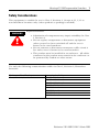
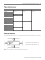
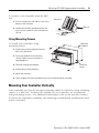
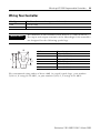
Installation Instructions
MicroLogix™ 1000 Programmable Controllers
Catalog Numbers 1761-L10BWA, -L10BWB, -L10BXB, -L16AWA, -L16BWA,
-L16BWB, -L16BBB, -L16NWA, -L16NWB, -L20AWA-5A, -L20BWA-5A,
-L20BWB-5A, -L32AAA, -L32AWA, -L32BWA, -L32BWB, -L32BBB
http://literature.rockwellautomation.com/idc/groups/literature/documents/in/
1761-in001_-mu-p.pdf
FR
Cette publication est disponible en français sous forme électronique (fichier PDF). Pour la
télécharger, rendez-vous sur la page Internet indiquée ci-dessus.
IT
Questa pubblicazione è disponibile in Italiano in formato PDF. Per scaricarla collegarsi al sito
Web indicato sopra.
DE
Diese Publikation ist als PDF auf Deutsch verfügbar. Gehen Sie auf die oben genannte
Web-Adresse, um nach der Publikation zu suchen und sie herunterzuladen.
ES
Esta publicación está disponible en español como PDF. Diríjase a la dirección web indicada
arriba para buscar y descarga esta publicación.
PT
Esta publicação está disponível em portugués como PDF. Vá ao endereço web que aparece
acima para encontrar e fazer download da publicação.
Installation Instructions
MicroLogix™ 1000 Programmable Controllers
Catalog Numbers 1761-L10BWA, -L10BWB, -L10BXB, -L16AWA, -L16BWA,
-L16BWB, -L16BBB, -L16NWA, -L16NWB, -L20AWA-5A, -L20BWA-5A,
-L20BWB-5A, -L32AAA, -L32AWA, -L32BWA, -L32BWB, -L32BBB
Topic
Page
Important User Information
4
Overview
5
Catalog Number Detail
5
Related Publications
6
Safety Considerations
7
Physical Dimensions
9
Mounting Your Controller Horizontally
10
Wiring Your Controller
13
Grounding Your Controller
15
Surge Suppression
16
Sinking and Sourcing
19
Wiring Your Analog Channels
20
Specifications
21
4
MicroLogix™ 1000 Programmable Controllers
Important User Information
Because of the variety of uses for the products described in this publication, those
responsible for the application and use of these products must satisfy themselves
that all necessary steps have been taken to assure that each application and use
meets all performance and safety requirements, including any applicable laws,
regulations, codes and standards. In no event will Allen-Bradley be responsible or
liable for indirect or consequential damage resulting from the use or application of
these products.
Any illustrations, charts, sample programs, and layout examples shown in this
publication are intended solely for purposes of example. Since there are many
variables and requirements associated with any particular installation, Allen-Bradley
does not assume responsibility or liability (to include intellectual property liability)
for actual use based upon the examples shown in this publication.
Allen-Bradley publication SGI-1.1, Safety Guidelines for the Application, Installation
and Maintenance of Solid-State Control (available from your local Allen-Bradley
office), describes some important differences between solid-state equipment and
electromechanical devices that should be taken into consideration when applying
products such as those described in this publication.
Reproduction of the contents of this copyrighted publication, in whole or part,
without written permission of Rockwell Automation, is prohibited.
Throughout this publication, notes may be used to make you aware of safety
considerations. The following annotations and their accompanying statements help
you to identify a potential hazard, avoid a potential hazard, and recognize the
consequences of a potential hazard:
WARNING
!
ATTENTION
Identifies information about practices or circumstances that
can cause an explosion in a hazardous environment, which
may lead to personal injury or death, property damage, or
economic loss.
Identifies information about practices or circumstances that
can lead to personal injury or death, property damage, or
economic loss.
!
Publication 1761-IN001C-EN-P - March 2008
MicroLogix™ 1000 Programmable Controllers
IMPORTANT
5
Identifies information that is critical for successful application
and understanding of the product.
Overview
Install your controller using these installation instructions. The only tools you
require are a Flat head or Phillips head screwdriver and drill.
Catalog Number Detail
The catalog number for the controller is composed of the following:
1761 - L 20 A W A - 5 A
Analog I/O
Bulletin Number
Controller
Number of Digital I/O
Input Type:
A = 120V ac
B = 24V dc
N = 24V ac or 24V dc
Number of Analog I/O:
4 Inputs, 1 Output
Power Supply
A = 120/240V ac
B = 24V dc
Output Type:
A = Triac
B = 24V dc FET
W = Relay
X = Relay/24V dc FET
Publication 1761-IN001C-EN-P - March 2008
6
MicroLogix™ 1000 Programmable Controllers
For More Information
Related Publications
For
Refer to this Document
Pub. No.
A description on how to use your MicroLogix 1000
programmable controllers. This manual also contains
status file data and instruction set information.
MicroLogix 1000 Programmable
Controllers User Manual
1761-6.3
A procedural manual for technical personnel who use the MicroLogix 1000 with Hand-Held
Programmer (HHP) User Manual
Allen-Bradley Hand-Held Programmer (HHP) to monitor
and develop control logic programs for the MicroLogix
1000 controller.
1761-6.2
More information on proper wiring and grounding
techniques.
1770-4.1
Industrial Automation Wiring and
Grounding Guidelines
The procedures necessary to install and connect the AIC+ Advanced Interface Converter
and DNI.
(AIC+) and DeviceNet Interface
(DNI) Installation Instructions
1761-5.11
A more detailed description on how to install and use your AIC+ Advanced Interface Converter 1761-6.4
AIC+ Advanced Interface Converter.
User Manual
A more detailed description on how to install and use your DeviceNet Interface User Manual
DeviceNet Interface.
1761-6.5
A more detailed description on how to install and use your Ethernet Interface User Manual
Ethernet Interface.
1761-UM006
If you would like a manual, you can:
• download a free electronic version from the internet:
http://literature.rockwellautomation.com
• purchase a printed manual by contacting your local Allen-Bradley distributor
or Rockwell Automation representative
Publication 1761-IN001C-EN-P - March 2008
MicroLogix™ 1000 Programmable Controllers
7
Safety Considerations
This equipment is suitable for use in Class I, Division 2, Groups A, B, C, D or
non-hazardous locations only (when product or packing is marked).
WARNING
!
Explosion Hazard:
• Substitution of components may impair suitability for Class
I, Division 2.
• Do not replace components or disconnect equipment
unless power has been switched off and the area is
known to be non-hazardous.
• Do not connect or disconnect connectors while circuit is
live unless area is known to be non-hazardous.
• This product must be installed in an enclosure. All cables
connected to the product must remain in the enclosure or
be protected by conduit or other means.
Use only the following communication cables in Class I, Division 2, Hazardous
Locations.
Environment Classification
Communication Cable
Class I, Division 2, Hazardous Environment
1761-CBL-PM02 Series C
1761-CBL-HM02 Series C
1761-CBL-AM00 Series C
1761-CBL-AP00 Series C
2707-NC8 Series B
2707-NC9 Series B
2707-NC10 Series B
2707-NC11 Series B
Publication 1761-IN001C-EN-P - March 2008
8
MicroLogix™ 1000 Programmable Controllers
Sécurité
Cet équipement est conçu pour être utilisé dans des environnements de Classe 1,
Division 2, Groupes A, B, C, D ou non dangereux (si indiqué sur le produit ou
l'emballage).
AVERTISSEMENT
!
Danger d'explosion :
• La substitution de composants peut rendre cet
équipement impropre à une utilisation en environnement
de Classe 1, Division 2.
• Ne pas remplacer de composants ou déconnecter
l'équipement sans s'être assuré que l'alimentation est
coupée et que l'environnement est classé non dangereux.
• Ne pas connecter ou déconnecter les connecteurs lorsque
le circuit est alimenté, à moins que l'environnement ne
soit classé non dangereux.
• Ce produit doit être installé dans un boîtier. Tous les
câbles qui lui sont connectés doivent rester dans le boîtier
ou être protégés.
N'utiliser que les câbles de communication suivants dans des environnements
dangereux de Classe 1, Division 2.
Classification d'environnement
Câble de communication
Environnement dangereux Classe 1, Division 2
1761-CBL-PM02 Série C
1761-CBL-HM02 Série C
1761-CBL-AM00 Série C
1761-CBL-AP00 Série C
2707-NC8 Série B
2707-NC9 Série B
2707-NC10 Série B
2707-NC11 Série B
Publication 1761-IN001C-EN-P - March 2008
MicroLogix™ 1000 Programmable Controllers
9
Physical Dimensions
Controller: 1761-
Length: mm (in.)
Depth: mm (in.)
Height: mm (in.)
L10BWA
120 (4.72)
73 (2.87)
80 (3.15)
L16BWA
L16NWA
L16AWA
133 (5.24)
L20AWA-5A
200 (7.87)
L20BWA-5A
L32AWA
L32BWA
L32AAA
L10BWB
120 (4.72)
40 (1.57)
L10BXB
L16BBB
L16BWB
L16NWB
L20BWB-5A
200 (7.87)
L32BBB
L32BWB
Controller Spacing
The following figure shows the recommended minimum spacing for the controller.
Top B
Side
Side
A
A
A. Greater than or equal to 50.8 mm (2 in.)
B. Greater than or equal to 50.8 mm (2 in.)
Bottom B
Note: The controller is shown horizontally mounted.
Publication 1761-IN001C-EN-P - March 2008
10
MicroLogix™ 1000 Programmable Controllers
Mounting Your Controller Horizontally
The controller should be mounted horizontally within an enclosure using either the
DIN rail or mounting screw option. Use the mounting template from the front of
this document to help you space and mount the controller properly.
ATTENTION
!
Be careful of metal chips when drilling mounting holes for
your controller. Drilled fragments that fall into the controller
could cause damage. Do not drill holes above a mounted
controller if the protective wrap is removed.
Using a DIN Rail
To install your controller on the DIN rail:
1. Mount your DIN rail. (Make sure that the
placement of the controller on the DIN rail
meets the recommended spacing
requirements. Refer to the mounting template
from the back of this document.)
Protective
Wrap
Side View
Mounting
Template
DIN Rail
2. Hook the top slot over the DIN rail.
3. While pressing the controller against the rail,
snap the controller into position.
4. Leave the protective wrap attached until you
are finished wiring the controller.
B
A
DIN Rail
C
Publication 1761-IN001C-EN-P - March 2008
Call-out
Dimension
A
84 mm (3.3 in.)
B
33 mm (1.3 in.) maximum
C
16 mm (0.63 in.)
MicroLogix™ 1000 Programmable Controllers
To remove your controller from the DIN
rail:
11
Side View
1. Place a screwdriver in the DIN rail latch at the
bottom of the controller.
DIN Rail
2. Holding the controller, pry downward on the
latch until the controller is released from the
DIN rail.
Using Mounting Screws
To install your controller using
mounting screws:
Mounting
Template
1. Remove the mounting template from the
back of this document.
2. Secure the template to the mounting
surface. (Make sure your controller is
spaced properly.)
3. Drill holes through the template.
Protective
Wrap
4. Remove the mounting template.
5. Mount the controller.
6. Leave the protective wrap attached until you are finished wiring the controller.
Mounting Your Controller Vertically
Your controller can also be mounted vertically within an enclosure using mounting
screws or a DIN rail. To insure the stability of your controller, we recommend
using mounting screws. For additional information, refer to the previous section.
To insure the controller's reliability, the following environmental specifications must
not be exceeded.
Publication 1761-IN001C-EN-P - March 2008
12
MicroLogix™ 1000 Programmable Controllers
Top
A
Side
Side
A
A
Bottom
A
Description:
Specification:
Operating Temperature
0°C to +40°C (+32°F to +113°F)(1)
Operating Shock
9.0g peak acceleration (11 ± 1 ms duration)
(Panel mounted)
3 times each direction, each axis
Operating Shock
7.0g peak acceleration (11 ± 1 ms duration)
(DIN rail mounted)
3 times each direction, each axis
(1)
DC input voltage derated linearly from +30°C (30V to 26.4V).
A. Greater than or equal to 50.8 mm (2 in.).
Note: When mounting your controller vertically, the nameplate should be facing
downward.
Publication 1761-IN001C-EN-P - March 2008
MicroLogix™ 1000 Programmable Controllers
13
Wiring Your Controller
Wire Type:
Wire Size: (2 wire maximum per terminal screw)
Solid
#14 to #22 AWG
Stranded
#16 to #22 AWG
IMPORTANT
The diameter of the terminal screw head is 5.5 mm (0.220 in.).
The input and output terminals of the MicroLogix 1000 controller
are designed for the following spade lugs:
W
X
L
E
C
Call-out
Dimension
C
6.35 mm (0.250 in.)
E
10.95 mm (0.431 in.) maximum
L
14.63 mm (0.576 in.)
W
6.35 (0.250 in.)
X
3.56 mm (0.140 in.)
C+X
9.91 mm (0.390 in.) maximum
We recommend using either of these AMP (or equal) spade lugs: part number
53120-1, if using 22-16 AWG, or part number 53123-1, if using 16-14 AWG.
Publication 1761-IN001C-EN-P - March 2008
14
MicroLogix™ 1000 Programmable Controllers
IMPORTANT
IMPORTANT
If you use wires without lugs, make sure the wires are securely
captured by the pressure plate. This is particularly important at
the four end terminal positions where the pressure plate does not
touch the outside wall of the controller.
Be careful when stripping wires. Wire fragments that fall into the
controller could cause damage. Remove the protective wrap after
wiring your controller. Failure to remove the wrap may cause the
controller to overheat.
Protective
Wrap
IMPORTANT
This symbol denotes a functional earth ground terminal
which provides a low impedance path between electrical
circuits and earth for non-safety purposes, such as noise
immunity improvement.
Publication 1761-IN001C-EN-P - March 2008
MicroLogix™ 1000 Programmable Controllers
15
Grounding Your Controller
In solid-state control systems, grounding helps limit the effects of noise due to
electromagnetic interference (EMI). Run the ground connection from the ground
screw of the controller (third screw from left on output terminal rung) to the
ground bus. Use the heaviest wire gauge listed for wiring your controller.
Protective Wrap
(remove after wiring)
ATTENTION
!
All devices connected to the user 24V power supply or to the
RS-232 channel must be referenced to chassis ground or
floating. Failure to follow this procedure may result in
property damage or personal injury.
Chassis ground, user 24V ground, and the RS-232 ground are
internally connected. You must connect the chassis ground
terminal screw to chassis ground prior to connecting any
devices.
On the 1761-L10BWB, -L10BXB, -L16BWB, -L16BBB,
-L16NWB, -L20BWB-5A, -L32BBB, and -L32BWB controllers,
the ground associated with the user supplied 24V DC input
power and chassis ground are internally connected.
You must also provide an acceptable grounding path for each device in your
application. For more information on proper grounding guidelines, see the
Industrial Automation Wiring and Grounding Guidelines, (publication 1770-4.1).
Publication 1761-IN001C-EN-P - March 2008
16
MicroLogix™ 1000 Programmable Controllers
Surge Suppression
Inductive load devices such as motor starters and solenoids require the use of some
type of surge suppression to protect the controller output contacts. Switching
inductive loads without surge suppression can significantly reduce the life
expectancy of relay contacts. By adding a suppression device directly across the
coil of inductive devices, you prolong the life of the output circuits. You also
reduce the effects of radiated voltage transients and prevent electrical noise from
radiating into system wiring and facility.
The following diagram shows an output with a suppression device. We
recommend that you locate the suppression device as close as possible to the load
device.
+dc or L1
VAC/DC
Suppression Device
Out 0
Out 1
ac or dc
Outputs
Out 2
Out 3
Out 4
Out 5
Out 6
Out 7
COM
dc COM or L2
If you connect a micro controller FET output to an inductive load, we recommend
that you use an 1N4004 diode for surge suppression, as shown in the illustration on
page 17.
Publication 1761-IN001C-EN-P - March 2008
MicroLogix™ 1000 Programmable Controllers
17
Suitable surge suppression methods for inductive load devices include a varistor, an
RC network, or, for dc loads, a diode. These components must be appropriately
rated to suppress the switching transient characteristic of the particular inductive
device. See the table on page 18 for recommended suppressors.
As the following diagram illustrates, these surge suppression circuits connect
directly across the load device. This reduces arcing and damage of the output
contacts. (High transients can cause arcing that occurs when switching off an
inductive device.)
Surge Suppression for Inductive ac Load Devices
Output Device
Output Device
Varistor
RC Network
Output Device
Diode (A surge suppressor
can also be used.)
If you connect a micro controller triac output to control an inductive load, we
recommend that you use varistors to suppress noise. Choose a varistor that is
appropriate for the application. The suppressors we recommend for triac outputs
when switching 120V ac inductive loads are a Harris MOV, part number V175
LA10A, or an Allen-Bradley MOV, catalog number 599-K04 or 599-KA04. Consult
the varistor manufacturer's data sheet when selecting a varistor for your application.
For inductive dc load devices, a diode is suitable. A 1N4004 diode is acceptable for
most applications. A surge suppressor can also be used. See the table on page 18
for recommended suppressors.
Publication 1761-IN001C-EN-P - March 2008
18
MicroLogix™ 1000 Programmable Controllers
Recommended Surge Suppressors
We recommend the Allen-Bradley surge suppressors shown in the following table
for use with Allen-Bradley relays, contactors, and starters.
Device
Coil Voltage
Suppressor Catalog
Number
Bulletin 509 Motor Starter
Bulletin 509 Motor Starter
120V ac
240V ac
599-K04(1)
Bulletin 100 Contactor
Bulletin 100 Contactor
120V ac
240V ac
199-FSMA1(2)
599-KA04(1)
199-FSMA2(2)
Bulletin 709 Motor Starter
120V ac
1401-N10
Bulletin 700 Type R, RM Relays
ac coil
None Required
Bulletin 700 Type R Relay
Bulletin 700 Type RM Relay
12V dc
12V dc
199-FSMA9
Bulletin 700 Type R Relay
Bulletin 700 Type RM Relay
24V dc
24V dc
199-FSMA9
Bulletin 700 Type R Relay
Bulletin 700 Type RM Relay
48V dc
48V dc
199-FSMA9
Bulletin 700 Type R Relay
Bulletin 700 Type RM Relay
115-125V dc
115-125V dc
199-FSMA10
Bulletin 700 Type R Relay
Bulletin 700 Type RM Relay
230-250V dc
230-250V dc
199-FSMA11
Bulletin 700 Type N, P, or PK Relay
150V max, ac or DC
700-N24(2)
Miscellaneous electromagnetic devices limited to
35 sealed VA
150V max, ac or DC
700-N24(2)
(1)
Varistor – Not recommended for use on relay outputs.
(2)
RC Type – Do not use with triac outputs.
Publication 1761-IN001C-EN-P - March 2008
MicroLogix™ 1000 Programmable Controllers
19
Sinking and Sourcing
Any MicroLogix 1000 DC input can be configured as sinking or sourcing depending
on how the DC COM terminal is wired.
Mode:
Definition:
Sinking
The input energizes when high-level voltage is applied to the input terminal (active
high). Connect the power supply VDC (-) to the corresponding DC COM terminal.
Sourcing
The input energizes when low-level voltage is applied to the input terminal (active low).
Connect the power supply VDC (+) to the corresponding DC COM terminal.
Sinking and Sourcing Wiring Examples
1761-L32BWA
Sourcing Inputs
Sinking Inputs
14-30 VDC
VDC (+) for Sourcing
VDC (-) for Sourcing
VDC (+) for Sinking
VDC (-)
for Sinking
+ 24V DC OUT
DC
COM
I/0
I/1
I/2
I/3
DC
COM
I/4
I/5
I/6
I/7
I/8
Sourcing Inputs
I/9
I/10
I/11
I/12
I/13
I/14
I/15 I/16
I/17
I/18
I/19
Sinking Inputs
14-30 VDC
VDC (+)
VDC (-) for Sinking
VDC (+)
for Sinking
VDC (-) for Sourcing
for Sourcing
+ 24V DC OUT
DC
COM
I/0
I/1
I/2
I/3
DC
COM
I/4
I/5
I/6
I/7
I/8
I/9
I/10
I/11
I/12
I/13
I/14
I/15 I/16
I/17
I/18
I/19
Publication 1761-IN001C-EN-P - March 2008
20
MicroLogix™ 1000 Programmable Controllers
Wiring Your Analog Channels
Analog input circuits can monitor current and voltage signals and convert them to
serial digital data. The analog output can support either a voltage or a current
function as shown in the following illustration.
Sensor 2
(V) Voltage
Sensor 3
(I) Current
Sensor 1
(V) Voltage
Jumper
unused
inputs.
I/10
I/11
IA
SHD
VAC
VDC
O/4
O/5
IA/0
V (+)
IA/1
V (+)
O/6
IA
(-)
IA
SHD
IA/2
I (+)
IA/3
I (+)
IA
(-)
NOT
OA
SHD
OA/0
V (+)
OA/0
I (+)
OA
(-)
O/7 USED
You can configure either voltage or
current output operation.
Sensor 4
(I) Current
- or meter
The controller does not provide loop power for analog inputs. Use a power supply
that matches the transmitter specifications as shown below.
2-Wire Transmitter
Power
Supply
+
-
3-Wire Transmitter
Power
Supply
+
-
Transmitter
Supply
Signal
GND
+
-
Controller
IA/0 - 3 (+)
IA (-)
Controller
+
-
4-Wire Transmitter
Power
Supply
Transmitter
IA/0 - 3 (+)
IA (-)
Transmitter
Supply
Signal
+
-
Publication 1761-IN001C-EN-P - March 2008
+
-
Controller
IA/0 - 3 (+)
IA (-)
MicroLogix™ 1000 Programmable Controllers
21
Minimizing Electrical Noise on Analog Controllers
Inputs on analog controllers employ digital high-frequency filters that significantly
reduce the effects of electrical noise on input signals. However, because of the
variety of applications and environments where analog controllers are installed and
operated, it is impossible to ensure that all environmental noise will be removed by
the input filters.
Several specific steps can be taken to help reduce the effects of environmental
noise on analog signals:
• install the MicroLogix 1000 system in a properly rated (i.e., NEMA)
enclosure. Make sure that the MicroLogix 1000 system is properly grounded.
• use Belden cable #8761 for wiring the analog channels, making sure that the
drain wire and foil shield are properly earth grounded.
• route the Belden cable separate from any ac wiring. Additional noise
immunity can be obtained by routing the cables in grounded conduit.
Grounding Your Analog Cable
Use shielded communication
cable (Belden #8761). The
Belden cable has two signal
wires (black and clear), one
drain wire, and a foil shield.
The drain wire and foil shield
must be grounded at one end
of the cable. Do not ground
the drain wire and foil shield
at both ends of the cable.
Foil Shield
Black Wire
Insulation
Drain Wire
Clear Wire
Specifications
Environmental Specifications (all MicroLogix controllers)
Description
Specification
Operating Temperature
0°C to +55°C (+32°F to +131°F) for horizontal mounting
0°C to +40°C (+32°F to +104°F) for vertical mounting(1)
Publication 1761-IN001C-EN-P - March 2008
22
MicroLogix™ 1000 Programmable Controllers
Description
Specification
Storage Temperature
-40°C to +85°C (-40°F to +185°F)
Operating Humidity
5 to 95% non-condensing
Agency Certification (when
product or packaging is
marked)
• C-UL Class I, Division 2 Groups A,B,C,D certified
(1)
• UL listed (Class I, Division 2 Groups A,B,C,D certified)
• CE/C-Tick compliant for all applicable directives
DC input voltage derated linearly from +30°C (30V to 26.4V).
General Specifications
Description:
Specification: 1761-L
16AWA 32AWA 10BWA 16BWA 32BWA 32AAA 10BXB 10BWB 32BWB
16NWA
16BBB 16BWB 32BBB
16NWB
Memory Size and
Type
1 K EEPROM (approximately 737 instruction words: 437 data words)
Power Supply
Voltage
85-264V ac, 47-63 Hz
Power
Supply
Usage
20.4-26.4V dc
120V ac
15 VA
19 VA
24 VA
26 VA
29 VA
16 VA
240V ac
21 VA
25 VA
32 VA
33 VA
36 VA
22 VA
24V dc
Power Supply Max
Inrush Current
Not Applicable
Not Applicable
5W
30A for 8 ms
30A for 4 ms
24V dc Sensor Power Not Applicable
(V dc at mA)
200 mA
Max Capacitive Load
(User 24V dc)
200 µF
7W
Not Applicable
Power Cycles
50,000 minimum
Vibration
Operating: 5 Hz to 2k Hz, 0.381 mm (0.015 in.) peak to peak/2.5g panel mounted,(1) 1hr
per axis
Non-operating: 5 Hz to 2k Hz, 0.762 mm (0.030 in.) peak to peak/5g, 1hr per axis
Shock(2)
Operating: 10g peak acceleration (7.5g DIN rail mounted)(3) (11±1 ms duration) 3 times
each direction, each axis
Non-operating: 20g peak acceleration (11±1 ms duration), 3 times each direction, each
axis
Terminal Screw
Torque
0.9 N-m maximum (8.0 in.-lbs)
Electrostatic
Discharge
EN 61000-2 at 8K V
Radiated
Susceptibility
EN 61000-3 at 10 V/m, 27 MHz - 1000 MHz; 3V/m, 87 MHz - 108 MHz, 174 MHz - 230
MHz, and 470 MHz - 790 MHz
Fast Transient
EN 61000-4 at 2K V Power Supply, I/O; 1K V Comms
Isolation
1500V ac
(1)
DIN rail mounted controller is 1g.
Publication 1761-IN001C-EN-P - March 2008
MicroLogix™ 1000 Programmable Controllers
(2)
Refer to page 12 for vertical mounting specifications.
(3)
Relays are derated an additional 2.5g on 32 pt. controllers.
23
Analog General Specifications
Description:
Specification: 1761-L
20AWA-5A
20BWA-5A
20BWB-5A
Memory Size and Type 1 K EEPROM (approximately 737 instruction words: 437 data words)
Power Supply Voltage
Power
Supply
Usage
85-264V ac, 47-63 Hz
20.4-26.4V dc
120V ac 20 VA
30 VA
240V ac 27 VA
38 VA
24V dc
Not Applicable
Not Applicable
10W
24V dc Sensor Power (V Not Applicable
dc at mA)
200 mA
Max Capacitive Load
(User 24V dc)
200 µF
Not Applicable
Power Cycles
50,000 minimum
Vibration
Operating: 5 Hz to 2k Hz, 0.381 mm (0.015 in.) peak to peak/2.5g panel mounted,(1) 1hr
per axis
Non-operating: 5 Hz to 2k Hz, 0.762 mm (0.030 in.) peak to peak/5g, 1hr per axis
Shock(2)
Operating: 10g peak acceleration (7.5g DIN rail mounted)(3) (11±1 ms duration) 3 times
each direction, each axis
Non-operating: 20g peak acceleration (11±1 ms duration), 3 times each direction,
each axis
Terminal Screw Torque 0.9 N-m maximum (8.0 in.-lbs)
Electrostatic Discharge EN 61000-2 at 8K V Discrete I/O
4K V Contact, 8K V Air for Analog I/O
Radiated Susceptibility EN 61000-3 at 10 V/m, 27 MHz - 1000 MHz
3 V/m, 87 MHz - 108 MHz, 174 MHz - 230 MHz, and 470 MHz - 790 MHz
Fast Transient
EN 61000-4 at 2K V Power Supply, I/O; 1K V Comms
Isolation
1500V ac
(1)
DIN rail mounted controller is 1g.
(2)
Refer to page 12 for vertical mounting specifications.
(3)
Relays are derated an additional 2.5g on 20 pt. controllers.
General Input Specifications
Description
Specification
100-120V ac Controllers
24V dc Controllers
Voltage Range
79 to 132V ac, 47 to 63 Hz
14 to 30V dc
On Voltage
79V ac min.
132V ac max.
14V dc min.
24V dc nominal
26.4V dc max. at +55°C (+131°F)
30.0V dc max. at +30°C (+86°F)
Off Voltage
20V ac
5V dc
Publication 1761-IN001C-EN-P - March 2008
24
MicroLogix™ 1000 Programmable Controllers
Description
Specification
100-120V ac Controllers
24V dc Controllers
On Current
5.0 mA min. at 79V ac 47 Hz
12.0 mA nominal at 120V ac 60 Hz
16.0 mA max. at 132V ac 63 Hz
2.5 mA min. at 14V dc
8.0 mA nominal at 24V dc
12.0 mA max. at 30V dc
Off Current
2.5 mA max.
1.5 mA max.
Nominal Impedance
12K ohms at 50 Hz
10K ohms at 60 Hz
3K ohms
Inrush Maximum
250 mA max.(1)
Not Applicable
(1)
To reduce the inrush maximum to 35 mA, apply a 6.8K ohm, 5W resistor in series with the input. The on-state voltage
increases to 92V ac as a result
AC/DC Input Specifications for 1761-L16NWA and 1761-L16NWB
Specification(1)
On State Voltage
On State Current
Off State Voltage
AC Excitation(2)
DC Excitation
14V dc
Minimum
18V ac
Nominal
24V ac
24V dc
Maximum
26.4V ac at 55°C (131°F)
30V ac at 30°C (86°F)
26.4V dc at 55°C (131°F)
30V dc at 30°C (86°F)
2.5 mA at 14V dc
Minimum
3.0 mA at 18V ac
Nominal
8.0 mA at 24V ac
8.0 mA at 24V dc
Maximum
12 mA at 30V ac
12 mA at 30V dc
Minimum
0.0V ac
0.0V dc
Maximum
3.0V ac
5.0V dc
Off State Current
Minimum
1.0 mA
1.5 mA
Frequency
Nominal
50/60 Hz
see Turn On Time/Turn Off Time
Range
47 to 63 Hz
Minimum
2 ms
2 ms
Maximum
20 ms
20 ms
Minimum
10 ms
10 ms
Maximum
20 ms
20 ms
Turn On Time(3)
Turn Off Time(3)
(1)
Input circuits may be operated ac or dc on a group basis only.
(2)
All ac specifications are sinusoidal RMS values.
(3)
Turn On and Turn Off Times are not adjustable.
Analog Input Specifications
Description
Specification
Voltage Input Range
-10.5 to +10.5V dc - 1LSB
Current Input Range
-21 to +21 mA - 1LSB
Type of Data
16-bit signed integer
Input Coding -21 to +21 mA - 1LSB, -10.5 to +10.5V dc - 1 LSB
-32,768 to +32,767
Publication 1761-IN001C-EN-P - March 2008
MicroLogix™ 1000 Programmable Controllers
Description
Specification
Voltage Input Impedance
210K Ω
Current Input Impedance
25
160Ω
16 bit
(1)
Input Resolution
Non-linearity
0.002%
Overall Accuracy 0°C to +55°C
±.0.7% of full scale
Overall Accuracy Drift 0°C to +55°C (max.)
±0.176%
Overall Error at +25°C (+77°F) (max.)
±0.525%
Voltage Input Overvoltage Protection
24V dc
Current Input Overcurrent Protection
±50 mA
Input to Output Isolation
30V rated working/500V isolation
Field Wiring to Logic Isolation
(1)
The analog input update rate and input resolution are a function of the input filter selection.
Analog Input Update Rates
Programmable Filter Characteristics
1st Notch Freq (Hz) Filter Bandwidth
Update Time
Settling Time
(mSec)(1)
(mSec)(1)
400.00
Resolution
(Bits)
(-3 dB Freq Hz)
10
2.62
100.00
16
50
13.10
20.00
80.00
16
60(2)
15.72
16.67
66.67
16
250
65.50
4.00
16.00
15
(1)
The total update time for each channel is a combination of the Update Time and the Settling Time. When more than one
analog input channel is enabled, the maximum update for each channel is equal to one ladder scan time plus the channel's
Update Time plus Settling Time. When only one analog input channel is enabled, the maximum update for the channel is
equal to the Update Time plus one ladder scan time for all except the first update after Going to Run (GTR). The first update
time is increased by the Settling Time.
(2)
60 Hz is the default setting.
General Output Specifications
Type
Relay
Voltage
See Wiring Diagrams, p. 121.
Max Load Current
See Relay
Contact
Ratings on
page 26.
1.0A per point at +55° C (+131° F) 0.5A per point at +55° C (131° F)
Min Load Current
10.0 mA
1 mA
10.0 mA
Current per Controller
1440 VA
3A for L16BBB
6A for L32BBB
1440 VA
Current per Common
8.0A
3A for L16BBB
6A for L32BBB
Not Applicable
1 mA
2 mA at 132V ac
4.5 mA at 264V ac
Max Off State Leakage 0 mA
Current
MOSFET
Triac
1.5A per point at +30° C (+86° F) 1.0A per point at +30° C (86° F)
Publication 1761-IN001C-EN-P - March 2008
26
MicroLogix™ 1000 Programmable Controllers
Type
Relay
MOSFET
Triac
Off to On Response
10 ms max.
0.1 ms
8.8 ms at 60 Hz
10.6 ms at 50 Hz
On to Off Response
10 ms max.
1 ms
11.0 ms
Surge Current per Point Not Applicable 4A for 10 ms(1)
(1)
10A for 25 ms(1)
Repeatability is once every 2 seconds at +55° C (+131° F).
Relay Contact Rating Table
Maximum
Volts
Amperes
Break
Amperes
Continuous
Voltamperes
Make
Make
Break
240V ac
7.5A
0.75A
2.5A
1800 VA
180 VA
120V ac
15A
1.0A
28 VA
125V dc
24V dc
(1)
1.5A
0.22A
1.2A
(1)
(1)
2.0A
For dc voltage applications, the make/break ampere rating for relay contacts can be determined by dividing 28 VA by the
applied dc voltage. For example, 28 VA ÷ 48V dc = 0.58A. For dc voltage applications less than 48V, the make/break ratings
for relay contacts cannot exceed 2A. For dc voltage applications greater than 48V, the make/break ratings for relay contacts
cannot exceed 1A.
Analog Output Specifications
Description
Specification
Voltage Output Range
0 to 10V dc -1LSB
Current Output Range
4 to 20 mA - 1LSB
Type of Data
16-bit signed integer
Non-linearity
0.02%
Step Response
2.5 ms (at 95%)
Load Range - Voltage Output
1K Ω to ∞ Ω
Load Range - Current Output
0 to 500 Ω
Output Coding 4 to 20 mA - 1 LSB, 0 to 10V dc - 1LSB
0 to 32,767
Voltage Output Miswiring
can withstand short circuit
Current Output Miswiring
can withstand short circuit
Output Resolution
15 bit
Analog Output Settling Time
3 msec (maximum)
Overall Accuracy 0°C to +55°C
±1.0% of full scale
Overall Accuracy Drift 0°C to +55°C (max.)
±0.28%
Overall Error at +25°C (+77°F) (max.)
0.2%
Field Wiring to Logic Isolation
30V rated working/500V isolation
Publication 1761-IN001C-EN-P - March 2008
MicroLogix™ 1000 Programmable Controllers
27
Notes:
Publication 1761-IN001C-EN-P - March 2008
28
MicroLogix™ 1000 Programmable Controllers
Notes:
Publication 1761-IN001C-EN-P - March 2008
Mounting Template
192 mm
(7.55 in.)
125 mm
112 mm (4.92 in.)
(4.41 in.)
Use this template to install your controller. For more
information about your controller, refer to the first
page of your native language section.
Servez-vous de ce gabarit pour installer votre automate. Reportez-vous ƒ la premiŠre page de la section en fran†ais pour de plus amples informations
concernant votre automate.
Installieren Sie die Steuerung mit Hilfe dieser Schablone. Weitere Informationen ˜ber die Steuerung
befinden sich auf der ersten Seite des in deutscher
Sprache abgefaûten Abschnitts.
80 mm
(3.15 in.)
Usate questa maschera per installare il controllore.
Per ulteriori informazioni sul controllore, fate riferimento alla prima pagina della sezione nella vostra
lingua.
Use esta plantilla para instalar su controlador. Para
obtener m s informaci n sobre su controlador ,
consulte la primera p gina de la secci n en su
idioma nativo.
1761-L10BWA, -L10BWB, -L10BXB, -L16NWA, -L16NWB 120 mm 1761-L16BWA, -L16BWB, -L16BBB
(4.72 in.)
1761-L16A WA
133 mm
(5.24 in.)
1761-L20A WA-5A 1761-L20BWA-5A 1761-L20BWB-5A
1761-L32A WA
1761-L32BWA
1761-L32BWB
1761-L32AAA
1761-L32BBB
200 mm
(7.87 in.)
72 mm
(2.83 in.)
Rockwell Automation Support
Rockwell Automation provides technical information on the Web to assist you in
using its products. At http://support.rockwellautomation.com, you can find
technical manuals, a knowledge base of FAQs, technical and application notes,
sample code and links to software service packs, and a MySupport feature that you
can customize to make the best use of these tools.
For an additional level of technical phone support for installation, configuration and
troubleshooting, we offer TechConnect support programs. For more information,
contact your local distributor or Rockwell Automation representative, or visit
http://support.rockwellautomation.com.
Installation Assistance
If you experience a problem with a hardware module within the first 24 hours of
installation, please review the information that's contained in this manual. You can
also contact a special Customer Support number for initial help in getting your
module up and running:
United States
1.440.646.3434
Monday – Friday, 8am – 5pm EST
Outside United States
Please contact your local Rockwell Automation representative for any technical
support issues.
New Product Satisfaction Return
Rockwell Automation tests all of its products to ensure that they are fully
operational when shipped from the manufacturing facility. However, if your
product is not functioning and needs to be returned, follow these procedures.
United States
Contact your distributor. You must provide a Customer Support case number (see
phone number above to obtain one) to your distributor in order to complete the return
process.
Outside United States
Please contact your local Rockwell Automation representative for return procedure.
Publication 1761-IN001C-EN-P - March 2008
Supersedes Publication 1761-IN001B-EN-P - September 2007
PN 40072-057-01(4)
Copyright © 2008 Rockwell Automation, Inc. All rights reserved. Printed in Singapore.