1
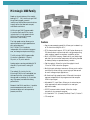
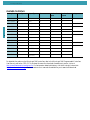
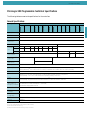
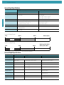
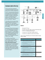
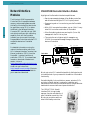
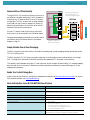
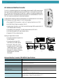
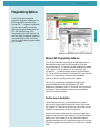
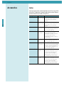
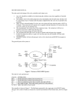
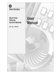
Table of Contents
Table of Contents
Refer to the MicroLogix Selector Guide
on the back cover of this publication for
assistance in selecting the correct
MicroLogix Programmable Controller for
your application.
Inside…
Page
MicroLogix 1000 Family ............................................ 5
Communication Choices.......................................... 11
Network Interface Modules.................................... 12
Programming Options.............................................. 15
4
Programming Instructions ....................................... 17
Operator Interface Devices ..................................... 19
Accessories ............................................................. 20
User Documentation ............................................... 21
Wiring Diagrams ..................................................... 22
Dimensions.............................................................. 27
MicroLogix 1000 Family
MicroLogix 1000 Family
Based on the architecture of the marketleading SLC™ 500, the MicroLogix 1000
brings blazing speed, powerful
instructions, and flexible communications
to applications that demand compact,
cost-effective solutions.
All MicroLogix 1000 Programmable
Controllers that have 24V dc inputs
include a built-in high-speed counter
(6.6k Hz) that is one of the most
functional in the industry.
The high-speed counter allows you to
capture pulses from high-speed devices
such as encoders and
PHOTOSWITCH® products,
independent of the controller’s program
scan, and energize outputs accordingly.
5
Features
• Peer-to-peer messaging capability. Allows you to network up
to 32 controllers using the AIC+.
• RTU slave protocol support. DF1 Half-Duplex allows up to
254 slave nodes to communicate with a single master using
radio modems, leased-line modems, or satellite uplinks.
The MicroLogix 1000 Programmable
Controller is available in 10-point,
16-point, or 32-point versions.
• Built-in EEPROM memory. Retains all of your ladder logic
and data if your controller loses power, eliminating the need
for battery backup or separate memory module.
Analog versions are also available with 20
discrete I/O points and 5 analog I/O
points.
• Fast throughput. Allows for typical throughput time of
1.5 ms for a 500-instruction program.
The analog I/O circuitry for the
MicroLogix 1000 units is embedded into
the base controller, not accomplished
through add-on modules. So, it provides
very high-speed, cost-effective analog
performance.
Because it has 16-bit resolution, it enables
precise measurement and control of
process variables, such as temperature,
pressure, and flow.
• Multiple input and output commons. Allows you to use the
controller for either sinking or sourcing input devices and
for multi-voltage output applications.
• Bi-directional high-speed counter. Offers real-time output
response independent of the program scan that accepts a
6.6kHz input signal.
• Adjustable DC input filters. Allows you to customize your
input response time and noise rejection to meet your
application needs.
• RS-232 communication channel. Allows for simple
connectivity to a personal computer.
• UL listed and C-UL (Canada) Certified, Class 1, Division 2
• CE compliant
MicroLogix 1000 Family
Available Controllers
6
Catalog Number Input Type
Output Type
Power
Number of
Inputs
Number of
Outputs
Analog
1761-L16AWA
AC
Relay
AC
10
6
n/a
1761-L32AWA
AC
Relay
AC
20
12
1761-L20AWA-5A AC
Relay/Analog
AC
12
8
4 inputs, 1 output
1761-L10BWA
DC
Relay
AC
6
4
n/a
1761-L16BWA
DC
Relay
AC
10
6
1761-L20BWA-5A DC
Relay/Analog
AC
12
8
4 inputs, 1 output
1761-L32BWA
DC
Relay
AC
20
12
n/a
1761-L10BWB
DC
Relay
DC
6
4
1761-L16BWB
DC
Relay
DC
10
6
1761-L20BWB-5A DC
Relay/Analog
DC
12
8
4 inputs, 1 output
1761-L32BWB
DC
Relay
DC
20
12
n/a
1761-L16BBB
DC
MOSFET/Relay(1)
DC
10
6
1761-L32BBB
DC
MOSFET/Relay(1)
DC
20
12
1761-L32AAA
AC
Triac/Relay(1)
AC
20
12
(1) Two isolated relays per unit.
For detailed information on the MicroLogix 1000 controllers, refer to the MicroLogix 1000 Programmable Controllers
User Manual, publication 1761-6.3. To purchase this manual or download a free electronic version, visit us at
http://www.theautomation bookstore.com. For fast access to related publications, visit the MicroLogix Internet site
http://www.ab.com/micrologix. Electronic versions of our manuals are available for you to search and download.
MicroLogix 1000 Family
MicroLogix 1000 Programmable Controllers Specifications
The following tables summarize the specifications for the controllers.
General Specifications
32BBB
32BWB
20BWB-5A
16BWB
10BWB
16BBB
32AAA
32BWA
20BWA-5A
16BWA
10BWA
32AWA
20AWA-5A
Specification: 1761-L
16AWA
Description:
Memory Size and Type 1 K EEPROM (approximately 737 instruction words: 437 data words)
Data Elements
512 internal bits, 40 timers, 32 counters, 16 control files, 105 integer files, 33 diagnostic status
Throughput
1.5 ms (for a 500-instruction program)(1)
Programming
Instructions
69 total (12 basic logic, 43 applied control, 14 advanced application-specific)
Power Supply Voltage 85-264V ac, 47-63 Hz
Power
120V ac
Consump240V ac
tion
24V dc
7
20.4 - 26.4V dc
15 VA 20 VA
19 VA 24 VA 26 VA 30 VA
29 VA 16 VA Not Applicable
21 VA 27 VA
25 VA 32 VA 33 VA 36 VA
36 VA 22 VA
Not Applicable
5W
10W
Power Supply Max
Inrush Current
30A for 8 ms
30A for 4 ms
50A for 4 30A for 4 ms
ms
24V dc Sensor Power
(V dc at mA)
Not Applicable
Max Capacitive Load
(User 24V dc)
200 mA
7W
Not Applicable
200 µF
Power Cycles
50,000 minimum
Operating Temp.
Horizontal mounting: 0°C to +55°C (+32°F to +131°F) for horizontal mounting
Vertical mounting(2): 0°C to +45°C (+32°F to +113°F) for discrete; 0°C to +40°C (+32°F to +113°F) for analog
Operating Humidity
5 to 95% noncondensing
Vibration
Operating: 5 Hz to 2k Hz, 0.381 mm (0.015 in.) peak to peak/2.5g panel mounted(3),1hr per axis
Non-Operating: 5 Hz to 2k Hz, 0.762 mm (0.030 (in.)peak to peak/5g, 1hr per axis
Shock
Operating: 10g peak acceleration (7.5g DIN rail mounted)(4) (11±1 ms duration) 3 times each direction, each axis
Non-Operating: 20g peak acceleration (11±1 ms duration), 3 times each direction, each axis
Agency Certification
(when product or
packaging is marked)
C-UL Class 1, Division 2, Groups A, B, C, D certified
UL listed (Class 1, Division 2 Groups A, B, C, D certified)
CE marked for all applicable directives
Terminal Screw Torque 0.9 N-m maximum (8.0 in.-lbs)
Electrostatic
Discharge
IEC801-2 at 8K V
Radiated
Susceptibility
IEC801-3 at 10 V/m, 27 MHz - 1000 MHz, 3V/m, 87 MHz - 108 MHz, 174 MHz - 230 MHz, and 470 MHz - 790 MHz
Fast Transient
IEC801-4 at 2K Power Supply, I/O; 1K V Comms
Isolation
1500V ac
(1)
(2)
(3)
(4)
A typical program contains 360 contacts, 125 coils, 7 timers, 3 counters, and 5 comparison instructions.
DC input voltage derated linearly from 30°C (30V to 26.4V).
DIN rail mounted controller is 1g.
Relays are derated an additional 2.5g on 32 pt. controllers.
MicroLogix 1000 Family
General Input Specifications
Description
8
Specification
100-120V ac Controllers
24V dc Controllers
Voltage Range
79 to 132V ac, 47 to 62 Hz
14 to 30V dc
On Voltage
79V ac min.
132V ac max.
14V dc min.
24V dc nominal
26.4V dc max. at +55°C (+131°F)
30.0V dc max. at +30°C (+86°F)
Off Voltage
20V ac
5V dc
On Current
5.0 mA min. at 79V ac 47 Hz
12.0 mA nominal at 120V ac 60 Hz
16.0 mA max. at 132V ac 63 Hz
2.5 mA min. at 14V dc
8.0 mA nominal at 24V dc
12.0 mA max. at 30V dc
Off Current
2.5 mA max.
1.5 mA max.
Nominal Impedance
12K ohms at 50 Hz
10K ohms at 60 Hz
3K ohms
Inrush Maximum
250 mA max.(1)
Not Applicable
(1) To reduce the inrush maximum to 35 mA, apply a 6.8K ohm, 5W resistor in series with the input. The on-state voltage increases to 92V ac as a result.
Input ac Voltage Range
0V ac
20V ac
79V ac
132V ac (max.)
On State
Off State
Input State Not Guaranteed
Input dc Voltage Range
0V dc
5V dc
14V dc
26.4V dc @ 55°C (131°F)
30V dc @ 30°C (86°F)
On State
Off State
Input State Not Guaranteed
General Output Specifications
Description
Specifications
Type
Relay
Voltage
See wiring diagrams on page 22.
MOSFET
Max. Load Current
Refer to the Relay Contact 1.0A per point at +55°C (+131°F)
Rating Table.
1.5A per point at +30°C (+86°F)
Min. Load Current
10.0 mA
Triac
0.5A per point at +55°C (+131°F)
1.0A per point at +30°C (+86°F)
1 mA
10.0 mA
Current per Controller 1440 VA
3A for L16BBB
6A for L32BBB
1440 VA
Current per Common
8.0A
3A for L16BBB
6A for L32BBB
Not Applicable
Max. Off State
Leakage Current
0 mA
1 mA
2 mA at 132V ac
4.5 mA at 264V ac
Off to On Response
10 ms max.
0.1 ms
8.8 ms at 60 Hz
10.6 ms at 50 Hz
On to Off Response
10 ms max.
1 ms
11.0 ms
Surge Current per
Point
Not Applicable
4A for 10 ms(1)
10A for 25 ms(1)
(1) Repeatability is once every 2 seconds at +55°C (+131°F).
MicroLogix 1000 Family
Analog Input Specifications
The two voltage inputs accept ±10.5V dc. The two current inputs accept ±21 mA.
Description
Specification
Voltage Input Range
-10.5 to +10.5V dc - 1LSB
Current Input Range
-21 to +21 mA - 1LSB
Type of Data
16-bit signed integer
Input Coding -21 to +21 mA - 1LSB, -10.5 to +10.5V dc - 1LSB
-32,768 to +32,767
Voltage Input Impedance
210K Ω
Current Input Impedance
160 Ω
Input Resolution(1)
16 bit
Non-linearity
< 0.002%
Overall Accuracy 0°C to +55°C
±0.7% of full scale
Overall Accuracy Drift 0°C to +55°C (max.)
±0.176%
Overall Accuracy at +25°C (+77°F) (max.)
±0.525%
Voltage Input Overvoltage Protection
24V dc
Current Input Overcurrent Protection
±50 mA
Input to Output Isolation
30V rated working/500V test 60 Hz/1s
Field Wiring to Logic Isolation
(1) The analog input update rate and input resolution are a function of the input filter selection.
Analog Output Specifications
The analog output can be configured for either voltage (0V dc to +10V dc) or current (+4 to +20 mA).
Description
Specification
Voltage Output Range
0 to 10V dc -1LSB
Current Output Range
4 to 20 mA - 1LSB
Type of Data
16-bit signed integer
Non-linearity
0.02%
Step Response
2.5 ms (at 95%)
Load Range - Voltage Output
1K Ω to ∞ Ω
Load Range - Current Output
0 to 500 Ω
Output Coding 4 to 20 mA - 1 LSB, 0 to 10Vdc - 1LSB
0 to 32,767
Voltage Output Miswiring
can withstand short circuit
Current Output Miswiring
can withstand short circuit
Output Resolution
15 bit
Analog Output Settling Time
3 msec (maximum)
Overall Accuracy 0°C to +55°C
±1.0% of full scale
Overall Accuracy Drift 0°C to +55°C (max.)
±0.28%
Overall Accuracy at +25°C (+77°F) (max.) - Current Output
0.2%
Field Wiring to Logic Isolation
30V rated working/500V isolation
9
MicroLogix 1000 Family
Relay Contact Rating Table (applies to all Bulletin 1761 controllers)
Maximum Volts
Amperes
Amperes Continuous
Voltamperes
Make
Break
240V ac
7.5A
0.75A
120V ac
15A
1.5A
125V dc
0.22A(1)
1.0A
28 VA
24V dc
1.2A(1)
2.0A
28 VA
2.5A
Make
Break
1800 VA
180 VA
(1) For dc voltage applications, the make/break ampere rating for relay contacts can be determined by dividing 28 VA by the applied dc voltage. For example,
28 VA/48V dc = 0.58A. For dc voltage applications less than 48V, the make/break ratings for relay contacts cannot exceed 2A. For dc voltage applications greater than 48V, the
make/break ratings for relay contacts cannot exceed 1A.
10
Input Filter Response Times (Discrete)
The input filter response time is the time from when the external input voltage reaches an on or off state to when the micro
controller recognizes that change of state. All controllers with dc inputs have configurable input filter response times.
The higher you set the response time, the longer it takes for the input state change to reach the micro controller. However,
setting higher response times also provides better filtering of high frequency noise.
You can apply a unique input filter setting to each of the three input groups:
• 0 and 1 (30 Hz to 6.6 kHz)
• 2 and 3 (30 Hz to 6.6 kHz)
• 4 to x (30 Hz to 1.0 kHz) (x equals 9 for 16 I/O controllers; x equals 19 for 32 I/O controllers)
High-Speed Counter
The MicroLogix 1000 high-speed counter has advanced high-speed capabilities that minimize scan time no matter how
complex the program. All MicroLogix 1000 controllers that have 24V dc inputs include a built-in high-speed counter that
is one of the most functional in the industry.
Features
• High-count frequency of 6.6 kHz
• Two operating modes: up count and bi-directional
• Fast Hold and Reset inputs available in either mode to enhance throughput
• True interrupt capabilities
The high-speed counter allows you to capture pulses from high-speed devices such as encoder and PHOTOSWITCH®
products, independent of the controller’s program scan, and energize outputs accordingly.
For detailed information on the MicroLogix 1000 high-speed counter, refer to the MicroLogix 1000 Programmable
Controllers User Manual, publication 1761-6.3. To purchase this manual or download a free electronic version, visit us at
http://www.theautomation bookstore.com. For fast access to related publications, visit the MicroLogix Internet site http://
www.ab.com/micrologix. Electronic versions of our manuals are available for you to search and download.
Communication Choices
Communication Choices
All MicroLogix 1000 programmable
controllers provide several communication
options to fit into a variety of applications.
The DF1 Full-Duplex protocol allows the
MicroLogix 1000 to communicate directly
with another device, such as a personal
computer or an operator interface device.
The DF1 Full-Duplex protocol (also
referred to as DF1 point-to-point
protocol) is useful where RS-232 point-topoint communication is required.
The DH485 multi-drop communication
capability allows you to network up to 32
MicroLogix or SLC 500 controllers,
Human/Machine Interface (HMI) devices
and/or personal computers using peer-topeer messaging.
MicroLogix 1000 controllers also support
DF1 Half-Duplex Slave communications
for use in SCADA systems as a Remote
terminal Unit (RTU). This open network
protocol enables MicroLogix controllers to
communicate as responder (slave) nodes
on DF1 master/slave networks that
support up to 254 responder devices with
a single initiator (master).
And, the MicroLogix 1000 can
communicate on a DeviceNet network as
well. DeviceNet digitally links push
buttons, sensors, actuators, PLCs and
other industrial devices on an open
network. MicroLogix controllers on
DeviceNet allow you to take advantage of
the latest advances in communications.
DeviceNet uses “producer/consumer”
technology, a networking technology that
significantly reduces the amount of traffic
on the network, thus improving efficiency
and data throughput.
WorkStation
MicroLogix
1200
SLC
Controller
MicroLogix
1000
DC
Drive
MicroLogix
1200
MicroLogix
1500
Filter
SCADA Master
Flex I/O
Radio/Phone Modem
MicroLogix
1500
MicroLogix
1200
MicroLogix
1000
11
Variable
Frequency Drive
System
Reliance AC Motor
Features:
• Standard RS-232 port
• 300; 600; 1200; 4800; 9600; 19,200 and 38,400 baud rates
• RTS/CTS Hardware handshake signals
• Connection to DH485 and DeviceNet networks
• Connection to modems for remote communications
The MicroLogix 1000 allows you to choose the network that best
meets your needs.
If your application requires:
• Connections of low-level devices directly to
plant floor controllers, without the need to
interface them through I/O modules
• More diagnostics for improved data collection
and fault detection
• Less wiring and reduced start-up time than
traditional, hard wired systems
Use this network
DeviceNet via the
1761-NET-DNI
DH485 via the
• Plant-wide and cell-level data sharing with
program maintenance
1761-NET-AIC
• Data sharing between controllers
• Program upload, download, and monitoring to all
controllers from one location
• Compatibility with multiple Allen-Bradley HMI
devices
• Connection to dial-up modems for remote
program maintenance or data collection
• Connection to leased-line or radio modems for
use in SCADA systems
• Remote Terminal Unit (RTU) functions
DF1 Full-Duplex
DF1 Half-Duplex
Slave
Network Interface Modules
Network Interface
Modules
12
1761-NET-DNI DeviceNet Interface Module
Highlights of the DeviceNet Interface’s capabilities are:
• Peer-to-peer messaging between Allen-Bradley controllers
and other devices using the DF1 Full-Duplex protocol
The Micrologix 1000 Programmable
Controllers’ list of impressive hardware,
memory, and processing features makes
this family of controllers the ideal choice
for applications using 32 I/O or below.
Additionally, the Advanced Interface
Converter (AIC+) and MicroLogix 1000
controllers provide you with networking
capability. And, with the DeviceNet
Interface, you can connect MicroLogix
Programmable Controllers and other DF1
compatible devices to a DeviceNet
network.
• Programming and on-line monitoring over the DeviceNet
network
• With a DNI connected to a modem, you can “dial in” to any
other DNI-controller combination on DeviceNet
• Other DeviceNet products can send explicit (Get or Set)
messages with the DNI at any time
• The controller can initiate an explicit message to any
UCMM (Unconnected Message Manager) compatible
device on DeviceNet
DNI
For detailed information on using the
network interface modules, refer to the
AIC+ Advanced Interface Converter User
Manual, publication 1761-6.4, and the
DeviceNet™ Interface User Manual,
publication 1761-6.5. To purchase these
manuals or download a free electronic
version, visit us at
http://www.theautomationbookstore.com.
For fast access to related publications, visit
the MicroLogix Internet site
http://www.ab.com/micrologix. Electronic
versions of our manuals are available for
you to search and download.
SLC 5/03
DANGER
DNI
MicroLogix
1000
SLC 5/03
DANGER
Master
DeviceNet
DANGER
DNI
DNI
DANGER
MicroLogix
1200
DNI
DNI
DANGER
DANGER
MicroLogix
1500
Personal
Computer
MicroLogix micro-PLCs extend the benefits of distributed control
to the device level of your process with the addition of DeviceNet
functionality.
DeviceNet digitally links push buttons, sensors, actuators, PLCs
and other industrial devices. It reduces the installation and
maintenance costs of multiple discrete wires with a single cable that
handles both communications and power distribution.
The 1761-NET-DNI Series B
Interface (DNI) brings the fast
response, low cost and reliability of
open DeviceNet connectivity to all
MicroLogix controllers and most
other Allen-Bradley controllers.
Network Interface Modules
Advanced Slave I/O Functionality
Inputs
Outputs
Through the DNI, MicroLogix controllers can function as
cost-effective DeviceNet slave nodes. The DNI presents to
DeviceNet up to 32 words of data (16 inputs, 16 outputs,
configurable). The DNI can either poll or accept data sent
from the MicroLogix to keep its mapped I/O data up-todate with the actual data in the controller, while the DNI
handles all DeviceNet communications.
Status
Timers
DNI Data
DeviceNet Outputs
Explicit Data
1
2
3
4
to
16
64 words max.
Split point
adjustable
Master’s Inputs
Split point
adjustable
Explicit Data
0
1
2
3
to
40
64 words max.
DeviceNet Inputs
All local I/O remains under the MicroLogix controllers’
direct control, yet can be visible to the DeviceNet master.
DeviceNet Network
Master’s Outputs 0
Counters
Integers
Using standard messaging commands, you can easily read or
write data to other controllers as shown in the network
diagram on page 12.
Mapping of integer blocks to
DNI I/O words done with
DeviceNet Manager software
Mapping of integer files
performed in ladder logic
Simple, Reliable Peer-to-Peer Messaging
The DNI brings brand-new functionality to DeviceNet by enabling peer-to-peer messaging between devices that use the
DF1 Full-Duplex protocol.
The DNI takes the DF1 Full-Duplex commands, wraps them in the DeviceNet protocol and sends them to the target
DNI. The target DNI removes the DeviceNet information and passes the DF1 command to the end device.
This capability works between controllers, PCs and controllers, and for program up/downloading. I/O and data messages
are prioritized, which minimizes I/O determinism problems typically encountered on networks that support I/O and
messaging simultaneously.
Enable Your Control Strategy Now
Helpful information and free DNI configuration software are also available at http://www.ab.com/micrologix. For more on
the DeviceNet standard, visit http://www.odva.org.
DeviceNet Interface Series B (1761-NET-DNI) Specifications
Description
Specifications
24V dc Power Source Requirements
11 to 25V dc
Current Draw
200 to 250 mA
400 mA maximum inrush current (30 msec, max.)
Internal Isolation
500V dc
Operating Ambient Temperature
0 to +60°C (+32 to +140°F)
Storage Temperature
-40 to +85°C (-40 to +175°F)
Agency Certification
DeviceNet
•
•
•
•
•
UL 1604
C-UL C22.2 No. 213
Class 1, Division 2, Groups A, B, C, D
CE compliant for all applicable directives
ODVA conformance 2.0-A12
maximum number of nodes = 64
maximum length = 500m at 125 kbaud or 100m at 500 kbaud
13
Network Interface Modules
AIC+ Advanced Interface Converter
The AIC+ is a networking device from Allen-Bradley that provides DH485 network access
from any DH485 compatible device that has a RS-232 port, including MicroLogix 1000,
SLC 5/03 and 5/04, and PanelView 550 and 900. In addition, the device provides isolation
between all ports for a more stable network and protection of connected devices. The unit is
DIN rail or panel mountable and is industrially hardened.
The Advanced Interface Converter provides a simple, cost- effective solution for connecting
RS-232 devices to a DH485 network. The AIC+ also provides:
• Two isolated RS-232 connections - one 9-pin D-shell and one 8-pin mini DIN
14
• An RS-485 6-pin Phoenix connection (Port 3)
• Accepts power via the 8-pin mini DIN from the MicroLogix 1000 controller (Port 2)
or an external power connection.
• Compatibility with existing SLC DH485 networks that use 1747-AICs
• Auto baud rate capability for ease of system set-up
• Diagnostic LEDs for network activity
Some typical applications include:
AIC+
AIC+
• Connecting a personal computer to a
DH485 network
TERM
TERM
A
B
COM
COM
SHLD
SHLD
CHS GND
TX
TX
TX
PWR
PWR
DC SOURCE
CABLE
EXTERNAL
SLC 5/04
DH485 Network
AIC+
AIC+
TERM
TX
PWR
DC SOURCE
CABLE
EXTERNAL
MicroLogix
1000
TX
TX
COM
SHLD
CHS GND
TX
B
COM
SHLD
CHS GND
A
B
COM
SHLD
TERM
A
B
COM
Description
Specifications
24V dc Power Source Requirement
20.4 - 28.8V dc
Current Draw
120 mA
200 mA maximum inrush current
Internal Isolation
500V dc
Operating Ambient Temperature
0 to +60°C (+32 to +140°F)
Storage Temperature
-40 to +85°C (-40 to +175°F)
AIC+
TERM
A
B
PanelView 550
AIC+
TERM
A
TX
EXTERNAL
SHLD
CHS GND
TX
PWR
DC SOURCE
CABLE
EXTERNAL
MicroLogix
1200
TX
TX
CHS GND
TX
TX
PWR
TX
DC SOURCE
TX
PWR
DC SOURCE
CABLE
CABLE
EXTERNAL
EXTERNAL
MicroLogix
1500
Advanced Interface Converter (1761-NET-AIC) Specifications
DH485, DF1, or “user” Network
TX
TX
CABLE
• Linking SLC 5/03 or SLC 5/04
processors using DF1 Half-Duplex
“master/slave” protocol. This allows
you to connect remote “islands” of
automation to a master controller to
upload diagnostic and status
information.
PanelView
CHS GND
TX
DC SOURCE
• Connecting MicroLogix 1000
controllers to a DH485 network
Agency Certification
A-B
A
B
• UL 508
• CSA C22.2
• CE compliant for all applicable directives
maximum number of nodes = 32 per multidrop network
maximum length = 1,219m (4,000 ft.) per multidrop network
maximum number of “ganged” multidrop networks = 2
Personal
Computer
Programming Options
Programming Options
The following sections describe
programming options available for the
MicroLogix 1000 controllers. With
RSLogix 500™ Programming Software,
you can create, modify, and monitor
application programs used by both the
SLC 500 and MicroLogix 1000
Programmable Controller families. Use
the Hand-Held Programmer to perform
all programming functions including
monitoring application programs used by
your controller.
15
RSLogix 500 Programming Software
The RSLogix 500 ladder logic programming package helps you
maximize performance, save project development time, and
improve productivity. This product has been developed to operate
on Microsoft’s 32-bit, Windows® 95, Windows® 98, and
Windows NT™ operating systems. Supporting Allen-Bradley’s
SLC 500 and MicroLogix families of processors, RSLogix 500 was
the first PLC programming software to offer unbeatable
productivity with an industry-leading user interface.
RSLogix 500 programming packages are compatible with
programs created with Rockwell Software’s DOS-based
programming packages for the SLC 500 and MicroLogix families
of processors, making program maintenance across hardware
platforms convenient and easy.
Flexible, Easy-to-Use Editors
Flexible program editors let you create application programs
without worrying about getting the syntax correct as you create
your program. A Project Verifier builds a list of errors that you can
navigate to make corrections at your convenience.
Powerful online editing features let you modify your application
program while the process is still operating. The Test Edits feature
allows you to test the operation of your modification before it
becomes a permanent part of the application program. Online and
offline editing sessions are limited only by the amount of available
RAM.
Programming Options
Projects developed with Rockwell Software’s DOS programming packages, SLC 500 and MicroLogix A.I. Series, APS and
MPS, can be moved to the RSLogix environment simply by opening the existing project with the appropriate RSLogix
package.
Drag-and-drop editing lets you quickly move or copy instructions from rung to rung within a project, rungs from one
subroutine or project to another, or data table elements from one data file to another.
Context menus for common software tools are quickly accessible by clicking the right mouse button on addresses, symbols,
instructions, rungs, or other application objects. This convenience provides you with all the necessary functionality to
accomplish a task within a single menu.
Point-and-Click I/O Configuration
16
The easy-to-use I/O Configurator lets you click or drag-and-drop a module from an all-inclusive list to assign it a slot in
your configuration. Advanced configuration, required for specialty and analog modules, is easily accessible. Convenient
forms speed entry of configuration data. An I/O auto configuration feature is also available.
Powerful Database Editor
Use the Symbol Group Editor to build and classify groups of symbols so that you can easily select portions of your recorded
documentation to be used from project to project.
Use the Symbol Picker list to easily address instructions in your ladder logic by clicking addresses or symbols to assign them
to your ladder instructions.
Diagnostics and Troubleshooting Tools
Simultaneously examine the status of bits, timers, counters, inputs, and outputs all in one window with the Custom Data
Monitor. Each application project you create can have its own Custom Data Monitor window.
Easily review status bit settings specific to your application programming including Scan Time information, Math Register
information, Interrupt settings and more with the tabbed Status displays.
Selection Chart
Catalog Number
9324-RL0300ENE
(1) (2)
Description
RSLogix 500 Programming for the SLC 500 and MicroLogix Families on CD-ROM. Includes RSLinx Lite.
9324-RL0100ENE(1) (2)
RSLogix 500 Starter Programming for the SLC 500 and MicroLogix Families on CD-ROM. This package is a functionally
limited version of RSLogix 500.
Programming Cables
See page 20 for information on MicroLogix 1000 programming cables.
(1) To use RSLogix 500 programming software, your system must be a Pentium 100 MHz or higher, Windows® 95, Windows® 98, or Windows NT™.
(2) Also available in Spanish, German, French, Italian, and Portuguese.
MicroLogix 1000 Hand-Held Programmer
The MicroLogix 1000 Hand-Held Programmer (HHP) allows you to create, edit, monitor, and
troubleshoot Instruction List (Boolean) programs for your micro controller. With the HHP and
either a 10-, 16-, or 32-I/O point or analog micro controller, you eliminate the need for hard-wired
relay logic. This device also allows you to transfer programs to and from an optional removable
memory module.
Programming Instructions
Programming
Instructions
MicroLogix has the range of functionality
necessary to address diverse applications,
with 12 basic logic instructions, 43
applied control instructions, and 14
advanced application-specific instructions.
Your controller uses the following types of
instructions:
• Basic Instructions
Basic Instructions
These instructions represent hardwired logic circuits used for the
control of a machine.
Count Up/Count Down
Examine if Closed
Examine if Open
One Shot Rising
Output Energize
Output Latch/Output Unlatch
Reset
Retentive On-delay Timer
Timer On/Timer Off-Delay
• Comparison Instructions
• Data Instructions
• Communications Instructions
• Math Instructions
• Program Flow Control Instructions
• Application Specific Instructions
• High-Speed Counter Instruction
Comparison Instructions
These instructions are used to test pairs of values to condition the
logical continuity of a rung.
Equal
Greater Than
Greater Than or Equal
Less Than
Less Than or Equal
Limit Test
Masked Comparison for Equal
Not Equal
Data Handling Instructions
These instructions convert information, manipulate data in the
controller, and perform logic operations.
And
Convert to BCD
Convert from BCD
Copy File
Decode
Encode
Exclusive Or
Fill File
Load/Unload First In Last Out
Load/Unload Last In First Out
Masked Move
Move
Negate
Not
Or
17
Programming Instructions
Communications Instructions
Application Specific Instructions
This instruction allows data to be read/written to other
devices.
These instructions allow you to use a single instruction or
pair of instructions to perform common complex
operations.
Message
Bit Shift Right/Bit Shift Left
Math Instructions
These instructions take two input values, perform the
specified arithmetic functions, and output the result to an
assigned memory location.
18
Interrupt Subroutine
Selectable Timer Interrupt Enable/Disable
Selectable Timer Interrupt Start
Sequencer Output/Sequencer Compare
Add/Subtract
Multiply/Divide
Clear
Double Divide
High-Speed Counter Instructions
These instructions configure, control, and monitor the
controller’s hardware counter.
Scale Data
High-Speed Counter
Square Root
High-Speed Counter Enable/Disable
High-Speed Counter Load
Program Flow Control Instructions
These instructions control the sequence in which your
program is executed.
High-Speed Counter Reset
High-Speed Counter Reset Accumulator
Update High-Speed Counter Image Accumulator
Label
Immediate Input with Mask
Immediate Output with Mask
Jump
Jump to Subroutine
Master Control Reset
Subroutine
Suspend
Temporary End
For detailed information on the MicroLogix 1000 programming instructions, refer to the MicroLogix 1000 Programmable
Controllers User Manual, publication 1761-6.3. To purchase this manual or download a free electronic version, visit us at
http://www.theautomation bookstore.com. For fast access to related publications, visit the MicroLogix Internet site
http://www.ab.com/micrologix. Electronic versions of our manuals are available for you to search and download.
Operator Interface Devices
Operator Interface
Devices
Operator interface devices provide you
with powerful plant floor control and data
monitoring capabilities.
MicroView™ Operator
Interface
The MicroView Operator Interface is a
feature-packed, cost effective operator
interface designed for data monitoring,
data display, and data entry. This device
features a 2-line x 16-character display
window.
19
DTAM™ Micro Operator Interface
The DTAM Micro Operator interface provides another operator
interface to the MicroLogix line. DTAM Micro is a low-cost
operator interface. This device features a 2-line x 20-character
display window. Up to 244
application screens can be stored
in memory.
DTAM™ Plus Operator
Interface
The DTAM Plus Operator
Interface provides a highly functional operator interface for the
MicroLogix 1000 family of processors. This device features a 4-line
x 20-character display window for viewing data table information
and operator prompts. Display screens are created using an Offline
Development software Package.
PanelView™ Operator Terminals
PanelView Operator Terminals
provide operator interface
capabilities in space saving, flat
panel designs or 14-inch CRTs.
These electronic operator
interfaces feature pixel graphics
and high performance
functionality in color and
monochrome flat panel
displays, as well as Super VGA
CRTs with optimum viewing angles and resolution. PanelView
terminals provide extensive diagnostic information to operators
during fault conditions through message windows, alarm windows,
and simple graphics.
Accessories
Accessories
Cables
Use the communication cables listed below with MicroLogix 1000
controllers. Cables come in several lengths and connector styles to
provide connectivity to the MicroLogix line.
Catalog Number
Cable Type
1761-CBL-AC00
9-pin D-shell This 45 cm (17.7 in.) cable is used to
to 9-pin D-shell connect port 1 of the 1761-NET-AIC to
the 9-Pin DTE port of a personal
computer.
1747-CP3
9-pin D-shell This 3m (9.8 ft) cable is used to
to 9-pin D-shell connect port 1 of the 1761-NET-AIC to
the 9-Pin DTE port of a personal
computer.
1761-CBL-AM00
8-pin DIN
to 8-pin DIN
This 45 cm (17.7 in.) cable is used to
connect the MicroLogix controller to
port 2 of the 1761-NET-AIC
1761-CBL-HM02
8-pin DIN
to 8-pin DIN
This 2m (6.56 ft) cable is used to
connect the MicroLogix 1000
Programmable Controller to the HHP
or to connect any MicroLogix
Programmable Controller to port 2 of
the 1761-NET-AIC
1761-CBL-AP00
9-pin D-shell
to 8-pin DIN
This 45 cm (17.7 in.) cable is used to
connect a MicroLogix controller to
port 1 of the 1761-NET-AIC.
1761-CBL-PM02
9-pin D-shell
to 8-pin DIN
This 2m (6.56 ft) cable is used to
connect the MicroLogix Programmable
Controller to an IBM compatible PC or
to connect an IBM compatible PC to
port 2 of the 1761-NET-AIC
1761-CBL-AS03
6-pin phoenix
to RJ45
This 3m (9.8 ft) cable is used to
connect the SLC 500 fixed, SLC 5/01,
SLC 5/02, and SLC 5/03 processor
RJ45 port to the 6-Pin Phoenix
Connector (port 3) of the 1761-NETAIC Advanced Interface Converter.
1761-CBL-AS09
6-pin phoenix
to RJ45
This 3m (9.8 ft) cable is used to
connect the SLC 500 fixed, SLC 5/01,
SLC 5/02, and SLC 5/03 processor
RJ45 port to the 6-Pin Phoenix
Connector (port 3) of the 1761-NETAIC Advanced Interface Converter.
20
Description
User Documentation
User Documentation
For an introduction to micro PLC’s refer to the MicroMentor™,
publication 1761-MMB. The MicroMentor book includes
illustrations, sample applications you can put to immediate use,
step-by-step strategies, and worksheets.
Additionally, MicroLogix 1000 user documentation presents
information according to the tasks you perform and the
programming environment you use. Refer to the table below for
information on MicroLogix 1000 publications.
Title
Publication
Number
MicroLogix™ 1000 Programmable Controllers
Installation Instructions
1761-5.1.2
AIC+ Advanced Interface Converter and DeviceNet™
Interface Installation instructions
1761-5.11
MicroLogix™ 1000 Programmable Controllers User
Manual
1761-6.3
MicroLogix™ 1000 with Hand-Held Programmer (HHP)
User Manual
1761-6.2
AIC+ Advanced Interface Converter User Manual
1761-6.4
DeviceNet™ Interface User Manual
1761-6.5
DTAM™ Micro Operator Interface Module User Manual
2707-803
MicroView™ Operator Interface Module User Manual
DataDisc™ CD-ROM Information Library
2707-805
1795-CDRS and
1795-CDRL
For assistance selecting the correct MicroLogix Programmable
Controller for your application, see the MicroLogix selector guide
on the back of this publication. If you would like a system overview
for the MicroLogix 1200 or MicroLogix 1500 controllers, refer to
the following table.
See this Document
Publication
Number
MicroLogix™ 1200 System Overview
1762-SO001A-US-P
MicroLogix™ 1500 System Overview
1764-SO001A-US-P
To purchase a manual or download a free electronic version, visit us
at http://www.theautomation bookstore.com. For fast access to
Bulletin 1761, 1762, and 1764 publications, visit the MicroLogix
Internet site http://www.ab.com/micrologix. Electronic versions of
our manuals are available for you to search and download.
21
Wiring Diagrams
Wiring Diagrams
Sinking and Sourcing
The following pages show the MicroLogix
1000 wiring diagrams.
Any of the controllers with dc inputs can be wired as either sinking
or sourcing configurations depending on how the DC COM is
wired.
Sinking and Sourcing Wiring Examples
Note that the 1761-L32BWA wiring diagrams below also apply to
1761-L10BWA, -L10BWB, -L16BWA, -L16BWB, -L16BBB,
-L20BWA-5A, -L20BWB-5A, -L32BWB, -L32BBB.
22
1761-L32BWA
Surge Suppression
We recommend surge suppressors across all inductive outputs.
+dc or L1
VAC/VDC
OUT 0
OUT 1
OUT 2
ac or dc
Outputs
Snubber
OUT 3
OUT 4
OUT 5
OUT 6
OUT 7
COM
dc COM or L2
By adding a suppression device directly across the coil of an
inductive device, you will reduce the effects of voltage transients
caused by interrupting the current to that inductive device, and
will prevent electrical noise from radiating into system wiring.
For more detailed surge suppression information, as well as a listing
of recommended Allen-Bradley surge suppressors, see the
MicroLogix 1000 Programmable Controllers User Manual,
publication 1761-6.3.
Wiring Diagrams
MicroLogix 1000 Wiring Diagrams
IMPORTANT
This symbol denotes a functional earth ground
terminal which provides a low impedance path
between electrical circuits and earth for non-safety purposes,
such as noise immunity improvement.
1761-L10BWA (Sinking Input Configuration)
1761-L10BWB (Sinking Input Configuration)
23
1761-L16AWA Wiring Diagram
1761-L16BWA (Sinking Input Configuration)
Wiring Diagrams
1761-L16BWB (Sinking Input Configuration)
1761-L16BBB (Sinking Input Configuration)
24
1761-L32AAA
1761-L32AWA
Wiring Diagrams
1761-L32BWA (Sinking Input Configuration)
1761-L32BWB (Sinking Input Configuration)
25
1761-L32BBB (Sinking Input Configuration)
Wiring Diagrams
1761-L20AWA-5A
26
1761-L20BWA-5A (Sinking Input Configuration)
1761-L20BWB-5A (Sinking Input Configuration)
Dimensions
Dimensions
Dimension Drawings
Dimensions are in millimeters (inches).
1761-L10BWA, -L10BWB, -L16BWA, -L16BWB, -L16BBB
80 (3.15)
27
120
(4.72)
1761-L16AWA
80 (3.15)
133
(5.24)
1761-L20AWA, -L20BWA, -L20BWB, -L32AWA, -L32BWA,
-L32BWB, -L32AAA, -L32BBB
80 (3.15)
200
(7.87)
Dimensions
MicroLogix 1000 Hand-Held Programmer
35.0
(1.37)
94.48
(3.72)
172.21
(6.78)
28
76.45
(3.01)
1761-L10BWA, -L16AWA, ---L16BWA, -L20AWA, -L20BWA,
-L32AWA, -L32BWA, -L32AAA
25.4
(1.0)
1761-L10BWB, -L16BWB,
-L16BBB, -L20BWB,
-L32BWB, -L32BBB
-
MicroLogix 1000
DIN Rail
Dimensions
33 (1.3)
80 (3.15)
80 (3.15)
DIN
Rail
16 (.63)
73
(2.87)
40
(1.57)
84 (3.3)
Dimensions
DeviceNet Interface
(DNI)
Advanced Interface Converter
(AIC+)
52.07 mm
(2.05 in.)
52.07 mm
(2.05 in.)
107 mm
(4.20 in.)
118 mm
(4.64 in.)
6.6 mm
(0.26 in.)
27.7 mm
(1.09 in.)
Allow 15 mm (0.6 in) for DIN rail latch
movement during installation and removal.
118 mm
(4.64 in.)
107 mm
(4.20 in.)
29
27.7 mm
(1.09 in.)
64.8 mm
(2.55 in.)
Allow 15 mm (0.6 in) for DIN rail latch
movement during installation and removal.
Dimensions
Notes
30
Dimensions
31