1
C1
User’s Manual
Page 8 of 12
Potentiometers/Tuning
much derivative can cause the system to undershoot
and “creep” into the target position or become
unstable.
Integral Gain – By adjusting the integral gain, the
user can reduce the steady state error of the system.
Integral gain be increased or decreased by turning
the potentiometer clockwise or counterclockwise,
respectively. Too little integral gain can result in
steady state error while too much integral gain can
cause oscillations and overshoot.
Ramp Rate – By adjusting the ramp rate, the user can
set the ramp rate of the command input to the
controller. The ramp rate be increased or decreased
by turning the potentiometer clockwise or
counterclockwise, respectively. A high ramp rate
results in a slower rise time while a lower ramp rate
results in a faster rise time.
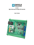
The C1 has 4 potentiometers (RP1, RP2, RP3 and RP4)
which allow the user to adjust different gains depending on
jumper configuration. For instructions on how to switch
between configurations see the Jumper Configurations
section. A polymer non-conductive screwdriver is the
preferred method for adjusting the potentiometers. Care
should be taken not to allow metal screwdrivers to touch
other components on the board.
Minimum Feedback – By adjusting minimum
feedback, the user can offset the minimum feedback
value for the controller. For feedback sensor with a
minimum output greater than 0V or 4mA, this
adjustment should be used. The minimum feedback
be increased or decreased by turning the
potentiometer clockwise or counterclockwise,
respectively. For sensors that do not require any
offset, this potentiometer should be set fully counter
clockwise.
Proportional Gain –By adjusting the proportional gain,
the user can adjust the responsiveness of the system
to changes in command or feedback.
The
responsiveness of the system can be increased or
decreased by turning the proportional gain clockwise
or counterclockwise, respectively. A gain that is too
low can result in an unresponsive system while a
gain that is too high can cause the system to
become unstable.
Derivative Gain – By adjusting the derivative gain, the
user can set the damping applied to the system. This
damping can be increased or decreased by turning
derivative gain clockwise or counterclockwise,
respectively. Damping helps reduce overshoot and
smoothes out system performance. However, too
© 2011 Enfield Technologies
As Enfield Technologies strives for continuous
improvement and dedication to product development,
specifications are subject to change
v20110311
Maximum Feedback – By adjusting maximum
feedback, the user can offset the maximum feedback
value for the controller. For feedback sensor with a
maximum output less than 10V or 20mA, this
adjustment should be used. The maximum feedback
be increased or decreased by turning the
potentiometer clockwise or counterclockwise,
respectively. For sensors that do not require any
offset, this potentiometer should be set fully
clockwise.
WARNING: Installation and operation of electronic and high pressure
systems (fluids and compressed gas) involves risk including property
damage and personal injury or death. Users should be properly
trained or certified and take safety precautions.