1
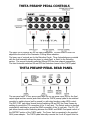
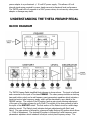
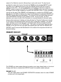
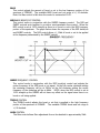
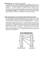
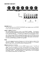
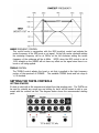
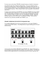
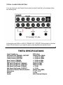
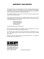
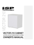
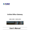
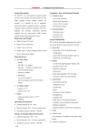
INTRODUCTION Congratulations on your purchase of the THETA Preamp Pedal. The THETA Preamp Pedal was designed to provide the maximum possible over the top performance. With a front end preamplifier, a full complement of pre and post gain tone, over the top screaming gain, more than any preamplifier or pedal available plus a full Decimator II G-String noise reduction system. The THETA Preamp Pedal can be used as a dual channel preamplifier with both a clean preamp and distortion channel or with the front end preamp overdriving the distortion for massive high gain. Both Clean and Distort sections provide noise reduction with a full implementation of Decimator II G-String noise reduction allowing the use of extremely high gain with absolutely no noise. The THETA Preamp Pedal also incorporates ISP proprietary “dynamic gain modulation” providing a dynamic feel similar to a tube amplifier with a tube rectifier. Please read this manual carefully for a through explanation of the THETA Preamp Pedal and its functions. IMPORTANT SAFTEY INSTRUCTIONS Please read the following very carefully before operating this unit Read ALL instructions carefully before using this unit. Keep these instructions for future reference. Heed all warnings and follow all instructions. Do not use this unit near water, in the rain, or where there is moisture. If this warning is ignored a serious electrical shock or death may occur. Do not attempt to service this unit. No user serviceable parts inside. Refer servicing to qualified, ISP approved personnel. Servicing is required when the unit is damaged in any way, such as power adaptor is damaged, liquid has been spilled into the unit, the unit has been exposed to rain or moisture, does not operate normally, or has been dropped. Care should be taken to avoid to spill any foreign objects or liquid into this unit. Avoid exposure of this equipment to dripping or splashing and ensure that no objects filled with liquid, such as vases, are placed on the equipment. Only use accessories or attachments that are specified by the manufacturer. Failure to follow these instructions may void the warranty. NO UER SERVICABLE PARTS INSIDE. REFER SERVICING TO QUALIFIED ISP TECHNOLOGIES SERVICE PERSONNELL. The lightning bolt triangle is used to alert the user to the risk of electric shock. The exclamation point triangle is used to alert the user to important operating or maintenance instructions. POWER REQUIREMENTS This unit requires the connection of the external AC Power Adaptor to a 120 volt AC outlet. Do not attempt to connect this unit to any power source other than the specified 120VAC. The THETA Preamp Pedal will typically draw approximately .5 amps of current. THETA PREAMP PEDAL CONTROLS The upper row of controls are for the clean preamplifier. The last control in that row adjusts the threshold of the Decimator G-String Noise reduction. The lower row of controls are for the Distortion Circuit. Three footswitches are provided with the first footswitch allows the player to select Gain1 or Gain2 in the Distortion section. The second footswitch switches ON and OFF the clean channel preamplifier. The third footswitch switches ON and OFF the Distortion channel of the THETA pedal. THETA PREAMP PEDAL REAR PANEL The rear panel has 4 ¼ inch phone jacks with one for the guitar input, one for the final output signal and two remote jacks which allow the THETA preamp pedal to be switched remotely by switch closure (pull to ground) or with relay functions under MIDI control. The PRE / DIST jack allows remote control switching ON and OFF the Clean Preamp by swithing to ground the TIP connection of the ¼ inch jack. The Distort section is remotely controlled by switching to ground the RING connection of the ¼ inch jack. The G1 / G2 jack allows remote control switching between the GAIN1 and GAIN2 front panel control of the DISTORT section of the THETA pedal. The Power Jack is connected to the supplied 9VAC power adaptor. The THETA pedal internally converts the 9 volt AC signal from the power adaptor to a professional +/- 15 volt DC power supply. This allows a 30 volt internal signal swing required for proper headroom and professional level performance. The THETA pedal will only operate on a 9VAC power source, do not use any other power adaptor or damage may result. UNDERSTANDING THE THETA PREAMP PEDAL BLOCK DIAGRAM The THETA Preamp Pedal simplified block diagram is shown above. The input is buffered and connected to the input of the clean PREAMP. The clean preamp includes a shelving bass and treble control and a mid frequency semi parameteric equalizer which includes a boost/cut control plus frequency sweep, which will be described in more detail in the PREAMP section. The output of the EQ section feeds a gain circuit allowing adjustment of the gain of the clean preamp by up to 50dB. The output of the clean preamp is fed to the input of the DISTORT circuit. The first section of the Distort circuit is a multi-stage distortion circuit. The Distort circuit includes dual gain adjustments with Gain1 and Gain2. The gain section is followed by a bass and treble shelving EQ section which allows +/- 15db of adjustment. The shelving EQ section is followed by a mid frequency semi parameteric equalizer which includes a boost/cut control plus frequency sweep. The output of the Distortion circuit is followed by a Level contol circuit. The level circuit provides the output level control for both the PREAMP circuit and the DISTORT circuit. This allow you to balance the level of both the PREAMP and the DISTORT circuit in relation to each other. The second advantage of this design is that when using the PREAMP circuit to overdrive the DISTORT circuit the PREAMP output level will not reduce the impact of the full gain available to overdrive the DISTORT circuit. In this confiuration you can use the gain of the PREAMP to full advantage to overdrive the DISTORT circuit and still have the ability to balance the output levels between the individual PREAMP and DISTORT circuits when used individually. The output of the Level block feeds the input of the DECIMATOR G-String II noise reduction circuit. As can be seen, the level dectection and control circuit of the Decimator is connected directly to the input buffer allowing direct instrument tracking and also allowing the Threshold setting to be based on the noise of the instrument before any EQ, gain or distortion is applied. The actual noise reduction circuit is the last circuit in the signal path allowing a single threshold setting for all functions of the THETA pedal. This means you can switch from the clean PREAMP to low gain and even high gain plus ultimate gain with both the PREAMP and DISTORT circuit in use and still eliminate all of the noise at the output and all with one threshold setting. PREAMP CIRCUIT The PREAMP is a clean preamp that can be used as your clean channel and or a front end Preamp with Gain to overdrive the DISTORT circuit for incredible sustain and gain. PREAMP ON LED This led located above the PREAMP FOOTSWITCH indicates when the clean PREAMP is active and in the signal path. BASS This control adjusts the amount of boost or cut in the low frequency portion of the spectrum of PREAMP. The available BASS boost and cut range is +/-15 decibels. Note: the Bass control is flat when the control is centered at 12:00. MIDRANGE BOOST/CUT CONTROL This control works in conjunction with the SWEEP frequency control. The MID and SWEEP controls work together to provide a semi-parametric tone control. When the MID control is set at 12:00 straight up there is no boost or cut in the MID frequency portion of the spectrum. The graph below shows the response of the MID boost/cut and SWEEP controls. The MID control allows +/- 12db of boost or cut to be applied at the frequency determined by the SWEEP control. SWEEP FREQUENCY CONTROL This control works in conjunction with the MID boost/cut control and adjusts the center frequency of the MID boost or cut signal. At the full counter clockwise setting the midrange frequency will be at 300Hz, at the full clockwise setting the center frequency of the midrange will be at 6KHz. NOTE: when the MID control is set at 12:00 straight up the SWEEP will not have any effect on the signal since there is no boost or cut being applied. TREBLE CONTROL The TREBLE control adjusts the boost or cut that is applied in the high frequency portion of the spectrum of PREAMP. The available TREBLE boost and cut range is +/-15 decibels. GAIN CONTROL The Gain control allows Gain adjustment from a few decibels to approximately 50db DECIMATOR CONTROL NOISE REDUCTION CONTROL The DECIMATOR control adjusts the THRESHOLD of the Decimator G-String II. The Decimator works with both the Clean PREAMP and the DISTORT circuit and will switch completely out of the signal path when both the PREAMP and DISTORT circuits are switched off. If either the PREAMP or DISTORT circuits are switched on the Decimator circuit will be automatically switched into the signal path. The DECIMATOR noise reduction is a down low level downward expander incorporating ISP’s patented TIME VECTOR PROCESSING. The Decimator is covered under multiple patents including 6,944,305, 7,532,730 and 7,957,546 with other patents pending. A BRIEF EXPLANATION OF THE DECIMATOR NOISE REDUCTION SYSTEM Low Level Downward Expansion is performed by use of a high quality voltage controlled amplifier controlled by an RMS based audio level detection circuit. A Time Vector Processing circuit is used which varies the release response over a 1000 to 1 ratio and controls the release response of the Downward Expander. The release response will be extremely fast, on the order of 2 milliseconds, if the input signal has a fast decaying envelope and upwards of 2 seconds if the input signal has a slow decaying signal. Downward Expansion takes place when the input signal level drops below the preset threshold. For example: if the threshold is set for 0db and input signal of 0db with produce no expansion. As the input signal drops below 0db downward expansion starts and increases exponentially the farther the input signal drops below the threshold point. The figure below shows the response of the Expander with a 0db threshold. DISTORT CIRCUIT DISTORT ON LED This led located above the DISTORT FOOTSWITCH and indicates when the DISTORT Circuit is active and in the signal path. GAIN 1 / GAIN 2 CONTROLS This control adjusts the amount of gain in the DISTORT CHANNEL. The maximum amount of gain will be determined by the setting of the Active GAIN control selected by the GAIN FOOTSWITCH. The GAIN can be adjusted from approximately 10db to over 100db and if the PREAMP is switched ON and active with the DISTORT circuit the total maximum GAIN can approach 160db and WILL require proper setting of the Decimator Noise reduction to use this amount of GAIN. Most players will use GAIN 1 for a low level GAIN setting and GAIN 2 for high GAIN. BASS This control adjusts the amount of boost or cut in the low frequency portion of the spectrum of PREAMP. The available BASS boost and cut range is +/-15 decibels. Note: the Bass control is flat when the control is centered at 12:00. MIDRANGE BOOST/CUT CONTROL This control works in conjunction with the SWEEP frequency control. The MID and SWEEP controls work together to provide a semi-parametric tone control. When the MID control is set at 12:00 straight up there is no boost or cut in the MID frequency portion of the spectrum. The graph below shows the response of the MID boost/cut and SWEEP controls. The MID control allows +/- 12db of boost or cut to be applied at the frequency determined by the SWEEP control. SWEEP FREQUENCY CONTROL This control works in conjunction with the MID boost/cut control and adjusts the center frequency of the MID boost or cut signal. At the full counter clockwise setting the midrange frequency will be at 300Hz, at the full clockwise setting the center frequency of the midrange will be at 6KHz. NOTE: when the MID control is set at 12:00 straight up the SWEEP will not have any effect on the signal since there is no boost or cut being applied. TREBLE CONTROL The TREBLE control adjusts the boost or cut that is applied in the high frequency portion of the spectrum of PREAMP. The available TREBLE boost and cut range is +/-15 decibels. SETTING THE THETA CONTROLS GETTING STARTED It’s best to start with a flat response and adjust from that starting point. The THETA can be used for virtually any sound you are looking for but it will be easiest to dial in your sound with the controls set flat. The diagram below shows the recommended starting point. For clean tones use the clean PREAMP and adjust the bass and treble for the desired tone and then adjust the mid and mid-sweep settings. For a more forward sound try boosting the midrange above 12:00 and sweeping the mid between 10:00 and 2:00. For a more scooped or hollow tone pull the midrange back below 12:00 and adjust the sweep for the preferred frequency. When cutting the mids it may be desirable to add additional treble boost. For Distort tones start with just the DISTORT circuit active (PREAMP off) bring up GAIN1 or GAIN2 and bring the midrange boost a bit forward with the sweep between 9:00 and 3:00. This will provide a more classic rock tone. By pulling the midrange control back between 8:00 and 12:00 you will get a more scooped midrange response. Sweep the midrange frequency with the MID control in cut between 8:00 and 11:00 to find the desired mid scoop and then add BASS and TREBLE to suit. PREAMP OVERDRIVING THE DISTORT FOR MASSIVE GAIN For incredible GAIN and that over the top metal Distortion use the clean PREAMP to overdrive the DISTORT section. The settings shown are a good starting point to find your desired settings. In this example select GAIN2, PREAMP ON and DISTORT ON. Adjust the Decimator to remove the gain noise but still allow fluid operation of the noise reduction. The Decimator threshold will be slightly different for various guitars based on the type of pickups used. TYPICAL CLASSIC ROCK SETTING If you are looking for the Classic Rock sound from the 80 and 90s try the settings below as a starting point. In this setting use GAIN1 or GAIN 2, PREAMP OFF, DISTORT ON and adjust to find that classic 80 tone based on your specific guitar, power amplifier and speakers used. THETA SPECIFICATIONS Input Impedance Maximum Gain PREAMP+ DISTORT Treble Control /PREAMP Treble Control /DISTORT Bass Control /PREAMP Bass Control /DISTORT Mid Sweep Frequency /PREAMP Mid Sweep Frequency /DISTORT Mid Boost/Cut Range /PREAMP Mid Boost/Cut Range /DISTORT Decimator Effective Noise Reduction Dimensions Weight Power 500k ohms Greater than 150db +/-15db at 10Khz +/-15db at 10Khz +/-15db at 80Hz +/-15db at 80Hz 300Hz to 6KHz 300Hz to 6KHz +/-12db +/-12db Greater than 80db 7” x 5” x 1.9” 2.2 lbs 9VAC External Adaptor WARRANTY AND SERVICE The Internal Circuitry is fully guaranteed to be free of defects under normal use and service for a period of three years from the date of purchase. The Speakers and Cabinet that are used in this product are fully guaranteed to be free of defects under normal use and service for a period of three years. Any damage resulting from the misuse or the failure to follow the precautions and instructions will void the warranty. In the event that the unit needs to be repaired, please return the unit to ISP Technologies directly. Simply repack the unit, send a copy of the original receipt, a note stating the problem, and send it to: ISP Technologies, LLC 5479 Perry Drive Unit B Waterford, MI 48329 Attn: Repair Dept. All shipping charges must be fully prepaid. ISP will not be responsible for any damages incurred in shipping of any unit. Any claim will need to be settled with the shipping company. The warranty will be voided if the serial number has been tampered with in any way. The warranty card must also be filled out and returned in order to activate the warranty. Should you have any questions for the repair department prior to returning the product please call 1-(248)-673-7790 ISP TECHNOLOGIES, LLC 5479 PERRY DRIVE UNIT B WATERFORD, MI. 48329 Phone: 248-673-7790 www.isptechnologies.com