1
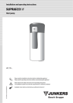
PHILIPS Broadband Fiber Optic System
FOP 0435/011
FOP 0435/011
FOP 0435/011
FOP 0510/011
FOP 0435/011
15V DC
LINE 230V~ 40W
FUSE T 2A H / 250V
Return Path RX
Return Path RX
Return Path RX
Return Path RX
Power Supply
FOP 0330/221 - FOP 0330/321
FOP 0435/021
FOP 0508/011
FOP 0510/011
DIRECTIONS FOR USE
English
02/98 3911 621 74581
SUMMARY
1. GENERAL DESCRIPTION ................................................................................. 2
2. FOP 0330/x21 RETURN PATH TRANSMITTER ............................................... 3
2.1 Overview ...................................................................................................... 3
2.2 Block diagram ....................................................................................... 3
2.3 Mechanical installation .......................................................................... 4
2.3.1 Preliminaries ....................................................................................... 4
2.3.2 Mounting the product ................................................................................. 4
2.3.3 Closing the product .............................................................................. 4
2.3.4 Connectors ......................................................................................... 4
2.4 Electrical / Optical installation ............................................................... 5
2.4.1 Optical fibre connection.............................................................................. 5
2.4.2 Power supply.............................................................................................. 5
2.4.3 Safety......................................................................................................... 6
2.5 Commissioning of transmitter .................................................................... 6
2.6 Characteristics ...................................................................................... 7
2.7 Accessories .......................................................................................... 7
3. FOP 0435/021 RETURN PATH RECEIVER....................................................... 8
3.1 Preliminary inspections.................................................................................8
3.2 Installing the FOP 0508/011 rack................................................................ 8
3.2.1 Connecting the alarm indicators................................................................. 8
3.2.2 Overviews of the (FOP 0508/011 + FOP 0510/011 + FOP 0435/021)........ 9
.
3.3 Installing an FOP 0510/011 power supply........... .....................................10
3.4 Installing an FOP 0435/021 receiver drawer............................................. 10
..
3.5 Commissioning of receiver ....................................................................... 11
Page 1
1. GENERAL DESCRIPTION
The optical return path equipment are used in HFC networks to carry the return signals over optical
fibre from the optical node back to the headend.
It is primarily dedicated to be carriage of return signals for Pay TV, telephony and Internet services,
but may also be used for transporting some video channels.
The system includes two parts :
- The return path transmitter
- The return path receiver
è The FOP 0330/x21 return path transmitter is part of the “Return Path RTR-200” family. It is fully
compatible with the optical return path receiver FOP 0435/021, for point-to-point fibre links.
downstream optical node.
It is compatible with the monitoring system used in the RTR-200
The family is made of 2 versions :
- the FOP 0330/221, mains powered version.
- the FOP 0330/321, powered with 60 Vac CATV line voltage or 48 Vdc telecom voltage.
è The FOP 0435/021 return path receiver is mounted in a 19” FOP 0508/011 rack close
The two assemblies fit into an optical system as described in the diagram below :
Return path block diagram
For a cascade of 2 links
ca
Opti
Hub
l nod
e
RF
end
Head
TX
FOP 0330
RX
RF
RX
TX
RF
RX
RF
TX
FOP 0330
RX
RF
TX
FOP 0330
Fibre
TX : Transmitter
RX : Receiver
Page 2
2. FOP 0330/x21 RETURN PATH TRANSMITTER
2.1 Overview
CLASS 1 LASER EQUIPMENT
INVISIBLE RADIATION LASER
Att Switchable attenuator
P
Variable attenuator
Power
Reference level
2
L
Power green led.
Light on when the optical receiver
is powered.
Test
Filt
Pluggable
low pass filter
Fibre connector
RF test point
S
Earth
D
3
B
Inputs and output description
B - RF main input
D - RF secondary input
S - Power supply input
3 - Output Fibre
2.2 block diagram
S
Att
RF secondary input
D
RF main input
B
Switchable attenuator
Test
15 dB
dB
0-15 dB
Filt
Pluggable
low pass filter
P
Page 3
Variable attenuator
230 V or 60 V
RF test point
3
Output fibre
2.3 Mechanical installation
2.3.1 Preliminaries
Unpack the amplifier and proceed to a visual inspection in case of damages due to transportation. If
any, contact the carrier.
The pack is made of one optical return path transmitter and the Installation and User Manual
It is equipped with an ”all-pass” filter (Filt) (ref : PAS 0226/621).
2.3.2 Mounting the product
220
200
10
171
The amplifier must be installed in well ventilated place and
without any water drop in a shelter or street cabinet.
108.5
Anchor the amplifier vertically, preferably placing connectors
at the bottom, with two ∅ 6 mm screws.
Dimensions : underface view.
2.3.3 Closing the product
a) Check carefully that no water or any moisture is present in the box. If so, remove it.
b) Tighten the four Allen screws (F) on the cover, with a 4-5 N.m torque.
2.3.4 Connectors
S
F
F
T
D
3
B
Connector number
Connector type
Function
Torque load
N.m
B
F
RF main input
9
D
F
RF secondary input
9
3
Wire press
Output fibre
2.5
T
Screw
Earth connection
1.2
F
Screw
Closing the product
4-5
Page 4
2.4 Electrical / Optical
2.4.1 Optical fibre connection
CLASS 1 LASER EQUIPMENT
INVISIBLE RADIATION LASER
Connect the optical fibre according to the next drawing.
Use the anchors to guide the fibre. Carefully position the
fibre avoiding short bends that could break the fibre.
2
Remark :
Before connecting the optical fibre to the transmitter, the
connector should be cleaned carefully :
- Moisten the optical cleaning tip (lint-free) with alcohol.
- Clean the end of the connector.
- Dry it with dry air spray.
CAUTION
Do not look into the optical connector of
the transmitter with power applied.
Invisible LASER light may damage the
eyes.
Important notice
The transmission quality depends strongly on
the optical link quality. Any dirty or defective
optical connector will create optical reflections
that may cause poor intermodulation and
CNR results.
2.4.2 Power supply
a) Mains supply
CAUTION
Never loosen
the wire press
RISK OF ELECTRICAL SHOCK
Caution : to reduce the risk of electrical
shock, do not open under rain
FOP 0330/221
Connect to the local mains
b) Local current injection
FOP 0330/321
Connect to the local power
source according to the drawing.
White / live
Page 5
Blue / neutral
same potential as
the housing (ground)
2.4.3 Safety
Fuse : T 2AL.
The power fuse can be only replaced by a PHILIPS qualified installer.
Any opening attempt of the power part of the machine immediately causes the guarantee
obsolescence.
2.5 Commissioning of transmitter
Example
Procedure
Equipment needed :
Full band QPSK 15 to 65 MHz
- Dual frequency generator (F1 & F2).
- Spectrum analyser
ΠPlug in the low pass filter (Filt) according the
needed return path bandwidth.
• Reference level : 77.6dBµV
• Read the reference level on sticker (L). (see page 3)
Ž Connect a spectrum analyser to the output test point
(Test) of the return path transmitter. (see page 3)
• Connect the frequency generator to the RF main
input (B) or secondary input (D).
Adjust the frequency F1 and F2 and also the
generator output level according to the bandwidth as
indicated in the table below.
• F1= 15 MHz
F2= 65 MHz.
Output level = 60 dBµV for the RF main input or
69 dBµV for the RF secondary input.
• Adjust the test point level, by using the variable
attenuator (P) and the switchable attenuator (Att), to a
value equal to the reference level minus ∆ (see table
below).
• Test point level = Reference level - ∆
= 77.6 dBµV - 14 dB
= 63.6 dBµV
Bandwidth used for QPSK
channels
∆ = Level difference for test point
Output level
(dBµV)
F1
(MHz)
F2
(MHz)
10 to 30 MHz
60
10
30
11.5
15 to 55 MHz
60
15
55
13.5
15 to 65 MHz
60
15
65
14
(dB)
Dual frequency
generator
FOP 0330/221
FOP 0330/321
F1= 15 MHz & F2= 65 MHz
60 dBµV for RF main input
69 dBµV for RF secondary input
Optical
fibre
Test point
for return path transmitter
(63.6 dBµV)
Keep the frequency generator connected to the transmitter in order to adjust the return path receiver
Page 6
2.6. Characteristics
GENERAL
Storage temperature
-40 to +70°C
Operating temperature withing specifications
-15 to +50°C
MECHANICAL
Housing
Rough aluminium
Dimensions (mm) without connectors
220 x 171.5 x 106
Protection according to NFC 20010 or IEC 529
IP 55
Weight
About 2.5 kg
ELECTRICAL
Power supply according to EN 60065
215 - 240V~ / 50 - 60 Hz (FOP 0330/221)
30 à 60 V~ / 30 à 85 V
Consumption
10 W max
Bandwidth
5 - 200 MHz
Input level
Level adjustment
Ripple
video carrier
75 to 95 dBµV
QPSK carrier
57 to 72 dBµV
variable attenuator
0 to -15 dB
switchable attenuator
0 / -15 dB
5 - 65 MHz
< ± 1 dB
5 - 100 MHz
< ± 1.5 dB
5 - 200 MHz
< ± 2 dB
Input impedance
75 Ω
Input adaptation
< -15 dB
(FOP 0330/321)
OPTICAL
Wavelength
1310 ± 30 nm
Output power
1 mW at 25°C
Specifications with a receiver FOP 0435/021
Measurement with 9 dB optical budget, optical connectors included, in the bandwidth 5 - 200 MHz
Signal type
Input level
CNR / 1 MHz
CSO
CTB
Modulation Depth
(dB)
(dB)
(dB)
typical
60
-40
-45
35 %
Two carriers
F1 = 13 MHz
75 - 90 dBµV
F2 = 19 MHz
Nota :
This equipment is certified by the manufacturer to comply with the norms and standards laid down in
the above specifications. When this equipment is purchased, sold and/or installed, check that the
mentioned norms and standard meet the legislation of the country where the product is intended to
be used.
2.7 Accessories
Description
Low pass filter
Range
All pass
5 - 30 MHz
5 - 55 MHz
5 - 65 MHz
Other
Page 7
Product code
PAS 0226/621
PAS 0226/001
PAS 0226/101
PAS 0226/401
On request
3. FOP 0435/021 RETURN PATH RECEIVER
3.1 Preliminary inspections
Installing and setting up the return path receivers require the following equipment :
- flat screwdrivers,
- alcohol and optical tissue,
- stranded wire (telephone pair type),
- dry air spray.
Remove the receiver from its packing and inspect it for possible damage during transport. In the
event of damage, contact the transporter.
The return path FOP 0435/021 fits into a FOP 0508/011 rack.
Each rack can hold up to 8 receiver drawers and 2 FOP 0510/011 power supply drawers.
3.2 Installing the FOP 0508/011 rack
The rack is a 3U height rack that can fit into any standard 19 " bay.
However, it is strongly recommended to use a bracket in order to maintain the completely equipped
rack securely in its bay.
3.2.1 Connecting the alarms (A and B LEDs)
The two LEDs on the front of the FOP 0508/011 (see page 9) must be cabled so that they can light up
when an alarm is detected.
The cabling is on the bottom plate (behind the service plate). See the figure below.
Alarms (A and B) LEDs connection at the bottom plate
Example
+15V
Page 8
3.2.2 Overviews of the (FOP 0508/011 + FOP 0510/011 + FOP 0435/021)
Installation of
0510/011 (power supply)
}
{FOP
FOP 0435/021 (receiver)
in a FOP 0508/011 (19"rack)
Plate locking screws
FOP 0508/011
Service plate
Alarms indicators
15 V on
Power supply 1 defect
ALARM
Power supply2 defect
Receiver alarms
Rack fastening screws
FOP 0435/021
FOP 0510/011
15VDC
LINE 230V~ 40W
Rack fastening screws
Return Path RX
Power Supply
Superior slide
Inferior slide
Page 9
3.3 Installing a FOP 0510/011 power supply
This module supplies 15 Vdc. to the receiver drawers.
- Insert the power supply module carefully along the slide rails into the rack.
- Push the module all the way to the stop plate.
- Using a flat screwdriver, tighten the two screws on the front.
- Plug in a mains cable (2P + T) and connect the module to 230 V mains supply.
From this point on, the module can be turned on using the mains switch.
It is recommended to use two power supplies in parallel, each used at 50% of its capacity for the
advantages of :
- improving the life span of both supplies,
and guaranteeing continuous operation of the rack and drawer assembly in the event of a
breakdown of either supply.
3.4 Installing the FOP 0435/021 receiver drawer
- Insert the receiver carefully along the slide rails into the rack.
- Push the module all the way to the stop plate.
- Using a flat screwdriver, tighten the two screws on the front.
Inhibition of the monitoring system on the receiver
FOP 0435/021
INHIB LED
The optical receiver is prepared to operate with optical transmitters
integrable in return path optical transmitter, type FOP 0330/021 or
FOP 0330/121.
Associated with FOP 0330/221, FOP 0330/321, the monitoring
management must be inhibited. For that change the “OVERRIDE“
switch position to ON.
The “INHIB“ LED blinks, showing that the system is correctly working
without monitoring management.
OVERRIDE switch
Page 10
3.5 Commissioning of receiver
- Connect a spectrum analyser to RF output of the return path receiver ref. FOP 0435/021.
- Adjust the return path receiver by using the attenuator on the optical return path receiver, in order to
have the output level indicated in the table (Example : 75 dBµV for 10 dB optical budget).
Optical Budget
4 dB / 5 km fibre
6 dB / 10 km fibre
10 dB / 20 km fibre
Bandwidth
used for QPSK
channels
CNR
(dB)
Output level
(dBµV)
CNR
(dB)
Output level
(dBµV)
CNR
(dB)
Output level
(dBµV)
10 to 30 MHz
38.5
88.5
40
84.5
42
76.5
15 to 55 MHz
40
86.5
41
82.5
41
74.5
15 to 65 MHz
40
85.5
41
81.5
40
73.5
FOP 0435/021
Dual frequency
generator
Attenuator
FOP 0330/221
FOP 0330/321
Spectrum
analyser
F1= 15 MHz & F2= 65 MHz
60 dBµV for RF main input
69 dBµV for RF secondary input
Optical
fibre
75 dBµV
Test point
for return path transmitter
(63.6 dBµV)
Return Path RX
Value voltage (V)
(Measured to the RF output of the receiver)
11.5 +/- 0.3
6.67 +/- 0.3
4.84 +/- 0.3
2.95 +/- 0.3
1.7 +/- 0.3
Optical Budget (dB) between the transmitter and
the receiver
0
4
6
10
Damaged fibre
Page 11