1
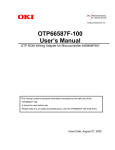
D2
Adding Memory
In this lab, 128k bytes of EPROM and 256k bytes of SRAM will be added to the
SBC. The MC68340 includes chip select and wait state generation logic which
will minimize the glue logic to be supplied by the Altera EPM9320 EPLD. A
simple software algorithm that exercises the EPROM and SRAM will be burned
into the EPROM for test purposes. In a later experiment, a monitor will be installed in the EPROM.
Background
. . . . . . . . . . . . . . . . . . . . . . . . . . . . . . . . . . . . . . . . . . . . . . . . . . . . . . . . . . . . . . . . . . . . . . . . . . . . . . .
"
MC 68340 chip select features
The MC68340 provides up to four integrated chip select lines. A pair of registers
are used to set the base address, range of addresses and access characteristics.
These registers also support internally generated DSACK signals with specified
wait states. Detail information about the location, bit fields and their function
can be found in the MC68340 Integrated Processor User’s Manual, sections
4.2.4, 4.2.5, 4.3.4.1–3. and 4.4.3.
"
Byte lane enables
Memory byte enables are not provided directly from the MC68340. The following table shows the relationship between SIZ and A0 lines that can be used to
provide byte enables. Don’t cares result from MC68340 data alignment requirements.
Transfer Size
Byte
Word
3 byte
Long Word
Size
Address
Word Port Data
SIZ1
SIZ0
A0
D15:D8
0
1
0
Enable
0
1
1
1
0
0
Enable
1
0
1
Don’t care Don’t care
1
1
0
Don’t care Don’t care
1
1
1
Don’t care Don’t care
0
0
0
Enable
0
0
1
Don’t care Don’t care
1
D7:D0
Enable
Enable
Enable
"
Timing
The memory design will be developed using provided memory data sheets and
MC68340 handouts that give timing information. The design must avoid delays
that introduced unneeded wait states. Use the memory control lines and timing
characteristics of the components to provide the maximum timing margins.
Task A
. . . . . . . . . . . . . . . . . . . . . . . . . . . . . . . . . . . . . . . . . . . . . . . . . . . . . . . . . . . . . . . . . . . . . . . . . . . . . . .
"
Design the glue logic for the EPROM and SRAM
Add two 27C512 64k x 8 EPROMs and two KM681000 128K x 8 SRAMs to
your SBC at the locations shown in the memory map on the following page. Refer to Figure 3 in experiment D1 for a pictorial showing physical chip placement.
Also, do the necessary decoding for the VMEbus at this time. Design the glue
logic using MAX+PLUS II with implementation targeting an Altera EPM9320
EPLD. VHDL entry of the EPLD logic is recommended. Refer to Appendix
D2–A for information on code development and the use of the EPP–01CE Hi–Lo
Systems programmer for programming the EPROMs. Develop test code that
will validate the memory interface including the following:
j
j
j
j
j
Valid reads through the SRAM range
Valid writes (byte, word and long) through the SRAM range
Valid reads through the EPROM range
Correct treatment of attempted writes to the EPROM range
Validation of proper address and data line operation.
Task B
. . . . . . . . . . . . . . . . . . . . . . . . . . . . . . . . . . . . . . . . . . . . . . . . . . . . . . . . . . . . . . . . . . . . . . . . . . . . . . .
"
Wire wrap EPROM, SRAM and glue logic sockets to the protoboard
and test
j
j
j
Wire wrap EPROM and SRAM sockets as in experiment D1. Make sure that
the EPLD socket pins are isolated on the PCB. Note some of the wire wrapping of experiment D1 will need to be removed (i.e., pull–up/down on data
lines).
Use the logic analyzer and digital oscilloscope to test your circuit. Be sure
power and ground are not shorted before applying power. Use the single
trace mode to follow the bus cycles of the processor. Verify that the test program is executing.
If test program is not working use the digital oscilloscope to verify interface
signals such as chip select, r/w, etc.
2
$00000000
SRAM
cs1
$0003FFFF
$00040000
Reserved
$0007FFFF
$00080000
EPROM
$0009FFFF
$000A0000
cs0
Reserved
ÇÇÇÇÇÇÇ
ÇÇÇÇÇÇÇ
ÇÇÇÇÇÇÇ
$007FFFFF
$00800000
VME
$009FFFFF
$00A00000
Reserved
$FFFFEFFF
$FFFFF000
$FFFFFFFF
SIM40
Figure 1. SBC Memory Map.
3
cs2
Report
. . . . . . . . . . . . . . . . . . . . . . . . . . . . . . . . . . . . . . . . . . . . . . . . . . . . . . . . . . . . . . . . . . . . . . . . . . . . . . .
"
No formal report. Have available the following
1. VHDL description and wiring diagram of your glue logic.
2. Simulation results.
3. Worst case timing analysis for EPROM and SRAM. Include print–out from the
logic analyzer.
4. Explanation of the test procedure used and results.
4
Appendix D2–A: Assembler & Programming Info
The UNIX–based Avocet 68000 macro cross assembler is available by doing a
swsetup asm68k.
"
Assembly Commands
The assembler source (filename.m68) can be used to create object code records
for downloading to the single board computer using the following commands:
mac68k
a68k
qlink –q
qhex –o3
<filename>
<filename>
<filename>
<filename>
suffix assumed to be .m68
suffix assumed to be .a68
does not require a link file
suffix assumed to be .ltx
qhex will produce a <filename>.hx0 file that can be downloaded from the host.
"
Note: Use qlink –q for initial test program. qlink –s (see below) will be used for
the monitor.
Linking with a .lnk file
If you have a .lnk file use the following command:
qlink –s
"
<filename>
suffix assumed to be .lnk
Splitting ROM files for SBC design
Hex files can be split to accommodate 16–bit systems using two 8–bit ROMs
using the following command:
qhex –d2 –o1
"
<outputfilename0.hex,outputfilename1.hex=inputfilename>
The following steps are required to download files to the PC and using the EPROM programmer.
Steps for downloading file from UNIX account to the PC equipped with programmers in Advanced Microprocessor lab:
j
j
j
j
"
Type ‘ftp leto’ on the PC to start the file transfer protocol session. (You can
also use the Windows based FTP client.)
Enter your login and password.
Change to the appropriate directory and type ‘get <filename>’.
When the transfer has finished, type ‘bye’ to end the ftp session.
Steps for programming using EPP–01CE Quick EPROM Programmer (Hi–Lo Systems)
j
Make sure the programmer is properly connected to the PC. Then, invoke the
Hi–Lo Systems EPROM programmer software using the shortcut to this program in Windows in the MAX+plus II folder called Eprom Programmer.
5
j
j
j
j
j
Select File and then ‘Load the file to buffer’. Use Tab to allow file selection.
Move to the desired HEX file and press enter. When prompted for file type,
select M for Motorola. Accept defaults for the remaining arguments.
There are two different EPROM manufacturers, TI and Microchip. Select
Mfr to set the manufacturer to match you EPROM devices.
Select Type to set the device to 27C512 13V.
Insert the EPROM into the socket, making sure it is as far to the bottom as it
can go.
Select Program to program the device.
Steps to view what has been programmed:
j
j
j
j
select Read
ESC (to main menu)
To see what is on the chip select Display
Remove the EPROM from the programmer socket, making sure to label the
device and cover its window.
Note: The the memory address is based on byte–wide addressing within a single
chip so addresses are divided by 2.
6