1
ec376 TouCAN
Software Package
USER'S MANUAL
1
Introduction
The ec376 from Würz elektronik is the base module for a modular, MC68376-based computer
system providing numerous „real world“ interfaces and 16/32-bit computing power. Using the
MC68376 TOUCAN, up to 200 ec376s may communicate with each other (or with workstations,
PCs or VME CPUs) by means of the object oriented, 1MBit/s Controller Area Network bus
(CAN-Bus).
The ec376 software package, consisting of runtime support, software library and MICROTEC
Research development toolset support significantly reduce the time required for application
software development. To maximize flexibility, application software can be
o
downloaded,
o
debugged and
o
programmed into FLASH memory
on each ec376 unit via CAN or RS-232 without touching the hardware.
The ec376 is based on the HSB-Bus standard, which allows many different CPU (or I/O) add-onmodules from several vendors to coexist on the same bus. The ec376 supports a theoretically
unlimited number of add-on modules, which can interface to the MC68376 parallel bus, the QSPI
(Queued Serial Peripheral Interface), the MC68376 TPU (Time Processor Unit) and parallel port
lines. Additionally, the MC68376 features the TOUCAN, a newly designed CAN controller with
an optically isolated CAN-Bus interface according to the ISO/DIS 11898 standard which is fully
supported by the software package.
2
Hardware Description
The hardware description is intended to give you a brief overview about the ec376 hardware
capabilities and the memory map as defined by the software package. Note that this description
does not describe the hardware in detail. To obtain this information, please refer to the specific
documentation [1][2].
The ec376 module comprises of a MC68376 microcontroller operating at 20.97 MHz clock
frequency, powerup reset logic, up to 1 MByte of static RAM, two JEDEC sockets for EPROMs/
FLASH-EPROMs/PROMs and an RS-232 interface chip. Two onboard intermodule connectors
provide HSB-Bus signals and ultility signals for the connection of add-on modules. Finally, the
ec376 module is equipped with a Berg connector location for the CPU32 „background debug
mode“. For description of the various signals available on this connector, please refer to the
MC68332 manuals [2].
The ec376 uses a maximum of 1 MByte of static RAM and 1 MByte of FLASH-EPROM. All
addresses, wait states and the bus error timeout are software programmable within the MC68376
processors SIM (System Integration Module). For further information please refer to the various
MC68376 manuals [3], which also provide all necessary information to program the QSM
(Queued Serial Module), the PIT (Periodic Interrupt Timer), the TOUCAN, the QUADC
(Queued ADC), the CTM4 (Configurable Timer Module #4) and the TPU (Time Processor Unit).
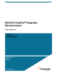
The ec376memory map as programmed by the default firmware is shown in Table 1.
Start-address
End-Address
Access to
$00000000
$000FFFFF
Flash-EPROM(max
$00100000
$001FFFFF
SRAM (max 1 MBytes)
$00FF0000
$00FF07FF
MC68376
$00FFF080
$00FFF180
MC68376
$00FFFA00
$00FFFA7F
MC68376
SIM
$00FFFC00
$00FFFD4F
MC68376
QSPI
Registers
$00FFFE00
$00FFFFF0
MC68376
TPU
Registers
1
internal
MB)
RAM
TouCAN
Registers
Table 1: ec376 memory map
Note also that the address ranges of the FLASH-EPROM and the RAM may vary according to
the actual memory size installed. The actual address ranges with respect to memory size are
shown in Tables 2 and 3. Any access to not implemented locations will result in a bus error
exception.
Start-address
End-Address
Access to
$00000000
$0003FFFF
256
$00000000
$000FFFFF
1
kbyte
MB
Flash-EPROM
Flash_EPROM
Table 2: FLASH-EPROM address with respect to installed memory size
Start-address
End-Address
Access to
$00100000
$0013FFFF
256 kbyte SRAM
$00100000
$001FFFFF
1 MB SRAM
Table 3: SRAM address ranges with respect to installed memory size
The ec376 uses the programmable chip selects of the MC68376 to select the memory-mapped
devices and to provide interrupt acknowledge functions. Table 4 shows the chip select output
assignment. The supported internal and external interrupts are:
•
•
•
•
•
•
Queued Serial Module (QSM)
Periodic Interrupt Timer (PIT)
Time Processor Unit (TPU)
TOUCAN
CTM4
QUADC
The levels and characteristics of these interrupts can be programmed by the corresponding
MC68376 processor registers. Please refer to the various MC683376 manuals [2] for details.
Chip
select
Function
DEVICE
CSBOOT
chip
select
Flash-EPROM
(0 wait states)
CS0-CS2
chip
select
SRAM 70ns Low power
(0 wait states)
CS3-CS4
chip
select
Flash-EPROM (WE for
in-situ
programming)
(90ns)
Table 4: ec376 chip select output assignment
The RS-232 interface allows to connect a terminal or workstation to the ec376 module via a
standard RS-232 port. The resident firmware will set up this port with the following parameters:
•No parity
•8 bits per character
•1 stop bit
•9600 Baud
•Asynchronous protocol
Note that the ec376 RS-232 port does not require any hardware modem control signals (i.e.
DCD/RTS/CTS). All necessary operations will be performed in software. The hardware
connection of the RS-232 interface (with and without RS-232 driver circuit) is described in [1].
3
Software Description
The ec376 software package provides full runtime support for all system resources and the
MICROTEC Research development environment. The runtime support (which is already installed
in the delivered FLASH-EPROMs) consists of:
•
•
Board initialization code;
Debugger Target Kernel/Realtime Kernel with basic I/O routines (RS-232, CAN-Bus) for
debug communication;
o
Resident FLASH-EPROM programming routine.
Additionally, a set of runtime library functions provides access to the onboard devices (i.e.
TOUCAN, QSPI). To support application programming, UNIX shell scripts and Makefiles are
provided as well. The supported ec376devices are:
o
SCI
o
QSPI
o
PIT
o
TOUCAN
The MC68376 TPU is supported by an include file and several demo programs which show how
to use the various functions. The driver function library is fully self-contained and can be used
under any realtime operating systems or standalone. This approach (rather than adapting the
driver functions to each of the different I/O systems) was chosen mainly for two reasons:
1.) When migrating from a bare „C“ environment to a multitasking operating system or from
one operating system to another, the application source code can be adapted more easily.
2.)
Maintaining one function library is less error-prone than maintaining multiple derivates of it.
The idea behind the ec376software concept is quite straightforward: Each time the ec376 module
is powered up, the user application (which has previously been installed in the FLASH memory)
will be booted. If the user user wants to replace the application by another one, he connects a host
computer via RS-232 or CAN-Bus to the ec376 and invokes the source-level debugger suitable
for his develoment environment (i.e. XRAY). Starting this debugger will cause an interrupt to the
ec376, which in turn terminates the user application and activates the resident debugger target
kernel (DTK).
The debugger has now taken control over the ec376 module. The user may download new
software into the SRAM and debug it there until it runs properly. Finally, the new software can be
permanently installed in the ec376 FLASH memory using a resident FLASH programming
routine, which is called from the debugger. After these steps have been completed successfully,
the new application will be booted every time the ec376 module is powered up.
Using CAN for the debugger/DTK link, the debugging protocol is an independant network
service. This means that other, user-programmed protocols may be used at the same time wthout
intervening with the debugging session.
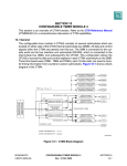
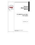
The ec376 resident firmware modifies the exception vector table (EVT) and the MC68376 vector
base register (VBR) to switch between the user application and the DTK. Figure 3-1 shows the
firmware memory layout. For user application support, the EVT is located in FLASH memory
starting from address $0. Initially (after power-up) the VBR points to this EVT, starting the board
initialization routine. This routine initializes the MC68376 SIM/SCI and the TOUCAN controller
so that memory can be accessed and basic I/O works.
On completion, the board initialization routine jumps to the application initialization routine at the
fixed address $8000. The application initialization routine is downloaded and installed together
with the application by the user and performs two actions: It defines the CAN-ID or Internet
address used for the debug communication and copies the user application EVT into RAM and
makes the VBR point to it. Then it jumps to the operating system specific application boot
procedure (i.e. C_ENTRY for MICROTEC C). The application may now modify the EVT entries
to support interrupts or handle specific exceptions. All entries which are not modified will lead to
the DTK initialization procedure. This causes the DTK to be started automatically if an unhandled
exception occurs. Once the DTK is started, it copies the Debugger Target Kernel EVT into RAM
and makes the VBR point to it. This makes sure that a.) the EVT entries can again be modified by
the application and b.) all unhandled exceptions are caught by the DTK and reported to the
debugger.
Developing software for the ec376 is very straightforward. After you have logged into your
workstation, procede as follows:
•
•
•
Make sure that your development environment is properly installed and useable.
Extract the „ec376 SWP“ diskette (tar xvf /dev/fd0c).
Change to the „ec376“ directory. You will find the following subdirectories there:
„bsp“ contains the ec376 firmware in source code. Using the files supplied in this directory, you
are able to modify the firmware (Sections 0,1 and 2 in figure 3-1) and reinstall it on the ec376
module.
„demo“ is an application directory which contains sample applications to play with.
„files“ contains all files which have to be present to build, debug and install a new ec376
application. These files are copied to a new application directory by „mad“.
„inc“ contains the include files which are used by the driver functions library. Depending on
the resources you use in you application, some of these files have to be included in your
sources.
„lib“ contains the driver functions library and all driver functions for ec376 devices in
source code.
„mad“ (contained in the „files“ directory) is a shell script used to make a new application
directory. If you invoke it as „mad app_dir“, it will make sure that the directory „app_dir“ does
not exist, then create it and copy the content of the „files“ directory to it.
o
Create a new application directory with the command „mad test“ and change to this
directory.
o
Start writing your application by creating the devices and installing any required interrupt
service routines using the library function „device_create()“. Consult the sample files in the
„demo“ directory to obtain more information about this procedure.
o
If you are using CAN as debug channel, edit the file „startup.s“ in the working directory and
change the debug Internet address/CAN-ID and the default debug channel definition as desired.
o
Build your application targeted for the debugger by typing „build xray“. This will leave an
object file named „xray.x“ in the working directory. If compilation errors occur, check the
corresponding „xxx.lst“ files.
o
Be sure that your ec376 module is properly connected to your RS-232 port or CAN
(whatever you use as debug channel) and powered up. Then call the host debugger with the
command „dbug xray.x“. After a couple of seconds, the debugger will pop up on your screen.
o
Step through your application and modify it until it runs properly. You may „go“ in endless
loops and break them by typing CTRL-C in the debugger command subwindow.
o
If you want to permanently install your application in the FLASH-EPROMS, type „build
rom“. This will leave an S-record file named „rom.x“ in the working directory.
o
Call the debugger with the command „dbug“.
o
When the debugger is active, type „ldrom“ in the command subwindow. This will download
your application into SRAM.
o
Type „prog“ in the command subwindow. This will program your application into the
FLASH-EPROMs and automatically start it (takes around 10 seconds). After that, quit the
debugger by quitting the X window. Your application will now run each time you power up the
ec376.
o
To create a new application, you may repeat these steps as often as required.
Installing devices is accomplished using the library function „device_create()“. This function
installs the internal devices. For each module it fills a device control block structure to prepare the
system so that all installed system resources can be used through their corresponding driver
functions. Note that this function must be called once before trying to open and use the devices (
preferably right at the beginning of the „main()“ function).
This section covers the driver functions for devices which are available on the ec376.
The CAN-Bus driver supports the MC68376 TOUCAN Controller[3]. The driver functions
provide for the transmission and reception of single CAN messages in a buffered mode. A circular
receive buffer is implemented for each CAN-ID. These buffers are filled by an interrupt service
routine and can be read out in several modes (promiscuous, specific, filtered). The filtered mode
is supported by a configurable CAN-ID acceptance filter. The CAN-Bus driver calls use the
following structured arguments:
1.) „dd“ is the device descriptor which has been obtained using the can_open() call. It is
defined as „short dd“.
2.) „msg_buf“ is a structure that holds a single CAN message, consisting of 0 to 8 data bytes
with additional information about the byte count and the message frame type. It is defined as
follows:
typedef struct
{
char byte_count;
char frame_type;
char msg[8];
} CAN_OBJ;
Using can_read(), you will have to declare a structure of this type and pass it along with the
device descriptor and the CAN-ID. Using can_write(), you must (in addition to that) fill this
structure with the data to be sent before passing it. If you specifiy frame_type as „REMOTE“ in
this case, the byte_count and the message content are ignored.
3.) „arg“ is an argument vector holding 8 parameters used to pass arguments to the can_ctrl()
call. It is defined as „short arg[8]“.
4.) „can_id“ is a variable representing a CAN-ID in the range of 0..MAX_CAN_ID or one of
the specific IDs „ANY_ID“ or „FILTERED“. It is defined as „typedef short CAN_ID“. Be
reminded to always properly cast variables to this type if using them as argument to a can_read(),
can_write() or can_ctrl() call.
5.) „cmd“ is one of the specified commands that can be issued with a can_ctrl() call. It is
defined as „short cmd“.
Synopsis:
#include „necs_lite.h“
#include „can.h“
short can_open(void)
The can_open() call opens the CAN-Bus device for reading or writing and returns a descriptor
for that device. The device must previously have been installed by the device_create() routine to
be considered „existent“. can_open() returns a non-negative device descriptor on success. On
failure, can_open() returns the following error code:
NOEXIST The device has not been installed by device_create().
Synopsis:
#include „necs_lite.h“
#include „can.h“
short can_close(dd)
short dd;
The can_close() call decrements the use count for the CAN-Bus device and assigns it as „not in
use“ in the global device descriptor table if the use count is zero. In that case, it also invalidates
the CAN-ID acceptance filter and sets all CAN-ID receive buffers to circular buffer mode.
Possible return codes of can_close() are:
OK The call could successfully be completed.
INVALID_DESCThe specified device descriptor was not in use, or the device was never installed
by device_create().
Synopsis:
#include „necs_lite.h“
#include „can.h“
short can_read(dd, can_id, msg_buf)
short dd;
CAN_ID can_id;
CAN_OBJ *msg_buf;
The can_read() call attempts to read one complete CAN-Bus message with ID can_id from the
object referenced by the CAN-Bus device descriptor dd into the CAN message buffer pointed to
by msg_buf. The message is read out of a circular receive buffer which holds a maximum of
BUFSIZE CAN messages (Note that the circular buffers can also be switched to an „overwrite“
mode by a can_ctrl() call). With respect to „can_id“, three different read modes are available:
0...MAX_CAN_ID
read.
Normal read mode. The next message for the specified CAN-ID will be
ANY_ID Promiscuous read mode. The next message of the first CAN-ID with pending
messages will be read. The receive buffers are scanned from 0...MAX_CAN_ID. Subsequent
can_read() calls of this type may therefore return high priority messages more often than others.
Note also that the time used by this call may vary, as it depends on how many buffers have to be
scanned before a message is found.
FILTERED
Filtered read mode. The next message of the first CAN-ID acceptance filter
entry with pending messages will be read. The acceptance filter entries are scanned from
0...MAX_CAN_ID. Subsequent can_read() calls of this type may therefore return messages with
low acceptance filter index (= high priority) more often than others. Note also that the time used
by this call may vary, as it depends on how many buffers have to be scanned before a message is
found.
Note that you may mix the different read modes during runtime without restrictions. That means
that CAN-ID acceptance filtering does not prevent you from reading messages for a specific ID
or even all IDs. The normal and promiscuous read modes do not care about the CAN-ID
acceptance filter. All receive buffers are active at any time.
If more than BUFSIZE messages are received by the CAN interrupt service routine without being
read out by can_read() calls , the buffer contents will be overwritten starting with the „oldest“
message. In that case, a corresponding error information is returned. However, if the
corresponding buffer has been switched to „overwrite“ mode, this error information is suppressed,
as it has no meaning in that case. Possible return codes of can_read() are:
OK The call could successfully be completed. The read mode was normal. A CAN message for
the specified CAN-ID has been placed in the buffer.
0..MAX_CAN_ID
The call could successfully be completed. The read mode was
promiscuous or filtered. The return code is the CAN-ID of the message
which has been placed in the buffer.
NOEXIST
The device descriptor dd is not in the range of 0..MAX_DEV_NR.
INVALID_DESC
The device descriptor dd is not a valid descriptor for an opened CANBus device.
CAN_ID_ERR
The specified CAN-ID can_id is not in the range of 0...MAX_CAN_ID,
ANY_ID or FILTERED.
NO_MESSAGE
No message is available for the specified CAN-ID. The circular receive
buffer has been read out completely.
BUF_OVERFLOW
The circular receive buffer has been overrun. One or more CAN messages
have been overwritten and are lost. The message which has been placed in
the buffer, however, is still a valid one. This condition caused the
corresponding circular receive buffer to be flushed automatically.
Synopsis:
#include „necs_lite.h“
#include „can.h“
short can_write(dd, can_id, msg_buf)
short dd;
CAN_ID can_id;
CAN_OBJ *msg_buf;
The can_write() call attempts to write one complete CAN-Bus message with ID can_id to the
object referenced by the CAN-Bus device descriptor dd from the CAN message buffer pointed to
by msg_buf. The message is written into the TOUCAN transmit buffesr which hold 15 CAN
messages. Possible return codes of can_write() are:
OK The call could successfully be completed. The CAN message in msg_buf has been placed in
the circular transmit buffer. Note: this does not mean the message has already been transmitted.
NOEXIST
The device descriptor dd is not in the range of 0..MAX_DEV_NR.
INVALID_DESC
device.
The device descriptor dd is not a valid descriptor for an opened CAN-Bus
CAN_ID_ERR
The specified CAN-ID can_id is not in the range of 0...MAX_CAN_ID.
BYTE_COUNT_ERR
The CAN message byte count which has been specified in msg_buf is out
of the valid range of 0 to 8.
FRAME_TYPE_ERR
The frame type which has been specified in msg_buf is not of type
„DATA“ or „REMOTE“.
CAN_BUS_ERR
The chip transmit buffer did not become available within a defined time
period due to a CAN-Bus problem.
Synopsis:
#include „necs_lite.h“
#include „can.h“
short can_ctrl(dd, request, arg)
short dd;
short request;
short *arg;
The can_ctrl() call performs a special function on the CAN-Bus device referred to by dd. The set
of functions which can be specified by cmd is as follows:
FLUSH_BUFFER
Discard all circular receive buffer contents for the specified CAN-ID (can
be in the range of 0...MAX_CAN_ID, ANY_ID or FILTERED).
INIT_ID_FILTER
Initialize the CAN-ID acceptance filter with the number of entries defined
by arg[0] (the maximum number of entries is MAX_CAN_ID). arg[1] to
arg[...] define the (number of entries) CAN-IDs which shall pass the filter.
The first entry receives highest priority, the second entry second highest
priority and so on.
SET_BUFFER_MODE
Change the receive buffer mode (circular/overwrite) for the
specified CAN-ID. This command requires arg[0] to specify the
CAN-ID for which the call shall be issued (either
0..MAX_CAN_ID, ANY_ID or FILTERED) and arg[1] to be set to
either OVERWRITE or CIRC_BUF. If set to overwrite mode,
can_read() calls to this CAN-ID will always return the last message
which has been received (buffering disabled). You may switch
between these modes during runtime without loosing any data. Note
that the circular buffer mode is the initial mode.
SET_CAN_BAUD
Initialize the CAN-Bus controller chip with user-defined values. This
command requires the following argument:
arg[0]:
TOUCAN baudrate CAN_125K ...
CAN_1M, see „can.h“ for details
Note: This operation performs a complete reset of the chip. A transmission in progress will be
aborted. Take care of the circular receive buffer contents - they are unaffected by this call. Normal
operation will continue immediately after successful completion of the initialization. Are you sure
you do not want to flush the buffers before ?
Possible return codes of can_ctrl() are:
OK
The call could successfully be completed.
NOEXIST The device descriptor dd is not in the range of 0..MAX_DEV_NR.
INVALID_DESC
The device descriptor cd is not a valid descriptor for an opened CAN-Bus device.
INVALID_CMD
The specified command is unknown.
INVALID_ARG
The argument list is incorrect for the specified command.
CAN_ID_ERR
The specified CAN-ID can_id is not in the range of 0...MAX_CAN_ID.
OUT_OF_BUFS
The number of entries specified for the INIT_-ID_FILTER command is bigger than
MAX_CAN_ID.
The PIT driver supports the MC68376 internal Periodic Interrupt Timer (PIT). The driver
functions allow to set up the PIT for periodic interrupts and start/stop it at any time. The actions
taken on each timer tick are defined in tick_isr(). By default, the following global variables are
defined and handled:
int high_time, int low_time
These variables form a 64 bit continous timer which is incremented in timer ticks. „high_time
contains the most significant 32 bits of the time value, while „low_time“ contains the least 32 bits.
int debounce This variable can be set to any value and will be decremented each timer tick until it
reaches zero. Then, no more actions are takenuntil the variable is set to a non-zero value again.
This variable can be used i.e. for mechanical contact debouncing.
These variables may be referenced and used externally without making any changes (just declare
the variable i.e. as „extern int low_time“). However, other actions can be taken by modifying the
tick_isr() function (in the file tick_isr.c).
Synopsis:
#include „necs_lite.h“
#include „tick.h“
short tick_open(void)
The tick_open() call opens the PIT device for configuration and returns a descriptor for that
device. The device must previously have been installed by the device_create() routine to be
considered „existent“. tick_open() returns a non-negative device descriptor on success. On
failure, tick_open() returns the following error code:
NOEXIST The device has not been installed by device_create().
Synopsis:
#include „necs_lite.h“
#include „tick.h“
short tick_close(dd)
short dd;
The tick_close() call decrements the use count for the PIT device and assigns it as „not in use“ in
the global device descriptor table if the use count is zero. In that case, it additionally stops the
timer, so it does not generate any more interrupts. Possible return codes of tick_close() are:
OK The call could successfully be completed.
INVALID_DESC
The specified device descriptor was not in use, or the device was never
installed by device_create().
Synopsis:
#include „necs_lite.h“
#include „tick.h“
short tick_ctrl(dd, request, arg)
short dd;
short request;
short *arg;
The tick_ctrl() call performs a special function on the PIT device referred to by dd. The set of
functions which can be specified by cmd is as follows:
START_TICKS Initialize the PIT device with user-defined tick time. This command requires
arg[0] to be set to a time equivalent between US_125 and SEC_10 (see „tick.h“
for details).
STOP_TICKS Stop the PIT. No more interrupts will be generated, so that the tick_isr() will
not execute any more.
Possible return codes of tick_ctrl() are:
OK
The call could successfully be completed.
NOEXIST
The device descriptor dd is not in the range of 0..MAX_DEV_NR.
INVALID_DESC
The device descriptor cd is not a valid descriptor for the opened PIT device.
INVALID_CMD
The specified command for the tick_ctrl() call was not START_TICKS or
STOP_TICKS.
VEC_UNDEFINED No interrupt vector has been assigned for the PIT device by
device_create().
The QSPI driver supports the MC68376 Queued Serial Peripheral Interface (QSPI). The driver
functions provide for initialization and control of the QSPI and for read/write access to the QSPI
data RAM.
Synopsis:
#include „necs_lite.h“
#include „qspi.h“
short qspi_open(void)
The qspi_open() call opens the QSPI device for reading or writing and returns a descriptor for
that device. The device must previously have been installed by the device_create() routine to be
considered „existent“. qspi_open() returns a non-negative device descriptor on success. On
failure, qspi_open() returns the following error code:
NOEXIST The device has not been installed by device_create().
Synopsis:
#include „necs_lite.h“
#include „qspi.h“
short qspi_close(dd)
short dd;
The qspi_close() call decrements the use count for the QSPI device and assigns it as „not in use“
in the global device descriptor table if the use count is zero. In that case, the QSPI is also
stopped. Possible return codes of qspi_close() are:
OK The call could successfully be completed.
INVALID_DESC
The specified device descriptor was not in use, or the device was never
installed by device_create().
Synopsis:
#include „necs_lite.h“
#include „qspi.h“
short qspi_read(dd, seq_nr, data)
short dd;
short seq_nr;
short *data;
The qspi_read() call reads the QSPI data RAM location specified by seq_nr from the object
referenced by the QSPI device descriptor dd into the buffer pointed to by data. Possible return
codes of qspi_read() are:
OK
The call could successfully be completed. The content of the specified register has
been placed in the buffer.
NOEXIST The device descriptor dd is not in the range of 0..MAX_DEV_NR.
INVALID_DESC
The device descriptor dd is not a valid descriptor for an opened QSPI device.
The seq_nr is not in the range of 0...15.
Synopsis:
#include „necs_lite.h“
#include „qspi.h“
short qspi_write(dd, seq_nr, data)
short dd;
short seq_nr;
short *data;
The qspi_write() call writes the content of the buffer pointed to by data to the QSPI data RAM
location specified by seq_nr of the object referenced by the QSPI device descriptor dd. Possible
return codes of qspi_write() are:
OK
The call could successfully be completed. The specified QSPI data RAM l
ocation has been written.
NOEXIST
The device descriptor dd is not in the range of 0..MAX_DEV_NR.
INVALID_DESC
The device descriptor dd is not a valid descriptor for an opened QSPI device.
INVALID_ARG
The seq_nr is not in the range of 0...15.
Synopsis:
#include „necs_lite.h“
#include „qspi.h“
short qspi_ctrl(dd, request, arg)
short dd;
short request;
short *arg;
The qspi_ctrl() call performs a special function on the QSPI device referred to by dd. The set of
functions which can be specified by cmd is as follows:
INIT_QSPI
Initialize the QSPI with user-defined values. This command requires the
following arguments as initialization values for the QSPI control registers:
arg[0]:
QSPI baudrate SCK_33KHZ ...
SCK_4MHZ,
see „qspi.h“ for details
arg[1]:
Bits per transfer 8 to 15 bits or „0“ for 16 bits
arg[2]:
QSPI mode
WRAPAROUND or SINGLE
Please refer to the MC68376 User’s Manual [3] for further information about the QSPI
initialization.
SET_CMD_RAM
Initialize the QSPI command RAM with user-defined values. This
command requires the following arguments:
arg[0]: Number of command RAM locations to initialize, starting from
location 0
arg[1] to arg [16]: Command RAM initialization values for location 0 to
15. Please refer to the MC68332 USER´s mANUAL for further
information about the QSPI initializion.
START_QSPI Start the QSPI sequencer.
STOP_QSPI Stop the QSPI sequencer in an orderly manner. That is, wait until the transfer in
progress is completed. The QSPI may be restarted from this point using the START_QSPI
command.
STOP_QSPI Stop the QSPI sequencer in an orderly manner. That is, wait until the transfer in
progress is completed. The QSPI may be restarted from this point using the START_QSPI
command.
Possible return codes of qspi_ctrl () are:
OK The call could succesfully be completed.
NOEXIST The device descriptor dd is not in the range of 0..MAX_DEV_NR
INVALID_DESC The device descriptor cd is not a valid descriptor for an opened QSPI device.
INVALID_CMD The specified command is unkown.
INVALID_ARG The argument list is incorrect for the specified command.
SCI (tty) driver The SCI driver supports the MC68332 Serial Communication Interface (SCI)
The driver functions provide for initialization and control of the SCI and for tty data read/write.
Note that while this device is opened, debugging over this channel is not possible.
tty_open() Synopsis:
#include "necs_lite.h"
#include "tty.h"
short tty_open(void)
The tty_open() call opens the SCI device for reading or writing and returns a descriptor for that
device. It also disables the SCI interrupts (which are reenabled by tty_close()). The device must
previously have been installed by the device _create () routine to be considered "
existend".tty_open() returns a non-negative device descriptor on succes. On failure, tty_open()
returns the following error code:
NOEXIST The device has not been installed by device_create()
tty_close()
Synopsis:
#include "necs_lite.h"
#include "tty.h"
short tty_close(dd)
short dd;
The tty_close() call decrements the use count for the SCI device and assigns it as "not in use" in
the global device descriptor table if the use count is zero. In that case, the SCI interrupts are
reenabled. Possible return codes of tty_close() are:
OK The call could succesfully be completed.
INVALID_DESC The specified device descriptor was noz in use, or the device was never
installed by device_create().
tty_read()
Synopsis:
#include "necs_lite.h"
#include "tty.h"
short tty_read(dd)
short dd;
The tty_read() tries to read a character from the object referenced by the SCI device descriptor
dd.tty_read() returns the character on succes. Other possible return codes of tty_read() are:
NOEXIST The device descriptor dd is not in the range of 0..MAX_DEV_NR.
INVALID_DESC The specified device descriptor was not in range of 0..MAX_DEV_NR
NO_MESSAGE No data is available for this device.
tty_write()
Synopsis:
#include "necs_lite.h"
#include "tty.h"
short tty_write(dd)
short dd;
char data;
The tty_write() call writes the content of data to the transmit registers of the object referenced by
the SCI device descriptor dd.tty_write() waits until the transmit buffer becomes available.
Possible return codes of tty_write()
OK The call could successfully be completed. The charakter has been written.
NOEXIST The device descriptor dd is not in the range of 0..MAX_DEV_NR.
INVALID_DESC The specified device descriptor was not in range of 0..MAX_DEV_NR
tty_ctrl()
Synopsis:
#include "necs_lite.h"
#include "tty.h"
short tty_ctrl(dd,request,arg)
short dd;
char request;
short *arg;
The tty_ctrl () call performs a special function on the SCI device refered to by dd. The set of
functions which can be specified by cmd is as follows:
INIT_TTY Initialize the SCI with user-defined values. This command requires the following
arguments as initialization values for the SCI control registers:
arg[0]: SCI baudrate BAUD_110.. BAUD_500k, see tty.h for details
arg[1]: Number of this bits, parity, etc. This is the content of the SCCR1 register.
Refer to the "tty.h" and the MC68332 User,s Manual for details.
Possible return codes of tty_ctrl() are:
OK The call could successfully be completed.
NOEXIST The device descriptor dd is not in the range of 0..MAX_DEV_NR.
INVALID_DEC The device descriptor dd is not a valid descriptor for an opened SCI device.
INVALID_CMD The specified command is unknown.
INVALID_ARG The argument list is incorrect for the specified command.
QADC device driver
qdac_open()
Synopsis:
#include "necs_lite.h"
#include "qadc.h"
short qadc_open(void)
checks if the device exists and returns a descriptor on it.
If found the QADC is initialized for continous conversion of all 16
internally multiplexed channels.return dd on failure qadc_open
returns the following error code
The device descriptor dd is not in the range of 0..MAX_DEV_NR.
NOEXIST
qdac_ctrl()
Synopsis:
#include "necs_lite.h"
#include "qadc.h"
short qadc_czrl
short dd,
short request,
short *arg
The qadc_ctrl ()
call performs a special function on the qadc device refered to by dd. The
set of functions which can be specified by cmd is as follows: INIT_QADC
Initialize the QADC with user-defined values. takes a request and a varia
ble argument vector to perform a special action on the corresponding
device.
OK
NOEXIST
The call could successfully be completed.
The device descriptor dd is not in the range of 0..MAX_DEV_NR.
INVALID_DEC
The device descriptor dd is not a valid descriptor for an opened QADC
device.
The specified command is unknown.
The argument list is incorrect for the specified command.
INVALID_CMD
INVALID_ARG
qdac_read()
Synopsis
#include "necs_lite.h"
#include "qadc.h"
short qadc_read()
short dd
short mode
unsigned short *data
qdac_read()
NOEXIST
returns the converted content of the QADC data RAM.
Right unsigned or left unsigned or left signed
possible error codes are:
The device descriptor dd is not in the range of 0..MAX_DEV_NR.
INVALID_DEC
The device descriptor dd is not a valid descriptor for an opened QADC
device.
qdac_close()
releases the device for further use.
ctm4_close()
Synopsis:
#include „necs_lite.h“
#include „qadc.h“
short qadc_close
short dd;
The qadc_close() call closes the device for further usedevice and
assigns it as „not in use“ in the global device descriptor table if the
use count is zero. In that case, it additionally stops the timer, so it
does not generate any more interrupts. Possible return codes of
qadc_close() are:
OK
The call could successfully be completed.
INVALID_DESC
The specified device descriptor was not in use, or the device was
never installed by device_create().
CTM4 device driver for NECSlite
This file contain the driver functions for the MC68376 configurable timer module (CTM4)
The functions are
* short ctm4_open(void)
* short ctm4_close(short dd)
* short ctm4_ctrl(short dd, short request, short arg)
* short ctm4_write(short dd, short mode, unsigned short data)
*
*
ctm4_open()
Synopsis:
#include "necs_lite.h"
#include "ctm4.h"
short ctm4_open(void)
NOEXIST
checks if the device exists and returns a descriptor on it.
If found the FCSM is initialized to drive TBBA and set up all PWM
channels.
on failure the ctm4_open returns the following error code
The device descriptor dd is not in the range of 0..MAX_DEV_NR.
ctm4_close()
Synopsis:
#include „necs_lite.h“
#include „ctm4.h“
short ctm4_close
short dd;
The ctm4_close() call closes the device for further usedevice and
assigns it as „not in use“ in the global device descriptor table if the
use count is zero. In that case, it additionally stops the timer, so it
does not generate any more interrupts. Possible return codes of
ctm4_close() are:
OK
The call could successfully be completed.
INVALID_DESC
The specified device descriptor was not in use, or the device was
never installed by device_create().
ctm4_ctrl()
Synopsis
#include "necs_lite"
#include "ctm4.h"
short ctm4_ctrl()
short dd,
short request,
short *arg
ctm4_ctrl()
OK
NOEXIST
INVALID_DEC
INVALID_CMD
INVALID_ARG
Initializes the CTM4 with caller-defined parameters takes a request and a
variable argument vector to perform a special action on the correspond in
device. Possible returncodes are:
The call could successfully be completed.
The device descriptor dd is not in the range of 0..MAX_DEV_NR.
The device descriptor dd is not a valid descriptor for an opened CTM4
device.
The specified command is unknown.
The argument list is incorrect for the specified command.
The Ctm4 write() sets the CTM4 PWM outputs
ctm4_write()
Synopsis:
#include „necs_lite.h“
#include „ctm4.h“
short dd
short channel
unsigned short *pulse_width
The ctm4_write call sets the requested PWM channel
possible return codes are :
OK
The call could successfully be completed. The specified Registers has
been written.
NOEXIST
The device descriptor dd is not in the range of 0..MAX_DEV_NR.
INVALID_DESC
The device descriptor dd is not a valid descriptor for an opened ctm4
device.
INVALID_ARG
The the register specified are no ctm4 register