1
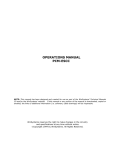
MVME133/D2A2
November 1993
Supplement to
MVME133/MVME133A-20
MPU VMEmodule
User’s Manual
(MVME133/D2)
This supplement provides changes in support of the MVME133S VMEmodule family. The
MVME133 series modules have been replaced by the MVME133S series modules, as follows:
• The MVME133 is replaced by the MVME133S.
•
The MVME133-1 is replaced by the MVME133S-001.
•
The MVME133A is replaced by the MVME133SA-020.
All information in the manual applies to the MVME133S series modules, except that where any
information in the manual applies specifically to a particular module, it now applies to the
equivalent new module as listed above. References to the Z8530 serial communications
controller apply to the Z85C30, which replaces it.
This supplement replaces a previous supplement, MVME133/D2A1. The attached pages are
replacements or additions for the corresponding pages in the manual. Place this page behind the
title page of the manual as a record of this change. Please remove and replace pages according
to the following table:
Replace Old
1-1/1-2
1-7/1-8
2-3/2-4
2-5/2-6
With New
1-1/1-2
1-7/1-8
2-3/2-4
2-5/2-6
•
A vertical bar (|) in the margin of a revised page indicates a text change or addition.
•
The supplement number is shown at the bottom of each revised page.
NOTICE
While reasonable efforts have been made to assure the accuracy of this document, Motorola,
Inc. assumes no liability resulting from any omissions in this document, or from the use of the
information obtained therein. Motorola reserves the right to revise this document and to make
changes from time to time in the content hereof without obligation of Motorola to notify any
person of such revision or changes.
No part of this material may be reproduced or copied in any tangible medium, or stored in a
retrieval system, or transmitted in any form, or by any means, radio, electronic, mechanical,
photocopying, recording or facsimile, or otherwise, without the prior written permission of
Motorola, Inc.
RESTRICTED RIGHTS LEGEND
If the documentation contained herein is supplied, directly or indirectly, to the U.S.
Government, the following notice shall apply unless otherwise agreed to in writing by
Motorola, Inc.
Use, duplication, or disclosure by the Government is subject to restrictions as set forth in
subparagraph (c)(1)(ii) of the Rights in Technical Data and Computer Software clause at
DFARS 252.227-7013.
Motorola, Inc.
Computer Group
2900 South Diablo Way
Tempe, Arizona 85282
CHAPTER 1
GENERAL INFORMATION
Introduction
This manual provides general information, preparation for use and installation instructions,
operating instructions, and functional description for the MVME133S, MVME133S-001, and
MVME133SA-020 MPU VMEmodules.
The module is referred to as the MVME133 throughout this manual except in cases where
individual references are required.
Model Designations
The MVME133 is available in three versions, as listed in Table 1-1.
Table 1-1. Model Designations
Model Number
Description
MVME133S
12.5 MHz MC68020 with 12.5 MHz MC68881
MVME133S-001
16.67 MHz MC68020 with 16.67 MHz MC68881
MVME133SA-020
20 MHz MC68020 with 20 MHz MC68881
Features
The features of the MVME133 include:
• Double-high/single-wide VME board
• Address 24/Data 32 (A24/D32) VMEbus master (A24/D16 compatible)
(MVME133S, MVME133S-001)
• Address 32/Data 32 (A32/D32) VMEbus master (A32/D16, A24/D32, A24/D16
compatible) (MVME133SA-020)
• MC68020 Microprocessor with 32-bit address and data
• 1MB of shared local dynamic RAM, 32 bits wide, accessible from VMEbus
MVME133/D2A2
1-1
GENERAL INFORMATION
• Four 28-pin JEDEC sockets for ROMs/PROMs/EPROMs/EEPROMs (in two banks,
each 16 bits wide) (total 256KB maximum)
• Three 8-bit programmable timers for tick and watchdog functions
• Time-of-day clock/calendar (real-time clock) (MM58274A)
• Front panel asynchronous DB25 serial debug RS-232C port (on MC68901 MFP)
• Dual multiprotocol (synchronous/asynchronous) serial ports (Z85C30):
– RS-485/RS-422A (port A)
– RS-232C (port B)
• VMEbus system controller functions with level 3 arbiter
• Single level bus requester (level is jumper selectable)
• VMEbus interrupter
• VMEbus interrupt handler for all seven levels
• Front panel RUN, HALT, and FAIL status LEDs
• Front panel RESET and ABORT switches
• Remote reset through edge connector P2
• Five-position software-readable header, part of Module Status Register (MSR).
Specifications
The MVME133 specifications are provided in Table 1-1.
Related Documentation
The following publications may provide additional helpful information. If not shipped with this
product, they may be purchased by contacting your local Motorola sales office.
Document Title
Motorola Publication
Number
MVME133S Support Information (refer to the
Support Information section in this chapter)
SIMVME133S/Dx
MVME133 Debugging Package User's Manual
MVME133BUG/Dx
1-2
GENERAL INFORMATION
Document Title
Motorola Publication
Number
MVME133A Debugging Package User’s Manual
MVME133ABUG/Dx
MC68020, MC68EC020 Microprocessors User’s
Manual
M68020UM/AD
MC68881/2 Floating-Point Coprocessor User’s
Manual
MC68881UM/AD
MC68901 Multi-Function Peripheral Data Sheet
MC68901/D
NOTE: Although not shown in the above list, each Motorola Computer Group manual
publication number is suffixed with characters that represent the revision level of the
document, such as /D2 (the second revision of a manual); a supplement bears the same
number as the manual but has a suffix such as /D2A1 (the first supplement to the
manual).
The following publications are available from the sources indicated.
VMEbus Specification information is contained in:
Title:
Versatile Backplane Bus: VMEbus
ANSI/IEEE Std 1014-1987
Source: The Institute of Electrical and Electronics Engineers, Inc.
345 East 47th Street
New York, New York 10017
Z85C30 Serial Communications Controller information is contained in:
Title:
SCC User’s Guide
Source: Zilog, Inc.
210 East Hacienda Avenue
Campbell, CA 95008-6600
MM58274 Real-Time Clock information is contained in:
Title: Data Sheet and Application Note 365
Source: National Semiconductor Corporation
2900 Semiconductor Drive
Santa Clara, CA 95051
Support Information
The MVME133S Intelligent Communications Controller Support Information Manual, part
number SIMVME133S, contains the connector interconnect signal information, parts list, and
MVME133/D2A2
1-7
GENERAL INFORMATION
schematics for the MVME133S/MVME133S-001/MVME133SA-020. Refer to the Related
Documentation table in this chapter for ordering information.
Manual Terminology
Throughout this manual, a convention has been maintained whereby data and address
parameters are preceded by a character which specifies the numeric format as follows:
$
dollar
specifies a hexadecimal number
%
percent
specifies a binary number
&
ampersand
specifies a decimal number
Unless otherwise specified, all address references are in hexadecimal throughout this manual.
An asterisk (*) following the signal name for signals which are level significant denotes that the
signal is true or valid when the signal is low.
An asterisk (*) following the signal name for signals which are edge significant denotes that the
actions initiated by that signal occur on high to low transition.
In this manual, assertion and negation are used to specify forcing a signal to a particular state.
In particular, assertion and assert refer to a signal that is active or true; negation and negate
indicate a signal that is inactive or false. These terms are used independently of the voltage level
(high or low) that they represent.
1-8
MVME133/D2A2
HARDWARE PREPARATION AND INSTALLATION
Table 2-1. Factory Installed Jumper Configuration (cont’d)
Header
Serial port B
configuration select
Jumper
Configuration
Function
J13 1-2, 4-5, 7-8, 10-11, Port B as DCE (to terminal)
13-14, 16-17, 19-20,
22-23, 25-26, 28-29,
31-32
Software-readable
J15 1-2, 3-4, 5-6, 7-8,
header for module status
9-10
register
Module Status Register (MSR)
bits 0 through 4 all =0
Serial ports RTXCx
source select
J16 1-3, 2-4
RTXCA and RTXCB inputs from
onboard 1.23 MHz signal
VMEbus data width
select
J17 1-2
VMEbus is 32-bit data when
[A24] is low, 16-bit data when
[A24] is high
VMEbus addresssize
select
J18 2-3
VMEbus contains both 24-bit and
32-bit address devices; onboard
DRAM responds only to 24-bit
address accesses
Cache disable
E1 and E2 not
connected
(MVME133A-20)
MC68020 on-chip cache memory
not disabled
NOTE: J14 is the front-panel RS-232C connector.
MVME133/D2A1
MVME133/D2A2
2-3
HARDWARE PREPARATION AND INSTALLATION
MVME
FAIL
133S
8
7
J2
2
1
2
1
J3
J4
6
DS3
A1
B1
C1
DS2
1
12
11
J5
1 2
P1
3
1
E1 E2
J18
1
6
5
1
2 J10
J7
6
5
1
2 J9
2
1
2
1
J6
2 J8
S1
A32
B32
C32
S2
J11
1
2
2
1
J4
14
13
PRIMARY SIDE
COMPONENTS REMOVED FOR CLARITY
A1
B1
C1
1
J13
3
31 33
1
J17
25
13
3
P2
J14
1
5
1
9
1
14
SERIAL PORT 1/ CONSOLE
J16
J15
A32
B32
C32
2
6
2
10
1161 9305
MVME133/D2A2
2-4
J1
RUN
1 2
HALT
DS1
ABORT
RESET
TO DTE
Figure 2-1. MVME133 Headers and Connectors
HARDWARE PREPARATION AND INSTALLATION
System Controller Enable Header (J1)
J1
J1
1
2
1
System Controller
(Factory Configuration)
2
Not System Controller
Onboard RAM Offset Select Header (J2)
J2 controls the offset address of the RAM as seen by the VMEbus. The RAM is shared. To the
onboard logic (e.g., a monitor), the RAM address is fixed at $00000000-$000FFFFF. Refer to
the memory map information in Chapter 3 and the shared RAM information in Chapter 4 for
more details.
J2
2
4
J2
6
8
1
3
5
7
OFFSET $00000000
2
4
4
8
2
4
8
2
4
6
8
1
3
5
7
OFFSET $00200000
J2
6
1
3
5
7
OFFSET $00300000
MVME133/D2A1
MVME133/D2A2
6
1
3
5
7
OFFSET $00100000
J2
2
J2
J2
6
8
1
3
5
7
OFFSET $00400000
2
4
6
8
1
3
5
7
OFFSET $00500000
2-5
HARDWARE PREPARATION AND INSTALLATION
J2
2
4
J2
6
8
1
3
5
7
OFFSET $00600000
2
4
J2
6
8
1
3
5
7
OFFSET $00900000
2
4
4
8
1
3
5
7
OFFSET $00700000
2
4
J2
6
8
1
3
5
7
OFFSET $00A00000
J2
2
J2
6
4
8
2
4
8
J2
4
8
2
4
J2
6
8
1
3
5
7
OFFSET $00B00000
J2
6
1
3
5
7
OFFSET $00D00000
2
6
1
3
5
7
OFFSET $00800000
J2
6
1
3
5
7
OFFSET $00C00000
6
8
1
3
5
7
OFFSET $00F00000
2-6
2
2
4
6
8
1
3
5
7
OFFSET $00E00000