1
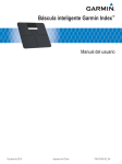
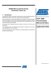
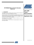
USER GUIDE SAMW25-MR210/510PA Hardware Design Guidelines IEEE 802.11 b/g/n IoT Module Atmel SmartConnect Introduction This document details the hardware design guidelines for a customer to design the Atmel® SAMW25-MR210/510PA module onto their board. Atmel-42436A-SAMW25-MR210510PA-HW-Design-Guide-IEEE802.11bgn-IoT-Module_UserGuide_032015 1 Block Diagram Figure 1-1. Block Diagram of the Module VBAT VCC VDDIO, VDDCORE, VDDANA, VDDIN Printed PCB Antenna VDDIO Chip_En Reset_n Wake SAMD21G18A MCU SPI ATWINC1500 802.11 B/G/N SOC Balun IRQn 26 MHz I2C ATECC508A GPIO_3, 4, 5, 6 2 SAMW25-MR210/510PA Hardware Design Guidelines – IEEE802.11 b/g/n IoT Module [USER GUIDE] 2 Atmel-42436A-SAMW25-MR210510PA-HW-Design-Guide-IEEE802.11bgn-IoT-Module_UserGuide_032015 2 Pinout Information 2.1 Pin Description Figure 2-1. Pin Assignment – Top View SAMW25-MR210/510PA Hardware Design Guidelines – IEEE802.11 b/g/n IoT Module [USER GUIDE] Atmel-42436A-SAMW25-MR210510PA-HW-Design-Guide-IEEE802.11bgn-IoT-Module_UserGuide_032015 3 3 Table 2-1. Pin # 4 Pin Description Pin Description I/O Type Function (default) Programmable Pullup/-down Resistor 1 GND N/A Common Ground 2 UART_TxD ATWINC1500 Output Currently used only for Atmel debug. Not for customer use. Leave unconnected. Yes – Pull-up 3 UART_RxD ATWINC1500 Input Currently used only for Atmel debug. Not for customer use. Leave unconnected. Yes – Pull-up 4 Wi-Fi Chip_En ATWINC1500 Input Currently used only for Atmel debug. Not for customer use. Leave unconnected. No Yes – Pull-up Yes – Pull-up 5 Wi-Fi GPIO_1/RTC ATWINC1500 I/O ATWINC1500 General purpose I/O. Can also be used to input a 32.768kHz Real Time Clock for accurate timing of Wi-Fi sleep intervals. 6 GPIO_3 ATWINC1500 I/O ATWINC1500 General purpose I/O 7 VBAT Power Supply for Wi-Fi RF Power Amplifier and Internal 1.3V Switching Regulator. 8 PA16 Multifunction See SAM D21G Datasheet Yes 9 PA17 Multifunction See SAM D21G Datasheet Yes 10 GND Power Ground 11 PA18 Multifunction See SAM D21G Datasheet Yes 12 PA19 Multifunction See SAM D21G Datasheet Yes 13 PA20 Multifunction See SAM D21G Datasheet Yes 14 PA21 Multifunction See SAM D21G Datasheet Yes 15 PA22 Multifunction See SAM D21G Datasheet Yes 16 PA23 Multifunction See SAM D21G Datasheet Yes 17 GND Power Ground 18 PA24/USB_DM Multifunction Host Interface USB Data Minus pin Yes 19 PA25/USB_DP Multifunction Host Interface USB Data Plus pin Yes 20 GND Power Ground 21 VCC Power Power Supply for I/O 22 PB22 Multifunction See SAM D21G Datasheet Yes 23 PB23 Multifunction See SAM D21G Datasheet Yes 24 RESET_N Input, see SAM D21G Datasheet System Reset. Low level on this pin resets the entire module. Yes SAMW25-MR210/510PA Hardware Design Guidelines – IEEE802.11 b/g/n IoT Module [USER GUIDE] 4 Atmel-42436A-SAMW25-MR210510PA-HW-Design-Guide-IEEE802.11bgn-IoT-Module_UserGuide_032015 Pin # Pin Description I/O Type Function (default) Programmable Pullup/-down Resistor 25 PA30/SWCLK Multifunction Cortex® Serial Wire Debug Interface CLK Yes 26 PA31/SWDIO Multifunction Cortex Serial Wire Debug Interface Data I/O Yes 27 PB02 Multifunction See SAM D21G Datasheet Yes 28 PB03 Multifunction See SAM D21G Datasheet Yes 29 PA00/GPIO/XIN32 Multifunction See SAM D21G Datasheet Yes 30 PA01/GPIO/XOUT32 Multifunction See SAM D21G Datasheet Yes 31 PA02 I/O See SAM D21G Datasheet Yes 32 GND Power Ground Yes 33 PA03 Multifunction See SAM D21G Datasheet Yes 34 PA04 Multifunction See SAM D21G Datasheet Yes 35 PA05 Multifunction See SAM D21G Datasheet Yes 36 PA06 Multifunction See SAM D21G Datasheet Yes 37 PA07 Multifunction See SAM D21G Datasheet Yes 38 PA08 Multifunction See SAM D21G Datasheet Yes 39 PA09 Multifunction See SAM D21G Datasheet Yes 40 PA10 Multifunction See SAM D21G Datasheet Yes 41 PA11 Multifunction See SAM D21G Datasheet Yes 42 GND Power Ground 43 PB10 Multifunction See SAM D21G Datasheet Yes 44 PB11 Multifunction See SAM D21G Datasheet Yes 45 Wi-Fi GPIO_4 ATWINC1500 I/O ATWINC1500 General purpose I/O Yes – Pull-up 46 Wi-Fi GPIO_5 ATWINC1500 I/O ATWINC1500 General purpose I/O Yes – Pull-up 47 Wi-Fi GPIO_6 ATWINC1500 I/O ATWINC1500 General purpose I/O Yes – Pull-up 48 Wi-Fi I2C_SCL ATWINC1500 I/O Currently used only for Atmel debug. Not for customer use. Leave unconnected. Yes – Pull-up 49 Wi-Fi I2C_SDA ATWINC1500 I/O Currently used only for Atmel debug. Not for customer use. Leave unconnected. Yes – Pull-up 50 Wi-Fi Reset_n ATWINC1500 Input Currently used only for Atmel debug. Not for customer use. Leave unconnected. No 51 GND Power Ground SAMW25-MR210/510PA Hardware Design Guidelines – IEEE802.11 b/g/n IoT Module [USER GUIDE] Atmel-42436A-SAMW25-MR210510PA-HW-Design-Guide-IEEE802.11bgn-IoT-Module_UserGuide_032015 5 5 2.2 Module Outline Drawing Figure 2-2. 6 Module Drawings – Top and Bottom Views (unit = mils) SAMW25-MR210/510PA Hardware Design Guidelines – IEEE802.11 b/g/n IoT Module [USER GUIDE] 6 Atmel-42436A-SAMW25-MR210510PA-HW-Design-Guide-IEEE802.11bgn-IoT-Module_UserGuide_032015 3 Reference Schematic 3.1 Schematic Figure 3-1 shows the reference schematic for a system using the SAMW25-MR210/510 module. Figure 3-1. Reference Schematic SAMW25-MR210/510PA Hardware Design Guidelines – IEEE802.11 b/g/n IoT Module [USER GUIDE] Atmel-42436A-SAMW25-MR210510PA-HW-Design-Guide-IEEE802.11bgn-IoT-Module_UserGuide_032015 7 7 4 Notes on Interfacing to the SAMW25 Module 4.1 Programmable Pull-up Resistors The SAMW25-MR210PA provides programmable pull-up resistors on pins 2, 3, 45, 46, 47, 48, and 49. The purpose of these resistors is to keep any unused input pins from floating, which can cause excess current to flow through the input buffer from the VCC supply. Any unused module pin on the SAMW25-MR210PA should leave these pull-up resistors enabled so the pin will not float. The default state at power up is for the pull-up resistor to be enabled. However, any pin used should have the pull-up resistor disabled. The reason for this is that if any pins are driven to a low level while the SAMW25-MR210PA is in the low power sleep state, current will flow from the VCC supply through the pull-up resistors, increasing the current consumption of the module. Since the value of the pull-up resistor is approximately 100kΩ, the current through any pull-up resistor that is being driven low will be VCC/100kΩ. For VCC = 3.3V, the current through each pull-up resistor that is driven low would be approximately 3.3V/100kΩ = 33µA. Pins which are used and have had the programmable pull-up resistor disabled should always be actively driven to either a high or low level and not be allowed to float. See the SAMW25-MR210PA Programming Guide for information on enabling/disabling the programmable pull up resistors. 4.2 Restrictions for Power States When no power is supplied to the device, i.e., the DC/DC Converter output and VCC are both off (at ground potential). In this case, a voltage cannot be applied to the device pins because each pin contains an ESD diode from the pin to supply. This diode will turn ON when voltage higher than one diode-drop is supplied to the pin. If a voltage must be applied to the signal pads while the chip is in a low power state, the VCC supply must be on, so the SLEEP or Power_Down state must be used. Similarly, to prevent the pin-to-ground diode from turning on, do not apply a voltage that is more than one diode-drop below ground to any pin. 4.3 Power-up/-down Sequence The power-up/-down sequence for SAMW25A is shown in Figure 4-1. The timing parameters are provided in Table 4-1. Figure 4-1. Power-up/-down Sequence tR VBATT tA tR t A' VCC Table 4-1. Power-up/-down Sequence Timing Parameter Min. Max. Unit tA 8 0 ms Description VBATT rise to VCC rise Notes VBATT and VCC can rise simultaneously or can be tied together. VCC must not rise before VBATT. SAMW25-MR210/510PA Hardware Design Guidelines – IEEE802.11 b/g/n IoT Module [USER GUIDE] 8 Atmel-42436A-SAMW25-MR210510PA-HW-Design-Guide-IEEE802.11bgn-IoT-Module_UserGuide_032015 Parameter Min. Max. Unit tA’ tR 5 0 ms 0.1 Description VCC fall to VBATT fall Notes VBATT and VCC can fall simultaneously or can be tied together. VBATT must not fall before VCC. V/µs DC supply peripheral I/Os, internal regulator, and analog supply voltage Placement and Routing Guidelines It is critical to follow the recommendations listed below to achieve the best RF performance: When the module is placed on the motherboard, a provision for the antenna must be made. There should be nothing under the portion of the module which contains the antenna. This means the antenna should not be placed directly on top of the motherboard PCB. This can be accomplished by, for example, placing the module at the edge of the board such that the module edge with the antenna extends beyond the main board edge by 6.5mm. Alternatively, a cutout in the motherboard can be provided under the antenna. The cutout should be at least 22 x 6.5mm. Ground vias spaced 2.5mm apart should be placed all around the perimeter of the cutout. No large components should be placed near the antenna. Place a 10µF decoupling capacitor from VBAT to ground right next to pin 7. Place another 10µF capacitor from VCC to ground right next to pin 21. The main board should have a solid ground plane. Each ground pin of the module (including each of the center ground pads) should have a via placed either in the pad or right next to the pad going down to the ground plane. To avoid electromagnetic field blocking, keep large metal objects as far away from antenna as possible Do not enclose the antenna within a metal shield Keep any components which may radiate noise or signals within the 2.4 – 2.5GHz frequency band far away from the antenna or better yet, shield those components. Any noise radiated from the main board in this frequency band will degrade the sensitivity of the module. SAMW25-MR210/510PA Hardware Design Guidelines – IEEE802.11 b/g/n IoT Module [USER GUIDE] Atmel-42436A-SAMW25-MR210510PA-HW-Design-Guide-IEEE802.11bgn-IoT-Module_UserGuide_032015 9 9 6 Antenna Performance Printed PCB antenna on the SAMW25-MR210P is a meandered Inverted F Antenna (IFA). The antenna is fed via matching network which is matched for module installed on 1.5mm thick main board. Main board thickness deviation by ±1mm will change the RX/TX performance by ±1dB maximum referring to the RX/TX performance with default antenna matching network and installed on a 1.5mm thick main board. Measured antenna gain is -6.16dBi. Radiated patterns in three directions for horizontal and vertical polarization are shown below. 10 SAMW25-MR210/510PA Hardware Design Guidelines – IEEE802.11 b/g/n IoT Module [USER GUIDE] 1 Atmel-42436A-SAMW25-MR210510PA-HW-Design-Guide-IEEE802.11bgn-IoT-Module_UserGuide_032015 0 SAMW25-MR210/510PA Hardware Design Guidelines – IEEE802.11 b/g/n IoT Module [USER GUIDE] Atmel-42436A-SAMW25-MR210510PA-HW-Design-Guide-IEEE802.11bgn-IoT-Module_UserGuide_032015 11 1 1 12 SAMW25-MR210/510PA Hardware Design Guidelines – IEEE802.11 b/g/n IoT Module [USER GUIDE] 1 Atmel-42436A-SAMW25-MR210510PA-HW-Design-Guide-IEEE802.11bgn-IoT-Module_UserGuide_032015 2 7 FCC Compliance United States (FCC) This equipment complies with Part 15 of the FCC rules and regulations. To fulfill FCC Certification requirements, an OEM manufacturer must comply with the following regulations: 1. The SAMW25 modular transmitter must be labeled with its own FCC ID number, and, if the FCC ID is not visible when the module is installed inside another device, then the outside of the device into which the module is installed must also display a label referring to the enclosed module. This exterior label can use wording such as the following: Contains Transmitter Module FCC ID: 2ADHKSAMW25 The enclosed device complies with Part 15 of the FCC Rules. Operation is subject to the following two conditions: (i.) this device may not cause harmful interference and (ii.) this device must accept any interference received, including interference that may cause undesired operation. Any similar wording that expresses the same meaning may be used. IMPORTANT: Each module has a label with an FCC ID, however the product User Manual must contain the following statement: “This equipment complies with Part 15 of the FCC Rules. Operation is subject to the following two conditions: (1) this device may not cause harmful interference, and (2) this device must accept any interference received, including interference that may cause undesired operation” (FCC 15.19). The module must be installed into the end product to provide a separation distance of at least 6.5 cm from all persons and must not be co-located or operating in conjunction with any other antenna or transmitter. IMPORTANT: Modifications not expressly approved by this company could void the user's authority to operate this equipment (FCC section 15.21). IMPORTANT: This equipment has been tested and found to comply with the limits for a class B digital device, pursuant to part 15 of the FCC Rules. These limits are designed to provide reasonable protection against harmful interference in a residential installation. This equipment generates, uses and can radiate radio frequency energy and if not installed and used in accordance with the instructions, may cause harmful interference to radio communications. However, there is no guarantee that interference will not occur in a particular installation. If this equipment does cause harmful interference to radio or television reception, which can be determined by turning the equipment off and on, the user is encouraged to try to correct the interference by one or more of the following measures: - Reorient or relocate the module/product. - Increase the separation between the equipment and module/product. - Consult the dealer or an experienced radio/TV technician for help. 8 Interfaces All Communication with the SAMW25 is handled by the internal SAMD21 device. For further information on supported interfaces, timing, drive strengths, etc. refer to the SAMD21 HW design Guide. SAMW25-MR210/510PA Hardware Design Guidelines – IEEE802.11 b/g/n IoT Module [USER GUIDE] Atmel-42436A-SAMW25-MR210510PA-HW-Design-Guide-IEEE802.11bgn-IoT-Module_UserGuide_032015 13 1 3 9 Reference Documentation and Support 9.1 Reference Documents Atmel offers a set of collateral documentation to ease integration and device ramp. The following list of documents available on the Atmel web or integrated into development tools. Table 9-1. Reference Documents Title Content Datasheet Design Files Package User Guide, Schematic, PCB layout, Gerber, BOM and System notes on: RF/Radio Full Test Report, radiation pattern, design guidelines, temperature performance, ESD. Platform Getting started Guide How to use package: Out of the Box starting guide, HW limitations and notes, SW Quick start guidelines HW Design Guide This document SW Design Guide Integration guide with clear description of: High level Arch, overview on how to write a networking application, list all API, parameters and structures. Features of the device, SPI/handshake protocol between device and host MCU, with flow/sequence/state diagram, timing. SW Programmer guide Explain in details the flow chart and how to use each API to implement all generic use cases (e.g. start AP, start STA, provisioning, UDP, TCP, http, TLS, p2p, errors management, connection/transfer recovery mechanism/state diagram) - usage and sample application note For a complete listing of development-support tools and documentation, visit http://www.atmel.com/ or contact the nearest Atmel field representative. 14 SAMW25-MR210/510PA Hardware Design Guidelines – IEEE802.11 b/g/n IoT Module [USER GUIDE] 1 Atmel-42436A-SAMW25-MR210510PA-HW-Design-Guide-IEEE802.11bgn-IoT-Module_UserGuide_032015 4 10 Revision History Doc Rev. Date 42436A 03/2015 Comments Initial document release. SAMW25-MR210/510PA Hardware Design Guidelines – IEEE802.11 b/g/n IoT Module [USER GUIDE] Atmel-42436A-SAMW25-MR210510PA-HW-Design-Guide-IEEE802.11bgn-IoT-Module_UserGuide_032015 15 1 5 Atmel Corporation 1600 Technology Drive, San Jose, CA 95110 USA T: (+1)(408) 441.0311 F: (+1)(408) 436.4200 │ www.atmel.com © 2015 Atmel Corporation. / Rev.: Atmel-42436A-SAMW25-MR210510PA-HW-Design-Guide-IEEE802.11bgn-IoT-Module_UserGuide_032015. Atmel®, Atmel logo and combinations thereof, Enabling Unlimited Possibilities®, and others are registered trademarks or trademarks of Atmel Corporation in U.S. and other countries. ARM®, ARM Connected® logo, and others are the registered trademarks or trademarks of ARM Ltd. Other terms and product names may be trademarks of others. DISCLAIMER: The information in this document is provided in connection with Atmel products. No license, express or implied, by estoppel or other wise, to any intellectual property right is granted by this document or in connection with the sale of Atmel products. EXCEPT AS SE T FORTH IN THE ATMEL TERMS AND CONDITIONS OF SALES LOCATED ON THE ATMEL WEBSITE, ATMEL ASSUMES NO LIABILITY WHATSOEVER AND DISCLAIMS ANY EXPRESS, IMPLIED OR STATUTORY WARRANTY RELATING TO ITS PRODUCTS INCLUDING, BUT NOT LIMITED TO, THE IMPLIED WARRANTY OF MERCHANTABILITY, FITNESS FOR A PARTICULAR PURPOSE, OR NON-INFRINGEMENT. IN NO EVENT SHALL ATMEL BE LIABLE FOR ANY DIRECT, INDIRECT, CONSEQUENTIAL, PUNITIVE, SPECIAL OR INCIDENTAL DAMAGES (INCLUDING, WITHOUT LI MITATION, DAMAGES FOR LOSS AND PROFITS, BUSINESS INTERRUPTION, OR LOSS OF INFORMATION) ARISING OUT OF THE USE OR INABILITY TO USE THIS DOCUMENT, EVEN IF ATMEL HAS BEEN ADVISED OF THE POSSIBILITY OF SUCH DAMAGES. Atmel makes no representations or warranties with respect to the accurac y or completeness of the contents of this document and reserves the right to make changes to specifications and products descriptions at any time without notice. Atmel does not make any commitment to update the information contained herein. Unless specifically provided otherwise, Atmel products are not suitable for, and shall not be used in, automotive applications. Atmel products are not intended , authorized, or warranted for use as components in applications intended to support or sustain life. SAFETY-CRITICAL, MILITARY, AND AUTOMOTIVE APPLICATIONS DISCLAIMER: Atmel products are not designed for and will not be used in connection with any applic ations where the failure of such products would reasonably be expected to result in significant personal injury or death (“Safety -Critical Applications”) without an Atmel officer's specific written consent. Safety-Critical Applications include, without limitation, life support devices and systems, equipment or systems for the operation o f nuclear facilities and weapons systems. Atmel products are not designed nor intended for useHardware in military or aerospace or environments unless specifically desi gnated by[USER Atmel as military-grade. SAMW25-MR210/510PA Design applications Guidelines – IEEE802.11 b/g/n IoT Module GUIDE Atmel products are not designed nor intended for use in automotive applications unless specifica lly designated by Atmel as automotive-grade. Atmel-42436A-SAMW25-MR210510PA-HW-Design-Guide-IEEE802.11bgn-IoT-Module_UserGuide_032015 16 1 6 ]