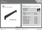
1
CLS Manuals
CLS Manuals
CLS
Par 12
CLSColour
Atmosphere
LED-panel
List of symbols
Protection class
One, two or three
Colour
Available colours;
Amber, blue, red or green
Application area
Indoor or outdoor
6300K
4000K
3000K
RGB
RGB-W
RGB-A
Swivel
Fixture is horizontally rotatable,
indicated in degrees
Curve
Minimal bending curve
in centimeters
Swivel
Fixture is vertically rotatable,
indicated in degrees
Cutting length
Indicated by the
cutting marks
Multiple connection
Daisychain connectivity
LED pitch
Pitch between the
LEDs in millimeters
Installation depth
In centimeters
Mounting hole
In centimeters
Cable length
Maximum cable attached
to the fixture in centimeters
Driver
Inclusive or exclusive
100~240
VAC
100~240
VDC
Max.
20 VA
Max.
3 Watt
IP40
Aluminum
Brushed
Pressure
Maximum pressure on
the fixture in kg/cm2
Luxeon
1x
8º
12 x 50º
Max.
700 mA
Power supply
In VAC, VDC or milliAmpere
Power consumption
In VA or Watt
IP value
Ingress Protection classifies the
degrees of protection provided
against the intrusion of the product
Housing
Housing material
DMX channels
Numbers of DMX channels
on a product
Weight
In grams/kilograms
54º
Colour temperature
White in different Kelvin values;
Cold white, neutral white, warm
white or extra warm white
Colour changing
RGB, RGB-W or RGB-A
Application area
Floor, wall or ceiling
50 cm
2700K
DMX
512
DMX input
Fixture works on DMX512
protocol
Lifespan
Of the light source in hours
Combined product
Compose your own fixture
Lenses
Availble lenses,
indicated in degrees
Warranty
3 years warranty on the product
LEDs
Kind of LED used in the
fixture
Conformité Européenne
CE marking for free marketability of
industrial goods within the EU
Plug & play
Easy connection using the
SmartConnect system
CLS Colour Par 12
Energy label
A
Version 1.0 September 2011
- 12 -
www.cls-led.com
-1-
www.cls-led.com
CLS Colour Par 12
INDEX
Index
2
Introduction
3
Available Colour Par 12
3
Features
3
Included items
3
Optional accessories
3
Safety information
3
Setup and operation modes
4
Control panel menu
4
Control panel menu table
5
DMX-512 control
6
DMX data connection
6
Data terminator
6
DMX start address
6
DMX Channel Assignments
7
Channel values and functions - 6 Channel mode
Technical Specifications
LEDs:
Tricolor RGB
Colour: RGB
Lenses:
25º
Power supply:
Voltage: 100 ~ 240 VAC
Power consumption:
Max. 50 Watt
Primary fuse:
2 amp
Weight:
3,5 kg
Measurements: 258 x 293 x 194 mm (hxwxd)
Control in & output:
XLR 3 pole male-female
Channels:
3, 4, 5 or 6 maximum
Control signal:
DMX 512/1990
Modes:
DMX512 or Stand-Alone
IP value:
IP20
Housing:
Aluminum
Ambient temperature:
Max. 40 ºC
Tricolor
3,5 kg
25º
12 x
RGB
100~240
VAC
Max.
50 Watt
IP20
Aluminum
DMX
512
8
Colour macro/scroll mode
9
Maintenance
10
Troubleshouting
10
Specifications
11
List of symbols
12
2007 CLS-LED BV. All rights reserved. Information subject to change without notice, CLS-LED BV and all affiliated companies disclaim liability for
injury, damage direct or indirect loss, consequential or economic loss or any other loss occasioned by the use of, inability to use or reliance on the
information contained in this manual. No part of this manual may be reproduced, in any form or by any means, without permission in writing from
CLS-LED BV. Other legal information can be found in our General conditions to be found on the back of your CLS-LED BV invoice or on our website
www.cls-led.com/Conditions.pdf
-2-
- 11 -
www.cls-led.com
CLS Colour Par 12
Maintenance
Make sure fixture is cool and disconnected from power mains before any service.
Weekly operating hours and environmental conditions will establish how often the fixtures need cleaning.
Fixtures should be cleaned and inspected at least once a month to maintain optimum performance.
Accumulation of dust and fog residue increases heat build up, can lead to malfunctions, overheating and
reduction in maximum light output, reduced fixture life and over all performance. Before conducting any
maintenance, disconnect fixture from power mains.
• Disconnect fixture from power mains.
• Use a vacuum with a soft brush to remove dust collected on external vents and internal components.
If using an air compressor, use low pressures and extreme care to prevent damaging any internal parts or
effects. 3) Clean all optical elements when the fixture is cold. Use a soft lint free cotton cloth or tissue and
cleaner safe for plastics.
• Inspect clamps and safety cables to ensure fixture is secure and safe.
Troubleshooting
SymptomPossible causes/solutions
No Power
Check for power on mains
Check main fuse and fuse holder
Erratic / No response to DMX
Check data cables: connection and proper wiring
Check Display settings
Check Start Address
Check Master/slave settings
Incorrectly responds to
(Diagnostic technique for DMX issues:
Set suspect fixture’s Start Address the same as a
correctly functioning fixture. If both units then
function correctly, issue is programming)
DMX Check Start Address
Check Start Address
Check for overlapping addresses
Check Menu settings
Check Data cables (faults and proper wiring)
INTRODUCTION
Thank you for selecting the CLS Colour Par 12 with 512 DMX-channels. The CLS Colour Par 12 is a universal
DMX controlled luminairy that uses 12 Tricolor LEDs to create an even light-output.
Available Colour Par 12
• 875590
CLS Colour Par 12, Tricolor-LED DMX 50W 100-240VAC
The CLS Colour Par 12 features:
• 100 ~ 240 VAC input
• Tricolor RGB colour mixing with intensity and strobe effects
• Precise DMX control using 6 channels
• Stand alone or DMX 512 controllable
• Dual joke for floor or mounting
• Indoor use only
Included items
The CLS Colour Par 12 is shipped in one package containing the following items:
• 1 CLS Colour Par 12
• 1 user manual
Optional accessories
• 707028 CLS Zense DMX controller + built in 4 amp RGB dimmer • 707030 CLS ACX60 DMX controller for max. 60 channels • 875580 CLS PAR RGB DMX controller • 911200 CLS Extension cable black XLR male/female 80cm • 911201 CLS Extension cable black XLR male/female 1.5mtr • 911203 CLS Extension cable black XLR male/female 3mtr • 911205 CLS Extension cable black XLR male/female 5mtr • 911206 CLS Extension cable black XLR male/female 10mtr • 911207 CLS Extension cable black XLR male/female 15mtr • 911209 CLS Extension cable black XLR male/female 20mtr
Note: It is important to read this manual before you install this product.
SAFETY INFORMATION
Warning! This product is for professional use only. Read this manual before powering up or
installing the CLS Colour Par 12. Follow the instructions listed below and observe all
warnings in this manual.
- 10 -
-3-
www.cls-led.com
CLS Colour Par 12
Protection from electric shock
• Disconnect the power supply from AC power before installing, dismounting or maintening of the unit.
• Make sure all connectors are connected properly.
• Use only a source of AC power that complies with local building and electrical codes.
• Do not expose the unit to rain or moisture.
• Refer all service to a qualified technician.
Protection from burns and fire
• Provide a clearance of at least 50 mm around the unit.
• Do not install the Colour Par 12 near a heat source.
• Do not install the Colour Par 12 in a corrosive, flammable or explosive area.
• Do not modify the Colour Par 12, or install other than genuine parts.
• Do not operate the unit if the ambient temperature exceeds 35 ºC.
• Operate in a well-ventilated area
Protection from damage due to falls
• Verify that all covers and mounting hardware is securely fastened.
• Block access below the work area whenever installing or removing the unit.
SETUP AND OPERATION MODES (LED SEGMENT DISPLAY)
The following refers to the different modes that are available on this fixture via the LED Segment Control Panel
display. All functions are selectable from the display menu located at the back of the fixture.
Control Panel Menu
Use the fixture’s Control Panel to access the Control Menu. The MENU Key puts the fixture in the settings menu
itself and also acts as a BACK key between options, UP/DOWN moves through the menu options and allows the
assignment of a value.
The ENTER key is used to enter that option and confirms the selection once the UP/DOWN is used to adjust the
value. When in edit, the display will Flash. Settings are stored and recalled on subsequent power cycles. R, G, B,
refers to Red, Green and Blue respectively. DMX and master/slave modes require data cables to be connected
between fixtures. Manual and some stand-alone modes do not require data cables for independent use of the
fixture.
-4-
Colour Macro/Scroll Mode
0-4
5-9
10-14
15-19
20-24
25-29
30-34
35-39
40-44
45-49
50-54
55-59
60-64
65-69
70-74
75-79
80-84
85-89
90-94
95-99
100-104
105-109
110-114
115-119
120-124
125-129
No Macro or Scroll
Cool White
Lt. Blue
Blue
Purple
Blue Magenta
Magenta
Hot Pink
Pink
Red
Orange
Yellow
Lime
Lt. Green
Green
Teal
Cyan
Colour Scroll Snap Speed 1 (Fastest)
Colour Scroll Snap Speed 2
Colour Scroll Snap Speed 3
Colour Scroll Snap Speed 4
Colour Scroll Snap Speed 5
Colour Scroll Snap Speed 6
Colour Scroll Snap Speed 7
Colour Scroll Snap Speed 8
Colour Scroll Snap Speed 9
130-134
135-139
140-144
145-149
150-154
155-159
160-164
165-169
170-174
175-179
180-184
185-189
190-194
195-199
200-204
205-209
210-214
215-219
220-224
225-229
230-234
235-239
240-244
245-249
250-255
Colour Scroll Snap Speed 10
Colour Scroll Snap Speed 11
Colour Scroll Snap Speed 12
Colour Scroll Snap Speed 13
Colour Scroll Snap Speed 14
Colour Scroll Snap Speed 15
Colour Scroll Snap Speed 16
Colour Scroll Snap Speed 17 (Slowest)
Colour Scroll FADE Speed 1 (Fastest)
Colour Scroll FADE Speed 2
Colour Scroll FADE Speed 3
Colour Scroll FADE Speed 4
Colour Scroll FADE Speed 5
Colour Scroll FADE Speed 6
Colour Scroll FADE Speed 7
Colour Scroll FADE Speed 8
Colour Scroll FADE Speed 9
Colour Scroll FADE Speed 10
Colour Scroll FADE Speed 11
Colour Scroll FADE Speed 12
Colour Scroll FADE Speed 13
Colour Scroll FADE Speed 14
Colour Scroll FADE Speed 15
Colour Scroll FADE Speed 16
Colour Scroll FADE Speed 17 (Slowest)
CH 6 : Strobe
The Strobe functions in all modes. The strobe effect will toggle the Master Level between Off and its present
value.
0-4 No Strobe
5-255 Strobe Effect - Slow to Fast
-9-
www.cls-led.com
CLS Colour Par 12
Channel Values and Functions – 6 Channel Mode
CH 1: Master Dimmer
The Master Dimmer controls the actual output level while the relative level of each colour is set by the
R, G or B channels or the Colour Macro/Scroll Channel.
0 – 4 Black Out
5-255 Intensity - Dark to Full Brightness
CH 2: Red
Sets relative intensity of Red. Actual value is subject to Master Dimmer channels. The Colour Macro/Scroll
Channel will override this channel.
0-4 No Output
5-255 Intensity - Off to Full On
CH 3: Green
Sets relative intensity of Green. Actual value is subject to Master Dimmer channels. The Colour Macro/Scroll
Channel will override this channel.
0-4 No Output
5-255 Intensity - Off to Full On
CH 4: Blue
Sets relative intensity of Blue. Actual value is subject to Master Dimmer channels. The Colour Macro/Scroll
Channel will override this channel.
0-4 No Output
5-255 Intensity - Off to Full On
Control Panel Menu Table
The following table describes the control panel’s menu options and settings. What is displayed on the screen is
marked in “quotations”. When this unit powers up, it will display “SYON” for System Power On.
Menu options
Function
Options
MODE
[MODE]
Select Number of DMX operating channels
01 = 3ch, 02 = 4ch, 03 = 5ch or 04 = 6ch
ADDRESS
[ADDR]
Select DMX start address
1-512
COLBALANCE
[COBA]
Enable/disable colour balance preferences
BALANCE [BAL]: Off or on
[RGB]-set individual values for the Colour
balance: R 0-255, G 0-255, B 0-255
DISPLAY
[DISP]
Set the Display Backlight
Off or on
MANUAL
[MANL]
Manual operations options
RESET [RESY]
TEST [TEST]: Test the individual colours:
R 0-255, G 0-255, B 0-255
PROGRAMMER "PROG":
SCENE [SCEN]: 16 user
programmable scenes:
SC01-16 set R 0-255, G 0-255, B 0-255
strobe 0-255
CHASE [CHAS]: 6 user
programmable chases:
CA01-06 set speed S000-255
STANDALONE
[STAL]
functions for automatic run options
SOUND [SOND]: Off or 001 - 100
MASTER [MAST]: Off or on
SLAVE [SLAV]: Off or 001-031
PLAYBACK [PLAY]: Scene SC01-16 or
Chase CA01-06
CH 5: Colour Macro/Scroll
The Colour Macro/Scroll selects between 16 colours and two Colour Scroll Modes. The first Colour Scroll Mode
snaps between colours, the second Colour Scroll Mode fades between colours. This will override the relative
values set by the individual RGB channels 2, 3 & 4.
-8-
-5-
www.cls-led.com
CLS Colour Par 12
DMX-512 CONTROL
Fixtures require a 'Start Address' from 1 to 512, setting the first DMX channel containing data for the fixture
(see DMX Background). Before addressing fixtures, consult the manual of the system’s DMX controller to select
a desirable addressing scheme. Valid Start Addresses range from 1 to 512.
Fixtures requiring more than one channel for control will read subsequent channels up to the total number of
channels required. Since this fixture requires a maximum of 6 channels of DMX, if set to a Start Address of 7
it would use data from channels: 7 and 8, 9, 10, 11, 12. Choose a Start Address so the channels used do not
overlap with other fixtures.
In some cases, it may be desirable to set two or more same type fixtures to the same Start Address. In this
case, the fixtures will be slaved together and respond to the same data. Because all fixtures see the same
data, fixtures may be set to any address without concern for the order they are connected by the DMX cables.
Note: For DMX to operate on this unit, all STAND ALONE options must be set to Off.
DMX Data Connection
This fixture uses 3-pin XLR type connectors and shielded twisted pair cable approved for EIA-422/EIA485 use.
Fixtures are connected in Daisy Chain topography: Connection is made from the controller to the DMX-IN
of the first light, then from the DMX-OUT to the DMX-IN of the next light and so on. Only one data source
can be on a chain and no branching is allowed. The physical order in which the fixtures are connected is not
important, use the most convenient.
Data Terminator
A Data Terminator can be connected to the DMX-OUT of the last fixture to reduce the effects of signal noise;
it is not required for all installations. To make a Terminator, connect a 120-ohm 1/4 watt resistor across pin 2,
Data Negative (S-) and pin 3, Data positive (S+). A qualified technician can determine if a Data Terminator is
needed.
For this example, start with the first unit set to the first possible Start Address = 1. This fixture occupies DMX
channels 1 thru 6. The next DMX channel available for a Start Address is found by adding the previous fixture’s
Start Address to its channel requirement: 1+6=7. To maximize channel usage, we will leave no empty channels
between fixtures so the second Start Address is set to DMX channel 7 and that fixture occupies channels 7
thru 12. The third fixture will be addressed 7+6=13 and occupy channels 13 thru 18. The last fixture is addressed 13+6=19 and will occupy channels 19 thru 24. Thus, 4 fixtures using 6 channels each have Start Addresses
of 1, 7, 13 and 19 and the next free channel in the system is 19+6=25.
DMX Channel Assignments
This fixture features 4 different DMX Channel modes, 3, 4, 5, and 6 channel mode. Using the 6 channel mode
provides the most features, however it takes up the most channels of DMX. The different channel assignments
are shown below. We will provide a full description of the values and functions of the 6 channel mode only. All
other modes of less channels, do the same functions described within the 6 channel mode. Note that the channel order maybe different for each of the mode.
3 channel mode 4 Channel mode
5 Channel mode
6 Channel mode
1 Red (0-255)
1 Red (0-255)
1 Red (0-255)
1 Master dimmer (0-255)
2 Green (0-255)
2 Green (0-255)
2 Green (0-255)
2 Red (0-255)
3 Blue (0-255)
3 Blue (0-255)
3 Blue (0-255)
3 Green (0-255)
4 Master dimmer (0-255)
4 Master dimmer (0-255)
4 Blue (0-255)
5 Strobe (0-255)
5 0-4 No function, 5-84
colour macro, 85-169 colour
snap, 170-255 colour fade
6 Strobe (0-255)
DMX Start Address
To place the fixture in DMX mode, press the MENU key, then using the UP/DOWN keys get to the Address
Menu Option. Press ENTER and using the UP/DOWN buttons, set the start address number for this particular
unit in the DMX chain. Once selected, press ENTER again to save your selection. More than one fixture may
have the same start address, but they will behave the same. Giving a unique start address that does not overlap with any other units allows you to individually control that fixtures’s features fully.
Never allow channels to overlap. You will need to select the number of channels you wish the fixture to use
first. Your choices are 3, 4, 5, or 6 channel modes. This will determine the spacing of channels you will need to
avoid overlapping of channels when selecting your start addresses.
Example: Select Start Addresses for 4 fixtures each requiring 6 channels of DMX (6 channel mode).
-6-
-7-
www.cls-led.com