1
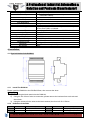
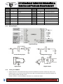
A Professional Industrial Automation & Solution and Products Manufacturer! DAM Series DAM124 4DIN+8AI+4DO Module Model No.:DAM124 WebSite: www.GSM-M2M.com This handbook has been designed as a guide to the installation and operation of King Pigeon Hi-Tech.Co.,Ltd DAM series. Statements contained in the handbook are general guidelines only and in no way are designed to supersede the instructions contained with other products. We recommend that the advice of a registered electrician be sought before any Installation work commences. King Pigeon Hi-Tech.Co., Ltd, its employees and distributors, accept no liability for any loss or damage including consequential damage due to reliance on any material contained in this handbook. King Pigeon Hi-Tech.Co., Ltd, its employees and distributors, accept no liability for GSM Network upgrading or SIMCard upgrading due to the technology specifications contained in this handbook. A Professional Industrial Automation & Solution and Products Manufacturer! 1. Brief instruction The DAM124 is for monitoring 4 digital inputs(can be used as pulse counter), 8 analog inputs, controlling 4 triode drivable digital output(50V/100mA, can be TTL or Pulse output). It supports Modbus RTU Protocol over RS485 serial port. Powered up by 10~30VDC. The DAM124 is used widely in industrial automation control systems. E.g.: Base Transceiver Station, diesel generator rooms, engine room, transformer substations, telecommunication equipment rooms, power supply systems and so on. The DAM124 is an industrial class, high reliability, low-power consumption, high stability and high precision data acquisition module. The DAM124 with fire retardant shell, standard 35mm DIN rail makes it easy to install in fields. Tips: King Pigeon Hi-Tech.Co.,Ltd not only provides competitive prices, excellent quality but also helps customers to solve technical problems, improve quality, reduce extra costs, and assist customers to become more competitive. If our existing modules cannot meet your requirements, we also design and manufacture new models / products according to buyer's request. Any of your requirements is always welcome! 2. Mainly Features 16-bit resolution high precision AD acquisition and data processing techniques; 4 digital input, Dry contact or Wet contact(logic:0~0.5V or NC=0, +3~30V or NO=1, input voltage range: 0~30V, Input Max. voltage range: -10~40V), can be used as pulse counter input: counter sampling frequency:1KHz, impulse width of high or low level must >1mS, Max. counter value is 4 bytes: FFFFFFFFH; 8 analog input, can be 0~20mA,4~20mA,0~5V,0~10V; 4 drivable digital output(triode, not relay inside, 50V/100mA), can be setup as TTL output or Pulse output(impulse width 0.1~20S); Wide range power supply with reverse polarity connection protection; Modbus RTU Protocol; ESD Protection circuit for RS485 serial port; Using industrial-grade chips; Built-in watchdog ensure it reliability; Lightning protection ensure it stability; LEDs for status indication makes it easy to program in filed. 3. Specifications Items Rated Power Input Power Consumption Communication Protocol Modbus Address Data Format Communication Interface Baud Rate King Specifications 10~30VDC(Peak Voltage must≤40V) Typically ≤3W Modbus RTU 1~247 n,8,1; e,8,1; o,8,1 or n,8,2 RS485 1200, 2400, 4800, 9600, 19200, 38400Bps Pigeon Hi-Tech.Co.Ltd. www.GSM-M2M.com 2/6 A Professional Industrial Automation & Solution and Products Manufacturer! Digital Input Drivable Output Analog Input Update Period Measurement Precision Input Resistance Overload Capacity Isolated Type Withstand Tests Installation Type Operation Temperature Storage Temperature Relative Humidity Altitude Temperature Drift Dimension Net Weight 8 digital input, Dry contact or Wet contact 4 drivable digital output(triode, not relay inside,50V/100mA) Default: 4~20mA, optional: 0~20mA, 0~5V, 0~10V 0.25~2S ±0.1%FS Analog channel: Voltage:>1KΩ , current ≤150Ω 1.2 times can sustained,3 times voltage can last 1 second. Digital Input / power / RS485 Serial port / drivable output use the same GND, no isolated. Input /Output /Shell: 2000VAC/min.; 500VDC>100 MΩ 35mm DIN Rail -20~70℃; -40~85℃; 5~95%RH.;(at -40℃, non condensate) 0~3000m ≤100ppm/℃ 118×72×59mm mm(HxWxD) 160g. 4. Installation 4.1 Physical Outlet of the DAM124 4.1.1 Install The DAM124 Please install the DAM124 to the DIN Rail 35mm, then connect the wires. Wiring Tips: 1) Connecting the block terminal to the DAM124; 2) Using the 0.2~3.3mm²wires to connection, please remove the insulator from each wire end about 6mm; 3) Using the screw to fix the wires to the block terminal, the force is 0.56~0.79N·m. 4.1.2 Definition of the PINs PIN Definition PIN Definition 1 V+ Power positive 24 GND Analog Negative (GND) 2 GND Power Negative 23 AI8 8 Analog input positive King Description Pigeon Hi-Tech.Co.Ltd. Description www.GSM-M2M.com th 3/6 A Professional Industrial Automation & Solution and Products Manufacturer! th 3 NC Useless 22 AI7 7 Analog input positive 4 A+ RS485 A+ 21 AI6 6 Analog input positive 5 B- RS485 B- 20 AI5 5 Analog input positive 6 GND Communication GND 19 AI4 4 Analog input positive 7 DI1 1 Digital input positive 18 AI3 3 Analog input positive 8 DI2 2 Digital input positive 17 AI2 2 Analog input positive 9 DI3 3 Digital input positive rd 16 AI1 1 Analog input positive 10 DI4 4 Digital input positive th 15 DO4 4 Digital Output Positive 11 DO1 1 Digital output positive st 14 DO3 3 Digital Output Positive 12 GND Digital Input output GND 13 DO2 2 4.1.3 st nd th th th rd nd st th rd nd Digital Output Positive Wiring Diagram Typically Wiring Current Analog Input Voltage Analog input Digital Input 4.1.4 1. Digital Output Testing the DAM124 Please reference the abovementioned wiring connection to finished the connection. Please only switch on the DAM124 before you’re sure the connections are correct. After connected the power, the RUN LED indicator will flick according to refresh time that you set. Default is Address 1, baud rate 9600bps, data format: n,8,1, refresh time:720ms. King Pigeon Hi-Tech.Co.Ltd. www.GSM-M2M.com 4/6 A Professional Industrial Automation & Solution and Products Manufacturer! The user can change the settings by our configurator. 2. Connect to RS485 network The host should provide the RS485 interface, if no RS485 port, please use the RS232 to RS485 converter. We recommend the user use the isolated RS485 to improve the reliability. In the RS485 network, all of the A+ should connect together, and the B- connect together,too. Also, the GND should connect together then connect to the Communication GND. The RS-485 network usually allow to connect maximum 32 device.if the device more than 32, then please use the RS485 repeater to extend it. The RS-485 network should use the shield twist cable, the shield should connect to GND independently. The RS485 network communication distance maximum is 1200m, when the communication baud rate is high will cause the communication distance short, in this case, please use the RS485 repeater. At the end of the RS485 network, if the communication quality is not good then usually should connect a 120~300Ω/0.25W termination resistors. If the communication quality is good then no need to connect this resistor. 3. Refresh the data The user can setup the analog input refresh time, default is 0.72S, the range is 0.12S~2.4S, the refresh time longer then the reliability of the data is better. Recommend refresh time is 0.6~1.2S. 5.Modbus register tables The register is used for the Modbus RTU protocol. Table 1:Digital output definition, function code 01/05/0F Address Definition Data Description st 0000H DO1 1 digital output:=1 triode close,=0 open. 0001H DO2 2 nd digital output:=1 triode close,=0 open. rd 0002H DO3 3 digital output:=1 triode close,=0 open. 0003H DO4 4 digital output:=1 triode close,=0 open. th Table 2: Digital Input definition, function code 02 Address Definition Data Description st 0000H DI1 1 digital input,=0 short or close,=1 Open or no signal. 0001H DI2 2 nd digital input,=0 short or close,=1 Open or no signal. rd 0003H DI3 3 digital input,=0 short or close,=1 Open or no signal. 0004H DI4 4 digital input,=0 short or close,=1 Open or no signal. th Table 3: Input register, function code 04,RD Address 0000H 0001H 0002H 0003H Definition AI1 AI2 AI3 AI4 Data Description Analog input, no symbol. nd 0~10000 correspond to 0~full range; rd Real valve=DATA/10000*range AI0 th Unit: mA or V. 1 Analog input 2 Analog input 3 Analog input 4 Analog input th 0004H AI5 5 Analog input 0005H AI6 6 Analog input 0006H AI7 7 Analog input 0007H AI8 8 Analog input th th th 0008H… King Remark st Pigeon Hi-Tech.Co.Ltd. Reserved www.GSM-M2M.com 5/6 A Professional Industrial Automation & Solution and Products Manufacturer! 0010H DI DI input status 0011H DO DO output status Low 4 bit is the digital input status: BIT3~0 correspond to DI4~DI1. Low 4 bit is the digital output status: BIT3~0 correspond to DO4~DO1. Table 4: Holding register definition, function code:03/06/10H Address Definition 0000H Mod Device Model 0001H Ver Version 0002H AI0 Analog input range,20 correspond to 20mA. 0003H… Data Description Reserved Abovementioned only can read, below mentioned can read and write. 0008H… Reserved 000BH ADDR Device Address; 1~247;0 is the broadcast address. 000CH COM1 Com setting: high-order 8 bytes reserved. The highest 2 bytes in the low-order bytes is data format: 00 stands for 10bits,equal to n,8,1; 01 stands for 11bits, equal to parity is even e,8,1; 10 stands for 11bits,parity is odd, o,8,1; 11stands for 11 bits, non parity, 2 is stop bit,n,8,2; The low 4 bytes is baud rate: 03~08 stands for 1200~38400BPS; default is 6, equal to 9600bps. 000DH… 0013H Reserved Ts The low 8 bytes is the refresh time: 0.12S~2.4S correspond to 1~20, default is 10 equal to 0.72S, 1 equal to 0.12S. 0014H DO1-PUL DO1 Digital output type,BIT15=1stands for pulse output,=0stands for level output; low 8 bytes is pulse duration time:1~250 correspond to 0.1~25.0S; default is 10. 0015H DO2-PUL DO2 Digital output type, definition is the same as D01. 0016H DO3-PUL DO3 Digital output type, definition is the same as D01. 0017H DO4-PUL DO4 Digital output type, definition is the same as D01. 0018H… Reserved Table 5: Counter Holding register definition, function code: 03/06/10H Address Definition Data Description st 0030H DI1_CntH 1 Digital input 32bit counter high 16 bit. 0031H DI1_CntL 1 Digital input 32bit counter low 16 bit. 0032H DI2_CntH 2 nd Digital input 32bit counter high 16 bit. 2 nd Digital input 32bit counter low 16 bit. 0033H DI2_CntL st rd 0034H DI3_CntH 3 Digital input 32bit counter high 16 bit. 0035H DI3_CntL 3 Digital input 32bit counter low 16 bit. 0036H DI4_CntH 4 Digital input 32bit counter high 16 bit. 0037H DI4_CntL 4 Digital input 32bit counter low 16 bit. rd th th More about Modbus RTU protocol please reference to other documents. The End! Any questions please help to contact us feel free. King Pigeon Hi-Tech.Co.Ltd. www.GSM-M2M.com 6/6