1
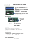
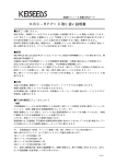
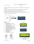
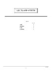
SC1602 16x2 Characters Serial LCD Module Rev 1.2
Introduction
SC1602 is an intelligence LCD module designed to ease project development that
require LCD display. SC1602 is a dot matrix LCD module with serial interface board.
The serial interface board receives and interprets serial data and output the data to
the LCD module accordingly.
With RS232 and TTL inputs, it can be use with any controller with serial port.
(Computers, microcontrollers, microprocessors etc.)
Fig 1: SC1602YG
Two options are available:
Fig 2 – SC1602YG 16x2 Characters, Yellow Green LED Backlight
Fig 2 – SC1602B – 16x2 Characters, White Characters On Blue Backlight
www.siliconcraft.net
-1-
SC1602 16x2 Characters Serial LCD Module Rev 1.2
Features:
• Programmable baud rate 9600bps or 19200bps.
• RS232 or TTL serial interface.
• Simple serial command – clear screen, line feed, clear row, clear column
etc.
• 85 bytes UART receive buffers.
• 11 Screens non volatile memory storage.
• Programmable backlight brightness level.
• Programmable backlight auto off.
• Text scrolling without host intervention.
• Horizontal graph drawing.
• 8 user’s defined characters.
• 2 analog inputs ; 0-10V and 0-20mA
• 3 General Purpose Inputs
• 3 General Purpose Outputs.
• Free application software with custom characters generator.
Hardware Connection
Fig 4 – SC1602 Connectors
Power Supply
5VDC connected through P5 or Pin 1 and Pin 2 of P1.
Warning! Check Power Supply Polarity before turning on the power.
P1 Serial Interface
Warning! Do not Connect RS232 to TTL Pins.
www.siliconcraft.net
Fig 5 – Serial Port Header
-2-
SC1602 16x2 Characters Serial LCD Module Rev 1.2
Fig 6 - RS232 Interface with DB9 Female Connector
Fig 7 - TTL interface with microcontroller
Note: Connection 3 is not required if the inputs and analog ports are not used.
P3 General Purpose I/Os
Inputs MAX 3.3V, 20mA
Outputs 3.3V, 20mA
Fig 8 – P3 Header
www.siliconcraft.net
-3-
SC1602 16x2 Characters Serial LCD Module Rev 1.2
P2 Analog Input Ports
Fig 9 – P2 Header
Communication
All communication is through UART (Universal Asynchronous Receiver Transmitter)
Data format is 8 data bits, no parity and 1 stop bit.
Baud rate is programmable: 9600bps* or 19200bps
* Default value
Sending ASCII characters to the serial LCD will result in text display on the LCD
screen.
Example: Send ASCII text “LCD Demo”
ASCII code in Hexadecimal [0x4C][0x43][0x44][0x20][0x44][0x65][0x6D][0x6F]
The position of the first character depends on the current cursor position.
If the text is more than 16 characters, it will wrap to the next row.
Fig 10 – ASCII character sets
www.siliconcraft.net
-4-
SC1602 16x2 Characters Serial LCD Module Rev 1.2
Control Characters
Backspace
Cursor Home
Next Line
Clear LCD
Cursor Left
Cursor Right
0x08
0x0B
0x0C
0x0D
0x0E
0x0F
Move Cursor one position to the left and delete the character
Send Cursor to row 0, column 0 LCD screen unchanged
Move Cursor to the beginning of next line.
Clear LCD display and Send cursor to row 0, column 0
Move cursor one position to the left
Move cursor one position to the right
User’s Defined Characters
User’s can define up to 8 characters. Each character consists of 8 bytes of data.
Fig 11 – User’s Defined Character Bitmap
To load user’s define characters use command
[0xFE][0x64][64 Bytes of Character Bitmap]
Followed by
[0xFE][0x08]
After which user can display the defined characters by sending
0x00
0x01
0x02
0x03
0x04
0x05
0x06
0x07
for
for
for
for
for
for
for
for
User’s
User’s
User’s
User’s
User’s
User’s
User’s
User’s
Defined
Defined
Defined
Defined
Defined
Defined
Defined
Defined
Character
Character
Character
Character
Character
Character
Character
Character
0
1
2
3
4
5
6
7
Cursor Control
There are two types of cursor : the underline cursor and the block blinking cursor.
Show underline cursor
[0xFE][0x01]
Show block blinking cursor
[0xFE][0x02]
Hide Cursor
www.siliconcraft.net
-5-
SC1602 16x2 Characters Serial LCD Module Rev 1.2
[0xFE][0x03]
Cursor Position Control
Fig 12 – row and column position definition
You can move the cursor to any position by command
[0xFE][0x32][row number][column number]
Delete selected row
[0xFE][0x2D][row]
After this command, cursor points to the beginning of the next line.
Delete selected column
[0xFE][0x2E][column]
After this command, cursor points to the next column
LCD Backlight Control
Turn On
[0xFE][0x06]
Turn Off
[0xFE][0x07]
Backlight will turn off automatically after some time. By default 255 seconds.
You can adjust this interval by command
[0xFE][0x29][interval]
Where interval is max 255 seconds and min 1 second.
Note: Setting the interval to 0 will disabled the auto backlight off feature.
Backlight brightness can be adjusted by command
[0xFE][0x28][brightness level]
Where brightness level is max 250 and min 50
Startup Screen
Start up screen is the screen that the LCD will display every time you power up the
device. It will be displayed for 3s. During this interval the backlight will be turned
on.
www.siliconcraft.net
-6-
SC1602 16x2 Characters Serial LCD Module Rev 1.2
By default, start up screen is not defined and nothing displayed on power up.
User can defined the startup screen by command
[0xFE][0xC8][“row 0 text”][0x0D][“row 1 text”][0xFF]
User’s Defined Screens
User can define up to 10 screens by easy retrieval.
For example, it you need to display
“LINE 1 Custom”
“Screen Demo”
Instead of sending “LINE 1 Custom” [0x0C] “Screen Demo” every time you can
predefine the screen and store it onto the SC1602 memory for easy retrieval.
To define the screen
[0xFF][PAGE][“row 0 text”][0x0D][“row 1 text”][0xFF]
PAGE
PAGE
PAGE
PAGE
PAGE
PAGE
PAGE
PAGE
PAGE
PAGE
=
=
=
=
=
=
=
=
=
=
0xC9
0xCA
0xCB
0xCC
0xCD
0xCE
0xCF
0xD0
0xD1
0xD2
Page
Page
Page
Page
Page
Page
Page
Page
Page
Page
1
2
3
4
5
6
7
8
9
10
To display saved page
Send [0x0D]
to clear the display
Then
Send [0xFE][0x2A][spage] to display the saved screen.
Spage = 0 to 10 where spage 0 is the startup Page
Changing the baud rate
Set baud rate to 9600bps
[0xFE][0x1E]
Set baud rate to 19200bps
[0xFE][0x1F]
LCD will display the baud rate every time you change it. It will be displayed for 1.5s.
Remember Settings
www.siliconcraft.net
-7-
SC1602 16x2 Characters Serial LCD Module Rev 1.2
This command will memorize all settings done on to the non volatile memory and
will be loaded on the next startup.
[0xFE][0x20]
User’s settings include: Backlight Brightness, Auto Off Interval, Baud Rate, Users
defined characters ,start up screen and predefined screens.
Text Scrolling
You can display up to 40 characters per line using the text scrolling mode.
Left to right or right to left scroll is selectable.
Scroll left to right
[0xFE][0xD3][“row 0 text”][0x0D][“row 1 text”][0xFF]
Scroll right to left
[0xFE][0xD4][“row 0 text”][0x0D][“row 1 text”][0xFF]
You must exit the scroll mode by clear LCD command [0x0D] before issuing any
other command.
Horizontal Graph
This command enables you to draw horizontal bar graph on the LCD easily.
Step 1:
Initialize Horizontal Graph Utility
[0xFE][0x04]
Step 2:
Move the cursor to start position
Step 3:
Draw left to right graph
[0xFE][0x2B][length]
Or
Draw right to left graph
[0xFE][0x2C][length]
Fig 13 – Horizontal Bar Graph
Bar graph on Fig 13 is drawn with command
[0xFE][0x04]
[0xFE][0x32][0x00][0x03]
[0xFE][0x2B][0x1B]
Note:
Initialize Bar Graph Utility
Move cursor to row 0,column 3
Draw left to right bar graph of length 27
Maximum length is 80
User’s Defined Characters is unavailable when bar graph is in use.
www.siliconcraft.net
-8-
SC1602 16x2 Characters Serial LCD Module Rev 1.2
Setting The General Purpose Outputs
Command
[0xFE][0x2F][OUTPUT]
OUTPUT
0
1
2
3
4
5
6
7
OUT3
LOW
LOW
LOW
LOW
HIGH
HIGH
HIGH
HIGH
OUT2
LOW
LOW
HIGH
HIGH
LOW
LOW
HIGH
HIGH
OUT1
LOW
HIGH
LOW
HIGH
LOW
HIGH
LOW
HIGH
Table 1 – General Purpose Output
High Logic Level 3.3V
Low Logic Level 0V
Reading General Purpose Inputs Port
3 TTL level inputs available for external connection.
Input Ports is polled every 500ms and its status updated in the internal memory.
This status can be requested by Read Inputs Command [0xFE][0x0A]
SC1602 will response by transmitting the input port status byte ( INPUT )
INPUT INPUT3 INPUT2 INPUT1
0
LOW
LOW
LOW
1
LOW
LOW
HIGH
2
LOW
HIGH
LOW
3
LOW
HIGH
HIGH
4
HIGH
LOW
LOW
5
HIGH
LOW
HIGH
6
HIGH
HIGH
LOW
7
HIGH
HIGH
HIGH
Table 2 – General Purpose Inputs
Analog Input Ports
Two available:
0 to 10VDC and 0-20mA
Both are 10bits resolution
www.siliconcraft.net
-9-
SC1602 16x2 Characters Serial LCD Module Rev 1.2
To read 0-10V port value
[0xFE][0x0B]
Response from SC1602 [0xFA][MSB][LSB]
To read 0-20mA port value
[0xFE][0x0C]
Response from SC1602 [0xFC][MSB][LSB]
Command Summary
FUNCTION
CODE Hexadecimal
CODE
Decimal
Turn on underline cursor
[0xFE][0x01]
[254][1]
Turn on blinking cursor
[0xFE][0x02]
[254][2]
Hide cursor
[0xFE][0x03]
[254][3]
Set cursor position
[0xFE][0x32][row][column]
[254][50][row][column]
Set Backlight brightness level
[0xFE][0x28][level]
[254][40][level]
Turn on backlight
[0xFE][0x06]
[254][6]
Turn off backlight
[0xFE][0x07]
[254][7]
Set auto off interval
[0xFE][0x29][INTERVAL]
[254][41][INTERVAL]
Text Scrolling Mode Setting
[0xFE][smode][LINE1
TEXT] [0x0D][LINE2
TEXT][0xFF]
[0xFE][page][LINE1 TEXT]
[0x0D][LINE2 TEXT][0xFF]
[0xFE][0x2A][spage]
[254][smode][LINE1
TEXT][13][LINE2 TEXT][255]
Save Screen Into Memory
Display Saved Screen
[254][page] [LINE1
TEXT][13][LINE2 TEXT][255]
[254][42][spage]
Initialize Horizontal Graph
Draw
Draw Left to Right Graph
[0xFE][0x04]
[254][4]
[0xFE][0x2B][length]
[254][43][length]
Draw Right to Left Graph
[0xFE][0x2C][length]
[254][44][length]
Defines User’s Characters
[0xFE][0x64][64 bytes Data]
[254][100][64 Bytes Data]
Load User’s Defined Characters
[0xFE][0x08]
[254][8]
Clear row
[0xFE][0x2D][row]
[254][45][row]
Clear column
[0xFE][0x2E][column]
[254][46][column]
Set General Purpose Outputs
[0xFE][0x2F][output]
[254][47][output]
Read General Purpose Inputs
[0xFE][0x0A]
[254][10]
Read 0-10V Analog Port
[0xFE][0x0B]
[254][11]
Read 0-20mA Analog Port
[0xFE][0x0D]
[254][13]
Set baud to 9600bps
[0xFE][0x1E]
[254][30]
Set baud to 19200bps
[0xFE][0x1F]
[254][31]
Remember settings
[0xFE][0x20]
[254][32]
Display Defined Character 0
0x00
0
Display Defined Character 1
0x01
1
www.siliconcraft.net
- 10 -
SC1602 16x2 Characters Serial LCD Module Rev 1.2
Display Defined Character 2
0x02
2
Display Defined Character 3
0x03
3
Display Defined Character 4
0x04
4
Display Defined Character 5
0x05
5
Display Defined Character 6
0x06
6
Display Defined Character 7
0x07
7
Backspace
0x08
8
Send Cursor Home
0x0B
11
Move Cursor to next line
0x0C
12
Clear LCD
0x0D
13
Move Cursor one position left
0x0E
14
Move Cursor one position right
0x0F
15
Electrical Specification
Power Supply:
4.8-5.5V @ 10mA ( Backlight Off )
4.8-5.5V @ 100mA ( Backlight On )
0ºC to 50ºC
-20ºC to 60ºC
Operating Temperature:
Storage Temperature:
Voltage level on TTL inputs:
RXD: 5.5V max
General Purpose Inputs: 3.9V max
Voltage level TTL outputs:
TXD & General Purpose: 3.3V typical 20mA max
0-10V Analog Inputs: 12V max , 0V min
0-20mA Analog Inputs: 50mA max, 0mA min
Mechanical Dimension
Fig 14 – Front view Dimension in mm
www.siliconcraft.net
- 11 -
SC1602 16x2 Characters Serial LCD Module Rev 1.2
Fig 15 – Side view Dimension in mm
SC1602App Software
This application software is available free of charge on
www.siliconcraft.net/download.htm
It is created by Silicon Craft to test and configure SC1602 with computer serial port
connection.
Fig 16 – SC1602App Screenshot
Fig 17 – SC1602App User’s defined characters generator
www.siliconcraft.net
- 12 -